WO2015015648A1 - 充電装置 - Google Patents
充電装置 Download PDFInfo
- Publication number
- WO2015015648A1 WO2015015648A1 PCT/JP2013/071065 JP2013071065W WO2015015648A1 WO 2015015648 A1 WO2015015648 A1 WO 2015015648A1 JP 2013071065 W JP2013071065 W JP 2013071065W WO 2015015648 A1 WO2015015648 A1 WO 2015015648A1
- Authority
- WO
- WIPO (PCT)
- Prior art keywords
- battery
- charging
- power
- terminal
- charging device
- Prior art date
- Legal status (The legal status is an assumption and is not a legal conclusion. Google has not performed a legal analysis and makes no representation as to the accuracy of the status listed.)
- Ceased
Links
Images







Classifications
-
- H—ELECTRICITY
- H02—GENERATION; CONVERSION OR DISTRIBUTION OF ELECTRIC POWER
- H02J—ELECTRIC POWER NETWORKS; CIRCUIT ARRANGEMENTS OR SYSTEMS FOR SUPPLYING OR DISTRIBUTING ELECTRIC POWER; SYSTEMS FOR STORING ELECTRIC ENERGY
- H02J7/00—Circuit arrangements for charging or discharging batteries or for supplying loads from batteries
-
- B—PERFORMING OPERATIONS; TRANSPORTING
- B60—VEHICLES IN GENERAL
- B60L—PROPULSION OF ELECTRICALLY-PROPELLED VEHICLES; SUPPLYING ELECTRIC POWER FOR AUXILIARY EQUIPMENT OF ELECTRICALLY-PROPELLED VEHICLES; ELECTRODYNAMIC BRAKE SYSTEMS FOR VEHICLES IN GENERAL; MAGNETIC SUSPENSION OR LEVITATION FOR VEHICLES; MONITORING OPERATING VARIABLES OF ELECTRICALLY-PROPELLED VEHICLES; ELECTRIC SAFETY DEVICES FOR ELECTRICALLY-PROPELLED VEHICLES
- B60L53/00—Methods of charging batteries, specially adapted for electric vehicles; Charging stations or on-board charging equipment therefor; Exchange of energy storage elements in electric vehicles
-
- H—ELECTRICITY
- H02—GENERATION; CONVERSION OR DISTRIBUTION OF ELECTRIC POWER
- H02J—ELECTRIC POWER NETWORKS; CIRCUIT ARRANGEMENTS OR SYSTEMS FOR SUPPLYING OR DISTRIBUTING ELECTRIC POWER; SYSTEMS FOR STORING ELECTRIC ENERGY
- H02J7/00—Circuit arrangements for charging or discharging batteries or for supplying loads from batteries
- H02J7/02—Circuit arrangements for charging or discharging batteries or for supplying loads from batteries for charging batteries from AC mains by converters
-
- H—ELECTRICITY
- H02—GENERATION; CONVERSION OR DISTRIBUTION OF ELECTRIC POWER
- H02J—ELECTRIC POWER NETWORKS; CIRCUIT ARRANGEMENTS OR SYSTEMS FOR SUPPLYING OR DISTRIBUTING ELECTRIC POWER; SYSTEMS FOR STORING ELECTRIC ENERGY
- H02J7/00—Circuit arrangements for charging or discharging batteries or for supplying loads from batteries
- H02J7/02—Circuit arrangements for charging or discharging batteries or for supplying loads from batteries for charging batteries from AC mains by converters
- H02J7/04—Regulation of charging current or voltage
-
- H—ELECTRICITY
- H02—GENERATION; CONVERSION OR DISTRIBUTION OF ELECTRIC POWER
- H02J—ELECTRIC POWER NETWORKS; CIRCUIT ARRANGEMENTS OR SYSTEMS FOR SUPPLYING OR DISTRIBUTING ELECTRIC POWER; SYSTEMS FOR STORING ELECTRIC ENERGY
- H02J2105/00—Networks for supplying or distributing electric power characterised by their spatial reach or by the load
- H02J2105/30—Networks for supplying or distributing electric power characterised by their spatial reach or by the load the load networks being external to vehicles, i.e. exchanging power with vehicles
- H02J2105/33—Networks for supplying or distributing electric power characterised by their spatial reach or by the load the load networks being external to vehicles, i.e. exchanging power with vehicles exchanging power with road vehicles
- H02J2105/37—Networks for supplying or distributing electric power characterised by their spatial reach or by the load the load networks being external to vehicles, i.e. exchanging power with vehicles exchanging power with road vehicles exchanging power with electric vehicles [EV] or with hybrid electric vehicles [HEV]
-
- Y—GENERAL TAGGING OF NEW TECHNOLOGICAL DEVELOPMENTS; GENERAL TAGGING OF CROSS-SECTIONAL TECHNOLOGIES SPANNING OVER SEVERAL SECTIONS OF THE IPC; TECHNICAL SUBJECTS COVERED BY FORMER USPC CROSS-REFERENCE ART COLLECTIONS [XRACs] AND DIGESTS
- Y02—TECHNOLOGIES OR APPLICATIONS FOR MITIGATION OR ADAPTATION AGAINST CLIMATE CHANGE
- Y02T—CLIMATE CHANGE MITIGATION TECHNOLOGIES RELATED TO TRANSPORTATION
- Y02T10/00—Road transport of goods or passengers
- Y02T10/60—Other road transportation technologies with climate change mitigation effect
- Y02T10/70—Energy storage systems for electromobility, e.g. batteries
-
- Y—GENERAL TAGGING OF NEW TECHNOLOGICAL DEVELOPMENTS; GENERAL TAGGING OF CROSS-SECTIONAL TECHNOLOGIES SPANNING OVER SEVERAL SECTIONS OF THE IPC; TECHNICAL SUBJECTS COVERED BY FORMER USPC CROSS-REFERENCE ART COLLECTIONS [XRACs] AND DIGESTS
- Y02—TECHNOLOGIES OR APPLICATIONS FOR MITIGATION OR ADAPTATION AGAINST CLIMATE CHANGE
- Y02T—CLIMATE CHANGE MITIGATION TECHNOLOGIES RELATED TO TRANSPORTATION
- Y02T10/00—Road transport of goods or passengers
- Y02T10/60—Other road transportation technologies with climate change mitigation effect
- Y02T10/7072—Electromobility specific charging systems or methods for batteries, ultracapacitors, supercapacitors or double-layer capacitors
-
- Y—GENERAL TAGGING OF NEW TECHNOLOGICAL DEVELOPMENTS; GENERAL TAGGING OF CROSS-SECTIONAL TECHNOLOGIES SPANNING OVER SEVERAL SECTIONS OF THE IPC; TECHNICAL SUBJECTS COVERED BY FORMER USPC CROSS-REFERENCE ART COLLECTIONS [XRACs] AND DIGESTS
- Y02—TECHNOLOGIES OR APPLICATIONS FOR MITIGATION OR ADAPTATION AGAINST CLIMATE CHANGE
- Y02T—CLIMATE CHANGE MITIGATION TECHNOLOGIES RELATED TO TRANSPORTATION
- Y02T90/00—Enabling technologies or technologies with a potential or indirect contribution to GHG emissions mitigation
- Y02T90/10—Technologies relating to charging of electric vehicles
- Y02T90/14—Plug-in electric vehicles
-
- Y—GENERAL TAGGING OF NEW TECHNOLOGICAL DEVELOPMENTS; GENERAL TAGGING OF CROSS-SECTIONAL TECHNOLOGIES SPANNING OVER SEVERAL SECTIONS OF THE IPC; TECHNICAL SUBJECTS COVERED BY FORMER USPC CROSS-REFERENCE ART COLLECTIONS [XRACs] AND DIGESTS
- Y02—TECHNOLOGIES OR APPLICATIONS FOR MITIGATION OR ADAPTATION AGAINST CLIMATE CHANGE
- Y02T—CLIMATE CHANGE MITIGATION TECHNOLOGIES RELATED TO TRANSPORTATION
- Y02T90/00—Enabling technologies or technologies with a potential or indirect contribution to GHG emissions mitigation
- Y02T90/10—Technologies relating to charging of electric vehicles
- Y02T90/16—Information or communication technologies improving the operation of electric vehicles
Definitions
- the present invention relates to a charging device mounted with a battery, for example, for charging a battery of a battery-type work vehicle driven by an electric motor driven by power supplied from the battery.
- Patent Document 1 describes a charging system that manages charging of a worker's battery at a base station provided with a charging device.
- the charging device may be enlarged.
- An object of the present invention is to perform battery management while suppressing an increase in size of a battery-type work vehicle.
- the present invention is a device comprising a battery and at least one electric motor, wherein the electric motor is a device for charging the battery of a work vehicle driven by electric power supplied from the battery, which converts AC power into DC power.
- a conversion unit a control unit that controls charging of the battery based on an instruction from an on-board control device mounted on the work vehicle, a terminal for power supply that supplies the DC power to the battery, the work vehicle,
- a charging device comprising: a communication terminal for communication; and a start terminal for transmitting a signal for activating the on-vehicle control device.
- the terminal for power supply, the terminal for communication, and the terminal for activation be arranged in the same connector.
- the present invention can perform battery management while suppressing an increase in size of a battery-type work vehicle.
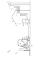
- FIG. 1 is a diagram showing a work vehicle charging system according to the present embodiment.
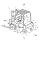
- FIG. 2 is a side view showing the battery type forklift according to the present embodiment as viewed from the left side.
- FIG. 3 is a perspective view showing the battery-powered forklift according to the present embodiment as viewed from the upper left rear left side.
- FIG. 4 is a block diagram for explaining an electric system of the battery type forklift according to the present embodiment.
- FIG. 5 is an explanatory view of a battery provided in the battery-type forklift according to the present embodiment.
- FIG. 6 is a view showing a charging device side connector and a charging connector.
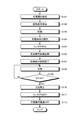
- FIG. 7 is a flowchart showing an example of the operation of the on-vehicle control device, the charging device, etc. when charging the battery.
- FIG. 8 is a perspective view showing a battery and a battery case according to the present embodiment.
- FIG. 9 is a plan view showing a battery and a battery case according to the present embodiment.
- FIG. 10 is a right side view showing the battery and the battery case according to the present embodiment.
- FIG. 11 is a left side view showing the battery and the battery case according to the present embodiment.
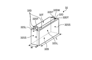
- FIG. 12 is a perspective view showing an example of a battery cell provided in the battery according to the present embodiment.
- FIG. 13 is a view on arrow AA of FIG.
- FIG. 14 is a view showing the relationship between the battery case and the bar.
- FIG. 15 is a plan view showing a state in which the upper part of the battery case is removed.
- FIG. 16 is a view showing the structure of the storage case.
- FIG. 1 is a diagram showing a work vehicle charging system according to the present embodiment.
- a battery type forklift 1 is explained as an example as a work vehicle, a work vehicle is not limited to this.
- the work vehicle may be a wheel loader or hydraulic excavator driven by power from a battery or power obtained from a generator driven by an engine or the like.
- the work vehicle charging system 100 includes a battery-type forklift 1 and a charging device 2.
- the battery-type forklift 1 is a battery-type work vehicle including a battery 30 as a work vehicle battery and at least one electric motor driven by the power supplied from the battery 30.
- the at least one electric motor is, for example, an electric motor for causing the battery-powered forklift 1 to travel.
- the charging device 2 is a stationary device installed in the building HT or under the eaves of the building HT.
- the charging device 2 is supplied with three-phase alternating current from the switchboard 3 in the building HT.
- the charging device 2 can rapidly charge the battery 30 of the battery type forklift 1.
- the switchboard 3 is supplied with AC power from the pole transformer 4, for example.
- the pole transformer 4 is supplied with AC power from the substation via the power line 5.
- the charging device side connector 24 of the charging device 2 is connected to the charging connector 23 at rest time or the like, and the battery 30 is charged. When using the rest time, the battery 30 is rapidly charged.
- FIG. 2 is a side view showing the battery type forklift according to the present embodiment as viewed from the left side.
- FIG. 3 is a perspective view showing the battery-powered forklift according to the present embodiment as viewed from the upper left rear left side.
- the side on which the fork 13 is provided is the front side
- the side on which the counterweight 20 is provided is the rear side.
- the side directed from the driver's seat 34 to the handle 36 serving as the operating device is the front
- the side directed from the handle 36 to the driver's seat 34 is the rear.
- an operating lever for operating a working machine is also included in a hydraulic shovel, a wheel loader, and the like.
- right and left mean right and left with respect to the front.
- the left-right direction is the width direction of the vehicle body 10 as the main body of the work vehicle.
- the upper side is orthogonal to a plane (grounding plane) in contact with at least three of the front wheel 11 and the rear wheel 12 and is a side facing the central axis of rotation of the front wheel 11 or the rear wheel 12 from the ground plane.
- the lower side is the side from the rotation center axis of the front wheel 11 or the rear wheel 12 toward the ground contact plane.
- a longitudinal axis An axis extending in the longitudinal direction of the vehicle body 10 and passing through the center in the width direction of the vehicle body 10 is referred to as a longitudinal axis, and an axis orthogonal to the longitudinal axis and parallel to the installation plane and heading in the lateral direction of the vehicle body 10 is referred to as a lateral axis.
- the vertical axis of the vehicle body 10 is referred to as the vertical axis.
- the vertical axis is orthogonal to both the longitudinal axis and the horizontal axis.
- the plan view refers to the state viewed from above.
- the battery-type forklift 1 includes front wheels 11 at front corners of the vehicle body 10 and rear wheels 12 at rear corners of the vehicle body 10.
- the battery type forklift 1 travels by driving the front wheel 11 by a traveling electric motor (traveling motor) 50 provided behind the front wheel 11. More specifically, the output of the traction motor 50 is transmitted to both front wheels 11 and 11 via a power transmission device 51 having a speed reducing function to drive them.
- traveling motor traveling motor
- a PM (Permanent Magnet) type that is, a type in which the rotor has a permanent magnet can be used as the traveling motor 50.
- the PM type motor When the PM type motor is used as the traveling motor 50, it may be an SPM (Surface Permanent Magnet) type or an IPM (Interior Permanent Magnet) type.
- a fork 13 is provided for loading and unloading or moving a load.
- the fork 13 is supported by a mast 14 provided along the vertical direction.
- the fork 13 is raised and lowered along the mast 14 by the drive of a mast cylinder 15 provided between the fork 13 and the mast 14.
- the mast 14 is attached to the vehicle body 10 so as to be rotatable about the left and right axes at its lower end.
- the mast 14 is provided with a tilt cylinder (not shown) with the vehicle body 10.
- the mast 14 can be inclined forward or backward with respect to the vehicle body 10 by driving the tilt cylinder.
- a counterweight 20 is provided at the rear end of the vehicle body 10.
- the counterweight 20 is a weight for balancing when the fork 13 supports a load.
- the counterweight 20 is made of, for example, metal, but is not limited thereto.
- the counterweight 20 is disposed in a portion of the vehicle body 10 from the portion above the rear wheel 12 to the rear end.
- the battery type forklift 1 includes an accelerator pedal 37, a brake pedal 38, and a traveling direction switching lever 39.
- the accelerator pedal 37 is a member for operation which controls the output and rotation direction of the travel motor 50.
- the brake pedal 38 is an operation member for stopping the battery type forklift 1.
- the advancing direction switching lever 39 is a member for operation for switching the advancing direction of the battery type forklift 1 to either the front or the rear.
- the battery-type forklift 1 includes a charging connector 23. When charging the battery 30, the charging connector 23 of the charging device 2 shown in FIG. 1 is connected to the charging connector 23. When the charging device side connector 24 is not connected, the charging connector 23 is attached with a lid for waterproofing.
- the battery type forklift 1 includes a display panel 52 as a display device in front of the handle 36.
- the display panel 52 has an input unit for performing various settings on the battery type forklift 1 and a display unit for displaying information on the state of the battery type forklift 1 and the like.
- the operator of the battery-type forklift 1 makes various settings for the battery-type forklift 1 through the display panel 52.
- the information on the state or the like of the battery type forklift 1 displayed on the display unit of the display panel 52 is, for example, the state of the battery 30 or the hydraulic pressure of the hydraulic oil supplied to the mast cylinder 15 or the like.
- the hydraulic oil is supplied from a hydraulic pump 56 driven by a cargo handling motor 55 described later.
- FIG. 4 is a block diagram for explaining an electric system of the battery type forklift according to the present embodiment.
- Electric system ES of battery type forklift 1 includes control system CS, power supply system PS, and drive system DS.
- the control system CS is configured of devices for controlling the battery-type forklift 1.
- Control system CS includes in-vehicle control device 60, communication control device 61, external communication device 64, and display panel 52.
- the on-board controller 60 is called a master controller, and for example, a computer is used.
- a traction motor 50 and a cargo handling motor 55 provided in the battery type forklift 1 are controlled.
- the on-vehicle control device 60 controls the traveling motor 50 via the traveling inverter 57 and controls the cargo handling motor 55 via the cargo handling inverter 58.
- the in-vehicle control device 60 controls the display of the display panel 52, controls the communication between the external communication device 64 and the management facility outside the vehicle, and monitors the state of the battery 30.
- the on-vehicle control device 60 controls the entire battery-type forklift 1.
- the communication control device 61 mainly functions as an interface that mediates communication between the on-vehicle control device 60 and the charging device 2 provided outside the battery-powered forklift 1.
- the communication control device 61 is connected to a communication line 68 for communicating with the charging device 2.
- the communication control device 61 detects the temperature Tb of the battery 30 and the voltage Vb between terminals, and transmits it to the on-vehicle control device 60.
- the external communication device 64 is a device for communicating with the outside of the battery-type forklift 1, for example, a management facility or the like by wireless communication or the like.
- the display panel 52 is controlled by the in-vehicle control device 60 and displays information on the state of the battery-type forklift 1, for example, the hydraulic pressure or the remaining amount of the battery 30, and the like.
- the display panel 52 has an input unit as described above.
- the operator of the battery-type forklift 1 can use the display panel 52 to execute a predetermined function of the battery-type forklift 1. In the present embodiment, the operator can execute a function for controlling the charging device 2 of the on-vehicle control device 60 through the display panel 52.
- the in-vehicle control device 60 is connected to the communication control device 61, the in-vehicle communication device 64, and the display panel 52 via the communication lines NTa and NTc.
- the on-vehicle control device 60 exchanges information with the communication control device 61, the outside-vehicle communication device 64, and the display panel 52 via the communication lines NTa and NTc. Further, the in-vehicle control device 60 is connected to the traveling inverter 57 and the cargo handling inverter 58 via the communication lines NTa and NTb.
- the on-vehicle control device 60 controls the operation of the traveling motor 50 and the cargo handling motor 55 by controlling the traveling inverter 57 and the cargo handling inverter 58 via the communication lines NTa and NTb. Further, the on-vehicle control device 60 controls the charging device 2 when the battery 30 is charged.
- the power supply system PS supplies the power used by the battery type forklift 1.
- the power supply system PS includes a battery 30 and a power supply device 62.
- the battery 30 is a DC power supply that supplies DC power.
- the battery 30 supplies power to power consuming devices via the power line 67.
- battery 30 receives charge from charging device 2 via power line 67.
- the inter-terminal voltage Vb described above is a voltage between the power lines 67.
- the power supply device 62 receives supply of power from the battery 30 via the power lines 67, 67A, 67E, transforms this voltage (step down in this embodiment), and controls the on-vehicle control device 60 and communication via the wiring BLa and the wiring BLb. It supplies the control device 61.
- the power supply device 62 is, for example, a DC-DC converter.
- the power supply device 62 has a start circuit 63.
- the in-vehicle signal line SLi and the ground line GL are connected to the power supply device 62.
- the in-vehicle signal line SLi is a signal line for transmitting a signal from the charging device 2 to the activation circuit 63.
- a charging wire 67C for the battery 30 to receive charge from the charging device 2 is branched from the power line 67 of the battery 30.
- the charging wire 67C has a contactor 66 as a switch on the way.
- the contactor 66 is provided between the terminal of the battery 30 and the charging terminal of the charging connector 23.
- the contactor 66 is controlled by the onboard controller 60.
- the on-vehicle controller 60 brings the contactor 66 into a conductive state (closed state or ON state).
- the on-vehicle controller 60 causes the contactor 66 to be in a non-conductive state (open state or OFF state).
- the drive system DS causes the battery-type forklift 1 to travel, or drives the hydraulic pump 56 to raise and lower the fork 13.
- the drive system DS includes a traveling inverter 57, a cargo handling inverter 58, a traveling motor 50, and a cargo handling motor 55. Electric power is supplied from the battery 30 to the traveling inverter 57 and the cargo handling inverter 58 via the power lines 67, 67A, 67D.
- the power line 67D is provided with a contactor 69 as a switch.
- the contactor 69 is controlled by the on-board controller 60.
- the contactor 69 When the battery type forklift 1 is in operation, the contactor 69 is brought into a conductive state, and power is supplied from the battery 30 to the traveling inverter 57 and the cargo handling inverter 58. When the battery type forklift 1 is at rest, for example, when charging the battery 30, the contactor 69 is in a non-conductive state.
- the charging wire 67C, the communication line 68, the in-vehicle signal line SLi and the ground line GL are combined into one charging connector 23, and connected to the charging device side connector 24 of the charging device 2. Next, the charging device 2 will be described.
- Charging device 2 includes a control unit 70, a charging device power supply 71, a start signal generating unit 72, and a power conversion unit 73.
- the charging device 2 can communicate with the battery-type forklift 1.
- the control unit 70 is, for example, a computer, and controls charging of the battery 30 based on an instruction from the on-vehicle control device 60 of the battery-powered forklift 1.
- the control unit 70 controls the current or voltage of the DC power supplied to the battery 30 based on the command for charging the battery 30 transmitted from the on-vehicle control device 60.
- a command for charging the battery 30 from the in-vehicle control device 60 is input to the control unit 70 via the communication line 77.
- the charging device power supply 71 transforms the power supplied from the battery 30 mounted on the battery-type forklift 1 (step-down in this embodiment) and supplies the power to the control unit 70. Power is supplied to the power supply 71 for the charging device from the power supply line 76 and the power line 76B branched from the power supply line 76.
- the control unit 70 operates with the power supplied from the charging device power supply 71.
- the charging device power supply 71 is, for example, a DC-DC converter.
- the activation signal generation unit 72 generates a signal for activating the on-vehicle control device 60 (hereinafter referred to as an activation signal as appropriate), and transmits the signal to the power supply device 62 of the battery-type forklift 1 via the signal line SL.
- the start signal generation unit 72 is connected to an AC power supply 6 which is a three-phase AC power supply.
- the start signal generation unit 72 outputs a DC voltage of a predetermined magnitude as long as single-phase AC is input from the AC power supply 6. That is, the start signal generation unit 72 is an AC-DC converter.
- the power conversion unit 73 includes a diode 73D, a switching element 73SW, and a rectification unit 73T.
- the diode 73D rectifies the three-phase alternating current from the alternating current power supply 6.
- the switching element 73SW is turned on and off at a predetermined timing by the control unit 70, so that constant current control is performed such that the charging device 2 outputs a current of a fixed value.
- the rectifying unit 73T includes a transformer, and transforms (steps down in this embodiment) the current output from the switching element 73SW and outputs it.
- the DC power output from the charging device 2 is output to the feed line 76.
- a sensor 74 for detecting current and voltage is attached to the feed line 76.
- control unit 70 determines that at least one of the voltage and the current of the DC power output by the charging device is a predetermined value instructed from on-vehicle control device 60. Thus, the operation of the switching element 73SW is controlled.
- the control unit 70 is connected to an emergency stop switch 75 and a coil 75L. When the emergency stop switch 75 is operated, the control unit 70 stops charging.
- the power supply line 76, the communication line 77, the signal line SL, and the ground line GL described above are combined into one charging connector 23, and connected to the charging device side connector 24 of the charging device 2.
- the charging device side connector 24 and the charging connector 23 are connected. When both are connected, feed line 76 on communication device 2 side, communication line 77, signal line SL and ground line GL, charging wire 67C on the battery-type forklift side, communication line 68, in-vehicle signal line SLi and ground line Each GL is electrically connected in this order.
- the electric power from the charging device 2 is supplied to the battery 30 by electrically connecting the feeding wire 76 on the charging device 2 side and the charging wire 67C on the battery-type forklift side. Further, the power from the battery 30 is supplied to the charging device power supply 71 via the charging wire 67C, the feeding line 76, and the power line 76B branched from the feeding line 76. By doing this, the control unit 70 operates with the power supplied from the battery 30 at the start of charging.
- the on-vehicle control device 60 of the battery-type forklift 1 can communicate with the charging device 2 via the communication control device 61.
- the controller 70 can be controlled.
- the control unit 70 of the charging device 2 can also transmit information to the on-vehicle control device 60 via the communication control device 61 of the battery-type forklift 1.
- Signal line SL from start signal generation unit 72 of charging device 2 and in-vehicle signal line SLi of battery-type forklift 1 are connected, and ground line GL of charging device 2 and ground line GL of battery-type forklift 1 are connected.
- the start signal is input to the start circuit 63 of the power supply device 62 of the battery-type forklift 1. Then, the start circuit 63 supplies power from the power supply device 62 to the on-vehicle control device 60 and the communication control device 61 to start them.
- FIG. 5 is an explanatory view of a battery provided in the battery-type forklift according to the present embodiment.
- the battery 30 includes a plurality of battery cells 32.
- the battery cell 32 is a control valve type storage battery (for example, a lead storage battery). Such battery cells 32 are suitable for quick charging.
- Each battery cell 32 has a voltage of 12 V between terminals.
- a plurality of (six in this example) battery cells 32 are connected in series to form a plurality of (six in this example) battery cell groups 32L1, 32L2, 32L3, 32L4, 32L5, and 32L6.
- the respective battery cell groups 32L1, 32L2, 32L3, 32L4, 32L5, and 32L6 are connected in parallel by, for example, copper bus bars BBp and BBm.
- the battery 30 is a parallel assembled battery in which a plurality of battery cell groups 32L1, 32L2, 32L3, 32L4, 32L5, and 32L6 are connected in parallel.
- the bus bar BBm electrically connects the negative terminal of each battery cell group 32L1, 32L2, 32L3, 32L4, 32L5, 32L6, and the bus bar BBp connects each battery cell group 32L1, 32L2, 32L3, 32L4, 32L5. , 32L6's positive terminal is electrically connected. Fuses Fu1, Fu2, Fu3, Fu4, Fu5, Fu6 are connected between bus bars BBp and respective battery cell groups 32L1, 32L2, 32L3, 32L4, 32L5, 32L6.
- the battery 30 is a parallel assembled battery, when temperature variations occur in the battery cell groups 32L1, 32L2, 32L3, 32L4, 32L5, and 32L6, the internal resistance of the battery cell 32 having a high temperature decreases and current flows It will be easier. As a result, variations in the charging rate or deterioration in the durability of the battery cells 32 may occur in the battery cell groups 32L1, 32L2, 32L3, 32L4, 32L5, and 32L6. Generally, the variation in the charging rate and the decrease in durability are suppressed by controlling the current flowing to each of the battery cell groups 32L1, 32L2, 32L3, 32L4, 32L5, and 32L6 at the time of charging.
- each of the battery cell groups 32L1, 32L2, 32L3, 32L4, 32L5, and 32L6 the total of the lengths of the wires from the bus bar BBp to the bus bar BBm is equal. In this way, variations in resistance of the respective battery cell groups 32L1, 32L2, 32L3, 32L4, 32L5 and 32L6 can be suppressed, so the occurrence occurs in the respective battery cell groups 32L1, 32L2, 32L3, 32L4, 32L5, 32L6. Temperature variation can be suppressed.
- the on-vehicle control device 60 provided in the battery-type forklift 1 charges the battery 30 without charging the current flowing through the battery cell groups 32L1, 32L2, 32L3, 32L4, 32L5, and 32L6 individually when charging the battery 30. It is possible to suppress the variation of the rate.
- the in-vehicle control device 60 controls the control unit 70 of the charging device 2 via the communication control device 61, the communication line 68 and the communication line 77.
- Control unit 70 operates in accordance with an instruction of on-vehicle control device 60.
- the on-vehicle control device 60 controls the control unit 70 of the charging device 2 based on the temperature Tb of the battery 30 detected by the communication control device 61. For example, as the temperature of the battery 30 rises, as a result of the internal resistance of the battery cell 32 becoming lower, more current flows in the battery 30. In the present embodiment, the battery 30 is charged with a constant current.
- the on-vehicle control device 60 changes the command value of the charging current based on the temperature Tb of the battery 30. For example, the on-vehicle control device 60 reduces the command value of the charging current when the temperature Tb of the battery 30 increases, and increases the command value of the charging current when the temperature Tb of the battery 30 decreases. As described above, the on-vehicle control device 60 controls the charging of the battery 30 based on the temperature Tb of the battery 30 to individually set the currents flowing through the respective battery cell groups 32L1, 32L2, 32L3, 32L4, 32L5, 32L6. There is no need to control. Therefore, the on-vehicle control device 60 can simplify control at the time of charging. Since the temperature of the battery cell 32 is likely to rise when the battery 30 is charged rapidly, the above-described control by the on-vehicle control device 60 is effective.
- FIG. 6 is a view showing a charging device side connector and a charging connector.
- the charging device side connector 24 includes a power supply terminal 24Pp to which the power supply line 76 on the charging device 2 side is connected, a communication terminal 24Psa to which the communication line 77 on the charging device 2 side is connected, a signal line SL and a ground And a start terminal 24Psb to which the line GL is connected.
- the power supply terminal 24Pp is a terminal for supplying the DC power output from the power conversion unit 73 to the battery 30.
- the communication terminal 24Psa is a terminal for communicating with the battery-type forklift 1, more specifically, the on-vehicle control device 60.
- the start terminal 24Psb is a terminal for transmitting a start signal for starting the on-vehicle control device 60 to the start circuit 63 of the power supply device 62.
- the charging connector 23 includes a charging terminal 23Pp to which the charging wire 67C on the battery-type forklift 1 side is connected, a communication terminal 23Psa to which the communication line 68 on the battery-type forklift 1 side is connected, and a battery-type forklift 1 side
- the in-vehicle signal line SLi and the ground line GL are connected to a signal terminal 23Psb.
- the charging terminal 23Pp is a terminal to which the power supply terminal 24Pp of the charging device 2 is connected when the battery 30 is charged.
- the communication terminal 23Psa is a terminal to which a communication terminal 24Psa used for the charging device 2 to communicate with the battery-type forklift 1 is connected when the battery 30 is charged.
- the signal terminal 23Psb is a terminal for transmitting a signal (specifically, a start signal) from the charging device 2 at the time of charging the battery 30, that is, a terminal to which the terminal 24Psb for starting the charging device 2 is connected. .
- the charging terminal 23Pp, the communication terminal 23Psa, and the signal terminal 23Psb are disposed in the same connector, that is, the charging connector 23. In this way, it is not necessary to use a plurality of connectors, and the work at the time of charging is simplified.
- the power supply terminal 24Pp of the charging device side connector 24 is connected to the charging terminal 23Pp of the charging connector 23, and the communication terminal 24Psa of the charging device side connector 24 is connected to the communication terminal 23Psa of the charging connector 23.
- the activation terminal 24Psb of the charging device side connector 24 is connected to the signal terminal 23Psb of the charging connector 23.
- the charging device side connector 24 is provided with a power supply terminal 24Pp, and a length lp is longer than a communication terminal 24Psa and a start terminal 24Psb.
- the signal terminal 23Psb and the activation terminal 24Psb are connected.
- the power supply terminal 24Pp, the communication terminal 24Psa, and the activation terminal 24Psb are disposed in the same connector, that is, the charging device side connector 24. In this way, it is not necessary to use a plurality of connectors, and the work at the time of charging is simplified.
- the control unit 70 of the charging device 2 operates for the first time after the communication terminal 23Psa and the communication terminal 24Psa are connected to establish communication with the on-vehicle control device 60 of the battery-type forklift 1. For this reason, since the control unit 70 does not operate before the communication terminal 23Psa and the communication terminal 24Psa are connected, the charging apparatus 2 does not output the power from the feeder line 76. When the fitting between the charging device side connector 24 and the charging connector 23 is incomplete and the connection between the communication terminal 23Psa and the communication terminal 24Psa is insufficient, the charging device 2 is connected from the feed line 76. Since no power is output, safety is sufficiently ensured.
- the charging device No. 2 does not output power from the feed line 76, so safety at the time of charging is sufficiently ensured.
- the length ls of the communication terminal 24Psa is equal to that of the communication terminal 23Psa and the communication terminal 24Psa when a gap is generated between the charging device side connector 24 and the charging connector 23. It is preferable that the connection be released. In this way, more sufficient safety can be ensured at the time of charging.
- a control unit of the charging device 2 installed outside the battery-type forklift 1 via the communication control device 61, the communication line 68 and the communication line 77.
- Control 70 That is, in the present embodiment, the charging device 2 capable of rapid charging is a stationary type, and the control device that executes charging control is an on-board type. In this way, when the connection between the communication terminal 23Psa connecting the communication line 68 and the communication line 77 between the inside and the outside of the battery type forklift 1 and the terminal 24Psa for communication is released, charging is performed.
- the control unit 70 of the device 2 stops its operation. As a result, since the output of the electric power from the feed line 76 is stopped, the charging device 2 can ensure sufficient safety.
- FIG. 7 is a flowchart showing an example of the operation of the on-vehicle control device, the charging device, etc. when charging the battery.
- the operator or the like of the battery-type forklift 1 connects the charging device side connector 24 of the charging device 2 to the charging connector 23 of the battery-type forklift 1 .
- the activation terminal 24Psb of the charging device side connector 24 and the signal terminal 23Psb of the charging connector 23 are connected, and the activation signal generation unit 72 transmits an activation signal to the activation circuit 63 of the power supply device 62.
- step S102 when the activation circuit 63 receives the activation signal, the power supply device 62 supplies power to the in-vehicle control device 60 and the communication control device 61. Then, in step S103, the on-board controller 60 and the communication controller 61 are activated.
- step S104 the operator or the like executes, for example, a charge start operation using the display panel 52.
- step S105 the on-vehicle control device 60 turns on the contactor 66 provided on the charging wire 67C, that is, turns on the contactor 66.
- the contactor 69 is in the OFF state, that is, in the non-conductive state.
- the battery 30 converts the power conversion unit of the charging device 2 through the power line 67, the charging wire 67C, the charging terminal 23Pp of the charging connector 23, the power supply terminal 24Pp of the charging device side connector 24, and the power supply line 76. Connect with 73.
- step S106 the charging device power supply 71 of the charging device 2 is activated to start supply of power to the control unit 70.
- the control unit 70 receives supply of power from the charging device power supply 71 and starts up. When the activation is completed, the control unit 70 transmits a signal of activation completion to the on-vehicle control device 60 via the communication control device 61.
- step S108 When receiving the activation completion signal from the control unit 70 of the charging device 2, the in-vehicle control device 60 starts charging in step S108. Specifically, on-vehicle control device 60 transmits a command value of the charging current to control unit 70 of charging device 2.
- Control unit 70 drives power conversion unit 73, more specifically, switching element 73SW, based on the command value of the charging current transmitted from on-vehicle control device 60.
- power conversion unit 73 supplies battery 30 with DC power of a current corresponding to the command value of the charging current.
- step S109 the storage amount Q of the battery 30 is compared with a predetermined storage amount Qc. If Q ⁇ Qc (step S109, No), the on-vehicle control device 60 continues the charging of the battery 30 by the charging device 2.
- the on-vehicle control device 60 stops the charging of the battery 30 by the charging device 2 at Step S110.
- the on-vehicle control device 60 stops charging of the battery 30 by transmitting a command value at which the charging current is 0 to the control unit 70 of the charging device 2.
- the control unit 70 of the charging device 2 transmits, to the on-vehicle control device 60, a signal (stop signal) indicating that the charging device 2 is to be stopped.
- the on-vehicle controller 60 having received the stop signal turns off the contactor 66, that is, the non-conduction state.
- the contactor 69 is in the OFF state, that is, in the non-conductive state.
- step S112 the supply of power from the battery 30 to the charging device power supply 71 is stopped, and the charging device power supply 71 is turned off. Charging of the battery 30 is completed by such a procedure.
- FIG. 8 is a perspective view showing a battery and a battery case according to the present embodiment.
- FIG. 9 is a plan view showing a battery and a battery case according to the present embodiment.
- FIG. 10 is a right side view showing the battery and the battery case according to the present embodiment.
- FIG. 11 is a left side view showing the battery and the battery case according to the present embodiment.
- the battery case 31 has a bottom portion 31B, an upper portion 31T facing the bottom portion 31B, and side portions 31SF, 31SB, 31SL, and 31SR connecting the bottom portion 31B and the upper portion 31T.
- the battery case 31 accommodates at least a part of at least one side surface of the plurality of battery cells 32 in a space surrounded by the upper portion 31T, the bottom portion 31B, and the side portions 31SF, 31SB, 31SL, and 31SR.
- a storage case 31SC for storing a safety circuit is attached to the upper portion 31T.
- the fuses Fu1, Fu2, Fu3, Fu4, Fu5, Fu6 and the contactor 66 are accommodated in the accommodation case 31SC.
- the battery case 31 is a rectangular parallelepiped shaped structure as shown in FIG.
- the upper portion 31T, the bottom portion 31B, and the side portions 31SF, 31SB, 31SL, and 31SR are all plate-shaped and rectangular (including square) shaped members.
- FIG. 9 shows a state in which the battery 30 is mounted on the battery type forklift 1.
- the side portion 31SF of the battery case 31 is directed forward, and the side portion 31SB of the battery case 31 is directed rearward.
- the side portion 31SL of the battery case 31 is directed to the left, and the side portion 31SR of the battery case 31 is directed to the right.
- the front and the rear correspond to the front and the rear of the battery-powered forklift 1 shown in FIGS. 2 and 3. That is, when the battery 30 is mounted on the battery-type forklift 1, the side portion 31SF faces the front, and the side portion 31SB faces the rear.
- the right side part 31SR has an air inlet 31Hi that is open to itself.
- the air inlet 31Hi introduces gas into the battery case 31.
- This gas is air in the present embodiment.
- the side portion 31SR has a plurality (three in this example) of the air intakes 31Hi, but the number of air intakes 31Hi is not limited to this.
- the side portion 31SR facing the side portion 31SR where the air inlet 31Hi opens that is, the side portion 31SL on the left side It has an exhaust port 31 He that opens.
- the exhaust port 31 He exhausts the gas introduced into the battery case 31.
- the side portion 31SL has a plurality of (four in this example) exhaust ports 31He, but the number of the exhaust ports 31He is not limited to this.
- the battery case 31 has a fan 31F.
- the fan 31F introduces gas into the battery case 31 from the air inlet 31Hi and flows the gas while contacting the upper and lower surfaces of the plurality of battery cells 32, and then discharges the gas from the battery case 31.
- the battery case 31 has a plurality of (four in this example) fans 31F.
- the number of fans 31F is not limited to four.
- Each fan 31F is attached to the exhaust port 31He. With such a structure, the plurality of fans 31F suck gas from the inside of the battery case 31 and discharge the gas to the outside.
- the fan 31F sucks the gas from the inside of the battery case 31, so that the flow of the gas from the air inlet 31Hi to the air outlet 31He can be stably generated in the battery case 31.
- the pressure in the battery case 31 becomes lower than the pressure in the outside. For this reason, gas is introduced into the inside of the battery case 31 from the intake port 31Hi.
- the gas is introduced from the right side of the battery case 31 to the inside as shown by an arrow AR in FIG. 9 and discharged from the left side. By doing this, the plurality of battery cells 32 housed in the battery case 31 are cooled.
- the intake port 31Hi is disposed at one side in the width direction of the battery type forklift 1, and the exhaust port 31He is disposed at the other side in the width direction.
- the intake port 31Hi is disposed on the right side of the vehicle body 10
- the exhaust port 31He is disposed on the left side of the vehicle body 10.
- the gas is introduced into the battery case 31 from the right side of the vehicle body 10 and discharged from the left side.
- the fan 31F is attached to the exhaust port 31He, so the fan 31F is disposed on the left side of the vehicle body 10. For this reason, it is possible to suppress an increase in the dimension in the front-rear direction of the vehicle body 10 due to the fan 31F being attached to the battery case 31.
- FIG. 12 is a perspective view showing an example of a battery cell provided in the battery according to the present embodiment.
- the shape of the battery cell 32 is a rectangular parallelepiped shape.
- Battery cell 32 has four upper surfaces 32T in which the terminals 32BT are provided, an upper surface 32T rectangular in a plan view, a lower surface 32B rectangular in a plan view facing the upper surface 32T, and four rectangular shapes in a plan view connecting the upper surface 32T and the lower surface 32B. It has side 32SL, 32SL, 32SS, and 32SS.
- the distance H between the upper surface 32T and the lower surface 32B is larger than the dimension W of the short side of the upper surface 32T.
- the planar view has a rectangular shape, and the dimension W of one side adjacent thereto is smaller than the dimension L of the other side.
- the dimension W is the width of the battery cell 32
- the dimension L is the length of the battery cell 32.
- the distance (shortest distance) H between the upper surface 32T and the lower surface 32B is the height of the battery cell. That is, the height H of the battery cell 32 is larger than the width W.
- the length L of the battery cell 32 is larger than the height H. That is, the battery cell 32 is a rectangular parallelepiped shaped structure in which the length L is the largest, the width W is the smallest, and the height H is between the two.
- each of the opposite side surfaces 32SL, 32SL is larger than the area of each of the opposite side surfaces 32SS, 32SS.
- the side surfaces 32SL, 32SL will be referred to as large side surfaces 32SL, 32SL as appropriate, and the side surfaces 32 SS, 32 SS will be referred to as small side surfaces 32 SS, 32 SS as appropriate.
- the battery cell 32 has a step 32D between the upper surface 32T and the side surfaces 32SL, 32SL, 32SS, 32SS adjacent to the upper surface 32T.
- the stepped portion 32D has a stepped portion upper surface 32DT parallel to the upper surface 32T and the lower surface 32B, and a stepped portion side surface 32DW rising from the stepped portion upper surface 32DT.
- the stepped portion side surface 32DW is substantially orthogonal to the stepped portion upper surface 32DT.
- the plurality of battery cells 32 are housed in the battery case 31.
- the third wiring 43, the first wiring 41, and the second wiring 43 are connected to the terminals 32 ⁇ / b> B of each battery cell 32.
- the first wiring 41, the second wiring 42, and the third wiring 43 are accommodated in the step portion 32 ⁇ / b> D of the battery cell 32.
- FIG. 13 is a view on arrow AA of FIG.
- FIG. 14 is a view showing the relationship between the battery case and the bar. Arrow AR in FIG. 14 indicates the flow of gas.
- FIG. 15 is a plan view showing a state in which the upper part of the battery case is removed.
- the battery case 31 has a partitioning member 31SP that partitions the inside of the battery case 31 between the upper portion 31T and the lower portion 31B.
- the plurality of battery cells 32 are disposed between the upper portion 31T and the partitioning member 31SP and between the partitioning member 31SP and the lower portion 31B.
- the partitioning member 31SP is a plate-like member.
- the dividing member 31SP is rectangular (including square) in plan view.
- the partitioning member 31SP is disposed inside each of the side portions 31SF, 31SB, 31SL, and 31SR of the battery case 31.
- the battery 30 has a plurality of bars 31R as a plurality of bar-like members extending from the air inlet 31Hi shown in FIGS. 8 and 10 toward the air outlet 31He.
- the plurality of bars 31 ⁇ / b> R are installed on the surface of the partitioning member 31 SP and on the upper portion 31 T of the battery case 31.
- the plurality of bars 31 ⁇ / b> R are installed on the surface of the bottom portion 31 ⁇ / b> B of the battery case 31 and on the top 31 T side of the battery case 31.
- the plurality of crosspieces 31R are installed such that the direction in which the crosspieces 31R extend (longitudinal direction) and the lateral direction (width direction) of the battery case 31 are parallel to each other.
- each crosspiece 31 ⁇ / b> R is in contact with the lower surface 32 ⁇ / b> B of the battery cell 32 and supports the battery cell 32. Since a plurality of bars 31R are installed between the lower surface 32B of the battery cell 32 and the partitioning member 31SP and between the bottom 31B, the lower surface 32B of the battery cell 32 and the partitioning member 31SP, and the bottom 31B In the meantime, a gas passage ARP through which the gas passes is formed. Further, a gas passage ARP through which gas passes is also formed between the upper portion 31T of the battery case 31 and the upper portions 31T of the plurality of battery cells 32, and between the partitioning member 31SP and the upper portions 31T of the plurality of battery cells 32. Be done.
- the gas introduced into the battery case 31 from the air inlet 31Hi shown in FIGS. 8 and 10 is disposed between the upper portion 31T and the partitioning member 31SP in the process of passing through the gas passage ARP. It flows in contact with the upper surfaces 32T and lower surfaces 32B of the plurality of battery cells 32 and the upper surfaces 32T and lower surfaces 32B of the plurality of battery cells 32 disposed between the partitioning member 31SP and the lower portion 31B.
- the battery cells 32 are cooled.
- each battery cell 32 emits heat, so that the heat generated by the plurality of battery cells 32 is released to the outside of the battery case 31 by flowing gas in the gas passage ARP.
- the battery case 31 has four gas passages ARP. It is preferable that the area of the cross section orthogonal to the flow direction of the gas be equal in the gas passages ARP. In this way, the amount of gas flowing through all the gas passages ARP becomes equal, so that the variation in cooling among all the battery cells 32 can be suppressed.
- the crosspieces 31 ⁇ / b> R are in contact with the lower surfaces 32 ⁇ / b> B of the two battery cells 32 and in contact with the lower surfaces 32 ⁇ / b> B of the one battery cell 32.
- Each crosspiece 31R extends from the air inlet 31Hi toward the air outlet 31He. Therefore, the plurality of crosspieces 31R divide the gas passage ARP between the plurality of battery cells 32 and the partitioning member 31SP and the gas passage ARP between the plurality of battery cells 32 and the bottom portion 31B into a plurality of passages. .
- the gas introduced into the battery case 31 from the intake port 31Hi is divided by the plurality of crosspieces 31R and flows into the respective passages, so that the gas is separated in the direction orthogonal to the extending direction of the crosspieces 31R. Can be realized. As a result, temperature variations among the plurality of battery cells 32 can be suppressed.
- power cables CAB connected to the positive electrode and the negative electrode of each battery cell 32 are arranged along the upper surface 32T of each battery cell 32.
- floating of the power cable CAB from the top surface 32T of the battery cell 32 can be suppressed, and therefore overhanging of the gas passage ARP in the battery case 31 can be suppressed.
- the decrease in the passage cross-sectional area of the gas passage ARP is suppressed, the decrease in the flow rate of the gas passing through the gas passage ARP is suppressed.
- the battery 30 can suppress the decrease in the cooling efficiency of the plurality of battery cells 32 provided therein, and can further suppress the variation in temperature among the plurality of battery cells 32.
- the power cable CAB is accommodated in the step portion 32D of the battery cell 32.
- the first wire 41, the second wire 42 and the third wire 43, that is, the power cable CAB can be suppressed from protruding into the gas passage ARP in the battery case 31.
- the battery 30 can suppress a decrease in the cooling efficiency of the plurality of battery cells 32 provided therein and a variation in temperature.
- a row of battery cells 32 (hereinafter referred to as a cell row as appropriate) in a state where at least a part of each of the large side surfaces 32SL is in contact with each other Form.
- a cell row In the battery case 31, two cell rows are arranged. In each cell row, at least a part of the small side surfaces 32SS of the battery cells 32 are in contact with each other. Further, in the battery case 31, two battery cells 32 are arranged in proximity to one cell row. In each of the battery cells 32, at least a portion of each of the large side surfaces 32SL is in close proximity to at least a portion of the small side surfaces 32SS of the plurality of battery cells 32 included in one cell row.
- the battery cells 32 arranged at both ends of the cell row are in contact with the large side surface 32SL of the battery cell 32 where only one large side surface 32SL is adjacent, and the other large side surface 32SL is the side 31SL of the battery case 31 or the side It faces any one of the sections 31SR.
- the large side 32SL not in contact with the small side 32SS faces the side 31SF of the battery case 31, and one small side 32SS is a battery It faces either side 31 SL or side 31 SR of the case 31.
- the small side surfaces 32SS that do not face the side portion 31SL or the side portion 31SR face each other.
- FIG. 15 shows the arrangement of the plurality of battery cells 32 installed at the top of the partitioning member 31SP. Similarly to the top of the partitioning member 31SP, a plurality of battery cells 32 are disposed at the top of the bottom 31B of the battery case 31 as well. In the present embodiment. A total of 18 battery cells 32 are disposed above the partitioning member 31SP, so a total of 36 battery cells 32 are disposed in the battery case 31. As described above, in the battery 30, the six battery cells 32 connected in series are one battery cell group 32L, and a plurality of (six in the present embodiment) battery cell groups 32L are connected in parallel. . In the present embodiment, six battery cells 32 except for the two battery cells 32 arranged at both ends of one cell row form one battery cell group 32L. In addition, a total of six battery cells 32 disposed at both ends of each cell row and two battery cells 32 in which the large side surface 32SL is in contact with one cell row, one battery cell group 32 L are formed.
- a heat insulating material HI is provided between the plurality of battery cells 32 and the inside of the side portion 31SF of the battery case 31.
- the heat insulating material HI is in contact with both the battery cell 32 and the inside of the side portion 31SF of the battery case 31.
- the heat insulating material HI is provided also between some of the battery cells 32. The heat insulating material HI suppresses the heat radiation of the battery cell 32 to the outside of the battery case 31. By doing this, the variation in temperature of the battery cell 32 can be suppressed.
- the variation in the temperature of the battery cell 32 is particularly suppressed at the time of charging, it is effective to suppress the variation in the charging rate and to suppress the decrease in the durability of the battery cell 32.
- the heat insulating material HI can also suppress movement of the battery cell 32 in the battery case 31.
- the impact force applied to the battery cell 32 can also be alleviated when, for example, the battery-type forklift 1 starts or stops suddenly.
- the fan 31F is controlled by the on-vehicle controller 60 shown in FIG.
- the on-vehicle controller 60 sucks gas from the inside of the battery case 31 to cool the plurality of battery cells 32 while charging the plurality of battery cells 32 included in the battery 30 at least. By doing this, it is possible to suppress the variation in the temperature of each battery cell 32 at the time of charging, which is effective in suppressing the variation in the charging rate and suppressing the decrease in the durability of the battery cell 32.
- the in-vehicle control device 60 further suppresses the temperature rise of the battery cell 32 by sucking the gas from the inside of the battery case 31 even during discharge of the plurality of battery cells 32 included in the battery 30. Can.
- FIG. 16 is a view showing the structure of the storage case.
- Fuse Fu is stored in storage case 31SC.
- the fuse Fu corresponds to the fuses Fu1, Fu2, Fu3, Fu4, Fu5 and Fu6 shown in FIG.
- Fuse Fu is electrically connected to terminal 32 BT of battery cell 32 via power cable CAB.
- the power cable CAB and the fuse Fu drawn from the plurality of battery cell groups 32L are connected by the connector CN.
- the connector CN has a first connector CNa and a second connector CNb.
- the power cable CAB is connected to the first connector CNa, and the fuse Fu is connected to the second connector CNb.
- the second connector CNb is attached to the storage case 31SC.
- a lid CB is attached to the storage case 31SC.
- the lid CB has an opening CBH for passing the first connector CNa.
- the first connector CNa is inserted into the second connector CNb through the opening CBH.
- the lid CB needs to be removed. If the lid CB is to be removed while the first connector CNa is connected to the second connector CNb, the first connector CNa engages with the opening CBH of the lid CB.
- the lid CB can not be removed unless it is removed.
- the lid CB can be removed by removing the first connector CNa from the second connector CNb.
- the first connector CN to which the power cable CAB of the battery cell 32 is connected is provided in the opening CBH provided in the lid CB of the storage case 31SC.
- Such a structure improves the safety because the lid CB can not be removed unless the first connector CNa is removed from the second connector CNb.
- the storage case 31 ⁇ / b> SC is provided at the rear of the battery case 31.
- the battery 30 is installed below the driver's seat 34 of the battery-powered forklift 1, as shown in FIG.
- the driver's seat 34 is pivoted around the axial center of the support shaft 33a to open the upper part of the battery 30.
- the storage case 31SC is provided on the rear side of the vehicle body 10, the work vehicle can easily access the storage case 31SC, so replacement of the fuse Fu or inspection of the storage case 31SC becomes easy.
- the battery case 31 can suppress the variation in the temperature of each battery cell 32 at the time of charging the battery 30 by the heat insulating material HI and the fan 31F. Therefore, the battery case 31 is effective in suppressing the variation in the charging rate and suppressing the decrease in durability It is for this reason, since it is not necessary to perform parallel control at the time of charge of the battery 30, the vehicle-mounted control apparatus 60 shown in FIG. 4 can simplify control at the time of charge.
- Parallel control is control which adjusts a charge amount so that the charge amount of each battery cell may be equalized, when charging the assembled battery which connected the several battery cell in parallel.
- the battery cells 32 are cooled by the fan 31F, it is preferable to provide a gap between the adjacent battery cells 32.
- the dimension of the battery case 31 will be increased. Since the battery type forklift 1 is required to make small turns, it is preferable that the vehicle body 10 be as compact as possible. Moreover, since the battery type forklift 1 accommodates the battery 30 below the driver's seat 34, if a gap is provided between the battery cells 32, there is a possibility that the required number of battery cells 32 can not be accommodated.
- the battery cell 32 forming the cell row has the inside of the battery case 31 in a state in which at least a part of at least one of the four side surfaces 32SL, 32SL, 32SS, 32SS is intentionally brought into contact with each other. Housed in By doing this, it is not necessary to provide a gap between the battery cells 32, so it is possible to suppress an increase in the size of the battery case 31. Then, the battery cells 32 are cooled by flowing gas while contacting the upper surface 32T and the lower surface 32B of the battery cells 32. As described above, the battery 30 can realize both the suppression of the size increase and the securing of the cooling of the battery cell 32.
- the battery case 31 may not be provided with the partitioning member 31SP. That is, the plurality of battery cells 32 may not be disposed one step each on the upper 31T side and the bottom 31B side, and only one step may be disposed between the upper 31T and the bottom 31B.
- the plurality of fans 31 ⁇ / b> F may send gas into the battery case 31 instead of suctioning the gas from the battery case 31.
- the amount of heat generated by the power conversion unit 73 and the like is larger than that in normal charging, so the size of the device is increased.
- the charging device capable of rapid charging is mounted on the battery-type forklift 1, not only the battery-type forklift 1 itself is increased in size, but also the operating time of the battery-type forklift 1 may be shortened due to an increase in mass.
- the charging device 2 is a stationary type, there is no need to mount the charging device capable of rapid charging on the battery-type forklift 1.
- the battery 30 can be managed while suppressing the decrease.
- the on-vehicle control device 60 shown in FIG. 4 controls the charging device 2 and collects information on charging conditions of the battery 30 and charging such as poor fitting between the charging connector 23 and the charging device side connector 24. .
- in-vehicle control device 60 can transmit information about battery 30 to a management facility using communication device 64 outside the vehicle.
- the on-vehicle control device 60 executes control relating to the charging of the battery 30 and collects information on the battery 30. It is also possible to prevent and maintain the resulting failure. As a result, it is not necessary to mount the communication device on the charging device 2.
- the in-vehicle control device 60 collects, for example, the number of times of charging, the number of times of completion of charging, the total discharge amount, the charging time or the discharging time as information for management. Send the collected information to the management facility.
- the on-vehicle control device 60 collects, for example, a history of errors and transmits the history to the management facility via the outside-vehicle communication device 64.
- the on-vehicle control device 60 collects, for example, a history or the like of stopping the charging due to the occurrence of the fitting failure between the charging connector 23 and the charging device side connector 24. , It transmits to a management facility via the communication apparatus 64 outside a vehicle.
Landscapes
- Engineering & Computer Science (AREA)
- Power Engineering (AREA)
- Transportation (AREA)
- Mechanical Engineering (AREA)
- Electric Propulsion And Braking For Vehicles (AREA)
- Forklifts And Lifting Vehicles (AREA)
- Charge And Discharge Circuits For Batteries Or The Like (AREA)
Abstract
Description
バッテリ式フォークリフト1は、車体10の前方の隅部にそれぞれ前輪11を備え、車体10の後方の隅部にそれぞれ後輪12を備える。バッテリ式フォークリフト1は、前輪11の後方に設けられた走行用の電動機(走行用電動機)50によって前輪11が駆動されることにより走行する。より具体的には、走行用電動機50の出力は、減速機能を有する動力伝達装置51を介して両方の前輪11、11に伝達されて、これらを駆動する。
図4は、本実施形態に係るバッテリ式フォークリフトの電気系統を説明するためのブロック図である。バッテリ式フォークリフト1の電気系統ESは、制御系CSと、電力供給系PSと、駆動系DSとを含む。制御系CSは、バッテリ式フォークリフト1を制御するための機器類で構成されている。制御系CSは、車載制御装置60と、通信制御装置61と、車外通信装置64と、表示パネル52とを含む。車載制御装置60は、マスターコントローラと呼ばれるものであり、例えば、コンピュータが用いられる。バッテリ式フォークリフト1が備える走行用電動機50、荷役用電動機55を制御する。具体的には、車載制御装置60は、走行用インバータ57を介して走行用電動機50を制御し、荷役用インバータ58を介して荷役用電動機55を制御する。この他にも、車載制御装置60は、表示パネル52の表示を制御したり、車外通信装置64と車外の管理施設との通信を制御したり、バッテリ30の状態を監視したりする。このように、車載制御装置60は、バッテリ式フォークリフト1全体の制御を行う。
充電装置2は、制御部70と、充電装置用電源71と、起動信号生成部72と、電力変換部73とを含む。充電装置2は、バッテリ式フォークリフト1と通信することができる。制御部70は、例えば、コンピュータであり、バッテリ式フォークリフト1の車載制御装置60からの指令に基づいてバッテリ30の充電を制御する。例えば、制御部70は、車載制御装置60から送信されたバッテリ30を充電するための指令に基づいて、バッテリ30に供給する直流電力の電流又は電圧を制御する。車載制御装置60からのバッテリ30を充電するための指令は、通信線77を介して制御部70に入力される。充電装置用電源71は、バッテリ式フォークリフト1が搭載するバッテリ30から供給される電力を変圧(本実施形態では降圧)して、制御部70に供給する。充電装置用電源71には、給電線76及び給電線76から分岐した電力線76Bから電力が供給される。制御部70は、充電装置用電源71から供給される電力によって動作する。本実施形態において、充電装置用電源71は、例えば、DC-DCコンバータである。
図5は、本実施形態に係るバッテリ式フォークリフトが備えるバッテリの説明図である。バッテリ30は、複数のバッテリセル32を備える。本実施形態において、バッテリセル32は、制御弁式の蓄電池(例えば、鉛蓄電池)である。このようなバッテリセル32は、急速充電に適している。それぞれのバッテリセル32は、端子間電圧が12Vである。本実施形態では、複数(この例では6個)のバッテリセル32を直列に接続して複数(この例では6個)のバッテリセル群32L1、32L2、32L3、32L4、32L5、32L6を形成する。そして、それぞれのバッテリセル群32L1、32L2、32L3、32L4、32L5、32L6を、例えば、銅製のバスバーBBp、BBmによって並列接続する。このように、バッテリ30は、複数のバッテリセル群32L1、32L2、32L3、32L4、32L5、32L6が並列接続された並列組電池である。
図6は、充電装置側コネクタと充電用コネクタとを示す図である。充電装置側コネクタ24は、充電装置2側の給電線76が接続される給電用の端子24Ppと、充電装置2側の通信線77が接続される通信用の端子24Psaと、信号線SLとグランド線GLとが接続される起動用の端子24Psbとを備える。給電用の端子24Ppは、電力変換部73が出力した直流電力をバッテリ30へ供給する端子である。通信用の端子24Psaは、バッテリ式フォークリフト1、より具体的には車載制御装置60と通信するための端子である。起動用の端子24Psbは、車載制御装置60を起動させるための起動信号を電源装置62の起動回路63に送信するための端子である。
図7は、バッテリを充電するときにおける車載制御装置及び充電装置等の動作の一例を示すフローチャートである。バッテリ式フォークリフト1に搭載されたバッテリ30を充電するにあたり、ステップS101において、バッテリ式フォークリフト1のオペレータ等は、充電装置2の充電装置側コネクタ24をバッテリ式フォークリフト1の充電用コネクタ23に接続する。すると、充電装置側コネクタ24の起動用の端子24Psbと充電用コネクタ23の信号用端子23Psbとが接続されて、起動信号生成部72から電源装置62の起動回路63に起動信号が送信される。ステップS102において、起動回路63が起動信号を受信すると、電源装置62は、車載制御装置60及び通信制御装置61に電力を供給する。すると、ステップS103において、車載制御装置60及び通信制御装置61が起動する。
図8は、本実施形態に係るバッテリ及びバッテリケースを示す斜視図である。図9は、本実施形態に係るバッテリ及びバッテリケースを示す平面図である。図10は、本実施形態に係るバッテリ及びバッテリケースを示す右側面図である。図11は、本実施形態に係るバッテリ及びバッテリケースを示す左側面図である。バッテリ30は、バッテリケース31内に、前述した複数のバッテリセル32が収納されている。バッテリケース31は、底部31B、底部31Bと対向する上部31T及び底部31Bと上部31Tとを接続する側部31SF、31SB、31SL、31SRを有する。バッテリケース31は、上部31Tと底部31Bと側部31SF、31SB、31SL、31SRとで囲まれた空間に、複数のバッテリセル32の少なくとも1つの側面の少なくとも一部同士を接触させて収納する。
2 充電装置
6 交流電源
10 車体
13 フォーク
23 充電用コネクタ
24 充電装置側コネクタ
30 バッテリ
31 バッテリケース
31F ファン
31B 下部
31Hi 吸気口
31SP 区画用部材
31B 底部
31R 桟
31T 上部
31SF 側部
31He 排気口
32 バッテリセル
32B 下面
32SL 側面(大側面)
32SS 側面(小側面)
32T 上面
32BT 端子
34 運転席
60 車載制御装置
61 通信制御装置
62 電源装置
63 起動回路
64 車外通信装置
66、69 コンタクタ
67 電力線
67C 充電用電線
68 通信線
70 制御部
71 充電装置用電源
72 起動信号生成部
73 電力変換部
74 センサ
76 給電線
76B 電力線
77 通信線
Claims (2)
- バッテリ及び少なくとも1個の電動機を備え、前記電動機は、前記バッテリから供給される電力によって駆動される作業車両の前記バッテリに充電する装置であり、
交流電力を直流電力に変換する電力変換部と、
前記作業車両に搭載された車載制御装置からの指令に基づき、前記バッテリの充電を制御する制御部と、
前記直流電力を前記バッテリへ供給する給電用の端子と、
前記作業車両と通信するための通信用の端子と、
前記車載制御装置を起動させるための信号を送信するための起動用の端子と、
を含む、充電装置。 - 前記給電用の端子と、前記通信用の端子と、前記起動用の端子とは、同一のコネクタに配置される、請求項1に記載の充電装置。
Priority Applications (5)
| Application Number | Priority Date | Filing Date | Title |
|---|---|---|---|
| US14/123,831 US9487096B2 (en) | 2013-08-02 | 2013-08-02 | Charging device |
| CN201380001579.7A CN104508936B (zh) | 2013-08-02 | 2013-08-02 | 充电装置 |
| PCT/JP2013/071065 WO2015015648A1 (ja) | 2013-08-02 | 2013-08-02 | 充電装置 |
| JP2014503349A JP5619320B1 (ja) | 2013-08-02 | 2013-08-02 | 充電装置 |
| DE112013000095.4T DE112013000095T5 (de) | 2013-08-02 | 2013-08-02 | Ladevorrichtung |
Applications Claiming Priority (1)
| Application Number | Priority Date | Filing Date | Title |
|---|---|---|---|
| PCT/JP2013/071065 WO2015015648A1 (ja) | 2013-08-02 | 2013-08-02 | 充電装置 |
Publications (1)
| Publication Number | Publication Date |
|---|---|
| WO2015015648A1 true WO2015015648A1 (ja) | 2015-02-05 |
Family
ID=52431218
Family Applications (1)
| Application Number | Title | Priority Date | Filing Date |
|---|---|---|---|
| PCT/JP2013/071065 Ceased WO2015015648A1 (ja) | 2013-08-02 | 2013-08-02 | 充電装置 |
Country Status (5)
| Country | Link |
|---|---|
| US (1) | US9487096B2 (ja) |
| JP (1) | JP5619320B1 (ja) |
| CN (1) | CN104508936B (ja) |
| DE (1) | DE112013000095T5 (ja) |
| WO (1) | WO2015015648A1 (ja) |
Cited By (1)
| Publication number | Priority date | Publication date | Assignee | Title |
|---|---|---|---|---|
| CN108482146A (zh) * | 2018-03-19 | 2018-09-04 | 合肥工业大学 | 一种升降式充电桩 |
Families Citing this family (8)
| Publication number | Priority date | Publication date | Assignee | Title |
|---|---|---|---|---|
| JP6134358B2 (ja) * | 2015-09-02 | 2017-05-24 | ニチユ三菱フォークリフト株式会社 | 車両制御装置、電動車両、充電制御方法およびプログラム |
| US10516189B2 (en) * | 2016-11-15 | 2019-12-24 | Ford Global Technologies, Llc | High voltage bus contactor fault detection |
| KR20180084285A (ko) * | 2017-01-16 | 2018-07-25 | 현대자동차주식회사 | 차량에 충전소 정보를 제공하는 방법 및 장치 |
| KR101978133B1 (ko) * | 2017-04-05 | 2019-05-15 | 한국전력공사 | 배전선로에 연계된 변압기의 부하량에 기초한 전주에 설치된 전기차 충전 장치, 전기차 충전 시스템 및 전주에 설치된 전기차 충전 장치 제어 방법 |
| US11027624B2 (en) * | 2017-09-15 | 2021-06-08 | Proterra Inc. | Electric vehicle charging by adjusting charger current based on battery chemistry |
| CN110912226A (zh) * | 2019-11-26 | 2020-03-24 | 贵州电网有限责任公司 | 一种变电运行协作机器人充电装置 |
| CN114572040B (zh) * | 2022-03-17 | 2023-09-19 | 浙江中锂电科技有限公司 | 一种多充式锂电池智能选择充电机 |
| KR20250047007A (ko) * | 2023-09-27 | 2025-04-03 | 주식회사 엘지에너지솔루션 | 충전 장치, 충전 장치의 동작 방법 및 충전 시스템 |
Citations (3)
| Publication number | Priority date | Publication date | Assignee | Title |
|---|---|---|---|---|
| JPH06343203A (ja) * | 1993-06-01 | 1994-12-13 | Nissan Motor Co Ltd | 電気自動車の充電装置 |
| JPH07212982A (ja) * | 1994-01-25 | 1995-08-11 | Toyota Autom Loom Works Ltd | バッテリの充電装置 |
| JP2011019330A (ja) * | 2009-07-08 | 2011-01-27 | Toshiba Corp | 充電装置 |
Family Cites Families (17)
| Publication number | Priority date | Publication date | Assignee | Title |
|---|---|---|---|---|
| JP3767103B2 (ja) * | 1997-07-16 | 2006-04-19 | 日産自動車株式会社 | 電気自動車の制御装置 |
| JP2001195156A (ja) * | 2000-01-17 | 2001-07-19 | Alps Electric Co Ltd | コンピュータの電源立ち上げ装置 |
| US20020157881A1 (en) * | 2000-11-13 | 2002-10-31 | Daniel Bakholdin | Turbine power unit for hybrid electric vehicle applications |
| JP2004032869A (ja) | 2002-06-25 | 2004-01-29 | Nippon Yusoki Co Ltd | バッテリ式産業車両の充電装置 |
| US8151753B2 (en) * | 2007-09-18 | 2012-04-10 | Calsonic Kansei Corporation | Warm-up system and warm-up method for in-vehicle power train |
| JP2010239850A (ja) | 2009-03-31 | 2010-10-21 | Tokyo Electric Power Co Inc:The | 充電システム、充電器、電動車両、および停電発生時の充電終了方法 |
| JP5340046B2 (ja) * | 2009-06-12 | 2013-11-13 | 富士重工業株式会社 | 充電装置および充電構造 |
| JP2011087408A (ja) * | 2009-10-15 | 2011-04-28 | Toyota Motor Corp | 車両の電源システム |
| JP2011142704A (ja) | 2010-01-05 | 2011-07-21 | Mitsubishi Heavy Ind Ltd | 作業車の二次電池充電マネージメント方法及び充電システム |
| JP5484192B2 (ja) * | 2010-05-20 | 2014-05-07 | 本田技研工業株式会社 | 電動車両の始動制御装置 |
| JP5439298B2 (ja) * | 2010-06-30 | 2014-03-12 | 本田技研工業株式会社 | 電動車両における放電制御装置 |
| WO2012029479A1 (ja) * | 2010-09-03 | 2012-03-08 | 本田技研工業株式会社 | 充電制御装置及び充電システム |
| JP4988974B2 (ja) | 2010-11-25 | 2012-08-01 | パナソニック株式会社 | 充電制御回路、電池駆動機器、充電装置及び充電方法 |
| JP5462850B2 (ja) * | 2011-03-04 | 2014-04-02 | 住友電気工業株式会社 | 電力線通信システム、コネクタ装置及び電力線通信装置 |
| JP5764420B2 (ja) | 2011-07-22 | 2015-08-19 | 日鉄住金テックスエンジ株式会社 | 電気自動車の充電方法及びその設備 |
| JP5378488B2 (ja) * | 2011-11-18 | 2013-12-25 | 富士重工業株式会社 | 充電システムおよび電動車両 |
| JP2013143813A (ja) * | 2012-01-10 | 2013-07-22 | Toyota Industries Corp | 自動車用充電装置 |
-
2013
- 2013-08-02 CN CN201380001579.7A patent/CN104508936B/zh not_active Expired - Fee Related
- 2013-08-02 WO PCT/JP2013/071065 patent/WO2015015648A1/ja not_active Ceased
- 2013-08-02 US US14/123,831 patent/US9487096B2/en not_active Expired - Fee Related
- 2013-08-02 DE DE112013000095.4T patent/DE112013000095T5/de not_active Withdrawn
- 2013-08-02 JP JP2014503349A patent/JP5619320B1/ja active Active
Patent Citations (3)
| Publication number | Priority date | Publication date | Assignee | Title |
|---|---|---|---|---|
| JPH06343203A (ja) * | 1993-06-01 | 1994-12-13 | Nissan Motor Co Ltd | 電気自動車の充電装置 |
| JPH07212982A (ja) * | 1994-01-25 | 1995-08-11 | Toyota Autom Loom Works Ltd | バッテリの充電装置 |
| JP2011019330A (ja) * | 2009-07-08 | 2011-01-27 | Toshiba Corp | 充電装置 |
Cited By (1)
| Publication number | Priority date | Publication date | Assignee | Title |
|---|---|---|---|---|
| CN108482146A (zh) * | 2018-03-19 | 2018-09-04 | 合肥工业大学 | 一种升降式充电桩 |
Also Published As
| Publication number | Publication date |
|---|---|
| CN104508936B (zh) | 2016-08-31 |
| JP5619320B1 (ja) | 2014-11-05 |
| CN104508936A (zh) | 2015-04-08 |
| DE112013000095T5 (de) | 2015-07-23 |
| US20150217651A1 (en) | 2015-08-06 |
| JPWO2015015648A1 (ja) | 2017-03-02 |
| US9487096B2 (en) | 2016-11-08 |
Similar Documents
| Publication | Publication Date | Title |
|---|---|---|
| JP5642318B1 (ja) | 作業車両 | |
| JP5619320B1 (ja) | 充電装置 | |
| JP5619304B1 (ja) | 作業車両用バッテリ及びバッテリ式作業車両 | |
| JP5676784B1 (ja) | 作業車両用バッテリ及びバッテリ式作業車両 | |
| JP5331493B2 (ja) | 電池制御装置 | |
| JP6438266B2 (ja) | ダンプトラック | |
| CN103118890A (zh) | 燃料电池车辆 | |
| JP2013115958A (ja) | パワーコントロールユニット | |
| WO2015015659A1 (ja) | 充電装置 | |
| JP2013042634A (ja) | 駐車装置 | |
| CN102887079A (zh) | 小型化叉车用燃料电池电源系统 | |
| JP6128047B2 (ja) | 電池パック | |
| CN102862492B (zh) | 改进的叉车用燃料电池电源系统 | |
| CN112590552B (zh) | 一种基于高电压技术的电动叉车 | |
| JP2018188144A (ja) | 蓄電装置の配置構造及びダンプトラック | |
| CN202806424U (zh) | 叉车用燃料电池电源系统 | |
| CN202806421U (zh) | 小型化叉车用燃料电池电源系统 | |
| CN102874127B (zh) | 叉车用燃料电池电源系统 | |
| CN221366585U (zh) | 高压电气架构系统及电动工程机械 | |
| JP5183778B2 (ja) | 車両充電システム | |
| CN223877969U (zh) | 车用配电装置、供电系统及车辆 | |
| JP2012224981A (ja) | 機械式駐車場 |
Legal Events
| Date | Code | Title | Description |
|---|---|---|---|
| WWE | Wipo information: entry into national phase |
Ref document number: 14123831 Country of ref document: US |
|
| WWE | Wipo information: entry into national phase |
Ref document number: 1120130000954 Country of ref document: DE Ref document number: 112013000095 Country of ref document: DE |
|
| ENP | Entry into the national phase |
Ref document number: 2014503349 Country of ref document: JP Kind code of ref document: A |
|
| 121 | Ep: the epo has been informed by wipo that ep was designated in this application |
Ref document number: 13890660 Country of ref document: EP Kind code of ref document: A1 |
|
| 122 | Ep: pct application non-entry in european phase |
Ref document number: 13890660 Country of ref document: EP Kind code of ref document: A1 |