WO2015012049A1 - Pneumatic tire - Google Patents
Pneumatic tire Download PDFInfo
- Publication number
- WO2015012049A1 WO2015012049A1 PCT/JP2014/066720 JP2014066720W WO2015012049A1 WO 2015012049 A1 WO2015012049 A1 WO 2015012049A1 JP 2014066720 W JP2014066720 W JP 2014066720W WO 2015012049 A1 WO2015012049 A1 WO 2015012049A1
- Authority
- WO
- WIPO (PCT)
- Prior art keywords
- block
- tire
- width direction
- convex
- groove
- Prior art date
Links
Images


Classifications
-
- B—PERFORMING OPERATIONS; TRANSPORTING
- B60—VEHICLES IN GENERAL
- B60C—VEHICLE TYRES; TYRE INFLATION; TYRE CHANGING; CONNECTING VALVES TO INFLATABLE ELASTIC BODIES IN GENERAL; DEVICES OR ARRANGEMENTS RELATED TO TYRES
- B60C11/00—Tyre tread bands; Tread patterns; Anti-skid inserts
- B60C11/03—Tread patterns
- B60C11/13—Tread patterns characterised by the groove cross-section, e.g. for buttressing or preventing stone-trapping
- B60C11/1376—Three dimensional block surfaces departing from the enveloping tread contour
-
- B—PERFORMING OPERATIONS; TRANSPORTING
- B60—VEHICLES IN GENERAL
- B60C—VEHICLE TYRES; TYRE INFLATION; TYRE CHANGING; CONNECTING VALVES TO INFLATABLE ELASTIC BODIES IN GENERAL; DEVICES OR ARRANGEMENTS RELATED TO TYRES
- B60C11/00—Tyre tread bands; Tread patterns; Anti-skid inserts
- B60C11/03—Tread patterns
- B60C11/11—Tread patterns in which the raised area of the pattern consists only of isolated elements, e.g. blocks
-
- B—PERFORMING OPERATIONS; TRANSPORTING
- B60—VEHICLES IN GENERAL
- B60C—VEHICLE TYRES; TYRE INFLATION; TYRE CHANGING; CONNECTING VALVES TO INFLATABLE ELASTIC BODIES IN GENERAL; DEVICES OR ARRANGEMENTS RELATED TO TYRES
- B60C11/00—Tyre tread bands; Tread patterns; Anti-skid inserts
- B60C11/03—Tread patterns
- B60C11/12—Tread patterns characterised by the use of narrow slits or incisions, e.g. sipes
- B60C11/1204—Tread patterns characterised by the use of narrow slits or incisions, e.g. sipes with special shape of the sipe
- B60C11/1218—Three-dimensional shape with regard to depth and extending direction
-
- B—PERFORMING OPERATIONS; TRANSPORTING
- B60—VEHICLES IN GENERAL
- B60C—VEHICLE TYRES; TYRE INFLATION; TYRE CHANGING; CONNECTING VALVES TO INFLATABLE ELASTIC BODIES IN GENERAL; DEVICES OR ARRANGEMENTS RELATED TO TYRES
- B60C11/00—Tyre tread bands; Tread patterns; Anti-skid inserts
- B60C11/03—Tread patterns
- B60C11/12—Tread patterns characterised by the use of narrow slits or incisions, e.g. sipes
- B60C11/1204—Tread patterns characterised by the use of narrow slits or incisions, e.g. sipes with special shape of the sipe
- B60C2011/1213—Tread patterns characterised by the use of narrow slits or incisions, e.g. sipes with special shape of the sipe sinusoidal or zigzag at the tread surface
Definitions
- the present invention relates to pneumatic having a land portion on a tread surface.
- a plurality of grooves are formed in the tread in order to exert an edge effect (see, for example, Patent Document 1). Then, the edge effect is enhanced by increasing the length of the groove by increasing the number of grooves or by changing the direction of the groove to form a zigzag shape.
- the groove density is increased in the land portion of the tread, the rigidity of the land portion is lowered and falls down, and it is difficult to obtain a grip force effectively.
- the present invention has been made in consideration of the above facts, and an object of the present invention is to provide a pneumatic tire having an improved edge effect and improved grip performance even with the same groove length.
- the pneumatic tire according to the first aspect of the present invention includes a land portion formed in a tread and defined by a tire circumferential groove, and a plurality of tire width direction grooves that divide the land portion and extend in the tire width direction.
- a concave portion that is concave in the block portion and a convex portion that projects from the block portion on the other side facing the concave portion, and the block height of the convex portion is at a position sandwiching the groove in the tire width direction.
- the block height of the recess It is Ku formation.
- the pneumatic tire according to the first aspect of the present invention has a land portion partitioned by a plurality of tire circumferential grooves on the tread.
- the land portion is divided by a plurality of tire width direction grooves extending in the tire width direction.
- the “land portion” is a portion that mainly forms a tread surface in the tread, and means a rib or a block that is partitioned by at least a tire circumferential groove.
- the tire width direction groove includes a thin groove such as a so-called sipe in which the groove is closed at the time of contact in addition to the lug groove that is not closed at the time of the contact.
- the “section” here includes not only the case of being completely divided in a plan view but also the case of being partly continuous without being completely divided.
- “extending in the tire width direction” means a direction extending with a component in the tire width direction in addition to the case of extending in the tire width direction.
- the pair of block portions are defined by the tire width direction groove, and the tire width direction groove extends in plan view on one side and the other side across the tire width direction groove.
- a convex portion that is convex with respect to the direction and a concave portion that is concave are formed.
- the convex part and the concave part are a convex part protruding from the block part on one side, a concave part facing the convex part and recessed in the block part on the other side, and a concave part and concave part in the concave part on the one side block part.
- the block height of a convex part is formed higher than the block height of the recessed part of the position which pinched
- the convex portion is a portion where the land portion protrudes from the block portion on the basis of the extending direction of the tire width direction groove
- the concave portion is a portion where the land portion retreats into the block portion.
- the convex portion and the concave portion are separated from each other with the central position of the amplitude of the wavy portion as a boundary.
- the edges of the convex portions are relatively high. Therefore, the contact pressure of the convex portion is increased and the grip performance can be improved. Further, since the edge of the convex portion has components in the tire circumferential direction and the tire width direction, it is possible to improve the grip performance not only when going straight but also when turning.
- the pneumatic tire according to the second aspect of the present invention is characterized in that the protruding portion on the kicking side of the groove in the tire width direction has a higher block height than the protruding portion on the stepping side.
- the protrusion on the kicking side of the groove in the tire width direction is higher than the protrusion on the stepping side. Therefore, the contact pressure of the protruding portion of the tire width direction groove, that is, the edge portion of the protruding portion on the stepping end side of the block portion is increased, and the grip performance on snow is further improved by the scratching effect. Can do.
- the convex portion is formed on each side of the tire circumferential direction in one block portion, and the convex portion on the stepping end side of the block portion is kicked out.
- the block height is higher than the convex portion on the end side.
- the convex edge portion on the stepping end side of the block portion becomes high, and the grip performance can be further improved.
- the pneumatic tire according to the fourth aspect of the present invention is characterized in that the tire width direction groove has a zigzag shape having an amplitude in the tire circumferential direction.
- a pneumatic tire according to a fifth aspect of the present invention is characterized in that the tire width direction groove is a sipe that closes when grounded.
- the present invention has the above configuration, the edge effect can be enhanced and the grip performance can be improved even if the groove length of the land portion is the same.
- FIG. 3 is a sectional view taken along line AA in FIG. 2.
- FIG. 3 is a cross-sectional view taken along line BB in FIG. 2.
- It is an expanded view of the edge part of a small block part.
- It is a top view of a small block part.
- It is an expanded view of the edge part of a small block part.
- It is a top view of the small block part adjacent on both sides of a sipe.
- It is a top view which shows the block which concerns on the modification of the pneumatic tire of this embodiment.
- It is a top view which shows the block which concerns on the modification of the pneumatic tire of this embodiment.
- a pneumatic tire 10 according to an embodiment of the present invention will be described with reference to the drawings.
- the pneumatic tire 10 will be described by taking a studless tire that exhibits grip force on a snowy road as an example.
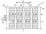
- FIG. 1 shows a development view of the tread 12 of the pneumatic tire 10.
- the tread 12 of the pneumatic tire 10 of the present embodiment has a bilaterally symmetric shape with a tire equatorial plane CL (a plane that bisects the pneumatic tire 10 at the center of the tread 12 in the tire width direction) interposed therebetween.
- the tire ground contact edge 12E of the tread 12 is a pneumatic tire 10 mounted on a standard rim stipulated in JATMA YEAR BOOK (Japan Automobile Tire Association Standard, 2012 version), and applicable size and ply in JATMA YEAR BOOK. This is when the maximum load capacity is loaded with 100% internal pressure of the air pressure (maximum air pressure) corresponding to the maximum load capacity in the rating (internal pressure-load capacity in bold load table).
- JATMA YEAR BOOK Japanese Automobile Tire Association Standard, 2012 version
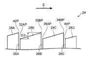
- the rotational direction of the pneumatic tire 10 is predetermined. In the drawing, this rotational direction is indicated by an arrow S, and the tire width direction orthogonal thereto is indicated by an arrow W.
- the circumferential direction of the pneumatic tire 10 is the rotational direction and the opposite direction.
- the height of the land portion (block) corresponds to the distance from the tire shaft. If the distance from the tire shaft is far, the height of the block is high. If the distance from the tire shaft is short, the height of the block is high. Becomes lower.
- three tire circumferential grooves 20A, 20B, and 20C are formed along the tire circumferential direction.
- the tire circumferential groove 20B is formed on the tire equatorial plane CL.
- the tire circumferential grooves 20A and 20C are formed at symmetrical positions with the tire circumferential groove 20B interposed therebetween.
- lug grooves 22 are formed in the tread 12 along the tire width direction. A plurality of lug grooves 22 are formed at predetermined intervals in the tire circumferential direction.
- the tread 12 is partitioned by tire circumferential grooves 20A to 20C and lug grooves 22 to form a plurality of blocks 24.
- sipes 26A to 26C extending in the tire width direction are formed.
- the sipes 26A to 26C are formed in a zigzag shape having an amplitude in the tire circumferential direction.
- the area of the block 24 is divided by the sipes 26A to 26C.
- the sipes 26A to 26C have a groove width that is closed when contacted, and are formed in one block 24 at intervals in the tire circumferential direction.
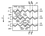
- the block 24 is divided into four small block portions 28A to 28D by the sipes 26A to 26C.
- the sipes 26A to 26C are also zigzag-shaped in the tire radial direction, and are so-called three-dimensional sipes (3D sipes).
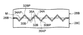
- the small block portion 28B has a convex portion 30 that protrudes from the small block portion 28B on the basis of the extending direction of the sipe 26A, that is, convex in the tire circumferential direction when viewed in plan. ing. Moreover, it has the recessed part 32 which becomes concave with respect to the small block part 28B on the basis of the extending direction of the sipe 26A, ie, becomes concave in the tire circumferential direction when seen in a plan view.
- the convex part 30 and the concave part 32 on the stepping end side of the small block part 28B are defined as a convex part 30B and a concave part 32B, respectively, and the convex part 30 and the concave part 32 on the kick-out end side are defined as a convex part 30A and a concave part 32A, respectively.
- the convex portions 30A and 30B are collectively referred to as the convex portion 30, and the concave portions 32A and 32B are collectively referred to as the concave portion 32. As shown in FIG.
- the convex portion 30 and the concave portion 32 are arranged from the small block portion 28 ⁇ / b> B to the tire.
- a portion protruding in the circumferential direction is referred to as a convex portion 30, and a portion entering (retracting from) the small block portion 28 ⁇ / b> B side is referred to as a concave portion 32.
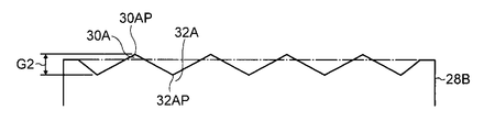
- the vertices of the convex portions 30A and 30B are the vertices 30AP and 30BP, respectively, and the bending points of the valleys of the concave portions 32A and 32B are the valley points 32AP and 32BP.
- the block height in the small block portion 28B is not uniform, and the height changes gently and has a height difference.
- the block height in the small block portion 28B is the highest at the vertex 30BP and the lowest at the valley point 32AP.
- the slope is inclined so that the height gradually decreases from the vertex 30BP toward the valley point 32AP.
- the slope is inclined so that the height gradually decreases from the vertex 30AP to the valley point 32BP.
- the height of the vertex 34AP formed along the sipe 26B is lower than the vertex 30BP, and the height of the valley point 32AP is lower than the valley point BP. Further, the height of the vertex 30AP is higher than the valley point BP.
- FIG. 5B is a plan view of the small block portion 28B
- FIGS. 5A and 5C are side development views of edge portions along the sipes 26A and 26B.
- the upper part of the edge along the sipe 26A of the small block portion 28B has an inclination that gradually decreases from the convex portion 30A toward the adjacent concave portion 32A.
- the upper edge portion along the sipe 26B also has a slope that gradually decreases from the convex portion 30B toward the adjacent concave portion 32B.
- the height difference G1 between the vertex 30BP and the valley point 32BP is preferably in the range of 0.1 mm to 1.0 mm, and more preferably in the range of 0.25 mm to 0.5 mm.
- the height difference G2 between the apex 30AP and the valley point 32AP is also preferably in the range of 0.1 mm to 1.0 mm, and more preferably in the range of 0.25 mm to 0.5 mm.
- the height difference G3 (see FIG. 4A) between the vertex 30BP and the valley point 32AP is preferably in the range of 0.2 mm to 2.0 mm, and more preferably in the range of 0.5 mm to 1.0 mm.
- the height difference G4 (see FIG. 4B) between the vertex 30AP and the valley point 32BP is preferably in the range of 0.05 mm to 0.5 mm.
- the small block portion 28B and the small block portion 28C have the same shape.
- the portions corresponding to the convex portions 30A and 30B, the concave portions 32A and 32B, the apexes 30AP and 30BP, and the valley points 32AP and 32BP of the small block portion 28B are respectively provided with the convex portions 34A and 34B and the concave portions 36A and 36B.
- the small block portion 28A has substantially the same shape as the portion closer to the small block portion 28C than the line M of the small block portion 28B.
- the edge portion along the lug groove 22 of the small block portion 28A is linear.
- the portions corresponding to the convex portion 30B, the concave portion 32B, the vertex 30BP, and the valley point 32BP of the small block portion 28B are defined as a convex portion 42, a concave portion 40, a vertex 42P, and a valley point 40P, respectively.
- the small block portion 28D has substantially the same shape as the portion on the small block portion 28A side from the line M of the small block portion 28B.
- the edge portion along the lug groove 22 of the small block portion 28D is linear.
- portions corresponding to the convex portion 30A, the concave portion 32A, the vertex 30AP, and the valley point 32AP of the small block portion 28B are defined as a convex portion 46, a concave portion 44, a vertex 46P, and a valley point 44P, respectively.
- FIG. 6A shows a plan view of a portion adjacent to the sipe 26B of the small block portions 28B and 28C.
- FIG. 6B shows a diagram showing the height when the edge portion along the sipe 26B is viewed from the tire circumferential direction.
- steps are formed in the tire width direction W due to the height difference of the convex portion 30B, the concave portion 32B, the convex portion 34A, and the concave portion 36A.
- the small block portion 28A and the small block portion 28B arranged on both sides of the sipe 26A there is a difference in height between the convex portion 42, the concave portion 40, the convex portion 30A, and the concave portion 32A.
- the height of the convex portion 34B, the concave portion 36B, the convex portion 46, and the concave portion 44 is increased in the tire width direction W.
- a step is formed.
- the convex portion arranged on the sipe kicking side is higher than the convex portion arranged on the stepping side.
- positioned at the kicking side of a sipe is arrange
- positioned at the stepping-in side of the sipe is a kicking end in one small block part. It will be arranged in.
- a small block in the tire circumferential direction, a cross section taken along the line AA of the block 24 connecting the vertex 42P, valley point 32A, vertex 30BP, valley point 36AP, vertex 34BP, and valley point 44P, as shown in FIG. 4A, a small block
- the stepping ends of the portions 28A to 28D are high.
- the small block portions 28A to 28D are kicked. The protruding end is high.
- Each block 24 of the pneumatic tire 10 has zigzag sipe 26A to 26C extending in the tire width direction, and includes a convex portion 42 and a concave portion 40, a convex portion 30 and a concave portion 32, and a convex portion 34 along the same sipe.
- the convex part 36, the convex part 46, and the recessed part 44 the convex part is higher than the recessed part. Accordingly, the contact pressure at the edge portion of the convex portion, which is relatively high, is increased due to the difference in height between the convex portion and the concave portion, and the grip performance can be improved.
- the convex portion on the sipe kicking side is higher than the convex portion on the stepping side. Therefore, there is also a difference in height between the height of the convex portion arranged on the stepping side across the sipes 26A to 26C and the height of the convex portion of the block portion on the kicking side, and the convex portion on the kicking side becomes high. ing. As a result, the contact pressure at the edge portion of the protrusion on the kicking side across the sipes 26A to 26C is increased, and the grip performance can be further improved. Moreover, the grip performance on a snowy road can be improved by the scratching effect of the edge part of the convex part on the kick-out side.
- the convex portions and concave portions of the small block portions 28A to 28D arranged on both sides of the sipes 26A to 26C are the convex portions on the sipe kicking side, although it is higher than the convex part on the stepping side, the height of the convex part may be the same on the stepping side and the kicking side of the sipe.
- the zigzag three-dimensional sipe in the tire radial direction is described as an example of the sipe, but the sipe may not be a three-dimensional sipe.
- the rigidity of the small block portion 28 can be ensured.
- the sipe is described as an example of the tire width direction groove, but the tire width direction groove of the present invention may be a narrow groove or a lug groove instead of a sipe. Moreover, although this embodiment demonstrated the example in which the sipe was extended in parallel with the tire width direction, the sipe may be extended so that it may have an angle with respect to the tire width direction.
- the tire width direction groove of the present invention is formed in a rib that is a land portion continuous in the tire circumferential direction. It may be a thing.
- the convex part and recessed part of this invention are not limited to what is formed in a zigzag shape, Other forms But you can.
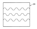
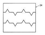
- FIG. 7A it may be wavy, and as shown in FIG. 7B, it may have a shape having a portion parallel to the tire width direction between the convex portion and the concave portion.
- the small block portions 28B and 28C have been described with respect to the example in which the convex portions and the concave portions on both sides of the step-in end and the kick-out end have a height difference, but only the convex portions and the concave portions on one side. It may have a height difference.
- the block kick-out side end side from the line M of the small block portion 28 may be flat at the same height.
- the corresponding portion has the same height, but the small block portion adjacent in the tire circumferential direction changes to a height for each small block portion. May be attached.
- a high small block portion whose overall block height is increased and a low block portion whose overall block height is decreased may be alternately arranged. In this way, by applying a change, the height difference between adjacent small block portions is increased, and the contact pressure can be further increased.
- the pneumatic tire whose rotation direction is predetermined is described, but the present invention may be applied to a pneumatic tire whose rotation direction is not determined.
- the pneumatic tire of the present invention has been described by taking a studless tire as an example.
- the present invention is not limited to a studless tire, and can be applied to other pneumatic tires.
- a pneumatic tire provided with the tread pattern of the present embodiment shown in FIG. 1 was mounted on a vehicle, and acceleration and braking distance were measured.
- Level difference between the apex of the convex part and the valley point of the concave part arranged on both sides across the same sipe hereinafter simply referred to as “step"
- step the height of the peak point of the convex part adjacent to the same sipe and the valley point of the concave part
- level difference is changed, and other conditions are the same.
- the tire size, test conditions, and method are as follows. The test results are as shown in Table 1.
Abstract
In the present invention, a plurality of land sections (24) that are divided by circumferential direction grooves are formed in a tread (12). The land sections (24) are divided into a plurality of block sections (28A—28D) by a plurality of tire-width-direction grooves (26A—26C) that extend in a tire-width direction. As seen in plan view, the block sections (28A-28D) have concavities (32A, 32B, 36A, 36B, 40, 44) and protrusions (30A, 30B, 34A, 34B, 42, 46). The block height of the protrusions (30A, 30B, 34A, 34B, 42, 46) is taller than the block height of the concavities (32A, 32B, 36A, 36B, 40, 44) where the tire-width-direction grooves (26A, 26B, 26C) are interposed.
Description
本発明は、トレッド面に陸部を有する空気入りに関する。
The present invention relates to pneumatic having a land portion on a tread surface.
一般的に、空気入りタイヤでは、エッジ効果を発揮させるために、トレッドには複数の溝が形成されている(例えば、特許文献1参照)。そして、溝の本数を多く形成したり、溝の方向を変えてジグザグ形状にしたりして、溝の長さを長くすることにより、エッジ効果を高めることが行われている。しかしながら、トレッドの陸部において溝密度を増加させると、陸部の剛性が低下して倒れ込んでしまい、グリップ力を効果的に得ることが難しい。
Generally, in a pneumatic tire, a plurality of grooves are formed in the tread in order to exert an edge effect (see, for example, Patent Document 1). Then, the edge effect is enhanced by increasing the length of the groove by increasing the number of grooves or by changing the direction of the groove to form a zigzag shape. However, when the groove density is increased in the land portion of the tread, the rigidity of the land portion is lowered and falls down, and it is difficult to obtain a grip force effectively.
本発明は上記事実を考慮してなされたものであり、溝長さが同じでもエッジ効果を高めてグリップ性能を向上させた空気入りタイヤを提供することを目的とする。
The present invention has been made in consideration of the above facts, and an object of the present invention is to provide a pneumatic tire having an improved edge effect and improved grip performance even with the same groove length.
本発明の第1の態様に係る空気入りタイヤは、トレッドに形成され、タイヤ周方向溝で区画された陸部と、前記陸部を区分し、タイヤ幅方向に延びる複数のタイヤ幅方向溝と、前記タイヤ幅方向溝によって区画形成されたブロック部と、前記ブロック部の一部を構成し、前記タイヤ幅方向溝を挟んで一方側及び他方側の各々の前記ブロック部に形成され、前記タイヤ幅方向溝の延在方向を基準として平面視で前記一方側の前記ブロック部から突出する凸部と該凸部に対向し前記他方側の前記ブロック部で凹となる凹部、及び、前記一方側の前記ブロック部で凹となる凹部と該凹部に対向し前記他方側の前記ブロック部から突出する凸部とを有し、前記凸部のブロック高さが前記タイヤ幅方向溝を挟んだ位置の前記凹部のブロック高さよりも高く形成されている。
The pneumatic tire according to the first aspect of the present invention includes a land portion formed in a tread and defined by a tire circumferential groove, and a plurality of tire width direction grooves that divide the land portion and extend in the tire width direction. A block portion partitioned by the tire width direction groove, and a part of the block portion, and formed on each of the block portions on one side and the other side of the tire width direction groove, the tire A convex portion protruding from the block portion on the one side in a plan view with respect to the extending direction of the width direction groove, a concave portion facing the convex portion and recessed at the block portion on the other side, and the one side A concave portion that is concave in the block portion and a convex portion that projects from the block portion on the other side facing the concave portion, and the block height of the convex portion is at a position sandwiching the groove in the tire width direction. Than the block height of the recess It is Ku formation.
本発明の第1の態様に係る空気入りタイヤは、トレッドに複数のタイヤ周方向溝で区画された陸部を有している。陸部は、タイヤ幅方向に延びる複数のタイヤ幅方向溝により区分されている。
The pneumatic tire according to the first aspect of the present invention has a land portion partitioned by a plurality of tire circumferential grooves on the tread. The land portion is divided by a plurality of tire width direction grooves extending in the tire width direction.
ここで「陸部」とは、トレッドにおいて主に踏面を形成する部分であり、少なくともタイヤ周方向溝によって区画されているリブやブロックを意味している。また、タイヤ幅方向溝は、接地時に溝が閉鎖しないラグ溝の他に、接地時に溝が閉鎖する所謂サイプ等の細溝も含んでいる。また、ここでの「区分」は、平面視において完全に分割されている場合の他、完全に分割されずに一部が連続している場合を含んでいる。さらに、「タイヤ幅方向に延びる」とは、タイヤ幅方向に平行に延びる場合の他、タイヤ幅方向の成分をもって延びる方向をいう。
Here, the “land portion” is a portion that mainly forms a tread surface in the tread, and means a rib or a block that is partitioned by at least a tire circumferential groove. Further, the tire width direction groove includes a thin groove such as a so-called sipe in which the groove is closed at the time of contact in addition to the lug groove that is not closed at the time of the contact. Further, the “section” here includes not only the case of being completely divided in a plan view but also the case of being partly continuous without being completely divided. Furthermore, “extending in the tire width direction” means a direction extending with a component in the tire width direction in addition to the case of extending in the tire width direction.
第1の態様に係る空気入りタイヤでは、一対のブロック部は、タイヤ幅方向溝によって区画形成され、タイヤ幅方向溝を挟んで一方側及び他方側には平面視でタイヤ幅方向溝の延在方向に対して凸となる凸部及び凹となる凹部が各々形成されている。凸部と凹部は、一方側のブロック部から突出する凸部と該凸部に対向し他方側の前記ブロック部で凹となる凹部、及び、一方側のブロック部で凹となる凹部と該凹部に対向し他方側のブロック部から突出する凸部を含んでいる。そして、凸部のブロック高さは、タイヤ幅方向溝を挟んだ位置の凹部のブロック高さよりも高く形成されている。
In the pneumatic tire according to the first aspect, the pair of block portions are defined by the tire width direction groove, and the tire width direction groove extends in plan view on one side and the other side across the tire width direction groove. A convex portion that is convex with respect to the direction and a concave portion that is concave are formed. The convex part and the concave part are a convex part protruding from the block part on one side, a concave part facing the convex part and recessed in the block part on the other side, and a concave part and concave part in the concave part on the one side block part. Convex part which protrudes from the block part of the other side which opposes. And the block height of a convex part is formed higher than the block height of the recessed part of the position which pinched | interposed the tire width direction groove | channel.
ここで、凸部は、タイヤ幅方向溝の延在方向を基準にして陸部がブロック部から突出している部分であり、凹部は逆に陸部がブロック部内へ後退している部分である。凸部と凹部が連続して形成される波状の場合には、当該波状の部分の振幅の中央位置を境にして凸部と凹部とを区分する。
Here, the convex portion is a portion where the land portion protrudes from the block portion on the basis of the extending direction of the tire width direction groove, and the concave portion is a portion where the land portion retreats into the block portion. In the case of a wavy shape in which the convex portion and the concave portion are continuously formed, the convex portion and the concave portion are separated from each other with the central position of the amplitude of the wavy portion as a boundary.
上記構成によれば、タイヤ幅方向溝を挟んだ両側の凸部と凹部との間に高低差があるので、凸部のエッジが相対的に高くなる。したがって、凸部の接地圧が高まりグリップ性能を向上させることができる。また、凸部のエッジは、タイヤ周方向及びタイヤ幅方向の成分を有しているので、直進時だけでなく、旋回時のグリップ性能も向上させることができる。
According to the above configuration, since there is a height difference between the convex portions and the concave portions on both sides across the tire width direction groove, the edges of the convex portions are relatively high. Therefore, the contact pressure of the convex portion is increased and the grip performance can be improved. Further, since the edge of the convex portion has components in the tire circumferential direction and the tire width direction, it is possible to improve the grip performance not only when going straight but also when turning.
本発明の第2の態様に係る空気入りタイヤは、前記タイヤ幅方向溝の蹴り出し側の前記凸部は、踏み込み側の凸部よりもブロック高さが高い、ことを特徴とする。
The pneumatic tire according to the second aspect of the present invention is characterized in that the protruding portion on the kicking side of the groove in the tire width direction has a higher block height than the protruding portion on the stepping side.
第2の態様に係る空気入りタイヤでは、ブロック高さについて、タイヤ幅方向溝の蹴り出し側の凸部が、踏み込み側の凸部よりも高い。したがって、タイヤ幅方向溝の蹴り出し側の凸部、すなわち、ブロック部の踏み込み端側の凸部のエッジ部分の接地圧が高くなり、引っかき効果により、特に雪上でのグリップ性能をさらに向上させることができる。
In the pneumatic tire according to the second aspect, with respect to the block height, the protrusion on the kicking side of the groove in the tire width direction is higher than the protrusion on the stepping side. Therefore, the contact pressure of the protruding portion of the tire width direction groove, that is, the edge portion of the protruding portion on the stepping end side of the block portion is increased, and the grip performance on snow is further improved by the scratching effect. Can do.
本発明の第3の態様に係る空気入りタイヤは、1のブロック部内には、タイヤ周方向の両側に各々前記凸部が形成され、前記ブロック部の踏み込み端側の前記凸部は、蹴り出し端側の凸部よりもブロック高さが高い、ことを特徴とする。
In the pneumatic tire according to the third aspect of the present invention, the convex portion is formed on each side of the tire circumferential direction in one block portion, and the convex portion on the stepping end side of the block portion is kicked out. The block height is higher than the convex portion on the end side.
第3の態様に係る空気入りタイヤでは、タイヤ周方向の両側に配置された凸部の高さ間にも高低差があり、踏み込み端側の凸部が高くなっている。したがって、ブロック部の踏み込み端側の凸部エッジ部分が高くなり、グリップ性能をさらに向上させることができる。
In the pneumatic tire according to the third aspect, there is a difference in height between the heights of the convex portions arranged on both sides in the tire circumferential direction, and the convex portion on the stepping end side is high. Therefore, the convex edge portion on the stepping end side of the block portion becomes high, and the grip performance can be further improved.
本発明の第4の態様に係る空気入りタイヤは、前記タイヤ幅方向溝が、タイヤ周方向に振幅を有するジグザグ状である、ことを特徴とする。
The pneumatic tire according to the fourth aspect of the present invention is characterized in that the tire width direction groove has a zigzag shape having an amplitude in the tire circumferential direction.
このように、ジグザグ状のタイヤ幅方向溝とすることにより、1つのブロック部内において凸部と凹部とが交互に繰り返し形成され、両者の高低差によりグリップ性能をより向上させることができる。
Thus, by forming a zigzag-shaped groove in the tire width direction, convex portions and concave portions are alternately and repeatedly formed in one block portion, and the grip performance can be further improved by the difference in height between the two.
本発明の第5の態様に係る空気入りタイヤは、前記タイヤ幅方向溝が、接地した際に閉鎖するサイプである、ことを特徴とする。
A pneumatic tire according to a fifth aspect of the present invention is characterized in that the tire width direction groove is a sipe that closes when grounded.
このように、サイプで区画される凸部の高さを凹部の高さよりも高くすることにより、比較的陸部の剛性低下を生じさせ難くエッジ効果を発揮させるサイプを用いて、効果的にグリップ性能を向上させることができる。
In this way, by making the height of the convex part partitioned by the sipe higher than the height of the concave part, it is possible to grip effectively by using a sipe that exhibits an edge effect that is relatively unlikely to cause a decrease in rigidity of the land part. Performance can be improved.
本発明は上記構成としたので、陸部の溝長さが同じでもエッジ効果を高めてグリップ性能を向上させることができる。
Since the present invention has the above configuration, the edge effect can be enhanced and the grip performance can be improved even if the groove length of the land portion is the same.
以下、図面にしたがって、本発明の一実施形態に係る空気入りタイヤ10について説明する。本実施形態では、雪路でグリップ力を発揮するスタッドレスタイヤを例に挙げて空気入りタイヤ10を説明する。
Hereinafter, a pneumatic tire 10 according to an embodiment of the present invention will be described with reference to the drawings. In the present embodiment, the pneumatic tire 10 will be described by taking a studless tire that exhibits grip force on a snowy road as an example.
図1には、空気入りタイヤ10のトレッド12の展開図が示されている。本実施形態の空気入りタイヤ10のトレッド12は、タイヤ赤道面CL(トレッド12のタイヤ幅方向中央で空気入りタイヤ10を2分する面)を挟んで左右対称形状とされている。なお、トレッド12のタイヤ接地端12Eは、空気入りタイヤ10をJATMA YEAR BOOK(日本自動車タイヤ協会規格、2012年度版)に規定されている標準リムに装着し、JATMA YEAR BOOKでの適用サイズ・プライレーティングにおける最大負荷能力(内圧-負荷能力対応表の太字荷重)に対応する空気圧(最大空気圧)の100%の内圧を充填し、最大負荷能力を負荷したときのものである。使用地又は製造地において、TRA規格、ETRTO規格が適用される場合は各々の規格に従う。
FIG. 1 shows a development view of the tread 12 of the pneumatic tire 10. The tread 12 of the pneumatic tire 10 of the present embodiment has a bilaterally symmetric shape with a tire equatorial plane CL (a plane that bisects the pneumatic tire 10 at the center of the tread 12 in the tire width direction) interposed therebetween. The tire ground contact edge 12E of the tread 12 is a pneumatic tire 10 mounted on a standard rim stipulated in JATMA YEAR BOOK (Japan Automobile Tire Association Standard, 2012 version), and applicable size and ply in JATMA YEAR BOOK. This is when the maximum load capacity is loaded with 100% internal pressure of the air pressure (maximum air pressure) corresponding to the maximum load capacity in the rating (internal pressure-load capacity in bold load table). When the TRA standard or ETRTO standard is applied at the place of use or manufacturing, the respective standards are followed.
また、この空気入りタイヤ10は、回転方向があらかじめ決められている。図面においてこの回転方向を矢印Sで示し、これと直交するタイヤ幅方向を矢印Wでそれぞれ示す。なお、空気入りタイヤ10の周方向は、回転方向及びその反対方向となる。
Further, the rotational direction of the pneumatic tire 10 is predetermined. In the drawing, this rotational direction is indicated by an arrow S, and the tire width direction orthogonal thereto is indicated by an arrow W. The circumferential direction of the pneumatic tire 10 is the rotational direction and the opposite direction.
また、陸部(ブロック)の高さは、タイヤ軸からの距離に対応するものであり、タイヤ軸からの距離が遠ければブロックの高さが高く、タイヤ軸からの距離が近ければブロックの高さが低くなる。
The height of the land portion (block) corresponds to the distance from the tire shaft. If the distance from the tire shaft is far, the height of the block is high. If the distance from the tire shaft is short, the height of the block is high. Becomes lower.
本実施形態の空気入りタイヤ10のトレッド12には、タイヤ周方向に沿って3本のタイヤ周方向溝20A、20B、20Cが形成されている。タイヤ周方向溝20Bはタイヤ赤道面CL上に形成されている。タイヤ周方向溝20A、20Cは、タイヤ周方向溝20Bを挟んで対称位置に形成されている。また、トレッド12には、タイヤ幅方向に沿ってラグ溝22が形成されている。ラグ溝22は、タイヤ周方向に所定間隔で複数形成されている。
In the tread 12 of the pneumatic tire 10 of the present embodiment, three tire circumferential grooves 20A, 20B, and 20C are formed along the tire circumferential direction. The tire circumferential groove 20B is formed on the tire equatorial plane CL. The tire circumferential grooves 20A and 20C are formed at symmetrical positions with the tire circumferential groove 20B interposed therebetween. Further, lug grooves 22 are formed in the tread 12 along the tire width direction. A plurality of lug grooves 22 are formed at predetermined intervals in the tire circumferential direction.
トレッド12には、タイヤ周方向溝20A~20C、及びラグ溝22で区画されて、複数のブロック24が形成されている。ブロック24には、タイヤ幅方向に延出するサイプ26A~26Cが形成されている。サイプ26A~26Cは、タイヤ周方向に振幅を有するジグザグ状とされている。サイプ26A~26Cによりブロック24の領域が区分されている。サイプ26A~26Cは、接地時に閉鎖される程度の溝幅を有し、1のブロック24内にタイヤ周方向に間隔をあけて形成されている。サイプ26A~26Cにより、ブロック24は4つの小ブロック部28A~28Dに区画されている。図3に示されるように、サイプ26A~26Cは、タイヤ径方向にもジグザグ状とされており、所謂3次元サイプ(3Dサイプ)となっている。
The tread 12 is partitioned by tire circumferential grooves 20A to 20C and lug grooves 22 to form a plurality of blocks 24. In the block 24, sipes 26A to 26C extending in the tire width direction are formed. The sipes 26A to 26C are formed in a zigzag shape having an amplitude in the tire circumferential direction. The area of the block 24 is divided by the sipes 26A to 26C. The sipes 26A to 26C have a groove width that is closed when contacted, and are formed in one block 24 at intervals in the tire circumferential direction. The block 24 is divided into four small block portions 28A to 28D by the sipes 26A to 26C. As shown in FIG. 3, the sipes 26A to 26C are also zigzag-shaped in the tire radial direction, and are so-called three-dimensional sipes (3D sipes).
図2に示すように、小ブロック部28Bは、サイプ26Aの延在方向を基準として小ブロック部28Bから突出する、すなわち、平面視した場合にタイヤ周方向に凸となる凸部30を有している。また、サイプ26Aの延在方向を基準として小ブロック部28Bに対して凹となる、すなわち、平面視した場合にタイヤ周方向に凹となる凹部32を有している。小ブロック部28Bの踏み込み端側の凸部30、凹部32を、各々凸部30B、凹部32Bとし、蹴り出し端側の凸部30、凹部32を各々凸部30A、凹部32Aとする。凸部30A、30Bをまとめて凸部30といい、凹部32A、32Bをまとめて凹部32という。凸部30と凹部32は、図2に示すように、サイプ26A、26Bの振幅Aに対してタイヤ周方向の中心位置のラインMを仮定した場合、このラインMよりも小ブロック部28Bからタイヤ周方向に突出している部分を凸部30とし、小ブロック部28B側に入り込んでいる(後退している)部分を凹部32とする。以下、平面視した場合の小ブロック部における凸部、凹部について同様である。また、凸部30A、30Bの頂点を、各々、頂点30AP、30BPとし、凹部32A、32Bの谷の屈曲点を谷点32AP、32BPとする。
As shown in FIG. 2, the small block portion 28B has a convex portion 30 that protrudes from the small block portion 28B on the basis of the extending direction of the sipe 26A, that is, convex in the tire circumferential direction when viewed in plan. ing. Moreover, it has the recessed part 32 which becomes concave with respect to the small block part 28B on the basis of the extending direction of the sipe 26A, ie, becomes concave in the tire circumferential direction when seen in a plan view. The convex part 30 and the concave part 32 on the stepping end side of the small block part 28B are defined as a convex part 30B and a concave part 32B, respectively, and the convex part 30 and the concave part 32 on the kick-out end side are defined as a convex part 30A and a concave part 32A, respectively. The convex portions 30A and 30B are collectively referred to as the convex portion 30, and the concave portions 32A and 32B are collectively referred to as the concave portion 32. As shown in FIG. 2, when assuming the line M at the center position in the tire circumferential direction with respect to the amplitude A of the sipes 26 </ b> A and 26 </ b> B, the convex portion 30 and the concave portion 32 are arranged from the small block portion 28 </ b> B to the tire. A portion protruding in the circumferential direction is referred to as a convex portion 30, and a portion entering (retracting from) the small block portion 28 </ b> B side is referred to as a concave portion 32. Hereinafter, the same applies to the convex portions and the concave portions in the small block portion in plan view. The vertices of the convex portions 30A and 30B are the vertices 30AP and 30BP, respectively, and the bending points of the valleys of the concave portions 32A and 32B are the valley points 32AP and 32BP.
小ブロック部28B内のブロック高さは均一ではなく、緩やかに高さが変化して高低差を有している。小ブロック部28B内のブロック高さは、頂点30BPが最も高く、谷点32APが最も低くなっている。図4Aに示すように、頂点30BPから頂点30BPとタイヤ周方向で向き合う谷点32APにかけては、頂点30BPから谷点32APに向かって徐々に高さが低くなるように傾斜している。また、図4Bに示すように、頂点30APから頂点30APとタイヤ周方向で向き合う谷点32BPにかけても、頂点30APから谷点32BPに向かって徐々に高さが低くなるように傾斜している。また、図6Bに示すように、サイプ26Bに沿って形成されている頂点34APの高さは頂点30BPよりも低く、谷点32APの高さは谷点BPよりも低くなっている。また、頂点30APの高さは谷点BPよりも高くなっている。
The block height in the small block portion 28B is not uniform, and the height changes gently and has a height difference. The block height in the small block portion 28B is the highest at the vertex 30BP and the lowest at the valley point 32AP. As shown in FIG. 4A, from the vertex 30BP to the valley point 32AP facing the vertex 30BP in the tire circumferential direction, the slope is inclined so that the height gradually decreases from the vertex 30BP toward the valley point 32AP. Further, as shown in FIG. 4B, even from the vertex 30AP to the valley point 32BP facing the vertex 30AP in the tire circumferential direction, the slope is inclined so that the height gradually decreases from the vertex 30AP to the valley point 32BP. 6B, the height of the vertex 34AP formed along the sipe 26B is lower than the vertex 30BP, and the height of the valley point 32AP is lower than the valley point BP. Further, the height of the vertex 30AP is higher than the valley point BP.
図5Bには、小ブロック部28Bの平面図が示され、、図5A、図5Cには、サイプ26A、26Bに沿ったエッジ部分の側面展開図が示されている。図5Aに示されるように、小ブロック部28Bのサイプ26Aに沿ったエッジ上部は、凸部30Aから隣り合う凹部32Aに向かって徐々に低くなる傾斜となっている。また、図5Cに示されるように、サイプ26Bに沿ったエッジ上部についても、凸部30Bから隣り合う凹部32Bに向かって徐々に低くなる傾斜となっている。
5B is a plan view of the small block portion 28B, and FIGS. 5A and 5C are side development views of edge portions along the sipes 26A and 26B. As shown in FIG. 5A, the upper part of the edge along the sipe 26A of the small block portion 28B has an inclination that gradually decreases from the convex portion 30A toward the adjacent concave portion 32A. Further, as shown in FIG. 5C, the upper edge portion along the sipe 26B also has a slope that gradually decreases from the convex portion 30B toward the adjacent concave portion 32B.
頂点30BPと谷点32BPの高低差G1は、0.1mm~1.0mmの範囲であることが好ましく、0.25mm~0.5mmの範囲であることがより好ましい。また、頂点30APと谷点32APの高低差G2も、0.1mm~1.0mmの範囲であることが好ましく、0.25mm~0.5mmの範囲であることがより好ましい。さらに、頂点30BPと谷点32APの高低差G3(図4A参照)は、0.2mm~2.0mmの範囲であることが好ましく、0.5mm~1.0mmの範囲であることがより好ましい。また、頂点30APと谷点32BPの高低差G4(図4B参照)は、0.05mm~0.5mmの範囲であることが好ましい。
The height difference G1 between the vertex 30BP and the valley point 32BP is preferably in the range of 0.1 mm to 1.0 mm, and more preferably in the range of 0.25 mm to 0.5 mm. Further, the height difference G2 between the apex 30AP and the valley point 32AP is also preferably in the range of 0.1 mm to 1.0 mm, and more preferably in the range of 0.25 mm to 0.5 mm. Further, the height difference G3 (see FIG. 4A) between the vertex 30BP and the valley point 32AP is preferably in the range of 0.2 mm to 2.0 mm, and more preferably in the range of 0.5 mm to 1.0 mm. Further, the height difference G4 (see FIG. 4B) between the vertex 30AP and the valley point 32BP is preferably in the range of 0.05 mm to 0.5 mm.
小ブロック部28Bと小ブロック部28Cとは、同一形状とされている。小ブロック部28Cでは、小ブロック部28Bの凸部30A、30B、凹部32A、32B、頂点30AP、30BP、谷点32AP、32BPに対応する部分を、各々、凸部34A、34B、凹部36A、36B、頂点34AP、34BP、谷点36AP、36BPとする。
The small block portion 28B and the small block portion 28C have the same shape. In the small block portion 28C, the portions corresponding to the convex portions 30A and 30B, the concave portions 32A and 32B, the apexes 30AP and 30BP, and the valley points 32AP and 32BP of the small block portion 28B are respectively provided with the convex portions 34A and 34B and the concave portions 36A and 36B. , Vertices 34AP and 34BP, valley points 36AP and 36BP.
小ブロック部28Aは、小ブロック部28BのラインMよりも小ブロック部28C側の部分と略同一形状とされている。小ブロック部28Aのラグ溝22に沿ったエッジ部分は直線状とされている。小ブロック部28Aでは、小ブロック部28Bの凸部30B、凹部32B、頂点30BP、谷点32BPに対応する部分を、各々、凸部42、凹部40、頂点42P、谷点40Pとする。
The small block portion 28A has substantially the same shape as the portion closer to the small block portion 28C than the line M of the small block portion 28B. The edge portion along the lug groove 22 of the small block portion 28A is linear. In the small block portion 28A, the portions corresponding to the convex portion 30B, the concave portion 32B, the vertex 30BP, and the valley point 32BP of the small block portion 28B are defined as a convex portion 42, a concave portion 40, a vertex 42P, and a valley point 40P, respectively.
小ブロック部28Dは、小ブロック部28BのラインMよりも小ブロック部28A側の部分と略同一形状とされている。小ブロック部28Dのラグ溝22に沿ったエッジ部分は直線状とされている。小ブロック部28Dでは、小ブロック部28Bの凸部30A、凹部32A、頂点30AP、谷点32APに対応する部分を、各々、凸部46、凹部44、頂点46P、谷点44Pとする。
The small block portion 28D has substantially the same shape as the portion on the small block portion 28A side from the line M of the small block portion 28B. The edge portion along the lug groove 22 of the small block portion 28D is linear. In the small block portion 28D, portions corresponding to the convex portion 30A, the concave portion 32A, the vertex 30AP, and the valley point 32AP of the small block portion 28B are defined as a convex portion 46, a concave portion 44, a vertex 46P, and a valley point 44P, respectively.
図6Aには、小ブロック部28B、28Cのサイプ26Bを挟んで隣り合う部分の平面図が示されている。図6Bには、サイプ26Bに沿ったエッジ部分をタイヤ周方向から見た高さを示す図が示されている。サイプ26Bを挟んで両側には、凸部30B、凹部32B、凸部34A、凹部36Aの高低差により、タイヤ幅方向Wに段差が形成されている。同様に、サイプ26Aを挟んで両側に配置される小ブロック部28Aと小ブロック部28Bとの間には、凸部42、凹部40、凸部30A、凹部32Aの高低差により、タイヤ幅方向Wに段差が形成されている。さらに、サイプ26Cを挟んで両側に配置される小ブロック部28Cと小ブロック部28Dとの間には、凸部34B、凹部36B、凸部46、凹部44の高低差により、タイヤ幅方向Wに段差が形成されている。
FIG. 6A shows a plan view of a portion adjacent to the sipe 26B of the small block portions 28B and 28C. FIG. 6B shows a diagram showing the height when the edge portion along the sipe 26B is viewed from the tire circumferential direction. On both sides of the sipe 26B, steps are formed in the tire width direction W due to the height difference of the convex portion 30B, the concave portion 32B, the convex portion 34A, and the concave portion 36A. Similarly, between the small block portion 28A and the small block portion 28B arranged on both sides of the sipe 26A, there is a difference in height between the convex portion 42, the concave portion 40, the convex portion 30A, and the concave portion 32A. Are stepped. Further, between the small block portion 28C and the small block portion 28D disposed on both sides of the sipe 26C, the height of the convex portion 34B, the concave portion 36B, the convex portion 46, and the concave portion 44 is increased in the tire width direction W. A step is formed.
サイプ26A~26Cのいずれを挟んで隣り合う小ブロック部についても、サイプの蹴り出し側に配置される凸部が踏み込み側に配置される凸部よりも高くなっている。なお、サイプの蹴り出し側に配置される凸部は、1の小ブロック部内では踏み込み端に配置されており、サイプの踏み込み側に配置される凸部は、1の小ブロック部内では蹴り出し端に配置されていることになる。
In the small block portions adjacent to each other across any of the sipes 26A to 26C, the convex portion arranged on the sipe kicking side is higher than the convex portion arranged on the stepping side. In addition, the convex part arrange | positioned at the kicking side of a sipe is arrange | positioned at the stepping-in end in one small block part, and the convex part arrange | positioned at the stepping-in side of the sipe is a kicking end in one small block part. It will be arranged in.
また、タイヤ周方向においては、頂点42P、谷点32A、頂点30BP、谷点36AP、頂点34BP、及び谷点44Pを結ぶブロック24のA-A線の断面で、図4Aに示すように小ブロック部28A~28Dの踏み込み端が高くなっている。また、谷点40P、頂点30AP、谷点32BP、頂点34AP、谷点36BP、及び頂点46Pを結ぶブロック24のD-D線の断面で、図4Bに示すように小ブロック部28A~28Dの蹴り出し端が高くなっている。
Further, in the tire circumferential direction, a cross section taken along the line AA of the block 24 connecting the vertex 42P, valley point 32A, vertex 30BP, valley point 36AP, vertex 34BP, and valley point 44P, as shown in FIG. 4A, a small block The stepping ends of the portions 28A to 28D are high. Further, in the cross section of the DD line of the block 24 connecting the valley point 40P, the vertex 30AP, the valley point 32BP, the vertex 34AP, the valley point 36BP, and the vertex 46P, as shown in FIG. 4B, the small block portions 28A to 28D are kicked. The protruding end is high.
次に、本実施形態の空気入りタイヤ10の作用を説明する。
Next, the operation of the pneumatic tire 10 of this embodiment will be described.
空気入りタイヤ10の各ブロック24は、タイヤ幅方向に延びるジグザグ状のサイプ26A~26Cを有し、同一のサイプに沿った凸部42と凹部40、凸部30と凹部32、凸部34と凹部36、凸部46と凹部44は、凸部が凹部よりも高くなっている。したがって、凸部と凹部の高低差により、相対的に高くなった凸部のエッジ部分の接地圧が高くなり、グリップ性能を向上させることができる。
Each block 24 of the pneumatic tire 10 has zigzag sipe 26A to 26C extending in the tire width direction, and includes a convex portion 42 and a concave portion 40, a convex portion 30 and a concave portion 32, and a convex portion 34 along the same sipe. As for the recessed part 36, the convex part 46, and the recessed part 44, the convex part is higher than the recessed part. Accordingly, the contact pressure at the edge portion of the convex portion, which is relatively high, is increased due to the difference in height between the convex portion and the concave portion, and the grip performance can be improved.
また、サイプ26A~26Cを挟んで両側に配置されている、各々の小ブロック部28A~28Dの凸部及び凹部は、サイプの蹴り出し側の凸部が、踏み込み側の凸部よりも高い。したがって、サイプ26A~26Cを挟んで踏み込み側に配置された凸部の高さと蹴り出し側のブロック部の凸部の高さとの間にも高低差があり、蹴り出し側の凸部が高くなっている。これにより、サイプ26A~26Cを挟んで蹴り出し側の凸部のエッジ部分の接地圧が高くなり、さらにグリップ性能を向上させることができる。また、蹴り出し側の凸部のエッジ部分の引っかき効果により、雪路でのグリップ性能を向上させることができる。
Further, in the convex portions and concave portions of the small block portions 28A to 28D arranged on both sides of the sipes 26A to 26C, the convex portion on the sipe kicking side is higher than the convex portion on the stepping side. Therefore, there is also a difference in height between the height of the convex portion arranged on the stepping side across the sipes 26A to 26C and the height of the convex portion of the block portion on the kicking side, and the convex portion on the kicking side becomes high. ing. As a result, the contact pressure at the edge portion of the protrusion on the kicking side across the sipes 26A to 26C is increased, and the grip performance can be further improved. Moreover, the grip performance on a snowy road can be improved by the scratching effect of the edge part of the convex part on the kick-out side.
なお、本実施形態では、前述のように、サイプ26A~26Cを挟んで両側に配置されている各々の小ブロック部28A~28Dの凸部及び凹部は、サイプの蹴り出し側の凸部が、踏み込み側の凸部よりも高くなっているが、凸部の高さは、サイプの踏み込み側と蹴り出し側とを同じにしてもよい。
In the present embodiment, as described above, the convex portions and concave portions of the small block portions 28A to 28D arranged on both sides of the sipes 26A to 26C are the convex portions on the sipe kicking side, Although it is higher than the convex part on the stepping side, the height of the convex part may be the same on the stepping side and the kicking side of the sipe.
また、本実施形態では、サイプとしてタイヤ径方向にジグザグ状の3次元サイプを例に説明したが、サイプは3次元サイプでなくてもよい。本実施形態のように3次元サイプを用いることにより、小ブロック部28の剛性を確保することができる。
In this embodiment, the zigzag three-dimensional sipe in the tire radial direction is described as an example of the sipe, but the sipe may not be a three-dimensional sipe. By using a three-dimensional sipe as in this embodiment, the rigidity of the small block portion 28 can be ensured.
また、本実施形態では、タイヤ幅方向溝としてサイプを例に説明したが、本発明のタイヤ幅方向溝は、サイプでなく細溝やラグ溝であってもよい。また、本実施形態では、サイプがタイヤ幅方向と平行に延出されている例について説明したが、サイプは、タイヤ幅方向に対して角度を有するように延出されていてもよい。
In the present embodiment, the sipe is described as an example of the tire width direction groove, but the tire width direction groove of the present invention may be a narrow groove or a lug groove instead of a sipe. Moreover, although this embodiment demonstrated the example in which the sipe was extended in parallel with the tire width direction, the sipe may be extended so that it may have an angle with respect to the tire width direction.
また、本実施形態では、ブロックにタイヤ幅方向溝としてのサイプ26が形成される例について説明したが、本発明のタイヤ幅方向溝は、タイヤ周方向に連続する陸部であるリブに形成されるものであってもよい。
In the present embodiment, the example in which the sipe 26 as the tire width direction groove is formed in the block has been described. However, the tire width direction groove of the present invention is formed in a rib that is a land portion continuous in the tire circumferential direction. It may be a thing.
また、本実施形態では、ジグザグ状のサイプにより凸部及び凹部が形成されている例について説明したが、本発明の凸部及び凹部はジグザグ状に形成されるものに限定されず、他の形態でもよい。例えば、図7Aに示すように、波状でもよいし、図7Bに示すように、凸部と凹部との間にタイヤ幅方向に平行な部分を有する形状にすることもできる。
Moreover, in this embodiment, although the example in which the convex part and the recessed part were formed by the zigzag sipe was demonstrated, the convex part and recessed part of this invention are not limited to what is formed in a zigzag shape, Other forms But you can. For example, as shown in FIG. 7A, it may be wavy, and as shown in FIG. 7B, it may have a shape having a portion parallel to the tire width direction between the convex portion and the concave portion.
さらに、本実施形態では、小ブロック部28B、28Cは、踏み込み端及び蹴り出し端の両側の凸部及び凹部について高低差を有している例について説明したが、片側の凸部及び凹部についてのみ、高低差を有しているものであってもよい。この場合には、例えば、小ブロック部28のラインMよりもブロック蹴り出し側端側をすべて同じ高さの平坦状とすればよい。
Furthermore, in the present embodiment, the small block portions 28B and 28C have been described with respect to the example in which the convex portions and the concave portions on both sides of the step-in end and the kick-out end have a height difference, but only the convex portions and the concave portions on one side. It may have a height difference. In this case, for example, the block kick-out side end side from the line M of the small block portion 28 may be flat at the same height.
また、本実施形態では、小ブロック部28A~28Dの各々について、対応する部分の高さを同一高さとしたが、タイヤ周方向に隣接する小ブロック部について、小ブロック部毎に高さに変化をつけてもよい。例えば、タイヤ周方向に隣り合う小ブロック部28について、全体的にブロック高さを高くした高い小ブロック部と全体的にブロック高さを低くした低いブロック部とを交互に配置してもよい。このように、変化をつけることにより、隣り合う小ブロック部同士の高低差が大きくなり、接地圧をより高めることができる。
Further, in the present embodiment, for each of the small block portions 28A to 28D, the corresponding portion has the same height, but the small block portion adjacent in the tire circumferential direction changes to a height for each small block portion. May be attached. For example, with respect to the small block portions 28 adjacent to each other in the tire circumferential direction, a high small block portion whose overall block height is increased and a low block portion whose overall block height is decreased may be alternately arranged. In this way, by applying a change, the height difference between adjacent small block portions is increased, and the contact pressure can be further increased.
なお、本実施形態では、回転方向が予め定められている空気入りタイヤについて説明したが、本発明は回転方向が決められていない空気入りタイヤに適用してもよい。
In this embodiment, the pneumatic tire whose rotation direction is predetermined is described, but the present invention may be applied to a pneumatic tire whose rotation direction is not determined.
また、本実施形態では、スタッドレスタイヤを例に本発明の空気入りタイヤを説明したが、本発明はスタッドレスタイヤに限定されず、他の空気入りタイヤにも適用することができる。
In this embodiment, the pneumatic tire of the present invention has been described by taking a studless tire as an example. However, the present invention is not limited to a studless tire, and can be applied to other pneumatic tires.
本発明の効果を確かめるために、図1に示す本実施形態のトレッドパターンを備えた空気入りタイヤを車両に装着し、加速度及び制動距離を測定した。同一サイプを挟んで両側に配置される凸部の頂点と凹部の谷点の間の段差(以下単に「段差」という)、同一サイプに沿って隣り合う凸部の頂点と凹部の谷点の高低差(以下単に「高低差」という)を変え、その他の条件は同一としている。タイヤサイズ、試験の条件、方法は以下のとおりである。試験結果は、表1に示す通りである。
In order to confirm the effect of the present invention, a pneumatic tire provided with the tread pattern of the present embodiment shown in FIG. 1 was mounted on a vehicle, and acceleration and braking distance were measured. Level difference between the apex of the convex part and the valley point of the concave part arranged on both sides across the same sipe (hereinafter simply referred to as "step"), the height of the peak point of the convex part adjacent to the same sipe and the valley point of the concave part The difference (hereinafter simply referred to as “level difference”) is changed, and other conditions are the same. The tire size, test conditions, and method are as follows. The test results are as shown in Table 1.
[タイヤサイズ]:225/45R17
[リム]:7.5J
[内圧]:230/230kPa
[荷重]:ドライバーの体重+60kg(588N)
[速度]:加速度測定時:10km/h→35km/h
制動距離測定時:30km/h→0km/h、ABSはONとした。
[試験方法]:加速度測定時:9回分の加速度を平均して指数化した。指数は数値が大きいほどグリップ力が大きいことを示している。
:制動距離測定時:9回分の制動距離を平均して指数化した。指数は数値が小さいほどグリップ力が大きいことを示している。 [Tire size]: 225 / 45R17
[Rim]: 7.5J
[Internal pressure]: 230/230 kPa
[Load]: Weight of driver + 60kg (588N)
[Speed]: During acceleration measurement: 10 km / h → 35 km / h
During braking distance measurement: 30 km / h → 0 km / h, ABS was turned on.
[Test method]: When measuring acceleration: The accelerations of 9 times were averaged and indexed. The index indicates that the greater the value, the greater the grip.
: When measuring the braking distance: The braking distance for nine times was averaged and indexed. The index indicates that the smaller the value, the greater the grip.

表1より、段差が0.15mm~1.00mmの範囲において、段差がない場合よりも優れたグリップ力が得られることを確認できた。また、段差が同じでも高低差がある場合の方が優れたグリップ力が得られることを確認できた。
From Table 1, it was confirmed that in the range where the level difference was 0.15 mm to 1.00 mm, a better grip force was obtained than when there was no level difference. In addition, it was confirmed that an excellent grip force was obtained when there was a difference in height even when the steps were the same.
Claims (5)
- トレッドに形成され、タイヤ周方向溝で区画された陸部と、
前記陸部を区分し、タイヤ幅方向に延びる複数のタイヤ幅方向溝と、
前記タイヤ幅方向溝によって区画形成されたブロック部と、
前記ブロック部の一部を構成し、前記タイヤ幅方向溝を挟んで一方側及び他方側の各々の前記ブロック部に形成され、前記タイヤ幅方向溝の延在方向を基準として平面視で前記一方側の前記ブロック部から突出する凸部と該凸部に対向し前記他方側の前記ブロック部で凹となる凹部、及び、前記一方側の前記ブロック部で凹となる凹部と該凹部に対向し前記他方側の前記ブロック部から突出する凸部とを有し、
前記凸部のブロック高さが前記タイヤ幅方向溝を挟んだ位置の前記凹部のブロック高さよりも高く形成された、空気入りタイヤ。 A land part formed in the tread and partitioned by a tire circumferential groove;
A plurality of tire width direction grooves that divide the land portion and extend in the tire width direction;
A block portion defined by the tire width direction groove;
A part of the block portion is formed, formed on each of the block portions on one side and the other side across the tire width direction groove, and the one side in plan view with reference to the extending direction of the tire width direction groove A convex portion projecting from the block portion on the side, a concave portion facing the convex portion and recessed in the block portion on the other side, and a concave portion recessed in the block portion on the one side and the concave portion. A convex portion protruding from the block portion on the other side,
A pneumatic tire in which a block height of the convex portion is formed higher than a block height of the concave portion at a position sandwiching the groove in the tire width direction. - 前記タイヤ幅方向溝の蹴り出し側の前記凸部は、踏み込み側の凸部よりもブロック高さが高い、ことを特徴とする請求項1に記載の空気入りタイヤ。 2. The pneumatic tire according to claim 1, wherein the protrusion on the kick-out side of the groove in the tire width direction has a block height higher than the protrusion on the stepping side.
- 1のブロック部内には、タイヤ周方向の両側に各々前記凸部が形成され、前記ブロック部の踏み込み端側の前記凸部は、蹴り出し端側の凸部よりもブロック高さが高い、ことを特徴とする請求項1または請求項2に記載の空気入りタイヤ。 In the block part 1, the convex parts are formed on both sides in the tire circumferential direction, and the convex part on the stepping end side of the block part has a block height higher than the convex part on the kicking end side. The pneumatic tire according to claim 1 or 2, characterized in that.
- 前記タイヤ幅方向溝は、タイヤ周方向に振幅を有するジグザグ状である、ことを特徴とする請求項1~請求項3のいずれか1項に記載の空気入りタイヤ。 The pneumatic tire according to any one of claims 1 to 3, wherein the tire width direction groove has a zigzag shape having an amplitude in a tire circumferential direction.
- 前記タイヤ幅方向溝は、接地した際に閉鎖するサイプである、ことを特徴とする請求項1~請求項4のいずれか1項に記載の空気入りタイヤ。 The pneumatic tire according to any one of claims 1 to 4, wherein the tire width direction groove is a sipe that closes when grounded.
Priority Applications (2)
| Application Number | Priority Date | Filing Date | Title |
|---|---|---|---|
| CN201480041436.3A CN105408134B (en) | 2013-07-25 | 2014-06-24 | Pneumatic tire |
| EP14829781.5A EP3025877B1 (en) | 2013-07-25 | 2014-06-24 | Pneumatic tire |
Applications Claiming Priority (2)
| Application Number | Priority Date | Filing Date | Title |
|---|---|---|---|
| JP2013155050A JP6086836B2 (en) | 2013-07-25 | 2013-07-25 | Pneumatic tire |
| JP2013-155050 | 2013-07-25 |
Publications (1)
| Publication Number | Publication Date |
|---|---|
| WO2015012049A1 true WO2015012049A1 (en) | 2015-01-29 |
Family
ID=52393101
Family Applications (1)
| Application Number | Title | Priority Date | Filing Date |
|---|---|---|---|
| PCT/JP2014/066720 WO2015012049A1 (en) | 2013-07-25 | 2014-06-24 | Pneumatic tire |
Country Status (4)
| Country | Link |
|---|---|
| EP (1) | EP3025877B1 (en) |
| JP (1) | JP6086836B2 (en) |
| CN (1) | CN105408134B (en) |
| WO (1) | WO2015012049A1 (en) |
Cited By (1)
| Publication number | Priority date | Publication date | Assignee | Title |
|---|---|---|---|---|
| CN107921827A (en) * | 2015-09-09 | 2018-04-17 | 株式会社普利司通 | Tire |
Families Citing this family (4)
| Publication number | Priority date | Publication date | Assignee | Title |
|---|---|---|---|---|
| WO2017112504A1 (en) * | 2015-12-22 | 2017-06-29 | Bridgestone Americas Tire Operations, Llc | Tire having exposed three dimensional sipe patterns |
| JP6724669B2 (en) * | 2016-09-08 | 2020-07-15 | 横浜ゴム株式会社 | Pneumatic tire |
| JP7189800B2 (en) * | 2019-02-20 | 2022-12-14 | Toyo Tire株式会社 | pneumatic tire |
| US20220111682A1 (en) * | 2019-02-22 | 2022-04-14 | The Yokohama Rubber Co., Ltd. | Pneumatic tire |
Citations (5)
| Publication number | Priority date | Publication date | Assignee | Title |
|---|---|---|---|---|
| JP2002067626A (en) * | 2000-08-24 | 2002-03-08 | Yokohama Rubber Co Ltd:The | Pneumatic tire |
| JP2003025811A (en) * | 2001-07-13 | 2003-01-29 | Yokohama Rubber Co Ltd:The | Pneumatic tire |
| JP2006131021A (en) * | 2004-11-04 | 2006-05-25 | Bridgestone Corp | Pneumatic tire |
| JP2007022242A (en) * | 2005-07-14 | 2007-02-01 | Yokohama Rubber Co Ltd:The | Pneumatic tire |
| JP2009196442A (en) | 2008-02-20 | 2009-09-03 | Bridgestone Corp | Pneumatic tire |
Family Cites Families (7)
| Publication number | Priority date | Publication date | Assignee | Title |
|---|---|---|---|---|
| JPH071919A (en) * | 1993-06-15 | 1995-01-06 | Ohtsu Tire & Rubber Co Ltd :The | Tire with rugged tread surface |
| JP2003191716A (en) * | 2001-12-27 | 2003-07-09 | Bridgestone Corp | Pneumatic tire |
| JP4892889B2 (en) * | 2005-08-18 | 2012-03-07 | 横浜ゴム株式会社 | Pneumatic tire |
| US7793692B2 (en) * | 2005-10-31 | 2010-09-14 | The Goodyear Tire & Rubber Company | Pneumatic tire tread having sipe that devolves into groove as tread wears |
| JP2009012648A (en) * | 2007-07-05 | 2009-01-22 | Bridgestone Corp | Pneumatic radial tire |
| WO2011062595A1 (en) * | 2009-11-23 | 2011-05-26 | Michelin Recherche Et Technique S.A. | Tire with a lateral groove having a chamfer for improved snow performance |
| JP5421135B2 (en) * | 2010-01-18 | 2014-02-19 | 株式会社ブリヂストン | Pneumatic tire |
-
2013
- 2013-07-25 JP JP2013155050A patent/JP6086836B2/en active Active
-
2014
- 2014-06-24 WO PCT/JP2014/066720 patent/WO2015012049A1/en active Application Filing
- 2014-06-24 CN CN201480041436.3A patent/CN105408134B/en active Active
- 2014-06-24 EP EP14829781.5A patent/EP3025877B1/en active Active
Patent Citations (5)
| Publication number | Priority date | Publication date | Assignee | Title |
|---|---|---|---|---|
| JP2002067626A (en) * | 2000-08-24 | 2002-03-08 | Yokohama Rubber Co Ltd:The | Pneumatic tire |
| JP2003025811A (en) * | 2001-07-13 | 2003-01-29 | Yokohama Rubber Co Ltd:The | Pneumatic tire |
| JP2006131021A (en) * | 2004-11-04 | 2006-05-25 | Bridgestone Corp | Pneumatic tire |
| JP2007022242A (en) * | 2005-07-14 | 2007-02-01 | Yokohama Rubber Co Ltd:The | Pneumatic tire |
| JP2009196442A (en) | 2008-02-20 | 2009-09-03 | Bridgestone Corp | Pneumatic tire |
Non-Patent Citations (1)
| Title |
|---|
| "JATMA YEAR BOOK", 2012, JAPAN AUTOMOBILE TIRE MANUFACTURERS ASSOCIATION STANDARDS |
Cited By (2)
| Publication number | Priority date | Publication date | Assignee | Title |
|---|---|---|---|---|
| CN107921827A (en) * | 2015-09-09 | 2018-04-17 | 株式会社普利司通 | Tire |
| US10576791B2 (en) | 2015-09-09 | 2020-03-03 | Bridgestone Corporation | Tire |
Also Published As
| Publication number | Publication date |
|---|---|
| JP6086836B2 (en) | 2017-03-01 |
| EP3025877A4 (en) | 2016-08-03 |
| CN105408134A (en) | 2016-03-16 |
| CN105408134B (en) | 2017-07-18 |
| JP2015024733A (en) | 2015-02-05 |
| EP3025877A1 (en) | 2016-06-01 |
| EP3025877B1 (en) | 2018-05-30 |
Similar Documents
| Publication | Publication Date | Title |
|---|---|---|
| US8474496B2 (en) | Pneumatic tire with tread having cutaway portions formed in center rib | |
| JP5102711B2 (en) | Pneumatic tire | |
| JP6138727B2 (en) | tire | |
| JP4397956B1 (en) | Pneumatic tire | |
| JP5239504B2 (en) | Pneumatic tire | |
| JP6278843B2 (en) | tire | |
| JP6790495B2 (en) | tire | |
| JP6657959B2 (en) | Pneumatic tire | |
| CN109070655B (en) | Pneumatic tire | |
| JP2010188778A (en) | Pneumatic tire | |
| JP6558297B2 (en) | Pneumatic tire | |
| WO2015012049A1 (en) | Pneumatic tire | |
| JP6759929B2 (en) | Pneumatic tires | |
| JP4025120B2 (en) | Pneumatic tire | |
| JP4595503B2 (en) | Pneumatic tire | |
| JP7123734B2 (en) | pneumatic tire | |
| JPWO2016027647A1 (en) | Pneumatic tire | |
| WO2015012048A1 (en) | Pneumatic tire | |
| JP4136537B2 (en) | Pneumatic tire | |
| WO2011111352A1 (en) | Pneumatic tire | |
| JP7397647B2 (en) | pneumatic tires | |
| JP7368213B2 (en) | pneumatic tires | |
| JP7397648B2 (en) | pneumatic tires | |
| JP7397649B2 (en) | pneumatic tires | |
| JP7397650B2 (en) | pneumatic tires |
Legal Events
| Date | Code | Title | Description |
|---|---|---|---|
| WWE | Wipo information: entry into national phase |
Ref document number: 201480041436.3 Country of ref document: CN |
|
| 121 | Ep: the epo has been informed by wipo that ep was designated in this application |
Ref document number: 14829781 Country of ref document: EP Kind code of ref document: A1 |
|
| NENP | Non-entry into the national phase |
Ref country code: DE |
|
| WWE | Wipo information: entry into national phase |
Ref document number: 2014829781 Country of ref document: EP |