JP2009012648A - Pneumatic radial tire - Google Patents
Pneumatic radial tire Download PDFInfo
- Publication number
- JP2009012648A JP2009012648A JP2007177502A JP2007177502A JP2009012648A JP 2009012648 A JP2009012648 A JP 2009012648A JP 2007177502 A JP2007177502 A JP 2007177502A JP 2007177502 A JP2007177502 A JP 2007177502A JP 2009012648 A JP2009012648 A JP 2009012648A
- Authority
- JP
- Japan
- Prior art keywords
- block
- sipe
- tread
- protrusions
- radial tire
- Prior art date
- Legal status (The legal status is an assumption and is not a legal conclusion. Google has not performed a legal analysis and makes no representation as to the accuracy of the status listed.)
- Pending
Links
Images


Classifications
-
- B—PERFORMING OPERATIONS; TRANSPORTING
- B60—VEHICLES IN GENERAL
- B60C—VEHICLE TYRES; TYRE INFLATION; TYRE CHANGING; CONNECTING VALVES TO INFLATABLE ELASTIC BODIES IN GENERAL; DEVICES OR ARRANGEMENTS RELATED TO TYRES
- B60C11/00—Tyre tread bands; Tread patterns; Anti-skid inserts
- B60C11/03—Tread patterns
- B60C11/11—Tread patterns in which the raised area of the pattern consists only of isolated elements, e.g. blocks
-
- B—PERFORMING OPERATIONS; TRANSPORTING
- B60—VEHICLES IN GENERAL
- B60C—VEHICLE TYRES; TYRE INFLATION; TYRE CHANGING; CONNECTING VALVES TO INFLATABLE ELASTIC BODIES IN GENERAL; DEVICES OR ARRANGEMENTS RELATED TO TYRES
- B60C11/00—Tyre tread bands; Tread patterns; Anti-skid inserts
- B60C11/03—Tread patterns
- B60C11/12—Tread patterns characterised by the use of narrow slits or incisions, e.g. sipes
- B60C11/1204—Tread patterns characterised by the use of narrow slits or incisions, e.g. sipes with special shape of the sipe
- B60C11/1218—Three-dimensional shape with regard to depth and extending direction
-
- B—PERFORMING OPERATIONS; TRANSPORTING
- B60—VEHICLES IN GENERAL
- B60C—VEHICLE TYRES; TYRE INFLATION; TYRE CHANGING; CONNECTING VALVES TO INFLATABLE ELASTIC BODIES IN GENERAL; DEVICES OR ARRANGEMENTS RELATED TO TYRES
- B60C11/00—Tyre tread bands; Tread patterns; Anti-skid inserts
- B60C11/03—Tread patterns
- B60C11/12—Tread patterns characterised by the use of narrow slits or incisions, e.g. sipes
- B60C11/1259—Depth of the sipe
- B60C11/1263—Depth of the sipe different within the same sipe
-
- B—PERFORMING OPERATIONS; TRANSPORTING
- B60—VEHICLES IN GENERAL
- B60C—VEHICLE TYRES; TYRE INFLATION; TYRE CHANGING; CONNECTING VALVES TO INFLATABLE ELASTIC BODIES IN GENERAL; DEVICES OR ARRANGEMENTS RELATED TO TYRES
- B60C11/00—Tyre tread bands; Tread patterns; Anti-skid inserts
- B60C11/03—Tread patterns
- B60C11/12—Tread patterns characterised by the use of narrow slits or incisions, e.g. sipes
- B60C11/1204—Tread patterns characterised by the use of narrow slits or incisions, e.g. sipes with special shape of the sipe
- B60C2011/1213—Tread patterns characterised by the use of narrow slits or incisions, e.g. sipes with special shape of the sipe sinusoidal or zigzag at the tread surface
-
- B—PERFORMING OPERATIONS; TRANSPORTING
- B60—VEHICLES IN GENERAL
- B60C—VEHICLE TYRES; TYRE INFLATION; TYRE CHANGING; CONNECTING VALVES TO INFLATABLE ELASTIC BODIES IN GENERAL; DEVICES OR ARRANGEMENTS RELATED TO TYRES
- B60C11/00—Tyre tread bands; Tread patterns; Anti-skid inserts
- B60C11/03—Tread patterns
- B60C11/12—Tread patterns characterised by the use of narrow slits or incisions, e.g. sipes
- B60C11/1204—Tread patterns characterised by the use of narrow slits or incisions, e.g. sipes with special shape of the sipe
- B60C2011/1227—Tread patterns characterised by the use of narrow slits or incisions, e.g. sipes with special shape of the sipe having different shape within the pattern
Abstract
Description
本発明は、空気入りラジアルタイヤ、特に氷雪路面上での駆動性能および制動性能に優れるとともに、一般路面上での操縦安定性にも優れる空気入りラジアルタイヤに関するものである。 The present invention relates to a pneumatic radial tire, and more particularly to a pneumatic radial tire that is excellent in driving performance and braking performance on icy and snowy road surfaces, and excellent in driving stability on general road surfaces.
氷雪路面上を走行するための空気入りラジアルタイヤとしては、いわゆるスタッドレスタイヤが多く用いられている。スタッドレスタイヤは、通常、トレッド踏面に多数個のブロックを区画形成し、そのブロックに、多くは、トレッド幅方向に延びる複数本のサイプを設けてなる。
ブロックに形成されるサイプとしては、トレッド踏面への開口が、例えば、波形やジグザグ状、直線状等の形態で延在し、深さ方向のどの位置にても延在形態がトレッド踏面でのそれと同一となる、いわゆる二次元サイプまたは、深さ方向にもまた固有の波形やジグザグ状等の形態を持って延在する、いわゆる三次元サイプが一般的である。
A so-called studless tire is often used as a pneumatic radial tire for traveling on an icy and snowy road surface. Studless tires usually have a plurality of blocks defined on the tread surface, and many of the blocks are provided with a plurality of sipes extending in the tread width direction.
As the sipe formed in the block, the opening to the tread tread extends in the form of, for example, a corrugated shape, zigzag, straight, etc., and the extended form extends at the tread tread at any position in the depth direction. The so-called two-dimensional sipe, which is the same as that, or a so-called three-dimensional sipe extending in the depth direction with a unique waveform or zigzag form is generally used.
これらのサイプは、サイプエッジが氷雪路面に食い込んで、トレッド踏面と路面との摩擦力を高める、いわゆるエッジ効果をもたらすので、サイプの延在方向と直交する方向の駆動力および制動力等の増加をもたらすことができる。 These sipes have a so-called edge effect that increases the frictional force between the tread tread and the road surface as the sipe edge bites into the snowy and snowy road surface, so that the driving force and braking force in the direction perpendicular to the extending direction of the sipe are increased. Can bring.
また、サイプそれ自身は、タイヤの負荷転動に伴って、氷が解けて氷雪路面上に発生した薄い水膜を、サイプの内部に吸引除去して、路面とブロック表面、ひいてはトレッド踏面との接地面積を増加させることによって、駆動性能、制動性能及び操縦安定性を向上させるべく機能することができる。 In addition, the sipe itself sucks and removes a thin water film generated on the snowy and snowy road surface due to the rolling load of the tire by sucking and removing the thin water film inside the sipe, so that the road surface and the block surface, and thus the tread tread surface By increasing the contact area, it can function to improve driving performance, braking performance and steering stability.
したがって、スタッドレスタイヤは、サイプ開口縁のエッジ効果と、サイプそれ自身の水膜除去効果との両者の効果を併せ持つことで、氷雪路面上での優れた走行性能を発揮することができる。 Therefore, the studless tire has both the edge effect of the sipe opening edge and the effect of removing the water film of the sipe itself, thereby exhibiting excellent running performance on icy and snowy road surfaces.
ここで、サイプをもって水膜を有効に吸引除去するためには、トレッド踏面、より直接的にはブロック表面に大きな力が作用した時でも、サイプの溝容積を十分に維持することが必要である。これがためには、サイプで区画されたそれぞれのブロック分割部分が撓み変形等した場合であっても、サイプが、局部的または全体的に狭窄変形等されることのない程度の剛性を各ブロック分割部分に付与することが必要となる。 Here, in order to effectively suck and remove the water film with the sipe, it is necessary to sufficiently maintain the groove volume of the sipe even when a large force acts on the tread surface, more directly on the block surface. . In order to achieve this, even if each block division section divided by sipe is deformed by deformation, etc., the sipe has a rigidity that does not cause local or overall stenosis deformation etc. It is necessary to give to the part.
この一方で、トレッド踏面と氷雪路面との間のエッジ効果を大きくするべく、ブロック表面へのサイプの形成本数を増やすと、サイプで区画されたブロック分割部分の剛性が低下して、各ブロック分割部分の倒れ込み変形量が多くなることに起因して、ブロック全体としての、接地面積が減少することになるため、かえって操縦安定性等の低下が惹起されてしまうおそれがある。 On the other hand, if the number of sipe formations on the block surface is increased to increase the edge effect between the tread tread and the icy / snow road surface, the rigidity of the block division part divided by the sipe decreases, and each block division is reduced. Due to the increase in the amount of deformation of the part, the ground contact area of the entire block is reduced, so that there is a possibility that the steering stability is lowered.
なお、サイプの形成態様に関し、三次元サイプを形成したときには、ブロック分割部分の、外力の作用下での撓み変形に当り、二次元サイプに比べて、サイプの深さ方向でのジグザグ状等の凸凹が相互に支え合うことで、ブロックの剛性が高まり、ブロックの接地面積の低下が抑えられるとともに、接地性が均一になることで、操縦安定性等の低下がある程度は防げるものの、トレッド踏面、直接的にはブロックに大きな力が作用したときには、ブロック分割部分の大きな倒れ込み変形のおそれは依然として残り、サイプが狭窄変形されるおそれもあった。 Regarding the sipe formation mode, when the three-dimensional sipe is formed, the block division portion is subjected to bending deformation under the action of an external force. Compared to the two-dimensional sipe, the zigzag shape in the sipe depth direction, etc. The unevenness of each block supports each other, which increases the rigidity of the block and suppresses the decrease in the contact area of the block.Although the contact property is uniform, it is possible to prevent a decrease in steering stability to some extent, When a large force is directly applied to the block, there is still a risk that the block division part will be greatly collapsed and the sipe may be stenotically deformed.
また、特許文献1には、サイプの両溝壁に、円柱状の突部を対向させて設けて、各ブロック分割部分の撓み変形に際し、両溝壁の、対向する突部同士の当接下でブロック分割部分を支え合うことで、サイプ容積を確保して効率的な貯水、排水を可能にする技術が記載されている。 Further, in Patent Document 1, columnar protrusions are provided opposite to both groove walls of the sipe so that the respective protrusions of the groove walls are brought into contact with each other when the block divided portions are bent and deformed. Describes a technology that secures a sipe volume and enables efficient water storage and drainage by supporting block divisions.
しかるに、特許文献1に記載されたタイヤによってもまた、例えば、大きな力の作用によってブロック分割部分が大きく撓み変形したときは、サイプの両溝壁の、相互に対向するそれぞれの突部の位置ずれが生じることになって、突部相互の支え合いに基く効果を期待し難くなる場合がある。 However, also with the tire described in Patent Document 1, for example, when the block division portion is greatly bent and deformed by the action of a large force, the positional deviations of the projecting portions of the sipe's groove walls facing each other are shifted. As a result, it may be difficult to expect an effect based on the mutual support of the protrusions.
これに対し、上述したような突部相互の位置ずれが生じない場合にあっても、ブロックへの入力が大きくなったときは、その力を突部のみでは支えきれず、ブロック分割部分が大きく変形して、サイプに、所期した機能を発揮させない場合もあり、また、操縦安定性の低下のおそれもあった。 On the other hand, even when there is no misalignment between the protrusions as described above, when the input to the block increases, the force cannot be supported by the protrusions alone, and the block division portion is large. In some cases, the sipe may be deformed and the intended function may not be exhibited, and the steering stability may be deteriorated.
ところで、スタッドレスタイヤは、氷雪路面のみならずドライ路面やウェット路面等の一般路面上でも使用される機会が多いので、氷雪路面上での駆動性能および制動性能等だけに着目してサイプの配設本数を増やすと、ブロック全体の剛性が不足して、ドライ路面やウェット路面上での、各ブロック分割部分の倒れ込み変形が過大となる結果、接地面積が減少し、操縦安定性の低下をまねくおそれがある。
そこで、本発明は、ブロックに設けたサイプによって区画されるブロック分割部分の大きな倒れ込み変形を有効に抑制し、併せて、サイプの狭窄変形を効果的に防止することによって、氷雪路面上での駆動性能および制動性能に優れるとともに、一般路面上での操縦安定性にも優れる空気入りラジアルタイヤを提供する。 In view of this, the present invention effectively suppresses the large collapse deformation of the block division portion partitioned by the sipe provided in the block and, at the same time, effectively prevents the narrow deformation of the sipe, thereby driving on the snowy and snowy road surface. Provided is a pneumatic radial tire that is excellent in performance and braking performance and excellent in driving stability on a general road surface.
本発明に係る空気入りラジアルタイヤは、トレッド踏面に、トレッド周方向に延びる複数本の周溝と、これらの周溝に交差してトレッド幅方向に延びる複数本の横溝とを配設することによりブロックを区画し、そのブロック、好ましくは全てのブロックに、傾向的にトレッド幅方向に延びる複数本のサイプを設けたものにおいて、サイプの底部に、サイプの対向溝壁を一体的に連結する、少なくとも一個の上向き突起を設けることを特徴とするものである。 In the pneumatic radial tire according to the present invention, a plurality of circumferential grooves extending in the tread circumferential direction and a plurality of lateral grooves extending in the tread width direction intersecting these circumferential grooves are disposed on the tread surface. The block is partitioned, and preferably, all the blocks, preferably all the blocks are provided with a plurality of sipes extending in the tread width direction, and the opposing groove walls of the sipes are integrally connected to the bottom of the sipes. At least one upward projection is provided.
なおここにおける、周溝および横溝は、直線状の延在形態のみならず、ジグザグ状、波形状、クランク状等の形態で延在させることもでき、複数本の周溝と横溝で構成されるブロックの展開平面部の形状は、正方形、平行四辺形等の他、多角形異形状とすることもでき、ブロックの大きさ、配設個数等は所要に応じて適宜選択することができる。
上向き突起とは、直線状に上向きに延びる突起のみならず曲線状に上向きに伸びる突起でもよい。また、突起の先端は直線状でも曲線状でもよい。
Here, the circumferential groove and the lateral groove can be extended not only in a linear extending form but also in a zigzag form, a wave form, a crank form, etc., and are constituted by a plurality of circumferential grooves and transverse grooves. The shape of the development flat part of the block can be a square, a parallelogram, or the like, or a polygonal different shape, and the size of the block, the number of arrangement, etc. can be appropriately selected as required.
The upward protrusion may be not only a protrusion extending linearly upward but also a protrusion extending upward in a curved line. Further, the tip of the protrusion may be linear or curved.
また、サイプは、直線状の延在形態とすることはもちろんであるが、ジグザグ状、波形状、クランク状等の形態で延在させることができ、二次元サイプ、三次元サイプのいずれでも構成することもできる。
サイプは、周溝および横溝に両端が開口しているもののみならず、周溝および横溝に両端が開口していないものや片端のみが開口しているものでもよい。
Moreover, the sipe can be extended in a zigzag shape, a wave shape, a crank shape, etc., as a matter of course, and can be configured in either a two-dimensional sipe or a three-dimensional sipe. You can also
The sipes are not limited to those having both ends opened in the circumferential groove and the lateral groove, but may be those in which both ends are not opened in the circumferential groove and the lateral groove or only one end is opened.
ここで、サイプにつき、傾向的にトレッド幅方向に延びるとは、トレッド幅方向に延在するサイプエッジ成分が、トレッド周方向に延びるサイプエッジ成分より大きい場合を言うものとする。
また、突起の、サイプ底に沿う長さとは、サイプ底の幅中心線に沿う長さを言うものとする。
そして、突起上端とは、突起の頂面形状等のいかんにかかわらず、サイプ溝壁と一体的連結に寄与する部分の上端縁構造をいうものとする。
Here, about the sipe, the tendency to extend in the tread width direction means that the sipe edge component extending in the tread width direction is larger than the sipe edge component extending in the tread circumferential direction.
Further, the length of the protrusion along the sipe bottom means the length along the width center line of the sipe bottom.
The upper end of the protrusion means the upper end edge structure that contributes to the integral connection with the sipe groove wall regardless of the shape of the top surface of the protrusion.
このようなタイヤにおいて好ましくは、各突起の、サイプ底に沿う長さを0.2〜2.0mm、ブロック表面から測定した突起上端の深さを、サイプ深さの20〜80%の範囲である。 In such a tire, preferably, the length of each protrusion along the sipe bottom is 0.2 to 2.0 mm, and the depth of the protrusion upper end measured from the block surface is in the range of 20 to 80% of the sipe depth. is there.
より好ましくは、ブロックの、最も踏み込み側および、最も蹴り出し側の少なくとも一方に位置するサイプ内の突起の個数、例えば双方のサイプ内の突起の個数を、ブロックの中間部に位置するサイプ内の突起の個数より多くする。 More preferably, the number of protrusions in the sipe located on at least one of the most stepped-in side and the most kicked-out side of the block, for example, the number of protrusions in both the sipe is set in the sipe located in the middle part of the block. More than the number of protrusions.
ここで、ブロックの中間部に位置するサイプとは、最も踏み込み側のサイプおよび最も蹴り出し側のサイプとの中点に最も近くに存在するサイプをいうものとする。 Here, the sipe located in the middle portion of the block means a sipe that is closest to the midpoint between the most depressed sipe and the most kicked sipe.
好ましくは、ブロックの、最も踏み込み側および、最も蹴り出し側の少なくとも一方に位置するサイプ内の突起の個数に対する、ブロックの中間部に位置するサイプ内の突起の個数の比を、1:0.2〜1:1とする。 Preferably, the ratio of the number of protrusions in the sipe located in the middle of the block to the number of protrusions in the sipe located on at least one of the most depressed side and the most kicked side of the block is 1: 0. 2 to 1: 1.
また好ましくは、ブロックの、最も踏み込み側および、最も蹴り出し側の少なくとも一方に位置するサイプ内の突起の総断面積を、ブロックの中間部に位置するサイプ内の突起の総断面積より多くする。 Preferably, the total cross-sectional area of the protrusions in the sipe located on at least one of the most depressed side and the most kick-out side of the block is larger than the total cross-sectional area of the protrusions in the sipe located in the middle part of the block. .
ここで、断面積とは、突起のサイプ底からの平均高さと、突起のサイプに沿って延びる平均幅から求めることができ、それらの合計が総断面積となる。 Here, the cross-sectional area can be obtained from the average height of the protrusion from the sipe bottom and the average width extending along the sipe of the protrusion, and the sum of these is the total cross-sectional area.
より好ましくは、ブロックの、最も踏み込み側および、最も蹴り出し側の少なくとも一方に位置するサイプ内の突起の総断面積に対する、ブロックの中間部に位置するサイプ内の突起の総断面積の比を、1:0.1〜1:1とする。 More preferably, the ratio of the total cross-sectional area of the protrusions in the sipe located in the middle of the block to the total cross-sectional area of the protrusions in the sipe located at least one of the stepping side and the most kicking-out side of the block 1: 0.1-1: 1.
そしてまた好ましくは、以上に述べたいずれかのラジアルタイヤにおいて、複数本の周溝と、複数本の横溝とで区画される複数のブロック列中のそれぞれのブロックのうち、トレッドの最外側に位置する少なくとも一方側のブロックの、サイプ内の突起の総個数を、トレッド中央域のブロック、より好ましくは両側のブロックの、サイプ内の突起の総個数より多くする。 And preferably, in any of the radial tires described above, among the respective blocks in the plurality of block rows defined by the plurality of circumferential grooves and the plurality of lateral grooves, the position is located on the outermost side of the tread. The total number of protrusions in the sipe of the block on at least one side is made larger than the total number of protrusions in the sipe of the block in the tread central area, more preferably on both sides.
ここにおいて、トレッド中央域のブロックとは、パターンセンターの最も近くに位置するブロックをいうものとする。 Here, the block in the central area of the tread is a block located closest to the pattern center.
そしてより好ましくは、トレッドの最外側に位置する少なくとも一方側のブロックの、サイプ内の突起の総個数に対する、トレッド中央域のブロックの、サイプ内の突起の総個数の比を、1:0.2〜1:1とする。 More preferably, the ratio of the total number of protrusions in the sipe of the block in the central region of the tread to the total number of protrusions in the sipe of at least one block located on the outermost side of the tread is 1: 0. 2 to 1: 1.
ところで、複数本の周溝と、複数本の横溝とで区画される複数のブロック列中のそれぞれのブロックのうち、トレッドの最外側に位置する少なくとも一方側のブロックの、サイプ内の突起の総断面積を、トレッド中央域のブロックの、サイプ内の突起の総断面積より大きくすることが好ましい。 By the way, the total number of protrusions in the sipe of at least one block located on the outermost side of the tread among the blocks in the plurality of block rows defined by the plurality of circumferential grooves and the plurality of lateral grooves. The cross-sectional area is preferably larger than the total cross-sectional area of the protrusions in the sipe of the block in the tread central region.
そして好ましくは、トレッドの最外側に位置する少なくとも一方側のブロックの、サイプ内の突起の総断面積に対する、トレッド中央域のブロックの、サイプ内の突起の総断面積の比を、1:0.1〜1:1とする。 Preferably, the ratio of the total cross-sectional area of the protrusions in the sipe of the block in the tread central region to the total cross-sectional area of the protrusions in the sipe of at least one block located on the outermost side of the tread is 1: 0. .1 to 1: 1.
本発明に係る空気入りラジアルタイヤでは、氷雪路面上でのタイヤの負荷転動に当り、トレッド踏面に形成されて、トレッド周方向に延びる複数本の周溝および、これらの周溝に交差してトレッド幅方向に延びる複数本の横溝のそれぞれが、それらの溝縁の作用下で、耐横滑り性並びに、駆動性能および制動性能のそれぞれの向上に寄与する。 In the pneumatic radial tire according to the present invention, a plurality of circumferential grooves formed on the tread tread surface and extending in the tread circumferential direction and intersecting these circumferential grooves when the tire rolls on an icy and snowy road surface. Each of the plurality of lateral grooves extending in the tread width direction contributes to the improvement of the skid resistance and the driving performance and braking performance under the action of the groove edges.
またここでは、周溝と横溝とによって区画されるブロックに、傾向的にトレッド幅方向に延びるサイプを形成することで、氷雪面面上での車両の駆動および制動に当って、ブロック内のサイプの、路面に対する作用であるエッジ効果によって、駆動力および制動力の増加を担保することができる。 Also, here, a sipe extending in the tread width direction is formed in the block defined by the circumferential groove and the lateral groove, so that the sipe in the block can be used for driving and braking of the vehicle on the ice and snow surface. The increase in driving force and braking force can be ensured by the edge effect which is the action on the road surface.
そして、このタイヤでは、ブロックに複数本形成される、上述したようなサイプの底部に、サイプの対向溝壁を一体的に連結する、少なくとも一個、好ましくは複数個の上向き突起を設け、それぞれのサイプにて区画されるそれぞれのブロック分割部分を、その突起を持って相互に連結させ、それぞれのブロック分割部分相互の、常に確実な支え合いを可能とすることにより、ブロック分割部分の撓み変形を、それらの相互によって抑制することができる。
従って、サイプ開口縁のエッジ効果によって、駆動力および制動力等の増加をもたらし得ることはもちろん、その突起による、それぞれのブロック分割部分相互の常に確実な支え合いの下で、サイプで区画されたブロック分割部分の剛性を確保することにより、ブロックの、接地面積の減少を防止して、操縦安定性等の増加をもたらすことができる。
さらにまた、ブロック分割部分の撓み変形に当っても、それら相互の拘束下で、サイプ間隔を保ち、所要のサイプ容積を十分に確保することができるので、効率的な除水効果を得ることができる。
And in this tire, at least one, preferably a plurality of upward projections, which integrally connect the opposing groove walls of the sipe, are provided at the bottom of the sipe formed as described above in the block, By connecting each block division part partitioned by sipe with its projections, each block division part can always be reliably supported, so that bending deformation of the block division part can be prevented. Can be suppressed by their mutual.
Therefore, the edge effect of the sipe opening edge can cause an increase in driving force, braking force, etc. Of course, the sipe is partitioned by sipe under the always reliable support of each block divided portion by the projection. By ensuring the rigidity of the block division part, it is possible to prevent the reduction of the ground contact area of the block and to increase the steering stability and the like.
Furthermore, even when the block divided portion is bent and deformed, the sipe interval can be maintained under the mutual restraint and the required sipe volume can be sufficiently secured, so that an efficient water removal effect can be obtained. it can.
この一方で、ドライ路面やウェット路面等の一般路面上でのタイヤの負荷転動に当っても、サイプ内の突起によって、それぞれのブロック分割部分の倒れ込み変形が有利に抑制されることから、ブロック全体の高い剛性、ひいては十分な接地面積を確保することができ、これにより、操縦安定性を、従来タイヤに比べても向上させることができる。 On the other hand, even if the load rolling of the tire on a general road surface such as a dry road surface or a wet road surface, the collapse in each block divided portion is advantageously suppressed by the protrusion in the sipe, so that the block A high overall rigidity, and thus a sufficient ground contact area can be ensured, and as a result, steering stability can be improved compared to conventional tires.
以下に、図面を参照しながら本発明の空気入りラジアルタイヤを詳細に説明する。
図1は、本発明の空気入りラジアルタイヤの一の実施形態を示すトレッドパターンの部分展開図であり、図2は、図1に示すトレッドパターン中のブロックを示す部拡大斜視図である。
そして、図3は、図2のIII-III線に沿う断面斜視図である。
Hereinafter, the pneumatic radial tire of the present invention will be described in detail with reference to the drawings.
FIG. 1 is a partial development view of a tread pattern showing an embodiment of the pneumatic radial tire of the present invention, and FIG. 2 is an enlarged perspective view of a part showing blocks in the tread pattern shown in FIG.
FIG. 3 is a cross-sectional perspective view taken along line III-III in FIG.
図1中1はトレッド踏面を、2は、トレッド踏面1に、トレッド周方向に延在させて設けた複数本の円環状の周溝を、3は、各周溝2と交差してトレッド幅方向に伸びる複数本の横溝を、4は、複数本の周溝2と複数本の横溝3とにより区画されるブロックを、そして5は、各ブロック4に傾向的にトレッド幅方向に延在させて設けた複数本のサイプをそれぞれ示す。
In FIG. 1, 1 is a tread tread, 2 is a plurality of annular circumferential grooves provided on the tread tread 1 so as to extend in the tread circumferential direction, and 3 is a tread width that intersects each
図1に示すところでは、トレッド踏面1に、トレッド周方向に直線状に延びる四本の周溝2を、幅を5.0〜8.0mm、深さを8〜9mmで設けるとともに、これらの周溝2に交差してトレッド幅方向に延びる複数本の横溝3を、幅を3.0〜7.0mm、深さを7〜9mで設けることができ、これらの溝2、3と、トレッド側縁との間に五列のブロック列6を区画する。
In the tread surface 1 shown in FIG. 1, four
またここでは、傾向的にトレッド幅方向に延在させて四本ずつサイプ5を、それぞれのブロック列6内のそれぞれのブロック4に、例えば、幅が5〜40mm、深さが6.0〜10.0mmの範囲の、いわゆる三次元形態で形成する。サイプ5は、トレッド幅方向にジグザグ状の形態で延在し、深さ方向にジグザグ状の形態で延在する三次元サイプである。
In addition, here, the
さらに、このタイヤでは、図3および図4に示すように、各サイプ5の底部に、サイプ5の対向溝壁を一体的に連結する、少なくとも一個の上向き突起7を設ける。
この場合、各突起7は、サイプ底に沿う長さを0.2〜2.0mmの範囲としブロック表面から測定した突起上端の深さを、サイプ深さの20〜80%の範囲とする。
Further, in this tire, as shown in FIGS. 3 and 4, at the bottom of each
In this case, each
各突起7の、サイプ底に沿う長さを0.2〜2.0mmとすることにより、氷路上のみならずドライ路面やウェット路面等の一般路面上でも、各ブロック分割部分8の倒れ込みを抑制して接地面積を確保することができる。さらに、サイプ内に除水することもできる。その結果、操縦安定性を向上させることができる。
By setting the length of each
その長さが0.2mm未満では、各ブロック分割部分8の倒れ込みを抑制することができず、接地面積が低下することで氷路上の操縦安定性が低下する傾向があり、一方、2.0mmを超えるとサイプ5に取り込み可能な水量が減り、除水機能が低下することで、操縦安定性が低下する傾向がある。
If the length is less than 0.2 mm, the falling of each
そしてさらに、ブロック表面から測定した突起上端の深さを、サイプ深さの20〜80%の範囲とすることにより、新品タイヤ等として氷路で使用するときに、各ブロック分割部分8が適度に倒れ込みエッジ効果と水膜除去効果との両者の効果を併せ持つことができる。
Further, by setting the depth of the upper end of the protrusion measured from the block surface to a range of 20 to 80% of the sipe depth, each block divided
その深さが20%未満では、各ブロック分割部分8の倒れ込みを抑制することができず、接地面積が低下し氷路上の操縦安定性が低下する傾向があり、一方、80%を超えるとサイプ5に取り込み可能な水量が減り、除水機能が低下することで、氷雪路での制動性能および駆動性能が低下する傾向がある。
If the depth is less than 20%, the falling of each block divided
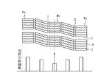
図4は、図2のIV−IV線に沿う断面図である。図5は、図1のトレッド踏面に構成したブロックのトレッド周方向断面図と、サイプ内に設けられた突起の個数を示した図である。 4 is a cross-sectional view taken along line IV-IV in FIG. FIG. 5 is a cross-sectional view in the tread circumferential direction of the block configured on the tread surface of FIG. 1 and the number of protrusions provided in the sipe.
ブロック単体で見たときの好適例では、ブロック4の最も踏み込み側に位置する踏み込み側サイプ5a内および、最も蹴り出し側に位置する蹴り出し側サイプ5b内の突起7の個数を、ブロック4の中間部に位置するサイプ内の突起7の個数より多く設ける。
In a preferred example when viewed as a single block, the number of
各ブロック4では、ブロック4の中間部付近の各ブロック分割部分8は、そこへの外力の作用に際し、隣接して存在するブロック分割部分8等による支持によって、倒れ込み量が必然的に少なくなるも、最も踏み込み側および、最も蹴り出し側に存在するブロック分割部分8は、隣接部に支え合うブロック分割部分8が全くもしくはほとんど存在しないため、ブロック4に大きな力が作用するとブロック分割部分8の倒れ込み量が多くなって、接地面積が低下するおそれがある。
これがためここでは、ブロック4の、踏み込み側サイプ5aおよび、蹴り出し側サイプ5bの少なくとも一方のサイプ内、図では双方のサイプ内の突起7の個数を、ブロック4の中間部に位置するサイプ内の突起7の個数より多くすることにより、特に撓み変形に対する、ブロック4の最も踏み込み側および最も蹴り出し側に存在するブロック分割部分8の支え合う力、すなわち、倒れ込み拘束力を強化することができる。これにより、接地面積の減少が有効に防止されることになって、氷雪路での、駆動性能および制動性能が向上し、一般路での操縦安定性も向上されることになる。
In each
For this reason, in this case, the number of
この場合、好ましくは、ブロック4の、中間部から、踏み込み側および蹴り出し側へ、サイプ内の突起7の個数を徐々に増加させることにより、ブロック端の倒れ込みを防止しつつ、ブロック中央の除水機能は確保する効果を得ることができる。その結果、接地面積が増加され、氷雪路での、駆動性能および制動性能が向上し、一般路での操縦安定性も向上されることになる。
ところで、図5に示すところでは、また、ブロック4の、踏み込み側サイプ5a内および蹴り出し側サイプ5b内のそれぞれに設けた突起7の数をともに同数としているが、それらの突起7の個数は相互に相違させることも可能である。
In this case, preferably, the number of
By the way, as shown in FIG. 5, the number of
ブロック4の、踏み込み側サイプ5aおよび、蹴り出し側サイプ5bの少なくとも一方のサイプ内の突起7の個数に対する、ブロック4の中間部に位置するサイプ内の突起7の個数の比が、1:0.2〜1:1とし、特に1:0.5とすることで、踏み込み側サイプ5aおよび、蹴り出し側サイプ5bのブロック分割部分8の倒れ込みを抑制するとともに、除水機能を確保する傾向がある。
The ratio of the number of
そして、ブロック4の、踏み込み側サイプ5aおよび、蹴り出し側サイプ5bの少なくとも一方のサイプ5内の突起7の総断面積を、ブロック4の中間部に位置するサイプ内の突起7の総断面積より多くすることで、踏み込み側サイプ5aおよび、蹴り出し側サイプ5bのブロック分割部分8の倒れ込みを抑制するとともに、除水機能を確保する傾向がある。
The total cross-sectional area of the
好ましくは、ブロック4の、中間部から、踏み込み側サイプ5aおよび蹴り出し側サイプ5bへ、サイプ内の突起7の総断面積を徐々に増加させることにより、ブロック端の倒れ込みを防止しつつ、ブロック中央の除水機能を確保する効果を得ることができる。その結果、接地面積が増加し、氷雪路での、駆動性能および制動性能が向上し、一般路での操縦安定性も向上されることになる。
また、ブロック4の、踏み込み側サイプ5a内と蹴り出し側サイプ5b内にそれぞれに設けた突起7の総断面積は、同一でも相違していても良い。
Preferably, the
Further, the total cross-sectional areas of the
特に、ブロック4の、踏み込み側サイプ5aおよび、蹴り出し側サイプ5bの少なくとも一方のサイプ内の突起7の総断面積に対する、ブロック4の中間部に位置するサイプ5内の突起7の総断面積の比率を、1:0.1〜1:1とし、特に好ましくは1:0.5とすることで、踏み込み側サイプ5aおよび、蹴り出し側サイプ5bのブロック分割部分8の倒れ込みを抑制するとともに、除水機能を確保する傾向がある。
In particular, the total cross-sectional area of the
ところで、図4に示すところでは、ブロック4に形成した四本のサイプ5の総てに突起7を設けているが、ブロック4に形成したサイプ5のうち、一部のもののみに突起7を設けることも可能である。
In the meantime, as shown in FIG. 4, the
図6は、図1に示すトレッドパターンの五列のブロック列のそれぞれを示す展開平面図および、それらのそれぞれのブロックに設けたサイプ内の突起の総個数を示した図である。 FIG. 6 is a developed plan view showing each of the five block rows of the tread pattern shown in FIG. 1, and a diagram showing the total number of protrusions in the sipe provided in each of those blocks.
トレッドパターン全体で見たときの好適例では、トレッドの最外側に位置する少なくとも一方側の側部域ブロック、図では両側の側部域ブロック4aの、それぞれのサイプ5内の突起7の総個数を、トレッド中央域のブロックである中央域ブロック4bのそれぞれのサイプ5内の突起7の総個数より多く設けることが好ましい。
In a preferred example when viewed in the entire tread pattern, the total number of
さらにまた、トレッドパターンにおいて、側部域ブロック4aは主に制動性能やコーナーリング性、中央域ブロック4bは主に制動性能および駆動性能に影響する。
そこで、複数本の周溝2と、複数本の横溝3とで区画される複数のブロック列中のそれぞれのブロック4のうち、トレッドの最外側に位置する側部域ブロック4aの少なくとも一方側のブロック、図では両側の側部域ブロック4aの、サイプ5内の突起7の総個数を、中央域ブロック4bの、サイプ5内の突起7の総個数より多くすることで、特に撓み変形における、ブロック分割部分8の倒れ込み変形を抑制することによって接地面積の低下を防止することができる。その結果、側部域ブロック4aのブロック分割部分8を突起7による支え合うことにより剛性を確保し、氷雪路の制動性能および一般路での操縦安定性を向上することができる。
一方、中央域ブロック4bに設けられたサイプ5には突起7の総個数を少なくすることで、突起7による支え合いが少なくなり、ブロック分割部分8が適度の撓み変形が実現されることになるので、サイプエッジのエッジ効果の一層の増加がもたらされることになり、氷雪路での制動性能、加速性能を向上させることができる。
したがって、このパターン内で突起7の総個数の適正な分布変化により、制動性能、加速性能および操縦安定性の各性能を同時に向上させることができる。
Furthermore, in the tread pattern, the
Therefore, at least one side of the
On the other hand, by reducing the total number of the
Therefore, by appropriately changing the distribution of the total number of the
好ましくは、中央域ブロック4bから、側部域ブロック4aへ、ブロック4に設けられたサイプ5内の突起7の総個数を徐々に増加させることで、中央域ブロック4bに近づくにつれて突起7の個数が少なくなり、エッヂ効果が上昇することができる。その結果、氷雪路での、駆動性能および制動性能が向上する。一方、側部域ブロック4aに近づくにつれて突起7の個数が多くなり、剛性を確保することができる。その結果、一般路での操縦安定性も向上されることになる。
また、図6に示すところでは、それぞれの、側部域ブロック4aに設けたそれぞれの突起7の総個数は、同数としているが、それらの突起7の個数は相互に相違させることも可能である。
Preferably, the total number of
Further, in FIG. 6, the total number of the
少なくとも一方の側部域ブロック4aの、サイプ5内の突起7の総個数に対する、中央域ブロック4bの、サイプ5内の突起7の総個数の比を、1:0.2〜1:1とし、特に好ましくは1:0.25とすることで、加速時に主に用いるセンター部のエッジ効果とともに、コーナーリング時のショルダー部の剛性を確保することができる傾向がある。
The ratio of the total number of
そして、少なくとも一方の側部域ブロック4aの、サイプ5内の突起7の総断面積を、中央域ブロック4bの、サイプ5内の突起7の総断面積より大きくすることで、主に加速時に用いるセンター部のエッジ効果とともに、コーナーリング時のショルダー部の剛性を確保することができる傾向がある。
好ましくは、中央域ブロック4bから、側部域ブロック4aへ、ブロック4に設けられたサイプ5内の突起7の断面積を徐々に増加させることで、中央域ブロック4bに近づくにつれて、突起7の断面積が少なくなり、エッヂ効果が上昇することができる。その結果、氷雪路での、駆動性能および制動性能が向上する。一方、側部域ブロック4aに近づくにつれて、突起の断面積が多くなり、剛性を確保することができる。その結果、一般路での操縦安定性も向上されることになる。
また、ブロック4の、側部域ブロック4aのそれぞれに設けた突起7の断面積は、同一でも相違していても良い。
And by making the total cross-sectional area of the
Preferably, by gradually increasing the cross-sectional area of the
Moreover, the cross-sectional area of the
特に、少なくとも一方の側部域ブロック4aの、サイプ5内の突起7の総断面積に対する、中央域ブロック4bの、サイプ5内の突起7の総断面積の比を、1:0.1〜1:1とし、特に好ましくは、1:0.25とすることで、主に加速時に用いるセンター部のエッジ効果とともに、コーナーリング時のショルダー部の剛性を確保することができる傾向がある。
In particular, the ratio of the total cross-sectional area of the
ところで、本発明に係る空気入りラジアルタイヤでは、ブロック4の表面に開口するサイプ5の延在形状は、ジグザグ状のみならず、直線状、クランク状、その他の所要形状とすることができ、サイプ5の一端又は両端がブロック4内に終了することもできる。また、そのサイプ5の形成態様は、二次元形態を有するものまたは三次元形態を有するものとすることができる。
したがって、図では、サイプ5を三次元サイプとしているも、それを二次元サイプとすることも可能である。
By the way, in the pneumatic radial tire according to the present invention, the extending shape of the
Therefore, in the figure, the
図7は、加硫モールドに装着されて、サイプ5およびサイプ5内の突起7を形成するのに用いることができるブレードを例示する断面斜視図であり、図8は、図7に示すブレードの正面図である。
FIG. 7 is a cross-sectional perspective view illustrating a blade that can be attached to a vulcanization mold and used to form the
本発明でいう、突起7を設けたサイプ5は、加硫モールドを持って生タイヤを加硫成型するに当って、ブレード11のスリットは、内に入り込んだゴム部分によって、各突起7が形成されることになり、ブレード11それ自身によるゴムの押し退けによってサイプ5が形成されることになる。
In the present invention, the
次に、図1、図9および図10に示すような構造を有する、サイズが195/65R15、56ピッチのサイズのラジアルタイヤを試作し、それぞれの諸元を変化させた実施例タイヤ1〜実施例タイヤ3、比較例タイヤ1とのそれぞれにつき、氷雪路での加速性能を測定した。
ここでは四本の周溝の寸法を、幅5mm、深さ9mm、横溝の寸法を幅5mm、深さ9mmとした。トレッド周方向に五列で区画されたブロック列の、各ブロックに、幅30mm、深さ7mmの三次元サイプを四本形成し、各サイプには、幅0.5mm、サイプ深さの56%の突起を設けた。
パターン全体としての突起の配置個数は同じ数となるように設置した。
ところで、本発明では、トレッド踏面以外のタイヤ構造については改変を要しないため、従来のラジアルタイヤの構造とほぼ同様とした。
Next, radial tires having a structure as shown in FIGS. 1, 9, and 10 and having a size of 195 / 65R15 and 56 pitches were manufactured as prototypes, and various tire specifications were changed. The acceleration performance on an icy and snowy road was measured for each of
Here, the dimensions of the four circumferential grooves are 5 mm wide and 9 mm deep, and the lateral grooves are 5 mm wide and 9 mm deep. Four three-dimensional sipes with a width of 30 mm and a depth of 7 mm are formed in each block of the block row divided into five rows in the tread circumferential direction, and each sipe has a width of 0.5 mm and 56% of the sipe depth. Protrusions were provided.
The number of protrusions arranged as a whole pattern was set to be the same number.
By the way, in the present invention, since the tire structure other than the tread surface is not required to be modified, it is almost the same as the structure of the conventional radial tire.
実施例タイヤ1では、全てのサイプに突起を均一に分布させて配置し、1本のサイプ内に7mmの間隔で三箇所の突起を設けた。実施例タイヤ2では、各ブロックの踏み込み側のおよび蹴り出し側のそれぞれのサイプ内に、5mmの間隔で四箇所に、中間部のサイプ内には10mmの間隔で二箇所に突起を配置した。実施例タイヤ3では、トレッドパターン内の、トレッド中央域に含まれるブロックに一箇所の突起,それに隣接するブロックに7mmの間隔で三箇所、両トレッド側部域のブロックに5mmの間隔で四箇所に、それぞれ突起を配置した。比較例タイヤ1は、サイプに突起を設けないものである。
In Example Tire 1, protrusions were uniformly distributed on all sipes, and three protrusions were provided in one sipe at intervals of 7 mm. In the
(加速性能)
実施例タイヤ1〜実施例タイヤ3、比較例タイヤ1のそれぞれにつき、タイヤを6JJのリムに組み付けて、内圧を200kPaとし、FR車で、ドライバー+60kgの荷重条件で、氷路上にてタイヤが空転しない限界のアクセル状態を保持して、5→150km/hまでの加速時間を計測した。
その結果を、表1に指数で示す。比較例タイヤ1の結果を100とし、指数が大きいほど、性能が良好なことを示す。
(Acceleration performance)
For each of Example tire 1 to
The results are shown in Table 1 as an index. The result of Comparative Example Tire 1 is set to 100, and the larger the index, the better the performance.

表1の結果から、実施例タイヤ1〜実施例タイヤ3は、比較例タイヤ1に対し、サイプ内に突起を設けることにより、氷上加速性能は良好となる。さらに、トレッド中央域のブロックの、サイプ内の突起の個数を、両トレッド側部域のブロックの、サイプ内の突起の個数より少なくすることで、エッヂ効果が良好となる。
From the results in Table 1, the example tire 1 to the
(制動性能)
実施例タイヤ1〜実施例タイヤ3、比較例タイヤ1のそれぞれにつき、氷路上で、20→0km/hでタイヤを完全にロックしたフルブレーキ時の制動距離で計測した。
その結果を、表2に指数で示す。比較例を100とし、指数が大きいほど、性能が良好なことを示す。
(Brake performance)
Each of Example Tire 1 to
The results are shown in Table 2 as an index. The comparative example is 100, and the larger the index, the better the performance.
表2の結果から、実施例タイヤ1〜実施例タイヤ3は、比較例タイヤ1に対し、サイプ内に突起を設けることにより、氷上制動性能が良好となる。実施例タイヤ2は、ブロックの、最も踏み込み側および、最も蹴り出し側に位置するサイプ内の突起の個数を、ブロックの中間部に位置するサイプ内の突起の個数より多くすることにより、トレッド部の接地面積の減少が少なく、制動性能が良好である。
From the results in Table 2, the example tire 1 to the
(コーナーリング性)
実施例タイヤ1〜実施例タイヤ3、比較例タイヤ1のそれぞれにつき、一般路面上で、コーナーリング時の車両の動きの正確性と、反応速度について10点満点で評価した。
その結果を表3に示し、数値が大きいほど、性能が良好なことを示す。
Each of Example Tire 1 to
The results are shown in Table 3. The larger the value, the better the performance.
表3の結果から、実施例タイヤ1〜実施例タイヤ3は、比較例タイヤ1に対し、サイプ内の突起がブロックを補強し、一般路コーナーリング性は良好となる。実施例タイヤ3は両トレッド側部域のブロックの剛性が最も強くなり、良好である。
From the results of Table 3, in the example tire 1 to the
表1〜表3の結果から、実施例タイヤ1〜実施例タイヤ3は、比較例タイヤ1に対し、サイプ内に突起を設けることで、氷上加速性能、氷上制動性能および一般路コーナーリング性が良好である。
また、サイプ内の突起の配置を変えることにより、コーナーリング性能重視のタイヤにも氷路制動性能重視のタイヤにも対応できる。
From the results of Tables 1 to 3, Example Tire 1 to
In addition, by changing the arrangement of the protrusions in the sipe, it is possible to deal with both tires that emphasize cornering performance and tires that emphasize ice braking performance.
1 トレッド踏面
2 周溝
3 横溝
4 ブロック
4a 側部域ブロック
4b 中央域ブロック
5 サイプ
5a 踏み込み側サイプ
5b 蹴り出し側サイプ
6 ブロック列
7 突起
8 ブロック分割部分
11 ブレード
12 スリット
DESCRIPTION OF SYMBOLS 1
Claims (10)
サイプの底部に、サイプの対向溝壁を一体的に連結する、少なくとも一個の上向き突起を設けることを特徴とする空気入りラジアルタイヤ。 A block is defined by arranging a plurality of circumferential grooves extending in the tread circumferential direction and a plurality of lateral grooves extending in the tread width direction so as to intersect these circumferential grooves on the tread tread surface. In a pneumatic radial tire provided with a plurality of sipes extending in the tread width direction,
A pneumatic radial tire characterized in that at least one upward protrusion is provided at the bottom of the sipe to integrally connect the opposing groove walls of the sipe.
Priority Applications (5)
| Application Number | Priority Date | Filing Date | Title |
|---|---|---|---|
| JP2007177502A JP2009012648A (en) | 2007-07-05 | 2007-07-05 | Pneumatic radial tire |
| PCT/JP2008/061897 WO2009005056A1 (en) | 2007-07-05 | 2008-07-01 | Radial pneumatic tire |
| CN2008801040189A CN101784401B (en) | 2007-07-05 | 2008-07-01 | Radial pneumatic tire |
| US12/667,572 US9409446B2 (en) | 2007-07-05 | 2008-07-01 | Pneumatic radial tire with tread having blocks having waved sipes |
| EP08777748.8A EP2177376B1 (en) | 2007-07-05 | 2008-07-01 | Radial pneumatic tire |
Applications Claiming Priority (1)
| Application Number | Priority Date | Filing Date | Title |
|---|---|---|---|
| JP2007177502A JP2009012648A (en) | 2007-07-05 | 2007-07-05 | Pneumatic radial tire |
Publications (1)
| Publication Number | Publication Date |
|---|---|
| JP2009012648A true JP2009012648A (en) | 2009-01-22 |
Family
ID=40226101
Family Applications (1)
| Application Number | Title | Priority Date | Filing Date |
|---|---|---|---|
| JP2007177502A Pending JP2009012648A (en) | 2007-07-05 | 2007-07-05 | Pneumatic radial tire |
Country Status (5)
| Country | Link |
|---|---|
| US (1) | US9409446B2 (en) |
| EP (1) | EP2177376B1 (en) |
| JP (1) | JP2009012648A (en) |
| CN (1) | CN101784401B (en) |
| WO (1) | WO2009005056A1 (en) |
Cited By (7)
| Publication number | Priority date | Publication date | Assignee | Title |
|---|---|---|---|---|
| JP2010188922A (en) * | 2009-02-19 | 2010-09-02 | Toyo Tire & Rubber Co Ltd | Pneumatic tire |
| JP2010254154A (en) * | 2009-04-24 | 2010-11-11 | Bridgestone Corp | Tire |
| JP2012532058A (en) * | 2009-06-29 | 2012-12-13 | ミシュラン ルシェルシュ エ テクニーク ソシエテ アノニム | Methods and configurations for improved snow static friction, highway wear, and off-road performance |
| WO2013183685A1 (en) | 2012-06-05 | 2013-12-12 | 横浜ゴム株式会社 | Pneumatic tire |
| JP2014514201A (en) * | 2011-03-21 | 2014-06-19 | ピレリ・タイヤ・ソチエタ・ペル・アツィオーニ | tire |
| CN106457920A (en) * | 2014-06-24 | 2017-02-22 | 米其林企业总公司 | Incised tread for civil engineering tire |
| KR20200121932A (en) * | 2019-04-16 | 2020-10-27 | 한국타이어앤테크놀로지 주식회사 | Tread block for heavy duty tire |
Families Citing this family (9)
| Publication number | Priority date | Publication date | Assignee | Title |
|---|---|---|---|---|
| CN104105604B (en) * | 2012-02-01 | 2016-09-14 | 株式会社普利司通 | Pneumatic tire |
| NL2009980C2 (en) * | 2012-12-13 | 2014-06-16 | Ct Voor Tech Informatica B V | A method of producing glass products from glass product material and an assembly for performing said method. |
| JP6086836B2 (en) * | 2013-07-25 | 2017-03-01 | 株式会社ブリヂストン | Pneumatic tire |
| EP3086959A4 (en) | 2013-12-26 | 2017-08-16 | Bridgestone Americas Tire Operations, LLC | Tire tread having a flexible gate apparatus |
| JP6329010B2 (en) * | 2014-06-13 | 2018-05-23 | 株式会社ブリヂストン | Pneumatic tire |
| JP6699245B2 (en) * | 2016-03-04 | 2020-05-27 | 住友ゴム工業株式会社 | Pneumatic tire |
| JP7225490B2 (en) | 2019-02-15 | 2023-02-21 | Toyo Tire株式会社 | pneumatic tire |
| JP6888706B1 (en) * | 2020-03-04 | 2021-06-16 | 横浜ゴム株式会社 | tire |
| JP2021138313A (en) | 2020-03-06 | 2021-09-16 | 住友ゴム工業株式会社 | tire |
Citations (7)
| Publication number | Priority date | Publication date | Assignee | Title |
|---|---|---|---|---|
| JPH0392403A (en) * | 1989-09-04 | 1991-04-17 | Bridgestone Corp | Pneumatic tire having block pattern with sipe |
| JPH10309910A (en) * | 1997-05-08 | 1998-11-24 | Bridgestone Corp | Pneumatic tire |
| JP2001105808A (en) * | 1999-10-06 | 2001-04-17 | Sumitomo Rubber Ind Ltd | Pneumatic tire |
| JP2001163015A (en) * | 1999-12-07 | 2001-06-19 | Sumitomo Rubber Ind Ltd | Studless tire |
| JP2005067274A (en) * | 2003-08-20 | 2005-03-17 | Sumitomo Rubber Ind Ltd | Pneumatic tire |
| JP2005132236A (en) * | 2003-10-30 | 2005-05-26 | Sumitomo Rubber Ind Ltd | Pneumatic tire |
| JP2006193088A (en) * | 2005-01-14 | 2006-07-27 | Bridgestone Corp | Pneumatic tire |
Family Cites Families (14)
| Publication number | Priority date | Publication date | Assignee | Title |
|---|---|---|---|---|
| JPS63137003A (en) | 1986-11-29 | 1988-06-09 | Yokohama Rubber Co Ltd:The | Tire for snowy or icy road |
| JPH061442Y2 (en) | 1987-02-19 | 1994-01-12 | 株式会社ブリヂストン | Pneumatic radial tires |
| JPH0325007A (en) * | 1989-06-23 | 1991-02-01 | Toyo Tire & Rubber Co Ltd | Radial tire |
| JP2906067B2 (en) * | 1989-11-29 | 1999-06-14 | 横浜ゴム株式会社 | Pneumatic studless tire |
| JPH06219108A (en) * | 1993-01-22 | 1994-08-09 | Yokohama Rubber Co Ltd:The | Tire for show-and-ice-covered road |
| JP3079026B2 (en) * | 1995-11-15 | 2000-08-21 | 住友ゴム工業株式会社 | studless tire |
| JP3471503B2 (en) * | 1995-11-20 | 2003-12-02 | 横浜ゴム株式会社 | Pneumatic tire |
| JPH10151915A (en) * | 1996-11-21 | 1998-06-09 | Sumitomo Rubber Ind Ltd | Pneumatic tire |
| DE60017329T2 (en) | 1999-10-06 | 2005-12-01 | Sumitomo Rubber Industries Ltd., Kobe | Spikelose tires |
| JP3894743B2 (en) * | 2001-04-05 | 2007-03-22 | 横浜ゴム株式会社 | Pneumatic tire |
| JP4377649B2 (en) * | 2003-10-15 | 2009-12-02 | 住友ゴム工業株式会社 | Pneumatic tire |
| JP2006062468A (en) | 2004-08-25 | 2006-03-09 | Bridgestone Corp | Pneumatic tire |
| JP2007055285A (en) | 2005-08-22 | 2007-03-08 | Bridgestone Corp | Pneumatic tire and manufacturing method of pneumatic tire |
| JP4730952B2 (en) * | 2005-09-05 | 2011-07-20 | 東洋ゴム工業株式会社 | Pneumatic tire |
-
2007
- 2007-07-05 JP JP2007177502A patent/JP2009012648A/en active Pending
-
2008
- 2008-07-01 EP EP08777748.8A patent/EP2177376B1/en not_active Not-in-force
- 2008-07-01 CN CN2008801040189A patent/CN101784401B/en not_active Expired - Fee Related
- 2008-07-01 WO PCT/JP2008/061897 patent/WO2009005056A1/en active Application Filing
- 2008-07-01 US US12/667,572 patent/US9409446B2/en active Active
Patent Citations (7)
| Publication number | Priority date | Publication date | Assignee | Title |
|---|---|---|---|---|
| JPH0392403A (en) * | 1989-09-04 | 1991-04-17 | Bridgestone Corp | Pneumatic tire having block pattern with sipe |
| JPH10309910A (en) * | 1997-05-08 | 1998-11-24 | Bridgestone Corp | Pneumatic tire |
| JP2001105808A (en) * | 1999-10-06 | 2001-04-17 | Sumitomo Rubber Ind Ltd | Pneumatic tire |
| JP2001163015A (en) * | 1999-12-07 | 2001-06-19 | Sumitomo Rubber Ind Ltd | Studless tire |
| JP2005067274A (en) * | 2003-08-20 | 2005-03-17 | Sumitomo Rubber Ind Ltd | Pneumatic tire |
| JP2005132236A (en) * | 2003-10-30 | 2005-05-26 | Sumitomo Rubber Ind Ltd | Pneumatic tire |
| JP2006193088A (en) * | 2005-01-14 | 2006-07-27 | Bridgestone Corp | Pneumatic tire |
Cited By (9)
| Publication number | Priority date | Publication date | Assignee | Title |
|---|---|---|---|---|
| JP2010188922A (en) * | 2009-02-19 | 2010-09-02 | Toyo Tire & Rubber Co Ltd | Pneumatic tire |
| JP2010254154A (en) * | 2009-04-24 | 2010-11-11 | Bridgestone Corp | Tire |
| JP2012532058A (en) * | 2009-06-29 | 2012-12-13 | ミシュラン ルシェルシュ エ テクニーク ソシエテ アノニム | Methods and configurations for improved snow static friction, highway wear, and off-road performance |
| JP2014514201A (en) * | 2011-03-21 | 2014-06-19 | ピレリ・タイヤ・ソチエタ・ペル・アツィオーニ | tire |
| WO2013183685A1 (en) | 2012-06-05 | 2013-12-12 | 横浜ゴム株式会社 | Pneumatic tire |
| CN106457920A (en) * | 2014-06-24 | 2017-02-22 | 米其林企业总公司 | Incised tread for civil engineering tire |
| CN106457920B (en) * | 2014-06-24 | 2018-06-08 | 米其林企业总公司 | The tyre surface with narrow otch of civil engineering tire |
| KR20200121932A (en) * | 2019-04-16 | 2020-10-27 | 한국타이어앤테크놀로지 주식회사 | Tread block for heavy duty tire |
| KR102185593B1 (en) * | 2019-04-16 | 2020-12-03 | 한국타이어앤테크놀로지 주식회사 | Tread block for heavy duty tire |
Also Published As
| Publication number | Publication date |
|---|---|
| US9409446B2 (en) | 2016-08-09 |
| US20100212794A1 (en) | 2010-08-26 |
| EP2177376B1 (en) | 2013-06-12 |
| CN101784401B (en) | 2013-02-20 |
| CN101784401A (en) | 2010-07-21 |
| EP2177376A4 (en) | 2011-09-07 |
| WO2009005056A1 (en) | 2009-01-08 |
| EP2177376A1 (en) | 2010-04-21 |
Similar Documents
| Publication | Publication Date | Title |
|---|---|---|
| JP2009012648A (en) | Pneumatic radial tire | |
| JP4397956B1 (en) | Pneumatic tire | |
| JP4294532B2 (en) | Pneumatic tire | |
| JP4471033B1 (en) | Pneumatic tire | |
| JP4377649B2 (en) | Pneumatic tire | |
| JP5875814B2 (en) | Pneumatic tire | |
| JP5270417B2 (en) | Pneumatic tire | |
| JP5675580B2 (en) | Pneumatic tire | |
| JP4589680B2 (en) | Pneumatic tire | |
| EP3115229B1 (en) | Heavy duty pneumatic tire | |
| JP6194885B2 (en) | Pneumatic tire | |
| JP5560894B2 (en) | Pneumatic tire | |
| JP2008290521A (en) | Pneumatic tire | |
| JP5200123B2 (en) | Heavy duty pneumatic tire | |
| JP2010254155A (en) | Tire | |
| JP2006062469A (en) | Pneumatic tire | |
| WO2006049298A1 (en) | Pneumatic tire | |
| JP2008030656A (en) | Pneumatic tire | |
| JP2009018617A (en) | Pneumatic tire | |
| JP2007290628A (en) | Pneumatic tire | |
| JP2009298364A (en) | Pneumatic tire | |
| JP2006007796A (en) | Pneumatic tire | |
| JP5506463B2 (en) | Pneumatic tire | |
| JP5426287B2 (en) | Pneumatic tire | |
| WO2011111352A1 (en) | Pneumatic tire |
Legal Events
| Date | Code | Title | Description |
|---|---|---|---|
| A621 | Written request for application examination |
Free format text: JAPANESE INTERMEDIATE CODE: A621 Effective date: 20100630 |
|
| A131 | Notification of reasons for refusal |
Free format text: JAPANESE INTERMEDIATE CODE: A131 Effective date: 20120417 |
|
| A521 | Written amendment |
Free format text: JAPANESE INTERMEDIATE CODE: A523 Effective date: 20120615 |
|
| A02 | Decision of refusal |
Free format text: JAPANESE INTERMEDIATE CODE: A02 Effective date: 20120703 |