WO2015012041A1 - 全酸化性物質濃度の測定方法、基板洗浄方法および基板洗浄システム - Google Patents
全酸化性物質濃度の測定方法、基板洗浄方法および基板洗浄システム Download PDFInfo
- Publication number
- WO2015012041A1 WO2015012041A1 PCT/JP2014/066522 JP2014066522W WO2015012041A1 WO 2015012041 A1 WO2015012041 A1 WO 2015012041A1 JP 2014066522 W JP2014066522 W JP 2014066522W WO 2015012041 A1 WO2015012041 A1 WO 2015012041A1
- Authority
- WO
- WIPO (PCT)
- Prior art keywords
- sulfuric acid
- concentration
- solution
- electrolytic
- measuring
- Prior art date
- Legal status (The legal status is an assumption and is not a legal conclusion. Google has not performed a legal analysis and makes no representation as to the accuracy of the status listed.)
- Ceased
Links
Images


Classifications
-
- H—ELECTRICITY
- H10—SEMICONDUCTOR DEVICES; ELECTRIC SOLID-STATE DEVICES NOT OTHERWISE PROVIDED FOR
- H10P—GENERIC PROCESSES OR APPARATUS FOR THE MANUFACTURE OR TREATMENT OF DEVICES COVERED BY CLASS H10
- H10P70/00—Cleaning of wafers, substrates or parts of devices
- H10P70/20—Cleaning during device manufacture
-
- B—PERFORMING OPERATIONS; TRANSPORTING
- B08—CLEANING
- B08B—CLEANING IN GENERAL; PREVENTION OF FOULING IN GENERAL
- B08B3/00—Cleaning by methods involving the use or presence of liquid or steam
- B08B3/04—Cleaning involving contact with liquid
-
- C—CHEMISTRY; METALLURGY
- C25—ELECTROLYTIC OR ELECTROPHORETIC PROCESSES; APPARATUS THEREFOR
- C25B—ELECTROLYTIC OR ELECTROPHORETIC PROCESSES FOR THE PRODUCTION OF COMPOUNDS OR NON-METALS; APPARATUS THEREFOR
- C25B1/00—Electrolytic production of inorganic compounds or non-metals
- C25B1/01—Products
- C25B1/28—Per-compounds
- C25B1/30—Peroxides
-
- C—CHEMISTRY; METALLURGY
- C25—ELECTROLYTIC OR ELECTROPHORETIC PROCESSES; APPARATUS THEREFOR
- C25B—ELECTROLYTIC OR ELECTROPHORETIC PROCESSES FOR THE PRODUCTION OF COMPOUNDS OR NON-METALS; APPARATUS THEREFOR
- C25B15/00—Operating or servicing cells
- C25B15/02—Process control or regulation
-
- C—CHEMISTRY; METALLURGY
- C25—ELECTROLYTIC OR ELECTROPHORETIC PROCESSES; APPARATUS THEREFOR
- C25B—ELECTROLYTIC OR ELECTROPHORETIC PROCESSES FOR THE PRODUCTION OF COMPOUNDS OR NON-METALS; APPARATUS THEREFOR
- C25B15/00—Operating or servicing cells
- C25B15/08—Supplying or removing reactants or electrolytes; Regeneration of electrolytes
-
- C—CHEMISTRY; METALLURGY
- C25—ELECTROLYTIC OR ELECTROPHORETIC PROCESSES; APPARATUS THEREFOR
- C25B—ELECTROLYTIC OR ELECTROPHORETIC PROCESSES FOR THE PRODUCTION OF COMPOUNDS OR NON-METALS; APPARATUS THEREFOR
- C25B9/00—Cells or assemblies of cells; Constructional parts of cells; Assemblies of constructional parts, e.g. electrode-diaphragm assemblies; Process-related cell features
-
- G—PHYSICS
- G01—MEASURING; TESTING
- G01N—INVESTIGATING OR ANALYSING MATERIALS BY DETERMINING THEIR CHEMICAL OR PHYSICAL PROPERTIES
- G01N21/00—Investigating or analysing materials by the use of optical means, i.e. using sub-millimetre waves, infrared, visible or ultraviolet light
- G01N21/17—Systems in which incident light is modified in accordance with the properties of the material investigated
- G01N21/25—Colour; Spectral properties, i.e. comparison of effect of material on the light at two or more different wavelengths or wavelength bands
- G01N21/255—Details, e.g. use of specially adapted sources, lighting or optical systems
-
- G—PHYSICS
- G01—MEASURING; TESTING
- G01N—INVESTIGATING OR ANALYSING MATERIALS BY DETERMINING THEIR CHEMICAL OR PHYSICAL PROPERTIES
- G01N21/00—Investigating or analysing materials by the use of optical means, i.e. using sub-millimetre waves, infrared, visible or ultraviolet light
- G01N21/17—Systems in which incident light is modified in accordance with the properties of the material investigated
- G01N21/25—Colour; Spectral properties, i.e. comparison of effect of material on the light at two or more different wavelengths or wavelength bands
- G01N21/27—Colour; Spectral properties, i.e. comparison of effect of material on the light at two or more different wavelengths or wavelength bands using photo-electric detection ; circuits for computing concentration
- G01N21/274—Calibration, base line adjustment, drift correction
-
- G—PHYSICS
- G01—MEASURING; TESTING
- G01N—INVESTIGATING OR ANALYSING MATERIALS BY DETERMINING THEIR CHEMICAL OR PHYSICAL PROPERTIES
- G01N21/00—Investigating or analysing materials by the use of optical means, i.e. using sub-millimetre waves, infrared, visible or ultraviolet light
- G01N21/17—Systems in which incident light is modified in accordance with the properties of the material investigated
- G01N21/25—Colour; Spectral properties, i.e. comparison of effect of material on the light at two or more different wavelengths or wavelength bands
- G01N21/31—Investigating relative effect of material at wavelengths characteristic of specific elements or molecules, e.g. atomic absorption spectrometry
- G01N21/33—Investigating relative effect of material at wavelengths characteristic of specific elements or molecules, e.g. atomic absorption spectrometry using ultraviolet light
-
- H—ELECTRICITY
- H10—SEMICONDUCTOR DEVICES; ELECTRIC SOLID-STATE DEVICES NOT OTHERWISE PROVIDED FOR
- H10P—GENERIC PROCESSES OR APPARATUS FOR THE MANUFACTURE OR TREATMENT OF DEVICES COVERED BY CLASS H10
- H10P72/00—Handling or holding of wafers, substrates or devices during manufacture or treatment thereof
- H10P72/04—Apparatus for manufacture or treatment
- H10P72/0402—Apparatus for fluid treatment
-
- H—ELECTRICITY
- H10—SEMICONDUCTOR DEVICES; ELECTRIC SOLID-STATE DEVICES NOT OTHERWISE PROVIDED FOR
- H10P—GENERIC PROCESSES OR APPARATUS FOR THE MANUFACTURE OR TREATMENT OF DEVICES COVERED BY CLASS H10
- H10P72/00—Handling or holding of wafers, substrates or devices during manufacture or treatment thereof
- H10P72/04—Apparatus for manufacture or treatment
- H10P72/0402—Apparatus for fluid treatment
- H10P72/0406—Apparatus for fluid treatment for cleaning followed by drying, rinsing, stripping, blasting or the like
- H10P72/0411—Apparatus for fluid treatment for cleaning followed by drying, rinsing, stripping, blasting or the like for wet cleaning or washing
-
- H—ELECTRICITY
- H10—SEMICONDUCTOR DEVICES; ELECTRIC SOLID-STATE DEVICES NOT OTHERWISE PROVIDED FOR
- H10P—GENERIC PROCESSES OR APPARATUS FOR THE MANUFACTURE OR TREATMENT OF DEVICES COVERED BY CLASS H10
- H10P72/00—Handling or holding of wafers, substrates or devices during manufacture or treatment thereof
- H10P72/06—Apparatus for monitoring, sorting, marking, testing or measuring
- H10P72/0604—Process monitoring, e.g. flow or thickness monitoring
-
- H—ELECTRICITY
- H10—SEMICONDUCTOR DEVICES; ELECTRIC SOLID-STATE DEVICES NOT OTHERWISE PROVIDED FOR
- H10P—GENERIC PROCESSES OR APPARATUS FOR THE MANUFACTURE OR TREATMENT OF DEVICES COVERED BY CLASS H10
- H10P74/00—Testing or measuring during manufacture or treatment of wafers, substrates or devices
- H10P74/20—Testing or measuring during manufacture or treatment of wafers, substrates or devices characterised by the properties tested or measured, e.g. structural or electrical properties
-
- G—PHYSICS
- G01—MEASURING; TESTING
- G01N—INVESTIGATING OR ANALYSING MATERIALS BY DETERMINING THEIR CHEMICAL OR PHYSICAL PROPERTIES
- G01N2201/00—Features of devices classified in G01N21/00
- G01N2201/12—Circuits of general importance; Signal processing
- G01N2201/127—Calibration; base line adjustment; drift compensation
Definitions
- the present invention relates to a measurement method, a substrate cleaning method, and a substrate cleaning system for quantifying an electrolytic sulfuric acid oxidizing agent obtained by electrolyzing sulfuric acid.
- the concentration of sulfuric acid in the chemical solution greatly affects the cleaning effect.
- a method for measuring the oxidant concentration in the electrolytic sulfuric acid solution there is a measurement method by titration analysis using an oxidation-reduction reaction as disclosed in Patent Document 3.
- this is a method that can easily measure the oxidant concentration in electrolytic sulfuric acid, it takes time to dispense the liquid to be measured and performs titration, and the post-measurement liquid must be collected because it contains a titration reagent. This is so-called off-line measurement.
- a densitometer for measuring the total concentration of oxidizing substances for example, there is Patent Document 4.
- it is necessary to heat-treat the measurement liquid in advance it takes time to measure, and there is a problem that the concentration meter has a complicated apparatus configuration.
- An object of the present invention is to provide a total oxidizing substance concentration measuring method, a substrate cleaning method, and a substrate cleaning system capable of measuring the total oxidizing substance of electrolytic sulfuric acid in a short time and enabling online monitoring.
- the first present invention is a method for measuring the total oxidizing substance concentration of electrolytic sulfuric acid, Using the absorbance data obtained by correcting the baseline by associating the sulfuric acid preparation solution having the same sulfuric acid concentration as that of the electrolytic sulfuric acid with the total oxidizing substance concentration as a standard sample solution, The concentration of the total oxidizing substance in the electrolytic sulfuric acid based on the data was measured by measuring the absorbance at a wavelength of 190 to 290 nm using an electrolytic sulfuric acid having a sulfuric acid concentration of 60 to 97 mass% and a liquid temperature of 20 to 70 ° C. as a sample liquid. Is measured.
- the total oxidizing substance concentration measuring method is characterized in that, in the first aspect of the invention, the total oxidizing substance includes peroxomonosulfuric acid, peroxodisulfuric acid, and hydrogen peroxide.
- a substrate cleaning method is a substrate cleaning method in which a sulfuric acid solution is circulated while electrolyzing to increase an electrolytic concentration, and a semiconductor substrate is cleaned using an electrolytic sulfuric acid solution having an increased electrolytic concentration, The electrolytic sulfuric acid is measured by the measuring method of the first or second invention, and the total oxidizing substance concentration of the electrolytic sulfuric acid solution is monitored on-line.
- the substrate cleaning method according to a fourth aspect of the present invention is the method according to the third aspect of the present invention, wherein before the electrolytic sulfuric acid comes into contact with the substrate, a part is branched from the system as a sample solution, and the absorbance measurement is performed. The sample liquid is returned to the system.
- the cleaning waste solution used for substrate cleaning is discarded without being recycled and the electrolytic sulfuric acid solution is removed from the line through which the electrolytic solution is circulated.
- a part of the electrolytic sulfuric acid is branched as a sample solution, and the absorbance is measured to measure the total oxidizing substance concentration. After the measurement, the sample solution is measured at a position before substrate cleaning. Is returned to the system.
- the substrate cleaning method of the sixth aspect of the present invention is characterized in that, in the fifth aspect of the present invention, the electrolyzed sulfuric acid after the measurement is returned upstream from the position branched from the supply line.
- a substrate cleaning system is an electrolysis apparatus for electrolyzing a sulfuric acid solution; A circulation line for circulating the sulfuric acid solution through the electrolysis apparatus while electrolyzing it; A substrate cleaning apparatus for cleaning a semiconductor substrate using electrolytic sulfuric acid; A supply line for sending electrolytic sulfuric acid to the substrate cleaning device; An absorptiometer, A storage unit for holding absorbance data that is baseline-corrected in association with the total oxidizing substance concentration using an electrolytic sulfuric acid preparation solution having the same sulfuric acid concentration as that of the electrolytic sulfuric acid as a standard sample solution; A branch line that takes electrolytic sulfuric acid from one of the electrolyzer, circulation line, and supply line and branches to the absorptiometer, Data obtained by measuring absorbance at a wavelength of 190 to 290 nm using the electrolytic sulfuric acid having a sulfuric acid concentration of 60 to 97% by mass and a liquid temperature of 20 to 70 ° C. as a sample solution, and the baseline correction And a measuring device
- the present invention it is possible to measure on-line the concentration of an oxidizing substance present in a cleaning liquid for removing and cleaning contaminants from an electronic material such as a substrate. Therefore, the performance of the cleaning apparatus can be managed by installing an online monitor or the like that applies the method of the present invention to the cleaning method or the cleaning system.
- oxidizing substances such as peroxodisulfuric acid, peroxomonosulfuric acid, and hydrogen peroxide are mixed.
- the calibration relationship between sulfuric acid concentration, liquid temperature, light absorption intensity, and total oxidizable substance concentration in advance for example, the manual titration method (potassium iodide aqueous solution was added to the solution containing the oxidative substance, Titration of iodine released by oxidation-reduction reaction with a known concentration of sodium thiosulfate solution as a titrant, and measuring the concentration of all oxidizing substances) and the spectrophotometric method.
- the calibration relationship derived from the relationship with the absorbance is not limited to the iodine titration method, and examples thereof include potentiometric measurement.
- the present invention by using absorbance data obtained by performing baseline correction corresponding to the total oxidizing substance concentration in advance using an electrolytic sulfuric acid preparation solution having the same sulfuric acid concentration as the electrolytic sulfuric acid concentration as a standard sample solution, a predetermined concentration, By measuring the absorbance at a wavelength of 190 to 290 nm using electrolytic sulfuric acid at a specified temperature as the sample solution, the total oxidizing substance concentration in the electrolytic sulfuric acid can be measured in a short time, and online monitoring using the measurement results is possible. Become.
- the sample solution used for the measurement can be collected and reused as desired.
- the present invention is an analysis method for measuring an oxidizing agent present in an electrolytic sulfuric acid solution using a light absorbance in the ultraviolet region of 190 nm to 290 nm at a known concentration of sulfuric acid, and the oxidizing agent concentration without discharging the measuring solution.
- the present invention relates to a device for online monitoring. Note that the absorbance is preferably limited to a single spectrum.
- peroxodisulfuric acid When 60% by mass or more of sulfuric acid is electrolyzed, peroxodisulfuric acid is produced according to the following reaction formula (1). 2HSO 4 ⁇ ⁇ H 2 S 2 O 8 + 2e ⁇ (1) Further, peroxomonosulfuric acid is produced from peroxodisulfuric acid by the equilibrium reaction shown in the formula (2), and further hydrogen peroxide is produced by the equilibrium reaction shown in the formula (3). Therefore, in the sulfuric acid electrolyte solution, oxidizing substances such as peroxodisulfuric acid, peroxomonosulfuric acid, and hydrogen peroxide are mixed, but these can all be quantified by iodine titration method, etc. It is possible to grasp the total oxidizable substance concentration contained in this titration method.
- peroxodisulfuric acid and peroxomonosulfuric acid are collectively referred to as persulfuric acid.
- the iodine titration method is a method in which an aqueous potassium iodide solution is added to a solution containing an oxidizing substance, and the iodine released by the oxidation-reduction reaction with the oxidizing substance is titrated with a sodium thiosulfate solution having a known concentration as a titration solution.
- This is a method for measuring the concentration of an oxidizing substance.
- a titration reagent is added to the sampled solution and a titration operation is required. Therefore, it takes time to measure, and the solution after analysis needs to be discarded. Impossible.
- the concentration of the total oxidizable substance is measured by measuring the absorbance of the measurement liquid without pretreatment such as heating by measuring sulfuric acid of a known concentration or the concentration of sulfuric acid with another analyzer.
- Peroxydisulfuric acid, peroxomonosulfuric acid, and hydrogen peroxide which are oxidants, all show an absorption peak near 190 to 200 nm, but the molar extinction coefficient is different, so the total amount cannot be grasped when mixed. .
- these oxidants exist in an equilibrium relationship in electrolytic sulfuric acid, so that the predetermined sulfuric acid concentration, that is, the ratio of sulfuric acid and water, and from room temperature to about 70 ° C.
- the existence ratio of the mixed oxidizing substance is almost constant.
- peroxodisulfuric acid, peroxomonosulfuric acid, and hydrogen peroxide which are the main components among all oxidizing substances, account for 95% by mass or more immediately after electrolysis, and further occupy over time. The rate tends to increase.
- the iodometric titration method it is possible to obtain a high correlation with, for example, the iodometric titration method, by knowing the sulfuric acid concentration in advance and measuring the light absorption wavelength and the absorbance at 190 to 290 nm.
- fluororesin piping for the wetted parts of the device for measuring the absorbance and quartz for the absorbance measuring cell, it is possible to avoid contamination by impurities in the solution after measurement, and discard it if desired. Without using it, it can be used for its intended purpose.
- the method for measuring the sulfuric acid concentration is not particularly required in the present invention, and any method can be used as long as it can be measured online, such as a sound velocity measurement method or a resonance vibration method.
- a method of calculating the oxidant concentration from the sulfuric acid concentration and the absorption intensity of the measurement solution a method of measuring the relationship between the absorption intensity and the oxidant concentration at a predetermined sulfuric acid concentration in advance, and measuring the oxidant concentration only at the predetermined sulfuric acid concentration. Either is possible. By using this principle, online monitoring of the oxidant concentration in the electrolytic sulfuric acid apparatus is possible.
- the sample to be measured is put on the sample side, the wavelength is scanned, and the absorption spectrum of the sample is obtained by subtracting from the absorption curve (baseline) for the control sample.
- the absorbance can be measured using a sulfuric acid solution having a set sulfuric acid concentration as a baseline.
- an electrolytic device 2 that performs electrolysis while passing a sulfuric acid solution and a storage tank 3 that stores a sulfuric acid solution (including an electrolytic sulfuric acid solution after electrolysis) are connected by a circulation line 4.
- the electrolysis apparatus 2 is a diaphragm type, and an anode and a cathode are arranged inside without being separated by a diaphragm, and a DC power source (not shown) is connected to both electrodes.
- the anode and the cathode it is desirable that at least the portion in contact with the sulfuric acid solution is a diamond electrode.
- the electrolysis apparatus may be configured as a diaphragm type, and may be provided with a bipolar electrode, or the bipolar electrode may be configured with a diamond electrode.
- a liquid feed pump 5 and a cooler 6 are interposed in this order in the circulation line 4 on the feed side from the storage tank 3 to the electrolyzer 2.
- a gas-liquid separation tank 7 is interposed in the return-side circulation line 4 from the electrolyzer 2 to the storage tank 3.
- a pure water supply line 8 for introducing pure water into the storage tank 3 and a concentrated sulfuric acid supply line 9 for introducing concentrated sulfuric acid into the storage tank 3 are connected.
- pure water or concentrated sulfuric acid can be supplied to the storage tank 3 during operation. In supply during operation, the concentration of sulfuric acid in the storage tank can be adjusted.
- a supply line 10 provided with a persulfuric acid feed pump 11 is connected, and the front end side of the supply line 10 is connected to a single wafer cleaning device 20 via a heater 17. .
- a transient type can be suitably used.
- the solution in the storage tank 3 is preferably adjusted to 50 to 90 ° C.
- a filter 12 and a preheating tank 13 are connected to the supply line 10 between the persulfuric acid feed pump 11 and the heater 17 in this order.
- the filter 12 captures and removes particles contained in the persulfuric acid-containing sulfuric acid solution that is fed.
- the preheating tank 13 stores and heats the solution sent from the storage tank 3, and heats the solution to 90 to 120 ° C., for example.
- a branch line 14 for branching out a part of the electrolytic solution flowing through the supply line 10 is branched and connected, and the branch line 14 is oxidized.
- the agent concentration monitoring device 15 is connected.
- the solution introduced into the oxidant concentration monitoring device 15 is the supply line 10 between the preheating tank 13 and the heater 17 by the return line 16 and upstream of the branch position, or the preheating tank 13 or the supply line. 10 is configured to be sent to 10.
- the oxidant concentration monitoring device 15 corresponds to the measuring device of the present invention, and associates the absorptiometer 15a and an electrolytic sulfuric acid preparation solution having the same sulfuric acid concentration as the sulfuric acid concentration of the electrolytic sulfuric acid with the total oxidizing substance concentration as a standard sample solution.
- a nonvolatile storage unit 15b that holds the baseline-corrected absorbance data and a control unit 15c that controls the entire oxidant concentration monitoring device 15 are provided.
- As the storage unit 15b a flash memory, an HDD, a detachable USB memory, or the like can be used.
- the single wafer cleaning apparatus 20 sprays, drops, or flows the cleaning solution supplied from the supply line 10 onto the semiconductor substrate 100 installed in the single wafer cleaning apparatus 20. Note that the solution may be sprayed onto the semiconductor substrate 100 by applying pressure when dropping or flowing.
- a drain line 21 through which the solution in the apparatus is drained is connected, and the drain line 21 is branched into an extra-system drain line 22 and a recovery line 23.
- An unused solution recovery tank 24 is connected to the recovery line 23.
- drainage at the time of cleaning is connected to the drainage line 21 and the system drainage line 22 through valve operation or the like, and the drainage is drained out of the system through these.
- the unused cleaning liquid other than at the time of cleaning is recovered in the unused solution recovery tank 24 through the drain line 21 and the recovery line 23 connected by a valve operation or the like.
- a return line 25 is connected to the unused solution recovery tank 24, and the front side of the return line 25 is connected to the storage tank 3.
- the return line 25 is provided with a reflux liquid pump 26, a filter 27, and a cooler 28 in this order from the unused recovery tank 24 to the storage tank 3.
- the oxidant concentration monitoring device 15 stores in advance data relating to absorbance obtained by performing baseline correction in association with the total oxidizing substance concentration using an electrolytic sulfuric acid adjustment solution having the same sulfuric acid concentration as the electrolytic sulfuric acid introduced in the branch line 14 in advance as a standard sample solution. 15b.
- the sulfuric acid concentration is 60 to 97% by mass
- the liquid temperature is selected from the range of 20 to 70 ° C.
- the wavelength of 190 to 290 nm is selected in advance in the storage tank 3 is used.
- the solution temperature of the electrolytic sulfuric acid is measured by a thermometer provided in the preheating tank 13 (not shown), or measured by a thermometer provided in the oxidant concentration monitoring device 15 (not shown). You can get it.
- the amount of total oxidizable substances can be obtained by manual titration with iodine, and the relationship with absorbance can be obtained.
- an aqueous potassium iodide solution is added to a solution containing an oxidizing substance, and titrated with a sodium thiosulfate solution with a known concentration using the oxidizing substance and iodine liberated by the oxidation-reduction reaction as a titrant. Measure the concentration.
- the relationship between the sulfuric acid concentration, the absorbance at a wavelength of 190 nm to 290 nm, and the total oxidizable substance amount is acquired as data.
- a sulfuric acid solution having a sulfuric acid concentration of 60 to 97% by mass is stored in the storage tank 3.
- the sulfuric acid concentration can be adjusted by supplying a solution through the pure water supply line 8 and the concentrated sulfuric acid supply line 9.
- the sulfuric acid solution is fed through the circulation line 4 by the feed pump 5 and introduced into the liquid inlet side of the electrolysis apparatus 2.
- the sulfuric acid solution introduced into the electrolysis apparatus 2 is electrolyzed by energization between the anode and the cathode by a DC power source.
- an oxidizing substance containing persulfuric acid is generated on the anode side by the electrolysis.
- the oxidizing substance is returned to the storage tank 3 side through the circulation line 4 while being mixed with the sulfuric acid solution.
- gas generated by electrolysis is separated by the gas-liquid separator 7.
- the electrolyzed sulfuric acid solution becomes electrolytic sulfuric acid containing an oxidizing substance such as persulfuric acid, and is returned to the storage tank 3 through the circulation line 4 and then repeatedly sent to the electrolyzer 2.
- the sulfuric acid solution is sent to the electrolysis apparatus 2, it is cooled by the cooler 6 as necessary and introduced into the electrolysis apparatus 2 at a temperature of 30 to 70 ° C., for example.
- the electrolytic sulfuric acid in the storage tank 3 a part of the electrolytic sulfuric acid in the storage tank 3 is fed through the supply line 10 by the liquid feed pump 11 at an appropriate time.
- the electrolytic sulfuric acid flowing through the supply line 10 is captured and removed by the filter 12 and then introduced into the preheating tank 13 and heated to 90 to 120 ° C., for example.
- the electrolytic sulfuric acid in the preheating tank 13 is sent to the heater 17 through the supply line 10 and heated to, for example, 140 to 220 ° C.
- the electrolytic sulfuric acid is brought into contact with the semiconductor substrate 100 within one minute. Wash the formula.
- the cleaning liquid used for the cleaning contacts the semiconductor substrate 100 and is then discharged out of the system through the drainage line 21 and the external discharge line 22.
- the supply line 10 or a relay tank (not shown) interposed in the supply line 10 is used.
- a part of the electrolytic sulfuric acid is taken out and introduced into the oxidant concentration monitoring device 15 through the branch line 14.
- the oxidant concentration monitoring device 15 confirms that the introduced electrolytic sulfuric acid is in the range of 20 to 70 ° C., and the absorbance is measured by the absorptiometer 15a with a single spectrum having a wavelength of 190 to 290 nm. The corresponding total oxidizing substance concentration is obtained from the sulfuric acid concentration and the absorbance measurement result.
- the acquired total oxidizing substance concentration can be printed on a display unit or a printing unit (not shown). Adjusting the electrolysis conditions in the electrolysis apparatus 2, the liquid feed timing in the persulfuric acid feed pump 11, the liquid feed amount, the installation of the semiconductor substrate 100, and the like from the acquired total oxidizing substance concentration to make it suitable for cleaning Can do. Electrolysis conditions, liquid feeding timing, liquid feeding amount, installation of the semiconductor substrate 100, and the like can be controlled through the control unit 15c controlled according to the acquired total oxidizing substance concentration, and the acquired total oxidation. Depending on the concentration of the active substance, the electrolysis conditions, liquid feeding timing, liquid feeding amount, installation, etc. may be adjusted manually.
- the electrolytic sulfuric acid introduced into the oxidant concentration monitoring device 15 can be returned to the preheating tank 13 by the return line 16 and reused.
- the electrolytic sulfuric acid introduced into the oxidant concentration monitoring device 15 is returned to the supply line 10 between the preheating tank 13 and the heater 17 and upstream of the branch position, and reused. You may make it do.
- the position for returning the electrolytic sulfuric acid used for the measurement of the oxidant concentration is not limited to a specific position, but it is desirable to return it to the upstream side from the measurement point. Thereby, the influence on the system can be reduced and the electrolytic sulfuric acid used for the measurement can be reused.
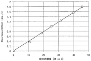
- Example 1 Sulfuric acid electrolytes containing oxidants with different concentrations were electrolyzed with sulfuric acid adjusted to 80% by mass, and the absorbance at 200 to 300 nm was measured with 80% by mass sulfuric acid as the baseline. The oxidant concentration was analyzed by iodometric titration. Electrolysis is an electrolytic sulfuric acid solution in which conductive diamond electrodes are used for the anode and the cathode and the input current amount is 0, 5, 10, 15 [Ah / L]. The spectrum in each electrolytic sulfuric acid solution is shown in FIG. Thus, the higher the oxidant concentration, the higher the absorption intensity in the region of 200 to 300 nm.
- FIG. 4 shows the relationship between the oxidant concentration and the light absorption intensity at 220 nm. It can be seen that there is a high correlation between the oxidant concentration and the light absorption intensity.
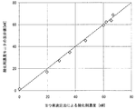
- Example 2 When the apparatus shown in FIG. 2 was operated and the oxidant concentration was stabilized, the iodine titration method was compared with an oxidant concentration monitor using absorbance.
- the operating condition of the apparatus was a sulfuric acid concentration of 80% by mass, and the sulfuric acid supplied to the washing machine was returned to the electrolytic electrolytic sulfuric acid apparatus in its entirety.
- the amount of current input was 280 Ah / L, and the total amount of liquid retained was 80 L.
- the absorbance at an absorbance of 254 nm was measured, and the baseline was 80% by mass sulfuric acid. Measurements were made every 30 minutes for 5 hours from the operation of the apparatus. The results are shown in FIG. From this, it was confirmed that the oxidant concentration monitor using the absorbance almost coincided with the measured value by the iodine titration method.
Landscapes
- Chemical & Material Sciences (AREA)
- Physics & Mathematics (AREA)
- Engineering & Computer Science (AREA)
- Chemical Kinetics & Catalysis (AREA)
- Electrochemistry (AREA)
- Materials Engineering (AREA)
- Metallurgy (AREA)
- Organic Chemistry (AREA)
- Spectroscopy & Molecular Physics (AREA)
- General Physics & Mathematics (AREA)
- Immunology (AREA)
- Pathology (AREA)
- Biochemistry (AREA)
- Health & Medical Sciences (AREA)
- Life Sciences & Earth Sciences (AREA)
- Analytical Chemistry (AREA)
- General Health & Medical Sciences (AREA)
- Mathematical Physics (AREA)
- Theoretical Computer Science (AREA)
- Inorganic Chemistry (AREA)
- Automation & Control Theory (AREA)
- Investigating Or Analysing Materials By Optical Means (AREA)
- Cleaning Or Drying Semiconductors (AREA)
- Manufacturing & Machinery (AREA)
Abstract
Description
前記電解硫酸の硫酸濃度と同じ硫酸濃度の電解硫酸調製液を標準試料液として全酸化性物質濃度と関連付けてベースライン補正した吸光度データを用いて、
硫酸濃度が60~97質量%、液温が20~70℃である電解硫酸を試料液として、波長190~290nmで吸光度測定することにより前記データに基づいて前記電解硫酸中の全酸化性物質濃度を測定することを特徴とする。
前記電解硫酸を前記第1または第2の発明の測定方法によって測定し、該電解硫酸溶液の全酸化性物質濃度をオンラインモニタリングすることを特徴とする。
前記電解装置を介在させて硫酸溶液を電解しつつ循環させる循環ラインと、
電解硫酸を使用して半導体基板を洗浄する基板洗浄装置と、
電解硫酸を基板洗浄装置に送る供給ラインと、
吸光光度計と、
電解硫酸の硫酸濃度と同じ硫酸濃度の電解硫酸調製液を標準試料液として全酸化性物質濃度と関連付けてベースライン補正した吸光度データを保持する記憶部と、
電解硫酸を前記電解装置、循環ライン、供給ラインのいずれかから一部を取り出して、前記吸光光度計に分岐する分岐ラインと、
前記吸光光度計で、硫酸濃度が60~97質量%、液温が20~70℃の前記電解硫酸を試料液として、波長190~290nmで吸光度測定することによって得られるデータと、前記ベースライン補正をしたデータとに基づいて前記電解硫酸溶液の全酸化性物質濃度を測定する測定器とを備えることを特徴とする。
なお、硫酸を電解した電解硫酸液中にはペルオキソ二硫酸、ペルオキソ一硫酸、過酸化水素といった酸化性物質が混在する。ペルオキソ二硫酸、ペルオキソ一硫酸、過酸化水素はいずれも190~290nm付近に吸光ピークを示すが、モル吸光係数が異なるため、混在状態では全体量を把握することは通常できない。しかし、これらの酸化性物質は電解硫酸では下式(2)(3)の通り平衡関係で存在するため、硫酸濃度60~97質量%で、かつ液温が室温~70℃程度であれば、平衡関係により、混在する酸化性物質の存在割合はほぼ一定となる。これにより混在状態でも吸光度による測定が可能となる。
H2S2O8+H2O ←→ H2SO5+H2SO4 (2)
H2SO5+H2O ←→ H2O2+H2SO4 (3)
2HSO4 - → H2S2O8+2e- (1)
また、ペルオキソ二硫酸から式(2)に示す平衡反応でペルオキソ一硫酸が生成し、さらには式(3)に示す平衡反応で過酸化水素が生成する。従って硫酸の電解液中にはペルオキソ二硫酸、ペルオキソ一硫酸、過酸化水素といった酸化性物質が混在するが、これらはいずれもヨウ素滴定法などによって定量することが可能であるため、電解液中に含まれる全酸化性物質濃度を本滴定法で把握することが可能である。ここではペルオキソ二硫酸とペルオキソ一硫酸を総称して過硫酸とする。
H2S2O8+H2O ←→ H2SO5+H2SO4 (2)
H2SO5+H2O ←→ H2O2+H2SO4 (3)
硫酸濃度70質量%、85質量%、92質量%の溶液を、室温にて導電性ダイヤモンド電極を使って電気分解し、投入電流を10[Ah/L]とした電解硫酸溶液について、電解直後の溶液を40[℃/hr]の速度で70℃まで徐々に昇温した。電解直後の酸化剤濃度を測定したところ、38[mM]、26[mM]、11[mM]であった。
ここで、30℃、40℃、50℃、70℃について吸光度を測定した結果、図1に示すように温度変化による吸光度の影響は殆ど認められなかった。したがって、硫酸濃度70~92質量%の電解硫酸については、電解直後から存在する酸化性物質の存在割合は、室温~70℃まではほぼ一定になっていると判断できる。
硫酸濃度の計測方法は本発明としては特に指定する必要はなく、音速計測式によるもの、共鳴振動式によるものなど、オンラインで計測可能なものであればいずれでもよい。測定液の硫酸濃度と吸光強度から酸化剤濃度を演算する方法、事前に所定の硫酸濃度で吸光強度と酸化剤濃度の関係を計測し、所定の硫酸濃度のみで酸化剤濃度を計測する方法のいずれも可能である。本原理を用いれば、電解硫酸装置における酸化剤濃度のオンラインモニタリングが可能である。
一般に吸収スペクトルを測定する場合,まず試料側,対照側ともに同一試料(通常は水あるいは緩衝液)を入れて,吸光度を波長に対して記録させる。これをベースラインと呼び、原理的には吸光度ゼロの直線が引かれるが、使用しているセルのマッチングが悪かったり、セルの微少な汚れやキズ、ビームの光強度、検知器への測定光の入射角度のずれ、等で凸凹を示す。大半の市販自記分光光度計は、このベースラインをまず測定器本体のコンピュータに記憶させて、吸光度0の値として補正する。次に試料側に測定したい試料を入れて波長をスキャンし、対照試料に対する吸収曲線(ベースライン)から引いて、試料の吸収スペクトルとする。
本実施形態においては、被洗浄材を洗浄する洗浄液の硫酸濃度が決まれば、設定された硫酸濃度の硫酸溶液をベースラインとして吸光度を測定することができる。
基板洗浄システム1は、硫酸溶液を通液しつつ電解する電解装置2と、硫酸溶液(電解後の電解硫酸溶液を含む)を貯留する貯留槽3とが循環ライン4で接続されている。
電解装置2は無隔膜型であり、陽極および陰極が隔膜で隔てることなく内部に配置され、両電極には図示しない直流電源が接続されている。陽極、陰極のうち、少なくとも陽極では硫酸溶液と接液する部分をダイヤモンド電極とするのが望ましい。なお、本発明としては、電解装置を隔膜型によって構成することも可能であり、バイポーラ電極を備えるものであってもよく、バイポーラ電極をダイヤモンド電極で構成するものであってもよい。
貯留槽3から電解装置2に至る送り側の循環ライン4には、送液ポンプ5と冷却器6とがこの順で介設されている。電解装置2から貯留槽3に至る、戻り側の循環ライン4には気液分離槽7が介設されている。
また、貯留槽3では、純水を貯留槽3内に導入する純水供給ライン8と、濃硫酸を貯留槽3内に導入する濃硫酸供給ライン9とが接続されており、システム立ち上げ時や稼働中に純水や濃硫酸を貯留槽3に供給することができる。稼働中の供給では、貯留槽内の硫酸濃度の調整を図ることができる。
過硫酸送液ポンプ11と加熱器17との間の供給ライン10には、フィルタ12、予備加熱槽13がこの順に接続されている。フィルタ12は、送液される過硫酸含有の硫酸溶液中に含まれる粒子を捕捉して除去する。予備加熱槽13は、貯留槽3から送られる溶液を貯留して加熱するものであり、溶液を例えば90~120℃に加熱する。
また、予備加熱槽13と加熱器17との間の供給ライン10では、供給ライン10を流れる電解溶液の一部を取り出す分岐ライン14が分岐して接続されており、該分岐ライン14は、酸化剤濃度モニタリング装置15に接続されている。酸化剤濃度モニタリング装置15に導入された溶液は、戻しライン16によって予備加熱槽13と加熱器17との間の供給ライン10であって分岐位置よりも上流側で、予備加熱槽13または供給ライン10に送られるように構成されている。酸化剤濃度モニタリング装置15は、本発明の測定器に相当し、吸光光度計15aと、電解硫酸の硫酸濃度と同じ硫酸濃度の電解硫酸調製液を標準試料液として全酸化性物質濃度と関連付けてベースライン補正した吸光度データを保持する不揮発の記憶部15bと、酸化剤濃度モニタリング装置15全体を制御する制御部15cとを備えている。記憶部15bには、フラッシュメモリやHDD、また着脱自在なUSBメモリなどを用いることができる。
また、戻りライン25には、未使用回収槽24から貯留槽3に掛けて、環流送液ポンプ26、フィルタ27、冷却器28がこの順に介設されている。
酸化剤濃度モニタリング装置15では、予め分岐ライン14で導入される電解硫酸と同じ硫酸濃度の電解硫酸調整液を標準試料液として全酸化性物質濃度と関連付けてベースライン補正した吸光度に関するデータを記憶部15bに保持しておく。この際の硫酸濃度は60~97質量%で、液温が20~70℃、波長190~290nmの範囲内から選択される。なお、硫酸濃度は、予め貯留槽3で用意されたものが使用される。なお、電解硫酸の溶液温度は、予備加熱槽13に備えた(図示していない)温度計で測定したり、酸化剤濃度モニタリング装置15に備えた(図示していない)温度計で測定したりすることで取得することができる。
貯留槽3には、硫酸濃度60~97質量%の硫酸溶液が貯留される。硫酸濃度は、純水供給ライン8と濃硫酸供給ライン9との溶液供給により調整することができる。
前記硫酸溶液は、送液ポンプ5により循環ライン4を通じて送液され、電解装置2の入液側に導入される。電解装置2では、直流電源によって陽極、陰極間に通電され、電解装置2内に導入された硫酸溶液が電解される。なお、該電解によって電解装置1では、陽極側で過硫酸を含む酸化性物質が生成される。
予備加熱槽13内の電解硫酸は、供給ライン10を通って加熱器17に送られて、例えば140~220℃に加熱され、例えば加熱後、1分以内に半導体基板100に接触させて枚葉式の洗浄を行う。なお、洗浄に使用された洗浄液は、半導体基板100に接触した後、排液ライン21、系外排出ライン22を通して、掛け捨てにより系外に排出する。
なお、本実施形態としては、酸化剤濃度の測定に用いた電解硫酸を戻す位置は特定の位置に限定されるものではないが、測定地点よりも上流側に戻すのが望ましい。これにより、システムに対する影響を小さくして測定に用いた電解硫酸を再利用することができる。
80質量%に調整した硫酸を電気分解し、濃度の異なる酸化剤を含有した硫酸電解液について、200~300nmの吸光強度を80質量%硫酸をベースラインとして計測した。酸化剤濃度はヨウ素滴定法によって分析した。電気分解は導電性ダイヤモンド電極を陽極および陰極に使用し、投入電流量を0,5,10,15[Ah/L]とした電解硫酸溶液である。各電解硫酸溶液でのスペクトラムを図3に示す。このように酸化剤濃度が高くなるほど、200~300nmの領域で吸光強度が高くなっている。
図2に示す装置を稼働し、酸化剤濃度が安定したところで、ヨウ素滴定法と吸光度を利用した酸化剤濃度モニタによる比較を行った。なお、装置の稼働条件は硫酸濃度80質量%であり、洗浄機へ供給した硫酸は全量電解硫酸装置に戻した。電流投入量は280Ah/Lであり、全体の保有液量は80Lとした。酸化剤濃度モニタリング装置では、吸光度254nmでの吸光強度を計測し、ベースラインは80質量%硫酸とした。装置稼働から5時間、30分毎にそれぞれ測定した。結果を図5に示す。これより、吸光度を利用した酸化剤濃度モニタは、ヨウ素滴定法による測定値にほぼ一致することが確認できた。
2 電解装置
3 貯留槽
4 循環ライン
10 供給ライン
13 予備加熱槽
14 分岐ライン
15 酸化剤濃度モニタリング装置
15a 吸光光度計
16 戻しライン
15b 記憶部
20 枚葉式洗浄装置
Claims (7)
- 電解硫酸の全酸化性物質濃度を測定する方法であって、
前記電解硫酸の硫酸濃度と同じ硫酸濃度の電解硫酸調製液を標準試料液として全酸化性物質濃度と関連付けてベースライン補正した吸光度データを用いて、
硫酸濃度が60~97質量%、液温が20~70℃である電解硫酸を試料液として、波長190~290nmで吸光度測定することにより前記データに基づいて前記電解硫酸中の全酸化性物質濃度を測定することを特徴とする全酸化性物質濃度の測定方法。 - 前記全酸化性物質は、ペルオキソ一硫酸、ペルオキソ二硫酸、過酸化水素を含むことを特徴とする請求項1記載の全酸化性物質濃度の測定方法。
- 硫酸溶液を電解しつつ循環させて電解濃度を高め、電解濃度を高めた電解硫酸溶液を用いて半導体基板の洗浄を行う基板洗浄方法であって、
前記電解硫酸を請求項1または2の測定方法によって測定し、該電解硫酸溶液の全酸化性物質濃度をオンラインモニタリングすることを特徴とする基板洗浄方法。 - 前記電解硫酸が基板に接触する前に一部を試料液として系内から分岐して吸光度測定を行い、測定後の前記試料液を前記系内に戻すことを特徴とする請求項3記載の基板洗浄方法。
- 基板洗浄に用いた洗浄廃液は循環再利用せず掛け捨てとし、電解液を循環するラインから電解硫酸溶液を基板洗浄に供給する供給ラインのいずれかの位置において電解硫酸の一部を試料液として分岐して吸光度測定を行って全酸化性物質濃度を測定し、測定後に基板洗浄の前の位置で前記試料液を系内に返送することを特徴とする請求項3または4に記載の基板洗浄方法。
- 測定後の電解硫酸は、供給ラインから分岐した位置よりも上流側に返送することを特徴とする請求項5記載の基板洗浄方法。
- 硫酸溶液を電解する電解装置と、
前記電解装置を介在させて硫酸溶液を電解しつつ循環させる循環ラインと、
電解硫酸を使用して半導体基板を洗浄する基板洗浄装置と、
電解硫酸を基板洗浄装置に送る供給ラインと、
吸光光度計と、
電解硫酸の硫酸濃度と同じ硫酸濃度の電解硫酸調製液を標準試料液として全酸化性物質濃度と関連付けてベースライン補正した吸光度データを保持する記憶部と、
電解硫酸を前記電解装置、循環ライン、供給ラインのいずれかから一部を取り出して、前記吸光光度計に分岐する分岐ラインと、
前記吸光光度計で、硫酸濃度が60~97質量%、液温が20~70℃の前記電解硫酸を試料液として、波長190~290nmで吸光度測定することによって得られるデータと、前記ベースライン補正をしたデータとに基づいて前記電解硫酸溶液の全酸化性物質濃度を測定する測定器とを備えることを特徴とする基板洗浄システム。
Priority Applications (5)
| Application Number | Priority Date | Filing Date | Title |
|---|---|---|---|
| JP2015510550A JP6024936B2 (ja) | 2013-07-23 | 2014-06-23 | 全酸化性物質濃度の測定方法、基板洗浄方法および基板洗浄システム |
| US14/903,538 US10056248B2 (en) | 2013-07-23 | 2014-06-23 | Method for measuring overall concentration of oxidizing substances, substrate cleaning method, and substrate cleaning system |
| CN201480041784.0A CN105452845B (zh) | 2013-07-23 | 2014-06-23 | 总氧化性物质浓度的测定方法、基板清洗方法以及基板清洗系统 |
| KR1020157035628A KR101791490B1 (ko) | 2013-07-23 | 2014-06-23 | 전산화성 물질 농도의 측정 방법, 기판 세정 방법 및 기판 세정 시스템 |
| TW103125031A TWI585388B (zh) | 2013-07-23 | 2014-07-22 | 總氧化性物質濃度的測定方法、基板洗淨方法及基板洗淨系統 |
Applications Claiming Priority (2)
| Application Number | Priority Date | Filing Date | Title |
|---|---|---|---|
| JP2013152603 | 2013-07-23 | ||
| JP2013-152603 | 2013-07-23 |
Publications (1)
| Publication Number | Publication Date |
|---|---|
| WO2015012041A1 true WO2015012041A1 (ja) | 2015-01-29 |
Family
ID=52393094
Family Applications (1)
| Application Number | Title | Priority Date | Filing Date |
|---|---|---|---|
| PCT/JP2014/066522 Ceased WO2015012041A1 (ja) | 2013-07-23 | 2014-06-23 | 全酸化性物質濃度の測定方法、基板洗浄方法および基板洗浄システム |
Country Status (6)
| Country | Link |
|---|---|
| US (1) | US10056248B2 (ja) |
| JP (1) | JP6024936B2 (ja) |
| KR (1) | KR101791490B1 (ja) |
| CN (1) | CN105452845B (ja) |
| TW (1) | TWI585388B (ja) |
| WO (1) | WO2015012041A1 (ja) |
Cited By (4)
| Publication number | Priority date | Publication date | Assignee | Title |
|---|---|---|---|---|
| WO2016114188A1 (ja) * | 2015-01-14 | 2016-07-21 | 栗田工業株式会社 | 酸化剤濃度の測定方法および測定装置、並びに電子材料洗浄装置 |
| JP2016136139A (ja) * | 2015-01-14 | 2016-07-28 | 栗田工業株式会社 | 酸化剤濃度の測定方法および測定装置、並びに電子材料洗浄装置 |
| JP2017173218A (ja) * | 2016-03-25 | 2017-09-28 | 栗田工業株式会社 | 酸化剤濃度の測定方法及び測定装置、並びに電子材料洗浄装置 |
| JP2021008652A (ja) * | 2019-07-01 | 2021-01-28 | 富士電機株式会社 | 過酸化水素発生装置及び什器 |
Families Citing this family (7)
| Publication number | Priority date | Publication date | Assignee | Title |
|---|---|---|---|---|
| JP6752163B2 (ja) * | 2017-02-13 | 2020-09-09 | 東京エレクトロン株式会社 | 基板処理システム及び基板搬送方法 |
| CN109304128B (zh) * | 2017-07-26 | 2024-01-23 | 上海至纯洁净系统科技股份有限公司 | 设t型液体过滤器的药液配液系统及其清洗方法 |
| JP7072415B2 (ja) * | 2018-03-26 | 2022-05-20 | 株式会社Screenホールディングス | 基板処理方法および基板処理装置 |
| KR20200106636A (ko) | 2019-03-05 | 2020-09-15 | (주) 멀티패스 | 전도성 유체의 농도 측정장치 |
| JP7484389B2 (ja) | 2020-04-28 | 2024-05-16 | 栗田工業株式会社 | 樹脂成形体のエッチング方法及び樹脂成形体用エッチング処理システム |
| JP7484407B2 (ja) * | 2020-05-18 | 2024-05-16 | 栗田工業株式会社 | 電解硫酸溶液製造システムの立上げ方法 |
| JP2024116818A (ja) * | 2023-02-16 | 2024-08-28 | 株式会社Screenホールディングス | 基板処理装置、および、基板処理方法 |
Citations (2)
| Publication number | Priority date | Publication date | Assignee | Title |
|---|---|---|---|---|
| JP2012184951A (ja) * | 2011-03-03 | 2012-09-27 | Chlorine Engineers Corp Ltd | 酸化性物質の総濃度測定方法、酸化性物質の総濃度測定用濃度計およびそれを用いた硫酸電解装置 |
| JP2012189320A (ja) * | 2011-02-23 | 2012-10-04 | Kurita Water Ind Ltd | 過硫酸濃度の測定方法、過硫酸濃度測定装置、及び過硫酸供給装置 |
Family Cites Families (6)
| Publication number | Priority date | Publication date | Assignee | Title |
|---|---|---|---|---|
| JP4462146B2 (ja) * | 2004-09-17 | 2010-05-12 | 栗田工業株式会社 | 硫酸リサイクル型洗浄システムおよび硫酸リサイクル型過硫酸供給装置 |
| JP4600666B2 (ja) | 2005-03-29 | 2010-12-15 | 栗田工業株式会社 | 硫酸リサイクル型枚葉式洗浄システム |
| WO2007002580A2 (en) | 2005-06-23 | 2007-01-04 | Bioveris Corporation | Diagnostic as say system with multi -well reagent container |
| JP2008164504A (ja) | 2006-12-28 | 2008-07-17 | Chlorine Eng Corp Ltd | 電解硫酸中の酸化性成分の定量方法 |
| JP2011192779A (ja) * | 2010-03-15 | 2011-09-29 | Kurita Water Ind Ltd | 電子材料の洗浄方法および洗浄システム |
| EP2733724B1 (en) * | 2011-07-11 | 2017-05-24 | Kurita Water Industries Ltd. | Method for cleaning metal gate semiconductor |
-
2014
- 2014-06-23 CN CN201480041784.0A patent/CN105452845B/zh active Active
- 2014-06-23 KR KR1020157035628A patent/KR101791490B1/ko active Active
- 2014-06-23 WO PCT/JP2014/066522 patent/WO2015012041A1/ja not_active Ceased
- 2014-06-23 JP JP2015510550A patent/JP6024936B2/ja active Active
- 2014-06-23 US US14/903,538 patent/US10056248B2/en not_active Expired - Fee Related
- 2014-07-22 TW TW103125031A patent/TWI585388B/zh active
Patent Citations (2)
| Publication number | Priority date | Publication date | Assignee | Title |
|---|---|---|---|---|
| JP2012189320A (ja) * | 2011-02-23 | 2012-10-04 | Kurita Water Ind Ltd | 過硫酸濃度の測定方法、過硫酸濃度測定装置、及び過硫酸供給装置 |
| JP2012184951A (ja) * | 2011-03-03 | 2012-09-27 | Chlorine Engineers Corp Ltd | 酸化性物質の総濃度測定方法、酸化性物質の総濃度測定用濃度計およびそれを用いた硫酸電解装置 |
Cited By (5)
| Publication number | Priority date | Publication date | Assignee | Title |
|---|---|---|---|---|
| WO2016114188A1 (ja) * | 2015-01-14 | 2016-07-21 | 栗田工業株式会社 | 酸化剤濃度の測定方法および測定装置、並びに電子材料洗浄装置 |
| JP2016136139A (ja) * | 2015-01-14 | 2016-07-28 | 栗田工業株式会社 | 酸化剤濃度の測定方法および測定装置、並びに電子材料洗浄装置 |
| JP2017173218A (ja) * | 2016-03-25 | 2017-09-28 | 栗田工業株式会社 | 酸化剤濃度の測定方法及び測定装置、並びに電子材料洗浄装置 |
| WO2017163456A1 (ja) * | 2016-03-25 | 2017-09-28 | 栗田工業株式会社 | 酸化剤濃度の測定方法及び測定装置、並びに電子材料洗浄装置 |
| JP2021008652A (ja) * | 2019-07-01 | 2021-01-28 | 富士電機株式会社 | 過酸化水素発生装置及び什器 |
Also Published As
| Publication number | Publication date |
|---|---|
| US20160172185A1 (en) | 2016-06-16 |
| CN105452845A (zh) | 2016-03-30 |
| JPWO2015012041A1 (ja) | 2017-03-02 |
| KR101791490B1 (ko) | 2017-10-30 |
| TW201506378A (zh) | 2015-02-16 |
| CN105452845B (zh) | 2019-03-29 |
| JP6024936B2 (ja) | 2016-11-16 |
| KR20160033659A (ko) | 2016-03-28 |
| TWI585388B (zh) | 2017-06-01 |
| US10056248B2 (en) | 2018-08-21 |
Similar Documents
| Publication | Publication Date | Title |
|---|---|---|
| JP6024936B2 (ja) | 全酸化性物質濃度の測定方法、基板洗浄方法および基板洗浄システム | |
| JP5773132B2 (ja) | 過硫酸濃度の測定方法、過硫酸濃度測定装置、及び過硫酸供給装置 | |
| US9852921B2 (en) | Substrate treating apparatus and method of treating substrate | |
| JP2016162963A (ja) | 液中の金属イオン濃度の測定方法および測定装置並びに電子デバイスの洗浄システム | |
| JP5770491B2 (ja) | 酸化性物質の総濃度測定方法、酸化性物質の総濃度測定用濃度計およびそれを用いた硫酸電解装置 | |
| WO2016114188A1 (ja) | 酸化剤濃度の測定方法および測定装置、並びに電子材料洗浄装置 | |
| JP2013015387A (ja) | 水質分析計 | |
| JP5499602B2 (ja) | 有効酸化性物質の濃度測定方法 | |
| JP5979328B2 (ja) | 酸化剤濃度の測定方法および測定装置、並びに電子材料洗浄装置 | |
| US20090229995A1 (en) | Analysis of fluoride at low concentrations in acidic processing solutions | |
| KR102371965B1 (ko) | 다수의 실리콘 화합물의 선택적 모니터링 | |
| TW201307620A (zh) | 銅膜蝕刻工序控制方法及銅膜蝕刻液組合物的再生方法 | |
| JP2010243200A (ja) | 過酸化水素含有水溶液中の過酸化水素濃度の測定方法 | |
| JP6265289B1 (ja) | 酸化剤濃度測定装置及び酸化剤濃度測定方法 | |
| JP6168184B1 (ja) | 酸化剤濃度の測定方法及び測定装置、並びに電子材料洗浄装置 | |
| JP2003004726A (ja) | メッキ液の硫酸濃度測定方法 | |
| JP4809122B2 (ja) | 燐酸溶液中の珪素濃度測定装置及び測定方法 | |
| JP2008191159A (ja) | 比重及び成分濃度が変動する系の成分濃度分析方法、成分濃度分析装置及び成分濃度管理装置 | |
| Jung et al. | Quantitative Raman analysis of solution and degradation monitoring in H2O2-based CMP slurry | |
| KR101264463B1 (ko) | 식각액 관리 시스템, 식각 장치 및 이에 의한 식각액 관리방법 | |
| JP2007260516A (ja) | 硫酸過酸化水素洗浄液による洗浄方法、電気光学パネルの製造方法及び硫酸過酸化水素洗浄装置 | |
| JP4029815B2 (ja) | めっき装置、めっき液評価装置、めっき液の運用方法及びめっき液の評価方法 | |
| JPH05346402A (ja) | 薬液中のSi濃度モニタ装置 | |
| JP2004361180A (ja) | 比重及び成分濃度が変動する系の成分濃度分析方法、成分濃度分析装置及び成分濃度管理装置 | |
| JPH1151930A (ja) | Toc濃度の分析方法 |
Legal Events
| Date | Code | Title | Description |
|---|---|---|---|
| WWE | Wipo information: entry into national phase |
Ref document number: 201480041784.0 Country of ref document: CN |
|
| ENP | Entry into the national phase |
Ref document number: 2015510550 Country of ref document: JP Kind code of ref document: A |
|
| 121 | Ep: the epo has been informed by wipo that ep was designated in this application |
Ref document number: 14829803 Country of ref document: EP Kind code of ref document: A1 |
|
| ENP | Entry into the national phase |
Ref document number: 20157035628 Country of ref document: KR Kind code of ref document: A |
|
| WWE | Wipo information: entry into national phase |
Ref document number: 14903538 Country of ref document: US |
|
| NENP | Non-entry into the national phase |
Ref country code: DE |
|
| 122 | Ep: pct application non-entry in european phase |
Ref document number: 14829803 Country of ref document: EP Kind code of ref document: A1 |