WO2015008475A1 - 無線制御システム、通信装置、無線リソース制御方法及び記憶媒体 - Google Patents
無線制御システム、通信装置、無線リソース制御方法及び記憶媒体 Download PDFInfo
- Publication number
- WO2015008475A1 WO2015008475A1 PCT/JP2014/003716 JP2014003716W WO2015008475A1 WO 2015008475 A1 WO2015008475 A1 WO 2015008475A1 JP 2014003716 W JP2014003716 W JP 2014003716W WO 2015008475 A1 WO2015008475 A1 WO 2015008475A1
- Authority
- WO
- WIPO (PCT)
- Prior art keywords
- base station
- communication
- ratio
- radio
- communication quality
- Prior art date
Links
- 238000004891 communication Methods 0.000 title claims abstract description 227
- 238000000034 method Methods 0.000 title claims description 40
- 238000001514 detection method Methods 0.000 claims abstract description 32
- 238000009826 distribution Methods 0.000 claims description 32
- 230000005540 biological transmission Effects 0.000 claims description 28
- 230000003247 decreasing effect Effects 0.000 claims description 3
- 230000007423 decrease Effects 0.000 abstract description 22
- 238000011946 reduction process Methods 0.000 description 6
- 238000010586 diagram Methods 0.000 description 3
- 238000005259 measurement Methods 0.000 description 2
- 238000010295 mobile communication Methods 0.000 description 2
- 238000005352 clarification Methods 0.000 description 1
- 238000004590 computer program Methods 0.000 description 1
- 230000001186 cumulative effect Effects 0.000 description 1
- 238000005315 distribution function Methods 0.000 description 1
- 230000000694 effects Effects 0.000 description 1
- 230000007774 longterm Effects 0.000 description 1
- 230000003287 optical effect Effects 0.000 description 1
- 239000013307 optical fiber Substances 0.000 description 1
- 239000004065 semiconductor Substances 0.000 description 1
Images


Classifications
-
- H—ELECTRICITY
- H04—ELECTRIC COMMUNICATION TECHNIQUE
- H04W—WIRELESS COMMUNICATION NETWORKS
- H04W16/00—Network planning, e.g. coverage or traffic planning tools; Network deployment, e.g. resource partitioning or cells structures
- H04W16/02—Resource partitioning among network components, e.g. reuse partitioning
- H04W16/06—Hybrid resource partitioning, e.g. channel borrowing
-
- H—ELECTRICITY
- H04—ELECTRIC COMMUNICATION TECHNIQUE
- H04W—WIRELESS COMMUNICATION NETWORKS
- H04W72/00—Local resource management
- H04W72/50—Allocation or scheduling criteria for wireless resources
- H04W72/54—Allocation or scheduling criteria for wireless resources based on quality criteria
- H04W72/542—Allocation or scheduling criteria for wireless resources based on quality criteria using measured or perceived quality
-
- H—ELECTRICITY
- H04—ELECTRIC COMMUNICATION TECHNIQUE
- H04W—WIRELESS COMMUNICATION NETWORKS
- H04W16/00—Network planning, e.g. coverage or traffic planning tools; Network deployment, e.g. resource partitioning or cells structures
- H04W16/24—Cell structures
- H04W16/32—Hierarchical cell structures
Definitions
- the present disclosure relates to a radio control system, a communication apparatus, a radio resource control method, and a storage medium.
- HetNet Heterogeneous Network
- a communication terminal communicating with a macro base station can be offloaded to a micro base station. Therefore, the system throughput can be improved by using HetNet.
- CRE Cell Range Expansion
- the communication terminal adds an offset to the received power of the signal transmitted from the micro base station.
- the area of communication terminals that can be connected to the micro base station is expanded, and as a result, the coverage of the micro base station is expanded.
- a communication terminal located in an area expanded by CRE has a problem that interference caused by a signal transmitted from the macro base station becomes large. Therefore, in order to avoid interference, ABS (Almost Blank Subframe), which is a specific subframe for controlling data transmission from the macro base station, is used.
- ABS Almost Blank Subframe
- Patent Documents 1 and 2 disclose a configuration of a mobile communication network that reduces interference caused by a signal transmitted from a macro base station in a micro base station by using ABS.
- the macro base station cannot perform data transmission in the subframe in which the ABS is set. Therefore, when the number of frames in which ABS is set is too large, there is a problem that the throughput in the macro base station is lowered. On the other hand, when the number of frames in which the ABS is set is too small, there is a problem in that interference generated in the micro base station cannot be removed and throughput in the micro base station is reduced.
- One of the objects of exemplary embodiments of the present invention is to avoid a decrease in throughput in a macro base station and a micro base station, or to suppress interference generated in a micro base station, and a radio control system and communication
- An apparatus, a radio resource control method, and a storage medium are provided. It should be noted that this object is only one of a plurality of objects that the embodiments disclosed herein intend to achieve. Other objects or problems and novel features will become apparent from the description of the present specification or the accompanying drawings.
- the radio control system of an exemplary embodiment includes a first base station that forms a first communication area, a second base station that forms a second communication area included in the first communication area, A detection unit that detects communication quality between the second base station and a communication terminal located in the second communication area, and data transmission in the first base station is limited based on the communication quality And a control unit that controls the ratio of the radio resources that have been transmitted.
- the communication apparatus of the exemplary embodiment is configured to perform communication based on communication quality with a communication terminal located in a second communication area included in the first communication area formed by the first base station. It has a control part which controls the rate of the radio resource in which data transmission in one base station was restricted.
- the radio resource control method of the exemplary embodiment is based on communication quality with a communication terminal located in a second communication area included in the first communication area formed by the first base station, The ratio of radio resources for which data transmission in the first base station is restricted is controlled.
- the storage medium of the exemplary embodiment is based on communication quality with a communication terminal located in a second communication area included in the first communication area formed by the first base station.
- a program for causing a computer to execute a process for controlling a ratio of radio resources limited in data transmission in one base station is stored.
- a radio control system, a communication apparatus, and a radio that can avoid a decrease in throughput in a macro base station and a micro base station, or can suppress interference generated in a micro base station.
- a resource control method and a storage medium can be provided.
- FIG. 1 is a configuration diagram of a radio control system according to an exemplary embodiment 1.
- FIG. It is a block diagram of the micro base station concerning exemplary Embodiment 2.
- FIG. FIG. 6 is a diagram of a macro base station according to an exemplary embodiment 2. It is a figure explaining the structure of the sub-frame concerning exemplary Embodiment 2.
- FIG. It is a figure explaining the structure of the sub-frame concerning exemplary Embodiment 2.
- FIG. It is a figure explaining the flow of a process which detects the number of RLF concerning exemplary Embodiment 2.
- FIG. It is a figure explaining the flow of the control processing of the radio
- FIG. It is a figure of the ABS ratio management table concerning exemplary Embodiment 2.
- FIG. 2 It is a figure of the threshold value management table concerning exemplary Embodiment 2.
- FIG. It is a figure explaining the flow of the ABS ratio increase process concerning exemplary Embodiment 2.
- FIG. It is a figure of the threshold value management table concerning exemplary Embodiment 2.
- FIG. It is a figure explaining the flow of the ABS ratio reduction process concerning exemplary Embodiment 2.
- FIG. It is a figure explaining the flow of the measurement process of CQI distribution concerning illustrative Embodiment 3.
- FIG. It is a figure explaining the flow of the control processing of the radio
- FIG. It is a figure explaining the flow of the ABS ratio increase process concerning illustrative Embodiment 3.
- FIG. It is a figure explaining the flow of the ABS ratio reduction process concerning illustrative Embodiment 3.
- FIG. It is a figure explaining the flow of the ABS ratio increase process concerning illustrative Embodiment 3.
- FIG. It
- FIG. 1 A configuration example of a radio control system according to an exemplary embodiment 1 will be described with reference to FIG.
- the radio control system in FIG. 1 includes a macro base station 101 and a micro base station 102.
- the macro base station 101 forms a macro cell 103.
- the micro base station 102 forms a pico cell 105.
- the micro base station 102 can expand the pico cell 105 to the expansion area 106 by using the CRE.
- the radio control system of FIG. 1 shows a HetNet environment, and a pico cell 105 is arranged in an overlay manner in a macro cell 103. That is, the pico cell 105 and the extended area 106 are formed so as to be included in the macro cell 103.
- the micro base station may be referred to as a femto base station, and the pico cell 105 may be referred to as a micro cell, a femto cell, or the like.
- the macro base station 101 communicates with the communication terminal 201
- the micro base station 102 communicates with the communication terminals 202 and 203 located in the pico cell 105 or the extended area 106.
- the figure a configuration example in which one communication terminal is located in each of the macro cell 103, the pico cell 105, and the extension cell 106 is shown.
- each of the macro cell 103, the pico cell 105, and the extension cell 106 includes a plurality of communication terminals. May be in the area.
- the macro base station 101 and the micro base station 102 are connected via a communication interface 104.
- the macro base station 101 and the micro base station 102 transmit and receive RLF (Radio Link Failure) information, ABS information, and the like indicating a radio link failure between each base station and the communication terminal.
- RLF Radio Link Failure
- the radio control system may include a management device 110.
- the management device 110 may be a base station control device or a gateway device that is a host device of the macro base station 101 and the micro base station 102.
- the management device 110 may be an EMS (Element Management System) that manages the macro base station 101 and the micro base station 102.
- the management device 110 includes a communication quality detection unit 111 and a radio resource control unit 112.
- the management apparatus 110 has shown the structure which has the communication quality detection part 111 and the radio
- other apparatuses are the communication quality detection part 111 and the radio
- the micro base station 102 may include the communication quality detection unit 111
- the macro base station 101 may include the radio resource control unit 112.
- the communication quality detection unit 111 detects the communication quality between the micro base station 102 and the communication terminals 202 and 203 located in the pico cell 105 or the extended area 106.
- the communication quality detected by the communication quality detection unit 111 is between the micro base station 102 and the communication terminal 202 located in the pico cell 105 or between the micro base station 102 and the communication terminal 203 located in the extension area 106. May be an RLF indicating a radio link failure.
- the communication quality detected by the communication quality detection unit 111 may be a CQI (Channel Quality Interdictor) distribution, a SINR (Signal-to-Interference-and-Noise-power Ratio) value, an MCS (Modulation-and-Coding-Scheme) distribution, or the like.
- CQI Channel Quality Interdictor
- SINR Signal-to-Interference-and-Noise-power Ratio
- MCS Modulation-and-Coding-Scheme
- the radio resource control unit 112 controls restrictions on the use of radio resources in the macro base station 101 based on the communication quality detected by the communication quality detection unit 111.
- the radio resource whose use is restricted indicates, for example, a radio resource used in radio communication between the communication terminal 201 and the macro base station 101.
- Control of restriction on the use of radio resources in the macro base station 101 may be performed, for example, by controlling an ABS pattern.
- the macro base station 101 uses ABS in order to avoid interference that a signal transmitted from the macro base station 101 gives to the communication terminals 202 and 203 located in the pico cell 105 or the extended area 106. Thereby, the micro base station 102 can reduce the interference in the subframe corresponding to the ABS, and can improve the throughput in the subframe corresponding to the ABS.
- the communication terminal 201 communicates with the macro base station 101 using a subframe other than the subframe corresponding to the ABS according to the ABS pattern controlled by the radio resource control unit 112.
- the radio resource control unit 112 controls the ratio of radio resources whose use is restricted, that is, the ratio at which ABS is set. For example, when the rate at which the radio resource control unit 112 sets the ABS is increased, interference given to the communication terminals 202 and 203 located in the pico cell 105 or the extended area 106 can be reduced. Decreases.
- the throughput in the macro base station 101 is improved, but the interference given to the communication terminals 202 and 203 located in the pico cell 105 or the extension area 106 is increased. It will be.
- the radio resource control unit 112 uses the communication quality detected by the radio resource control unit 112, and the interference that the signal transmitted from the macro base station 101 gives to the pico cell 105 or the extension area 106, the throughput in the macro base station 101, And control the ratio of radio resources that are restricted in use.
- the communication quality detection unit 111 is connected between the micro base station 102 and the communication terminal 202 located in the pico cell 105 or between the micro base station 102 and The communication quality with the communication terminal 203 located in the extended area 106 can be detected. Furthermore, the radio resource control unit 112 can control the ratio of radio resources whose use is restricted in the macro base station 101 according to the communication quality. Therefore, the radio resource control unit 112 optimizes the interference that the signal transmitted from the macro base station 101 gives to the pico cell 105 or the extension area 106 and the throughput in the macro base station 101 using the detected communication quality. Thus, it is possible to control the ratio of radio resources whose use is restricted.
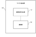
- the micro base station 120 includes a communication quality detection unit 121 and a communication unit 122.
- FIG. 1 the configuration in which the communication quality detection unit 111 is mounted on a management device different from the micro base station 102 has been described.
- the micro base station 120 has a communication quality detection unit 121.
- the micro base station 120 forms the pico cell 105 and the extended area 106 as in FIG.
- the communication quality detection unit 121 detects the communication quality with the communication terminal located in the pico cell 105 or the extended area 106. Hereinafter, a specific example of communication quality will be described using the number of RLFs.
- the communication quality detection unit 121 detects the number of RLFs generated in a communication terminal located in the pico cell 105 or the extended area 106.
- the number of RLFs may be the number of RLF occurrences (detection number) or the number of call disconnections.
- a communication terminal located in the pico cell 105 or the expansion area 106 is connected to the micro base station 120.
- the connection indicates a state in which the communication terminal can communicate with the micro base station 120, for example.
- the communication quality detection unit 121 detects the number of RLFs for each communication terminal connected to the micro base station 120 for a certain period. Furthermore, the communication quality detection unit 121 aggregates the number of RLFs detected for each communication terminal and generates statistical information. The statistical information indicates the number of RLFs generated in a certain period in all communication terminals connected to the micro base station 120. The communication quality detection unit 121 outputs the detected statistical information on the number of RLFs to the communication unit 122.
- the communication unit 122 transmits statistical information regarding the number of RLFs to the macro base station 130 via the communication interface 104.
- the communication interface 104 for example, an X2 interface defined as an interface between base stations in 3GPP (3rd Generation Generation Partnership Project) may be used.
- the macro base station 130 includes a communication unit 131 and a radio resource control unit 132.
- FIG. 1 the configuration in which the radio resource control unit 112 is mounted on a management apparatus different from the macro base station 101 has been described.
- the configuration in which the macro base station 130 includes the radio resource control unit 132 is described.
- the macro base station 130 forms the macro cell 103 as in FIG.
- the communication unit 131 receives statistical information regarding the number of RLFs transmitted from the micro base station 120 via the communication interface 104.
- the communication unit 131 outputs statistical information regarding the received RLF number to the radio resource control unit 132.
- the radio resource control unit 132 uses the statistical information regarding the number of output RLFs to calculate the ABS ratio (hereinafter, ABS ratio) to be set in the subframe.
- ABS ratio the ABS ratio
- an ABS ratio will be described.
- the ABS defined in 3GPP can set any setting pattern of ABS set in 40 subframes with 40 subframes as one cycle.
- # 0 to # 39 indicate subframe numbers.
- the micro base station 120 and the macro base station 130 set an ABS setting pattern in the broadcast information, and notify each communication terminal of the ABS setting pattern.
- FIG. 4 shows an example in which ABS is set at 8 subframe intervals. In this case, the ABS ratio is 1/8 for all subframes.
- FIG. 5 shows an example in which the ABS is set at an interval of 4 subframes. In this case, the ABS ratio is 1/4 for all subframes.
- the communication unit 131 transmits the ABS setting pattern to the communication terminals located in the macro cell 103 using the broadcast information.
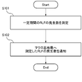
- the communication quality detection unit 121 measures the number of occurrences of RLF in a certain period (S101). For example, the communication quality detection unit 121 may measure the number of RLFs generated in a certain period for each communication terminal located in the pico cell 105 or the extended area 106, and aggregate the measurement results to generate statistical information. .
- the communication unit 122 transmits statistical information about the number of RLFs to the macro base station 130 via the X2 interface (S102).
- the radio resource control unit 132 performs an ABS ratio increasing process using the number of RLFs acquired via the communication unit 131 (S201).
- the number of RLFs acquired by the radio resource control unit 132 via the communication unit 131 is the number of RLFs generated in the micro base station 120 in a certain period.
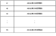
- the ABS ratio management table in FIG. 8 is a table for managing a plurality of ABS ratios.
- N values of 1/8 to N / 8 are managed as candidates for the ABS ratio to be set.
- the ABS ratio in the ABS ratio management table of FIG. 8 can be changed. That is, the administrator or the like can rewrite the ABS ratio value in the ABS ratio management table.
- the threshold management table in FIG. 9 is a table for managing thresholds used when the ABS ratio increasing process is performed.
- the ABS ratio increase determination threshold 1 is used when determining whether or not to change the ABS ratio from 0 to 1/8.
- the ABS ratio increase determination threshold 2 is used when determining whether or not to change the ABS ratio from 1/8 to 2/8.
- the ABS ratio increase determination threshold N is used when determining whether to change the ABS ratio from (N ⁇ 1) / 8 to N / 8.
- the threshold value is a specific numerical value for comparison with the RLF number.
- the ABS ratio increase determination threshold increases as the ABS ratio increase determination threshold 1 changes from the ABS ratio increase determination threshold N.
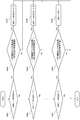
- the radio resource control unit 132 determines whether or not ABS is currently applied (S301). If the current ABS is not applied, step S304 is executed, and if the current ABS is applied, step S302 is executed. In step S304, the radio resource control unit 132 compares the number of RLFs notified from the micro base station 120 with “ABS ratio increase determination threshold value 1”. If the number of RLFs is larger than the ABS ratio increase determination threshold value 1, the radio resource control unit 132 sets the ABS ratio to “ABS ratio 1/8” (S307). If the number of RLFs is not greater than the ABS increase determination threshold value 1, the radio resource control unit 132 ends without applying the ABS.
- step S302 the radio resource control unit 132 determines whether or not the currently applied ABS ratio is “ABS ratio 1/8”. If “ABS ratio 1/8”, step S305 is executed. In step S305, the radio resource control unit 132 compares the number of RLFs notified from the micro base station 120 with “ABS ratio increase determination threshold 2”, as in step S304. If the number of RLFs is greater than the ABS ratio increase determination threshold 2, the radio resource control unit 132 sets the ABS ratio to “ABS ratio 2/8” (S308). When the number of RLFs is smaller than the ABS increase determination threshold value 2, the radio resource control unit 132 ends without changing the ABS ratio.
- step S302 if the currently applied ABS ratio is not “ABS ratio 1/8”, the radio resource control unit 132 similarly determines whether to change the ABS ratio according to the currently applied ABS ratio, If necessary, as shown in step S303, determination is made up to “ABS ratio (N ⁇ 1) / 8”.
- the ABS ratio currently applied between Step 302 and Step S303 is “ABS ratio 2/8”, “ABS ratio 3/8”, “ABS ratio 4/8”, “ABS ratio 5/8”.
- a determination process for determining whether “ABS ratio 6/8”, “ABS ratio 7/8” or “ABS ratio 8/8” may be executed.
- step S303 the radio resource control unit 132 determines whether or not the currently applied ABS ratio is “ABS ratio (N ⁇ 1) / 8”. If “ABS ratio (N-1) / 8", step S306 is executed. If not "ABS ratio (N-1) / 8" (that is, "ABS ratio N / 8"), an ABS change determination is made. The process ends without being performed.
- step S306 similarly to steps S304 and S305, the radio resource control unit 132 compares the number of RLFs notified from the micro base station 120 with the “ABS ratio increase determination threshold N”, and determines that the RLF number is the ABS ratio increase determination. If it is larger than the threshold value N, the ABS ratio is set to “ABS ratio N / 8” (S309). When the number of RLFs is smaller than the ABS increase determination threshold value N, the radio resource control unit 132 ends without changing the ABS ratio.
- the radio resource control unit 132 determines whether or not the ABS ratio has been changed in Step S201.
- the radio resource control unit 132 proceeds to step S204 when the ABS ratio is changed, and proceeds to step S203 when the ABS ratio is not changed.
- step S203 an ABS ratio reduction process is performed.
- the ABS ratio reduction process in step S203 will be described in detail with reference to FIGS.
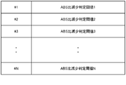
- the threshold management table in FIG. 11 is a table for managing thresholds used when the ABS ratio reduction process is performed.
- the ABS ratio decrease determination threshold 1 is used when determining whether or not to change the ABS ratio 1/8 from 0.
- the ABS ratio decrease determination threshold 2 is used when determining whether or not to change the ABS ratio from 2/8 to 1/8.
- the ABS ratio decrease determination threshold N is used when determining whether or not to change the ABS ratio from N / 8 to (N ⁇ 1) / 8.
- the threshold value is a specific numerical value for comparison with the RLF number.
- the ABS ratio decrease determination threshold increases as the ABS ratio decrease determination threshold 1 changes to the ABS ratio decrease determination threshold N.
- the ABS ratio decrease determination threshold value is set with hysteresis so as not to cause the process and the ping-pong phenomenon in step S201. That is, in step S201, the ABS ratio is changed to be increased, and when the processing of FIG. 7 is subsequently executed, the slight change in the number of RLFs is changed to immediately decrease the ABS ratio in step S203.
- An ABS ratio decrease determination threshold is set so that nothing happens.
- the ABS ratio decrease determination threshold N may be set to be smaller than the ABS ratio increase determination threshold N.
- the ABS ratio decrease determination threshold value and the ABS ratio increase determination threshold value may be the same value and may not be set with hysteresis.
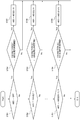
- the radio resource control unit 132 determines whether or not the currently applied ABS ratio is “ABS ratio N / 8” (S401). If the ABS ratio is “ABS ratio N / 8”, the process proceeds to step S404; otherwise, the process proceeds to step S402. In step S404, the radio resource control unit 132 compares the number of RLFs notified from the micro base station 120 with the “ABS ratio decrease determination threshold N”, and if the RLF number is smaller than the ABS ratio decrease determination threshold N, ABS ratio (N-1) / 8 "(S407). If the number of RLFs is not smaller than the ABS ratio decrease determination threshold value N, the radio resource control unit 132 ends without changing the ABS ratio.
- step S402 the radio resource control unit 132 determines whether or not the currently applied ABS ratio is “ABS ratio (N ⁇ 1) / 8”, and if it is “ABS ratio (N ⁇ 1) / 8”.
- Step S405 is executed.
- the radio resource control unit 132 compares the number of RLFs notified from the micro base station 120 with the “ABS ratio decrease determination threshold (N ⁇ 1)”. If the RLF count is smaller than the ABS ratio decrease determination threshold value (N ⁇ 1), the radio resource control unit 132 sets “ABS ratio (N ⁇ 2) / 8” (S408). If the RLF number is greater than the ABS ratio decrease determination threshold (N ⁇ 1), the radio resource control unit 132 ends without changing the ABS ratio.
- the radio resource control unit 132 similarly changes the ABS ratio according to the currently applied ABS ratio. A determination is made, and if necessary, a determination is made up to “ABS ratio 1/8” as shown in step S403.
- the ABS ratio currently applied between step 402 and step S403 is “ABS ratio 2/8”, “ABS ratio 3/8”, “ABS ratio 4/8”, “ABS ratio 5/8”. ”,“ ABS ratio 6/8 ”,“ ABS ratio 7/8 ”or“ ABS ratio 8/8 ”may be determined.
- step S406 If the currently set ABS ratio is the smallest “ABS ratio 1/8” in step S403, the process proceeds to step S406, and if it is not “ABS ratio 1/8” (ie, ABSAOFF), the ABS change determination is not performed. finish.
- step S406 as in steps S404 and S405, the number of RLFs notified from the micro base station 120 is compared with the “ABS ratio decrease determination threshold value 1”, and if the RLF number is smaller than the threshold value, the ABS is turned off ( S409). Otherwise, the process ends without changing the ABS ratio.
- step S204 the macro base station 120 controls data transmission according to the calculated ABS ratio.
- the ABS ratio decreasing process is performed in Step S203.
- the ABS ratio increasing process may be performed after the ABS ratio decreasing process is performed.
- the ABS ratio can be determined based on the number of RLFs. . Therefore, for example, when the number of RLFs is larger than the threshold value, a change setting such as increasing the ABS ratio is performed. In such a case, by increasing the ABS ratio, the influence of interference on the communication terminal located in the pico cell 105 or the extended area 106 is reduced. Therefore, the number of RLFs can be reduced. That is, by determining the ABS ratio based on the number of RLFs, the service impact due to RLF is reduced and the ABS can be optimized.
- the number of RLFs is used as a specific example of the communication environment.
- the estimated SINR value, reference signal received power (RSRP), reference signal received quality (RSRQ) is used.
- the same processing can be executed using Received (Quality) or the like.
- a communication terminal located in the pico cell 105 or the extended area 106 measures CQI, which is an index indicating the state of the radio propagation environment, using a reference signal transmitted from the micro base station 120.
- the communication quality detecting unit 121 aggregates CQI measured at a plurality of communication terminals and generates a CQI distribution.
- steps S501 and S502 of FIG. 13 the number of RLF occurrences in steps S101 and S102 of FIG. 6 is changed to the CQI distribution, and other contents are the same as steps S101 and S102 of FIG. Therefore, detailed description of steps S501 and S502 is omitted.
- FIG. 14 shows a flow of radio resource control processing in the macro base station 130 according to the exemplary embodiment 3.
- steps S601 to S604 in FIG. 14 the number of RLF occurrences in steps S201 to S204 in FIG. 7 is changed to the CQI distribution, and other contents are the same as those in steps S201 to S204 in FIG. Therefore, detailed description of steps S601 to S604 is omitted.
- steps S701 to S709 in FIG. 15 the number of RLF occurrences in steps S301 to S309 in FIG. 7 is changed to a parameter relating to the CQI distribution.
- the parameters relating to the CQI distribution will be described.
- the radio resource control unit 132 sets the ABS ratio increase determination threshold to a ratio (%) indicating the distribution ratio in order to compare the CQI distribution with the ABS ratio increase determination threshold.
- the ABS ratio increase determination threshold value increases as the ABS ratio increase determination threshold value 1 changes to the ABS ratio increase determination threshold value N.
- the radio resource control unit 132 uses a CDF (Cumulative Distribution Function) equal to or less than a predetermined CQI value M as a parameter related to the CQI distribution to be compared with the ABS ratio increase determination threshold.
- CDF Cumulative Distribution Function
- Steps S701 to S709 in FIG. 15 are the same as steps S301 to S309 in FIG. 7 except for the process of comparing the CDF of CQI M or less and the ABS ratio increase determination threshold, and thus detailed description thereof is omitted.
- FIG. 16 shows the flow of ABS ratio reduction processing according to an exemplary embodiment 3.
- Steps S801 to S809 in FIG. 16 are the same as steps S401 to S409 in FIG. 8 except that the number of RLF occurrences in steps S401 to S409 in FIG. 8 is changed to a parameter related to the CQI distribution.
- the parameters relating to the CQI distribution are the same as those described in FIG. Therefore, detailed description in FIG. 16 is omitted.
- the ABS ratio can be determined based on the CQI distribution. it can. Therefore, for example, when the number of CDFs having a CQI of M or less is larger than the threshold value, a change setting such as increasing the ABS ratio is performed. In such a case, by increasing the ABS ratio, the influence of interference on the communication terminal located in the pico cell 105 or the extended area 106 is reduced. Therefore, the distribution with CQI of M or less can be reduced. That is, by determining the ABS ratio based on the CQI distribution, the radio environment in the pico cell 105 and the extended area 106 is improved, and the ABS can be optimized.
- the CQI distribution is used as a specific example of the communication environment, but the same processing can be executed using the MCS (Modulation and Coding Scheme) distribution.
- MCS Modulation and Coding Scheme
- the embodiment has been described as a hardware configuration, but the embodiment is not limited to this.
- the exemplary embodiment can also realize processing in the micro base station 120, the macro base station 130, and the management apparatus 110 by causing a CPU (Central Processing Unit) to execute a computer program. )
- a CPU Central Processing Unit
- Non-transitory computer readable media include various types of tangible storage media (tangible storage medium).
- Examples of non-transitory computer-readable media include magnetic recording media (eg flexible disks, magnetic tapes, hard disk drives), magneto-optical recording media (eg magneto-optical discs), CD-ROMs (Read Only Memory), CD-Rs, CD-R / W, semiconductor memory (for example, mask ROM, PROM (Programmable ROM), EPROM (Erasable ROM), flash ROM, RAM (Random Access Memory)) are included.
- the program may also be supplied to the computer by various types of temporary computer-readable media. Examples of transitory computer readable media include electrical signals, optical signals, and electromagnetic waves.
- the temporary computer-readable medium can supply the program to the computer via a wired communication path such as an electric wire and an optical fiber, or a wireless communication path.
- a first base station that forms a first communication area, a second base station that forms a second communication area included in the first communication area, and the second base station A radio resource control system comprising: radio resource control means for controlling restriction of use of radio resources in the first base station based on communication quality with a communication terminal located in the second communication area.
- wireless resource control means performs the process which increases the ratio of the radio
- the wireless control system according to supplementary note 1, wherein when it is determined that the wireless resource is determined to be worse than the wireless resource, the ratio of wireless resources whose use is restricted in the first base station is increased.
- the radio control system according to any one of appendices 1 to 3, wherein a hysteresis is provided between the communication quality threshold value used for determining whether or not to reduce the resource ratio.
- the radio control system according to any one of supplementary notes 1 to 4, wherein control of restriction on use of radio resources in the first base station is performed by controlling an ABS pattern.
- the communication quality detection means includes the number of occurrences of Radio Link Failure (RLF), Channel Quality Indicator (CQI) distribution, Signal to Interference and Noise power Ratio (SINR) value, Modulation and Coding Scheme as the communication quality.
- RLF Radio Link Failure
- CQI Channel Quality Indicator
- SINR Signal to Interference and Noise power Ratio
- the radio control system according to any one of appendices 1 to 5, wherein at least one of (MCS) distributions is detected.
- MCS Mobile Broadband Service
- the radio in the first base station A communication apparatus having a radio resource control unit that controls restriction of resource use.
- the communication quality at least one of the number of occurrences of Radio Link Failure (RLF), Channel Quality Indicator (CQI) distribution, Signal to Interference and Noise power Ratio (SINR) value, and Modulation and Coding Scheme (MCS) distribution
- RLF Radio Link Failure
- CQI Channel Quality Indicator
- SINR Signal to Interference and Noise power Ratio
- MCS Modulation and Coding Scheme
- wireless resource control part sets the ratio of the radio
- the communication apparatus according to appendix 10, which executes processing. (Additional remark 12) Based on the communication quality with the communication terminal located in the 2nd communication area included in the 1st communication area formed by the 1st base station, the radio
- wireless in the said 1st base station A program that causes a computer to execute steps that control resource usage restrictions.
- Appendix 14 A first base station forming a first communication area; A second base station forming a second communication area included in the first communication area; A detection unit for detecting communication quality between the second base station and a communication terminal located in the second communication area; And a control unit that controls a ratio of radio resources in which data transmission in the first base station is restricted based on the communication quality.
- the controller is 15.
- the radio according to appendix 14 wherein when it is determined that the communication quality is worse than a predetermined first communication quality, the ratio of radio resources for which data transmission is restricted in the first base station is increased.
- Control system. (Appendix 16) The controller is 15. The radio according to appendix 14, wherein when it is determined that the communication quality is better than a predetermined second communication quality, the ratio of radio resources for which data transmission is restricted in the first base station is reduced.
- Control system. (Appendix 17) The communication quality threshold used for determining whether or not to increase the proportion of radio resources for which data transmission is restricted in the first base station, and the radio for which data transmission is restricted in the first base station 17.
- the radio control system according to any one of appendices 14 to 16, wherein a hysteresis is provided between the communication quality threshold value used for determining whether or not to reduce the resource ratio.
- Appendix 18 The radio control system according to any one of appendices 14 to 17, wherein the control of the ratio of radio resources for which data transmission is restricted in the first base station is performed by controlling an ABS pattern.
- the detector is As the communication quality, at least one of the number of occurrences of Radio Link Failure (RLF), Channel Quality Indicator (CQI) distribution, Signal to Interference and Noise power Ratio (SINR) value, and Modulation and Coding Scheme (MCS) distribution is detected.
- the wireless control system according to any one of appendices 14 to 18.
- As the communication quality at least one of the number of occurrences of Radio Link Failure (RLF), Channel Quality Indicator (CQI) distribution, Signal to Interference and Noise power Ratio (SINR) value, and Modulation and Coding Scheme (MCS) distribution is detected.
Landscapes
- Engineering & Computer Science (AREA)
- Computer Networks & Wireless Communication (AREA)
- Signal Processing (AREA)
- Quality & Reliability (AREA)
- Mobile Radio Communication Systems (AREA)
Abstract
Description
以下に説明される複数の実施形態は、独立に実施されることもできるし、適宜組み合わせて実施されることもできる。これら複数の実施形態は、互いに異なる新規な特徴を有している。したがって、これら複数の実施形態は、互いに異なる目的又は課題を解決することに寄与し、互いに異なる効果を奏することに寄与する。
(実施の形態1)
図1を用いて例示的な実施形態1にかかる無線制御システムの構成例について説明する。図1の無線制御システムは、マクロ基地局101及びマイクロ基地局102を有している。マクロ基地局101は、マクロセル103を形成する。マイクロ基地局102は、ピコセル105を形成する。さらにマイクロ基地局102は、CREを用いることにより、ピコセル105を拡張エリア106まで拡張することができる。図1の無線制御システムは、HetNet環境を示しており、マクロセル103内にピコセル105がオーバーレイする形で配置されている。つまり、ピコセル105及び拡張エリア106は、マクロセル103内に含まれるように形成される。また、マイクロ基地局は、フェムト基地局、さらに、ピコセル105は、マイクロセル、フェムトセル等と称されてもよい。さらに、マクロ基地局101は、通信端末201と通信を行い、マイクロ基地局102は、ピコセル105もしくは拡張エリア106に在圏する通信端末202及び203と通信を行う。本図においては、マクロセル103、ピコセル105及び拡張セル106にそれぞれ1台の通信端末が在圏する構成例を示しているが、マクロセル103、ピコセル105及び拡張セル106には、それぞれ複数の通信端末が在圏してもよい。
続いて、図2を用いて例示的な実施形態2にかかるマイクロ基地局120の構成例について説明する。マイクロ基地局120は、通信品質検出部121及び通信部122を有している。図1においては、通信品質検出部111が、マイクロ基地局102と異なる管理装置に搭載される構成について説明したが、本図においては、マイクロ基地局120が、通信品質検出部121を有する構成について説明する。また、マイクロ基地局120は、図1と同様に、ピコセル105及び拡張エリア106を形成する。
3GPPにおいて規定されるABSは、図4及び図5に示すように、40サブフレームを1周期とし、40サブフレーム内に設定されるABSの設定パターンを任意に設定することが出来る。#0~#39は、サブフレーム番号を示している。マイクロ基地局120及びマクロ基地局130は、報知情報にABSの設定パターンを設定し、各通信端末へABSの設定パターンを通知する。
無線リソース制御部132が通信部131を介して取得したRLF数は、マイクロ基地局120において一定期間に発生したRLF数である。
ステップS304では、無線リソース制御部132は、マイクロ基地局120から通知されたRLF数と、「ABS比増大判定閾値1」とを比較する。無線リソース制御部132は、RLF数がABS比増大判定閾値1よりも大きければ、ABS比を「ABS比1/8」とする(S307)。無線リソース制御部132は、RLF数がABS増大判定閾値1よりも大きくなければ、ABSを適用せずに終了する。
ここで、ステップS203におけるABS比の減少処理について、図11及び図12を用いて詳細に説明する。
続いて、図13を用いて例示的な実施形態3にかかるマイクロ基地局120におけるCQI分布の検出処理の流れについて説明する。以降、図13~16の説明においては、実施の形態2においてRLF数に関する説明を行った箇所を、CQIの分布に変更して説明する。
前述の実施形態の一部または全部は、以下の各付記のようにも記載することができる。しかしながら、以下の各付記は、あくまでも、本発明の単なる例示に過ぎず、本発明は、かかる場合のみに限るものではない。
(付記1)第1の通信エリアを形成する第1の基地局と、前記第1の通信エリアに含まれる第2の通信エリアを形成する第2の基地局と、前記第2の基地局と前記第2の通信エリアに在圏する通信端末との間の通信品質に基づいて、前記第1の基地局における無線リソースの使用の制限を制御する無線リソース制御手段と、を備える無線制御システム。
(付記2)前記無線リソース制御手段は、前記第1の基地局において使用を制限される無線リソースの割合を増加させる処理を実行する際に、前記通信品質が予め定められた第1の通信品質よりも悪いと判定された場合、前記第1の基地局において使用を制限される無線リソースの割合を増加させる、付記1に記載の無線制御システム。
(付記3)前記無線リソース制御手段は、前記第1の基地局において使用を制限される無線リソースの割合を減少させる処理を実行する際に、前記通信品質が予め定められた第2の通信品質よりも良いと判定された場合、前記第1の基地局において使用を制限される無線リソースの割合を減少させる、付記1又は2に記載の無線制御システム。
(付記4)前記第1の基地局において使用を制限される無線リソースの割合を増加させるか否かの判定に用いる前記通信品質の閾値と、前記第1の基地局において使用を制限される無線リソースの割合を減少させるか否かの判定に用いる前記通信品質の閾値との間に、ヒステリシスをもたせる、付記1乃至3のいずれか1項に記載の無線制御システム。
(付記5)前記第1の基地局における無線リソースの使用の制限の制御は、ABSのパターンを制御することで行われる、付記1乃至4のいずれか1項に記載の無線制御システム。
(付記6)前記通信品質検出手段は、前記通信品質として、Radio Link Failure(RLF)の発生数、Channel Quality Indicator(CQI)分布、Signal to Interference and Noise power Ratio(SINR)値及びModulation and Coding Scheme(MCS)分布の少なくとも1つを検出する、付記1乃至5のいずれか1項に記載の無線制御システム。
(付記7)第1の基地局によって形成される第1の通信エリアに含まれる第2の通信エリアに在圏する通信端末との間の通信品質に基づいて、前記第1の基地局における無線リソースの使用の制限を制御する無線リソース制御部を有する、通信装置。
(付記8)前記通信品質として、Radio Link Failure(RLF)の発生数、Channel Quality Indicator(CQI)分布、Signal to Interference and Noise power Ratio(SINR)値及びModulation and Coding Scheme(MCS)分布の少なくとも1つを検出する通信品質検出部をさらに備える、付記7に記載の通信装置。
(付記9)前記無線リソース制御部は、使用を制限する無線リソースの割合を増加させる処理を実行する際に、前記通信品質が予め定められた第1の通信品質よりも悪いと判定した場合、使用を制限する無線リソースの割合を増加させる、付記7又は8に記載の通信装置。
(付記10)前記無線リソース制御部は、使用を制限する無線リソースの割合を減少させる処理を実行する際に、前記通信品質が予め定められた第2の通信品質よりも良いと判定した場合、使用を制限する無線リソースの割合を減少させる、付記7乃至10のいずれか1項に記載の通信装置。
(付記11)前記無線リソース制御部は、使用を制限する無線リソースの割合を増加させる処理において、使用を制限する無線リソースの割合を変更しなかった場合に、使用を制限する無線リソースの割合を減少させる処理を実行する、もしくは、使用を制限する無線リソースの割合を減少させる処理において、使用を制限する無線リソースの割合を変更しなかった場合に、使用を制限する無線リソースの割合を増加させる処理を実行する、付記10に記載の通信装置。
(付記12)第1の基地局によって形成される第1の通信エリアに含まれる第2の通信エリアに在圏する通信端末との間の通信品質に基づいて、前記第1の基地局における無線リソースの使用の制限を制御する、無線リソース制御方法。
(付記13)第1の基地局によって形成される第1の通信エリアに含まれる第2の通信エリアに在圏する通信端末との間の通信品質に基づいて、前記第1の基地局における無線リソースの使用の制限を制御するステップをコンピュータに実行させるプログラム。
(付記14)
第1の通信エリアを形成する第1の基地局と、
前記第1の通信エリアに含まれる第2の通信エリアを形成する第2の基地局と、
前記第2の基地局と前記第2の通信エリアに在圏する通信端末との間の通信品質を検出する検出部と、
前記通信品質に基づいて、前記第1の基地局におけるデータ送信が制限された無線リソースの割合を制御する制御部と、を備える無線制御システム。
(付記15)
前記制御部は、
前記通信品質が予め定められた第1の通信品質よりも悪いと判定された場合、前記第1の基地局において前記データ送信が制限された無線リソースの割合を増加させる、付記14に記載の無線制御システム。
(付記16)
前記制御部は、
前記通信品質が予め定められた第2の通信品質よりも良いと判定された場合、前記第1の基地局において前記データ送信が制限された無線リソースの割合を減少させる、付記14に記載の無線制御システム。
(付記17)
前記第1の基地局において前記データ送信が制限された無線リソースの割合を増加させるか否かの判定に用いる前記通信品質の閾値と、前記第1の基地局において前記データ送信が制限された無線リソースの割合を減少させるか否かの判定に用いる前記通信品質の閾値との間に、ヒステリシスをもたせる、付記14乃至16のいずれか1項に記載の無線制御システム。
(付記18)
前記第1の基地局における前記データ送信が制限された無線リソースの割合の制御は、ABSのパターンを制御することで行われる、付記14乃至17のいずれか1項に記載の無線制御システム。
(付記19)
前記検出部は、
前記通信品質として、Radio Link Failure(RLF)の発生数、Channel Quality Indicator(CQI)分布、Signal to Interference and Noise power Ratio(SINR)値及びModulation and Coding Scheme(MCS)分布の少なくとも1つを検出する、付記14乃至18のいずれか一つに記載の無線制御システム。
(付記20)
第1の基地局によって形成される第1の通信エリアに含まれる第2の通信エリアに在圏する通信端末との間の通信品質に基づいて、前記第1の基地局におけるデータ送信が制限された無線リソースの割合を制御する制御部を有する、通信装置。
(付記21)
前記通信品質として、Radio Link Failure(RLF)の発生数、Channel Quality Indicator(CQI)分布、Signal to Interference and Noise power Ratio(SINR)値及びModulation and Coding Scheme(MCS)分布の少なくとも1つを検出する検出部をさらに備える、付記20に記載の通信装置。
(付記22)
第1の基地局によって形成される第1の通信エリアに含まれる第2の通信エリアに在圏する通信端末との間の通信品質に基づいて、前記第1の基地局におけるデータ送信が制限された無線リソースの割合を制御する、無線リソース制御方法。
(付記23)
コンピュータに、
第1の基地局によって形成される第1の通信エリアに含まれる第2の通信エリアに在圏する通信端末との間の通信品質に基づいて、前記第1の基地局におけるデータ送信が制限された無線リソースの割合を制御すること、
を実行させるためのプログラムが記憶された記憶媒体。
(付記24)
第1の基地局によって形成される第1の通信エリアに含まれる第2の通信エリアに在圏する通信端末との間の通信品質に基づいて、前記第1の基地局におけるデータ送信が制限された無線リソースを制御する制御部を有する、通信装置。
(付記25)
第1の基地局によって形成される第1の通信エリアに含まれる第2の通信エリアに在圏する通信端末との間の通信品質に基づいて、前記第1の基地局におけるデータ送信が制限された無線リソースの設定を制御する制御部を有する、通信装置。
(付記26)
第1の基地局によって形成される第1の通信エリアに含まれる第2の通信エリアに在圏する通信端末との間の通信品質に基づいて、前記第1の基地局におけるデータ送信が制限された無線リソースの割当を制御する制御部を有する、通信装置。
この出願は、2013年7月17日に出願された日本出願特願2013-148546を基礎とする優先権を主張し、その開示の全てをここに取り込む。
102 マイクロ基地局
103 マクロセル
104 通信インタフェース
105 ピコセル
106 拡張エリア
110 管理装置
111 通信品質検出部
112 無線リソース制御部
120 マイクロ基地局
121 通信品質検出部
122 通信部
130 マクロ基地局
131 通信部
132 無線リソース制御部
Claims (10)
- 第1の通信エリアを形成する第1の基地局と、
前記第1の通信エリアに含まれる第2の通信エリアを形成する第2の基地局と、
前記第2の基地局と前記第2の通信エリアに在圏する通信端末との間の通信品質を検出する検出手段と、
前記通信品質に基づいて、前記第1の基地局におけるデータ送信が制限された無線リソースの割合を制御する制御手段と、を備える無線制御システム。 - 前記制御手段は、
前記通信品質が予め定められた第1の通信品質よりも悪いと判定された場合、前記第1の基地局において前記データ送信が制限された無線リソースの割合を増加させる、請求項1に記載の無線制御システム。 - 前記制御手段は、
前記通信品質が予め定められた第2の通信品質よりも良いと判定された場合、前記第1の基地局において前記データ送信が制限された無線リソースの割合を減少させる、請求項1に記載の無線制御システム。 - 前記第1の基地局において前記データ送信が制限された無線リソースの割合を増加させるか否かの判定に用いる前記通信品質の閾値と、前記第1の基地局において前記データ送信が制限された無線リソースの割合を減少させるか否かの判定に用いる前記通信品質の閾値との間に、ヒステリシスをもたせる、請求項1乃至3のいずれか1項に記載の無線制御システム。
- 前記第1の基地局における前記データ送信が制限された無線リソースの割合の制御は、ABSのパターンを制御することで行われる、請求項1乃至4のいずれか1項に記載の無線制御システム。
- 前記検出手段は、
前記通信品質として、Radio Link Failure(RLF)の発生数、Channel Quality Indicator(CQI)分布、Signal to Interference and Noise power Ratio(SINR)値及びModulation and Coding Scheme(MCS)分布の少なくとも1つを検出する、請求項1乃至5のいずれか1項に記載の無線制御システム。 - 第1の基地局によって形成される第1の通信エリアに含まれる第2の通信エリアに在圏する通信端末との間の通信品質に基づいて、前記第1の基地局におけるデータ送信が制限された無線リソースの割合を制御する制御手段を有する、通信装置。
- 前記通信品質として、Radio Link Failure(RLF)の発生数、Channel Quality Indicator(CQI)分布、Signal to Interference and Noise power Ratio(SINR)値及びModulation and Coding Scheme(MCS)分布の少なくとも1つを検出する検出手段をさらに備える、請求項7に記載の通信装置。
- 第1の基地局によって形成される第1の通信エリアに含まれる第2の通信エリアに在圏する通信端末との間の通信品質に基づいて、前記第1の基地局におけるデータ送信が制限された無線リソースの割合を制御する、無線リソース制御方法。
- コンピュータに、
第1の基地局によって形成される第1の通信エリアに含まれる第2の通信エリアに在圏する通信端末との間の通信品質に基づいて、前記第1の基地局におけるデータ送信が制限された無線リソースの割合を制御すること、
を実行させるためのプログラムが記憶された記憶媒体。
Priority Applications (5)
| Application Number | Priority Date | Filing Date | Title |
|---|---|---|---|
| JP2015527175A JPWO2015008475A1 (ja) | 2013-07-17 | 2014-07-14 | 無線制御システム、通信装置、無線リソース制御方法及びプログラム |
| CN201480040558.0A CN105379333A (zh) | 2013-07-17 | 2014-07-14 | 无线控制系统、通信装置、无线资源控制方法和记录介质 |
| US14/904,444 US9999060B2 (en) | 2013-07-17 | 2014-07-14 | Radio control system, communication apparatus, radio resource control method, and recording medium |
| KR1020167003977A KR101812428B1 (ko) | 2013-07-17 | 2014-07-14 | 무선 제어 시스템, 통신 장치, 무선 리소스 제어 방법 및 기록 매체 |
| EP14826837.8A EP3024265B1 (en) | 2013-07-17 | 2014-07-14 | Radio control system, communication apparatus, radio resource control method, and recording medium |
Applications Claiming Priority (2)
| Application Number | Priority Date | Filing Date | Title |
|---|---|---|---|
| JP2013-148546 | 2013-07-17 | ||
| JP2013148546 | 2013-07-17 |
Publications (1)
| Publication Number | Publication Date |
|---|---|
| WO2015008475A1 true WO2015008475A1 (ja) | 2015-01-22 |
Family
ID=52345952
Family Applications (1)
| Application Number | Title | Priority Date | Filing Date |
|---|---|---|---|
| PCT/JP2014/003716 WO2015008475A1 (ja) | 2013-07-17 | 2014-07-14 | 無線制御システム、通信装置、無線リソース制御方法及び記憶媒体 |
Country Status (6)
| Country | Link |
|---|---|
| US (1) | US9999060B2 (ja) |
| EP (1) | EP3024265B1 (ja) |
| JP (1) | JPWO2015008475A1 (ja) |
| KR (1) | KR101812428B1 (ja) |
| CN (1) | CN105379333A (ja) |
| WO (1) | WO2015008475A1 (ja) |
Families Citing this family (4)
| Publication number | Priority date | Publication date | Assignee | Title |
|---|---|---|---|---|
| KR102301826B1 (ko) * | 2014-08-27 | 2021-09-14 | 삼성전자 주식회사 | 무선 통신 시스템 및 그 시스템에서 간섭 조정을 위한 자원 관리 방법 |
| TWI578810B (zh) * | 2016-02-02 | 2017-04-11 | 財團法人資訊工業策進會 | 小型基地台、大型基地台及用於小型基地台之傳輸協助方法 |
| US10492114B2 (en) * | 2016-03-22 | 2019-11-26 | Futurewei Technologies, Inc. | Method and system for managing radio connections with a virtual access point |
| RU2020100213A (ru) | 2018-02-05 | 2021-07-16 | Гуандун Оппо Мобайл Телекоммьюникейшнс Корп., Лтд. | Способ определения качества канала связи и оконечное устройство |
Citations (5)
| Publication number | Priority date | Publication date | Assignee | Title |
|---|---|---|---|---|
| WO2009081457A1 (ja) * | 2007-12-20 | 2009-07-02 | Fujitsu Limited | 無線通信システムにおけるアップリンク電力制御方法および同システムにおける上位装置 |
| WO2012096049A1 (ja) * | 2011-01-14 | 2012-07-19 | 住友電気工業株式会社 | 基地局装置、端末装置、無線通信システム、及び方法 |
| JP2012175272A (ja) * | 2011-02-18 | 2012-09-10 | Ntt Docomo Inc | 非周期的チャネル状態情報通知方法、無線基地局装置、ユーザ端末 |
| WO2012132187A1 (ja) | 2011-03-31 | 2012-10-04 | パナソニック株式会社 | 移動端末、基地局、セル受信品質測定方法及びセル受信品質測定システム |
| WO2013021723A1 (ja) | 2011-08-10 | 2013-02-14 | ソニー株式会社 | 無線通信装置及び無線通信方法、並びに無線通信システム |
Family Cites Families (12)
| Publication number | Priority date | Publication date | Assignee | Title |
|---|---|---|---|---|
| JP3470683B2 (ja) * | 2000-05-26 | 2003-11-25 | 日本電気株式会社 | ネットワーク運用管理システム及び装置故障確率管理方法 |
| JP5212051B2 (ja) * | 2008-11-28 | 2013-06-19 | 富士通モバイルコミュニケーションズ株式会社 | 移動通信端末及び基地局切替方法 |
| CN101835161B (zh) * | 2009-03-11 | 2014-07-09 | 日电(中国)有限公司 | 多小区无线通信系统的动态资源分配方法和设备 |
| JP2012129793A (ja) * | 2010-12-15 | 2012-07-05 | Ntt Docomo Inc | 基地局、及び保護サブフレーム使用状況通知方法 |
| US20130343214A1 (en) | 2011-01-14 | 2013-12-26 | Sumitomo Electric Industries, Ltd. | Base station device, terminal device, radio communication system and method |
| JP5383725B2 (ja) * | 2011-02-10 | 2014-01-08 | シャープ株式会社 | 基地局装置、移動局装置、送信方法、受信方法、および集積回路 |
| JP5667508B2 (ja) * | 2011-05-06 | 2015-02-12 | 株式会社日立製作所 | 基地局、干渉制御方法及び無線通信システム |
| US9060377B2 (en) | 2011-11-02 | 2015-06-16 | Hitachi, Ltd. | ABS-based method for inter cell interference coordination in LTE-advanced networks |
| WO2013066679A1 (en) * | 2011-11-04 | 2013-05-10 | Interdigital Patent Holdings, Inc. | Methods, apparatus and systems for minimization of drive tests (mdt) based on qos verifications |
| US9331824B2 (en) | 2011-11-23 | 2016-05-03 | Nokia Solutions And Networks Oy | Scheduling a transmission of data |
| KR20130063658A (ko) * | 2011-12-07 | 2013-06-17 | 한국전자통신연구원 | 이동통신 시스템의 무선 자원 할당 방법 |
| EP2856686A2 (en) * | 2012-05-25 | 2015-04-08 | Motorola Mobility LLC | Reducing the effects of interference experienced by a communication device |
-
2014
- 2014-07-14 JP JP2015527175A patent/JPWO2015008475A1/ja active Pending
- 2014-07-14 KR KR1020167003977A patent/KR101812428B1/ko active IP Right Grant
- 2014-07-14 WO PCT/JP2014/003716 patent/WO2015008475A1/ja active Application Filing
- 2014-07-14 CN CN201480040558.0A patent/CN105379333A/zh active Pending
- 2014-07-14 EP EP14826837.8A patent/EP3024265B1/en active Active
- 2014-07-14 US US14/904,444 patent/US9999060B2/en active Active
Patent Citations (5)
| Publication number | Priority date | Publication date | Assignee | Title |
|---|---|---|---|---|
| WO2009081457A1 (ja) * | 2007-12-20 | 2009-07-02 | Fujitsu Limited | 無線通信システムにおけるアップリンク電力制御方法および同システムにおける上位装置 |
| WO2012096049A1 (ja) * | 2011-01-14 | 2012-07-19 | 住友電気工業株式会社 | 基地局装置、端末装置、無線通信システム、及び方法 |
| JP2012175272A (ja) * | 2011-02-18 | 2012-09-10 | Ntt Docomo Inc | 非周期的チャネル状態情報通知方法、無線基地局装置、ユーザ端末 |
| WO2012132187A1 (ja) | 2011-03-31 | 2012-10-04 | パナソニック株式会社 | 移動端末、基地局、セル受信品質測定方法及びセル受信品質測定システム |
| WO2013021723A1 (ja) | 2011-08-10 | 2013-02-14 | ソニー株式会社 | 無線通信装置及び無線通信方法、並びに無線通信システム |
Non-Patent Citations (1)
| Title |
|---|
| See also references of EP3024265A4 |
Also Published As
| Publication number | Publication date |
|---|---|
| JPWO2015008475A1 (ja) | 2017-03-02 |
| EP3024265A1 (en) | 2016-05-25 |
| US9999060B2 (en) | 2018-06-12 |
| EP3024265A4 (en) | 2017-03-15 |
| EP3024265B1 (en) | 2019-09-04 |
| CN105379333A (zh) | 2016-03-02 |
| KR101812428B1 (ko) | 2017-12-26 |
| US20160198481A1 (en) | 2016-07-07 |
| KR20160031549A (ko) | 2016-03-22 |
Similar Documents
| Publication | Publication Date | Title |
|---|---|---|
| KR101494242B1 (ko) | 무선 네트워크 및 무선 네트워크를 위한 네트워크 요소에서 잠재적인 로드 밸런싱 동작을 결정하기 위한 방법 | |
| US8750876B2 (en) | Methods and devices for adjusting resource management procedures in heterogeneous communication networks based on cell information | |
| US12096472B2 (en) | Adaptive sensing mechanism for unlicensed networks | |
| US9078132B2 (en) | Radio communication system, radio base station, and communication control method | |
| US8725153B2 (en) | Methods and devices for adjusting resource management procedures in heterogeneous communication networks | |
| US20160353347A1 (en) | Method and apparatus for inter-cell load distribution and interference mitigation in wireless communication system | |
| US20140106769A1 (en) | Interference Coordination Method and Base Station | |
| WO2015022952A1 (ja) | 無線パラメータ制御装置、無線基地局、無線通信システム、無線パラメータ制御方法、およびプログラム | |
| GB2526617A (en) | Communication system | |
| CN102857927A (zh) | 在无线通信系统中动态调整子帧的方法、基站以及系统 | |
| WO2015008475A1 (ja) | 無線制御システム、通信装置、無線リソース制御方法及び記憶媒体 | |
| WO2014073132A1 (ja) | 無線リソース設定方法、基地局、無線リソース設定システム及び非一時的なコンピュータ可読媒体 | |
| JP5968791B2 (ja) | サーバ装置、基地局装置、小型基地局装置及び干渉制御方法 | |
| CN101854636B (zh) | 过载指示阈值的确定方法、系统及设备 | |
| CN107005850B (zh) | 重新配置频谱使用的方法、基站和蜂窝通信网络 | |
| WO2013161793A1 (ja) | 無線パラメータ制御装置、無線基地局、無線パラメータ制御方法及びプログラム | |
| CN105992357B (zh) | 基于x2接口的微小区动态上下行子帧配置的方法及装置 | |
| JP6256614B2 (ja) | 通信装置、通信システム、制御方法及び通信プログラム | |
| CN105282787A (zh) | 几乎空白子帧配置的调整方法 | |
| JP6560753B2 (ja) | モバイルセルラーネットワークにおけるデータ送信電力を管理するための方法 | |
| US20180139614A1 (en) | Communication system, centralized control device, interference control method, and interference control program | |
| KR101463534B1 (ko) | 무선 인지 펨토셀을 위한 채널 센싱 및 주파수 재사용을 이용한 주파수 자원 할당 방법 및 장치 | |
| WO2015180309A1 (zh) | 一种干扰控制方法、装置及网元设备 | |
| WO2014073131A1 (ja) | 無線リソース設定方法、システム、基地局及び非一時的なコンピュータ可読媒体 | |
| US20150215179A1 (en) | Exchange of Throughput Profile Information for Supporting Coordinated Scheduling |
Legal Events
| Date | Code | Title | Description |
|---|---|---|---|
| 121 | Ep: the epo has been informed by wipo that ep was designated in this application |
Ref document number: 14826837 Country of ref document: EP Kind code of ref document: A1 |
|
| ENP | Entry into the national phase |
Ref document number: 2015527175 Country of ref document: JP Kind code of ref document: A |
|
| WWE | Wipo information: entry into national phase |
Ref document number: 14904444 Country of ref document: US |
|
| NENP | Non-entry into the national phase |
Ref country code: DE |
|
| WWE | Wipo information: entry into national phase |
Ref document number: 2014826837 Country of ref document: EP |
|
| ENP | Entry into the national phase |
Ref document number: 20167003977 Country of ref document: KR Kind code of ref document: A |