WO2015002187A1 - 保護デバイス - Google Patents
保護デバイス Download PDFInfo
- Publication number
- WO2015002187A1 WO2015002187A1 PCT/JP2014/067516 JP2014067516W WO2015002187A1 WO 2015002187 A1 WO2015002187 A1 WO 2015002187A1 JP 2014067516 W JP2014067516 W JP 2014067516W WO 2015002187 A1 WO2015002187 A1 WO 2015002187A1
- Authority
- WO
- WIPO (PCT)
- Prior art keywords
- ptc element
- protection device
- resistor
- fuse
- temperature
- Prior art date
- Legal status (The legal status is an assumption and is not a legal conclusion. Google has not performed a legal analysis and makes no representation as to the accuracy of the status listed.)
- Ceased
Links
Images


Classifications
-
- H—ELECTRICITY
- H01—ELECTRIC ELEMENTS
- H01H—ELECTRIC SWITCHES; RELAYS; SELECTORS; EMERGENCY PROTECTIVE DEVICES
- H01H37/00—Thermally-actuated switches
- H01H37/02—Details
- H01H37/32—Thermally-sensitive members
- H01H37/34—Means for transmitting heat thereto, e.g. capsule remote from contact member
-
- H—ELECTRICITY
- H01—ELECTRIC ELEMENTS
- H01H—ELECTRIC SWITCHES; RELAYS; SELECTORS; EMERGENCY PROTECTIVE DEVICES
- H01H37/00—Thermally-actuated switches
- H01H37/02—Details
- H01H37/60—Means for producing snap action
-
- H—ELECTRICITY
- H01—ELECTRIC ELEMENTS
- H01H—ELECTRIC SWITCHES; RELAYS; SELECTORS; EMERGENCY PROTECTIVE DEVICES
- H01H85/00—Protective devices in which the current flows through a part of fusible material and this current is interrupted by displacement of the fusible material when this current becomes excessive
- H01H85/02—Details
- H01H85/46—Circuit arrangements not adapted to a particular application of the protective device
-
- H—ELECTRICITY
- H02—GENERATION; CONVERSION OR DISTRIBUTION OF ELECTRIC POWER
- H02H—EMERGENCY PROTECTIVE CIRCUIT ARRANGEMENTS
- H02H3/00—Emergency protective circuit arrangements for automatic disconnection directly responsive to an undesired change from normal electric working condition with or without subsequent reconnection ; integrated protection
- H02H3/08—Emergency protective circuit arrangements for automatic disconnection directly responsive to an undesired change from normal electric working condition with or without subsequent reconnection ; integrated protection responsive to excess current
- H02H3/085—Emergency protective circuit arrangements for automatic disconnection directly responsive to an undesired change from normal electric working condition with or without subsequent reconnection ; integrated protection responsive to excess current making use of a thermal sensor, e.g. thermistor, heated by the excess current
-
- H—ELECTRICITY
- H01—ELECTRIC ELEMENTS
- H01C—RESISTORS
- H01C7/00—Non-adjustable resistors formed as one or more layers or coatings; Non-adjustable resistors made from powdered conducting material or powdered semi-conducting material with or without insulating material
- H01C7/02—Non-adjustable resistors formed as one or more layers or coatings; Non-adjustable resistors made from powdered conducting material or powdered semi-conducting material with or without insulating material having positive temperature coefficient
-
- H—ELECTRICITY
- H01—ELECTRIC ELEMENTS
- H01H—ELECTRIC SWITCHES; RELAYS; SELECTORS; EMERGENCY PROTECTIVE DEVICES
- H01H2235/00—Springs
- H01H2235/01—Spiral spring
-
- H—ELECTRICITY
- H01—ELECTRIC ELEMENTS
- H01H—ELECTRIC SWITCHES; RELAYS; SELECTORS; EMERGENCY PROTECTIVE DEVICES
- H01H37/00—Thermally-actuated switches
- H01H37/74—Switches in which only the opening movement or only the closing movement of a contact is effected by heating or cooling
- H01H37/76—Contact member actuated by melting of fusible material, actuated due to burning of combustible material or due to explosion of explosive material
- H01H37/761—Contact member actuated by melting of fusible material, actuated due to burning of combustible material or due to explosion of explosive material with a fusible element forming part of the switched circuit
-
- H—ELECTRICITY
- H01—ELECTRIC ELEMENTS
- H01H—ELECTRIC SWITCHES; RELAYS; SELECTORS; EMERGENCY PROTECTIVE DEVICES
- H01H61/00—Electrothermal relays
- H01H61/02—Electrothermal relays wherein the thermally-sensitive member is heated indirectly, e.g. resistively, inductively
-
- H—ELECTRICITY
- H01—ELECTRIC ELEMENTS
- H01H—ELECTRIC SWITCHES; RELAYS; SELECTORS; EMERGENCY PROTECTIVE DEVICES
- H01H85/00—Protective devices in which the current flows through a part of fusible material and this current is interrupted by displacement of the fusible material when this current becomes excessive
- H01H85/02—Details
- H01H85/0241—Structural association of a fuse and another component or apparatus
Definitions
- the present invention relates to a protection device.
- a protection device As such a protection device, there is known a protection device, a so-called fusing resistor, which includes a thermal fuse and a resistor, and heats the resistor by energizing the resistor in the event of an abnormality and operates the thermal fuse with the heat.
- Patent Document 1 a so-called fusing resistor, which includes a thermal fuse and a resistor, and heats the resistor by energizing the resistor in the event of an abnormality and operates the thermal fuse with the heat.
- the protection device as described in Patent Document 2 can achieve sufficient protection in many cases, but depending on the conditions, it has been found that the arc generated at the time of interruption may not be sufficiently suppressed. It was done. Even when the current flow is substantially cut off by tripping the PTC element to a high resistance state, a minute current (leakage current) flows and even though it is a minute current, It has been discovered that it may be preferable to prevent flow. Further, if a minute current continues to be supplied, the PTC element will continue to operate when the time until the abnormality is removed becomes longer, which may cause a problem.
- the problem to be solved by the present invention is to provide a protective device that has a large rated voltage and rated current, can sufficiently suppress the occurrence of arc during operation, and can completely open the circuit.
- the first temperature fuse and the resistor are included, and when the resistor is energized, the resistor generates heat by being energized, and the heat causes the first temperature fuse to operate,
- a protective element for blocking (Ii) a PTC element; (Iii) comprising a second thermal fuse; A second temperature fuse is electrically connected in series with the PTC element; The first temperature fuse of the protection element is electrically connected in parallel to the PTC element and the second temperature fuse;
- a protection device is provided in which the PTC element trips and generates heat by operating the protection element when an abnormality occurs, and the second temperature fuse is blown by the heat.
- an electrical apparatus having the above protection device is provided.
- the protection device of the present invention protects the circuit by operating the first thermal fuse by energizing the resistor of the protection element when any abnormality occurs in the circuit or electrical apparatus in which the protection device is incorporated.
- a part of the current flowing through the first temperature fuse can be commutated to the circuit on the PTC element side, so that the generation of arc can be suppressed. Withstand voltage is improved.
- the PTC element is tripped to a high temperature, and the circuit can be completely opened by blowing the second temperature fuse by this heat.
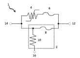
- FIG. 1 is a circuit diagram of one embodiment of the protection device of the present invention.
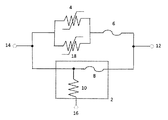
- FIG. 2 is a circuit diagram of another embodiment of the protection device of the present invention.
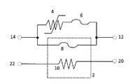
- FIG. 3 is a circuit diagram of still another aspect of the protection device of the present invention.
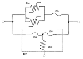
- FIG. 4 is a circuit diagram of the protection device of the present invention in the embodiment.
- FIG. 5 is a circuit diagram of a test circuit for a fusing test.
- FIG. 6 is a graph showing the voltage across the protection device and the circuit current in the fusing test.
- FIG. 1 shows a circuit diagram corresponding to one aspect of the protection device of the present invention.
- the protection device 1 of the present invention includes a protection element 2, a PTC element 4, and a second thermal fuse 6, and the PTC element 4 and the second thermal fuse 6 are electrically in series with each other.
- the protective element 2 is electrically connected in parallel to these.
- the protection element 2 is a portion surrounded by a dotted line in FIG. 1 and includes a first thermal fuse 8 and a resistor 10.
- the protection element 2 is operated by energizing the resistor 10 and operating the first thermal fuse 8 by heat generated by the resistor.
- the protection device 1 has terminals 12 and 14 for connection to an electric circuit or an electric device to be protected, and a terminal 16 for energizing the resistor 10.
- the current flows in the order of the terminal 12 ⁇ the first temperature fuse 8 ⁇ the terminal 14 (or its On the other hand, it does not substantially flow into the PTC element 4 and the second thermal fuse 6.
- the resistor 10 When an abnormality occurs, for example, when a short circuit, overcurrent, overvoltage, abnormal heat generation, or the like occurs in the electric circuit or device, the resistor 10 is energized from the terminal 16, thereby causing the resistor 10 to generate heat. Due to this heat, the first temperature fuse 8 operates (that is, the protection element 2 operates), whereby the current flowing through the first temperature fuse 8 is commutated to the PTC element 4, and the commutated current causes the PTC. The element 4 trips (operates). Then, the heat generated by the tripped PTC element 4 blows the second thermal fuse 6 to completely open the circuit and protect the electric circuit or the electric device.
- the resistor and the first thermal fuse are arranged to be thermally coupled. That is, the first thermal fuse is under the influence of heat of the resistor and operates by heat generated by the resistor.
- the number of the first thermal fuses to be installed is not particularly limited, and may be one or a plurality of, for example, two or three.
- the installation location of the first thermal fuse is electrically connected in series to the electrical circuit or electrical device to be protected, electrically connected in parallel to the PTC element and the second thermal fuse, and the heat of the resistor There is no particular limitation as long as it is placed under the influence, and it may be installed either upstream and / or downstream of the resistor.
- the resistor used in the protective element is not particularly limited as long as it is a resistor that can be used as a heating element.
- the first temperature fuse used for the protection element a material using a material generally used as a temperature fuse can be used.
- a low melting point metal such as solder (low (Including melting point alloys) can be used for the first thermal fuse.
- solder low (Including melting point alloys)
- Preferable low melting point metals are not particularly limited, and examples thereof include Sn-3.0Ag-0.5Cu and Sn-58Bi.
- a person skilled in the art can select an appropriate temperature fuse as the first temperature fuse so as to exhibit the intended function based on the contents of the present specification.
- the first temperature fuse may be operated by general fusing, that is, when the fuse element is melted and is attracted to the electrodes at both ends of the element by its surface tension and split, or a mechanical auxiliary mechanism
- the electrodes may be operated by physically separating the electrodes to which the fuse element is connected by using a spring, a magnet, etc., and ensuring an insulation distance.
- the protective element has a mechanism that mechanically assists the operation of the first thermal fuse.
- one of the electrodes of the first thermal fuse may be a movable electrode, the other may be a fixed electrode, or both may be movable electrodes.
- a fusing resistor is a temperature fuse with a resistor having a resistor and a low melting point metal (functioning as a temperature fuse) that melts by heat generated by energizing the resistor.
- it has a pair of lead fixed electrodes, a guide shaft is juxtaposed with these lead fixed electrodes, and a movable electrode is inserted over the guide shaft and is disposed across the lead fixed electrodes.
- a compression spring is provided between the distal end of the fixed electrode and the movable electrode and between the guide shaft and the movable electrode with a low melting point alloy and applies a force in a direction away from the lead fixed electrode to the movable electrode.
- a fusing resistor is used, wherein when the low melting point alloy is melted, the movable electrode is biased by a compression spring and separated from the lead fixed electrode.
- one lead conductor of a resistor having lead conductors attached to both ends of the resistor is used as a guide shaft, a coil spring is used as a compression spring, and the coil spring is connected to the resistor.
- a fusing resistor characterized in that a resistor energization heating circuit is connected between one lead conductor of a resistor and either one of the two lead fixed electrodes between the movable electrode and the one lead conductor. Is used.
- the PTC element used in the protective device of the present invention is not particularly limited, and a conventionally used PTC element, for example, a polymer PTC element or a ceramic PTC element can be used.
- a preferred PTC element is a polymer PTC element.
- the number of installed PTC elements is not particularly limited, and may be one or more, for example, two or three.
- the installation location of the PTC element is not particularly limited as long as it is electrically connected in series to the electrical circuit or device to be protected and the second temperature fuse and electrically connected in parallel to the first temperature fuse. .
- the polymer PTC element is formed by extruding a conductive composition containing a polymer (for example, polyethylene, polyvinylidene fluoride, etc.) in which a conductive filler (for example, carbon black, nickel alloy, etc.) is dispersed. And the electrode (for example, metal foil) arranged on both sides thereof.
- a conductive composition containing a polymer (for example, polyethylene, polyvinylidene fluoride, etc.) in which a conductive filler (for example, carbon black, nickel alloy, etc.) is dispersed.
- the electrode for example, metal foil
- other elements such as leads may be directly connected to the PTC element, in which case the electrode can be omitted.
- the PTC element has a resistance value equal to or lower than the rated voltage / abnormal current of the protective element at the operating temperature. That is, in this aspect, during the operation of the first temperature fuse, the current flowing through the first temperature fuse is commutated to the PTC element so that a voltage higher than the rated voltage is not applied to the protection element.
- R d is a combined resistance of the protection element (first temperature fuse), the PTC element, and the second temperature fuse.
- the resistance value of the PTC element By setting the resistance value of the PTC element to be equal to or lower than the rated voltage / abnormal current, the voltage applied to the protective element during operation can be reduced to the rated voltage or lower. That is, by reducing the resistance value of the PTC element as much as possible, the current that can be tolerated during an abnormality increases.
- said use temperature is the temperature of the environment where the protection device of this invention is used in a normal state, and is determined according to the use, installation place, etc. of a protection device.
- the use temperature is typically room temperature (about 20 to 25 ° C.), but is not limited thereto, for example, higher temperature, specifically about 25 to 100 ° C., for example about 30 to 60 ° C. It may be in the range.
- said abnormal current means the electric current value which flows through a protection device at the time of a short circuit, when abnormality arises, for example.
- the polymer PTC element has a resistance value equal to or lower than the rated voltage / abnormal current of the protective element at a temperature 10 ° C., preferably 5 ° C. lower than the softening point of the polymer material of the polymer PTC element.
- the softening point of the polymer material of the polymer PTC element can be obtained, for example, by measuring according to JIS K7206.
- the rate of increase in the resistance value of the PTC element increases rapidly.
- the slope of the tangent line of the resistance value-temperature curve is 5 times or more.
- the softening point of the polymer material of the polymer PTC element is set several tens of degrees Celsius higher than the use temperature. Therefore, the polymer PTC element has a resistance value equal to or lower than the rated voltage / abnormal current of the protective element at a temperature slightly lower than the softening point, for example, a temperature lower by 10 ° C., preferably 5 ° C. Even when the ambient temperature is equal to or higher than the assumed operating temperature, it is possible to suppress the occurrence of an arc during the operation of the first thermal fuse.
- the PTC element has an operating time longer than the insulation time of the first thermal fuse.
- the operation time of the PTC element refers to the voltage between both ends (electrodes) of the PTC element after the current that is commutated by the operation of the protection element is applied to the PTC element. Means the time to reach
- the insulation time of the first temperature fuse means the time from when the first temperature fuse is operated until the insulation is secured.
- the fuse element after fusing from the time when the fuse element starts fusing that is, from the time when the fuse element melts and becomes thin and its resistance value starts to rise.
- the time to solidify Means the time to solidify.
- the fuse element (low melting point metal) that connects the electrodes of the first thermal fuse melts and the insulation distance is reliably maintained after the electrodes start to separate. It means the time until it becomes ready.
- the operating time of the PTC element is preferably 30 milliseconds or more, and more preferably 40 milliseconds or more when the operation of the first thermal fuse is based on general fusing.
- the operation time of the PTC element is preferably 3 milliseconds or more, and more preferably 5 milliseconds or more, when the operation of the first temperature fuse is mechanically assisted.
- the fuse element In the first temperature fuse, the fuse element is melted by Joule heat generated by the resistor, the melted fuse element is blown, or is cut by a mechanical auxiliary mechanism, and the distance between the cut fuse elements (between electrodes) is Safely cuts off current by exceeding the insulation distance.
- An arc can occur when the distance between the melted or divided elements (between the electrodes) is less than the insulation distance, but when the distance exceeds the insulation distance, the arc is extinguished.
- the first thermal fuse is operated by general fusing, the element immediately after fusing is not completely solidified and has fluidity, so that the distance between the divided elements that are deformed and divided is less than the insulation distance. There is a case.
- the movable electrode vibrates for a certain period of time after the division, so the distance from the other electrode is not fixed and is less than the insulation distance There is. At this time, if the voltage applied to the protective element exceeds the rated voltage of the protective element, an arc is generated violently, causing a serious problem such as damaging the device to be protected. As described above, by making the operation time of the PTC element longer than the insulation time of the element of the first thermal fuse, the above problems can be avoided and the current can be cut off more safely. .
- the second thermal fuse used in the PTC device of the present invention is not particularly limited, and in addition to a commercially available thermal fuse, one generally used as a thermal fuse can be used.
- the number of second thermal fuses installed is not particularly limited, and may be one or more, for example, two or three.
- the installation location of the second thermal fuse is not particularly limited as long as it is under the thermal influence of the PTC element and is electrically connected in series to the electrical circuit or device to be protected and the PTC element.
- the second thermal fuse has an operating temperature that is lower than the trip temperature of the PTC element. Since the second temperature fuse has such an operating temperature, the second temperature fuse can be surely blown after the trip of the PTC element, and the circuit can be completely opened more reliably.
- the trip temperature of the PTC element means that the PTC element has tripped (operated) and is in a high temperature and high resistance state, specifically, the resistance value of the PTC element is 10 3 times or more than normal. Means the temperature.
- the second thermal fuse has a fusing time with an abnormal current longer than the trip time of the PTC element. Since the second temperature fuse has such a fusing time, the second temperature fuse can be blown after the PTC element trips, that is, after the current is significantly suppressed. It is possible to suppress the occurrence of arcs associated with.
- the trip time of the PTC element is specifically the PTC element from when the protective element is operated and the commutated current is applied to the PTC element until the PTC element is tripped to a high temperature / high resistance state. Means the time until the resistance value becomes 10 3 times or more of the normal value.
- the fusing time of the second temperature fuse is the time until the second temperature fuse is blown when this current continues to flow after the protective element is activated and the commutated current is supplied to the second temperature fuse. Means time.
- the second temperature fuse has a withstand voltage higher than an abnormal voltage in a leakage current when the PTC element is in a trip state. Even after a trip, the PTC element can pass a leakage current (micro current), for example, a current of about 30 mA. Since the second temperature fuse has a withstand voltage higher than an abnormal voltage (voltage applied to the circuit at the time of abnormality, for example, a short circuit) in such a leakage current, an arc is generated due to the melting of the second temperature fuse. Can be suppressed.
- the protection device of the present invention when the first temperature fuse of the protection element operates, a part of the current flowing through the first temperature fuse can be shunted to the circuit on the PTC element side, and an arc is generated during operation. Therefore, even if it is used for an electric circuit or an electric device in which a voltage exceeding the rated voltage of the protective element and / or a current exceeding the rated current flows, the current can be safely interrupted.
- FIG. 2 shows a circuit diagram of another aspect of the protection device of the present invention.
- the protection device of the present invention further includes another PTC element 18. That is, the protection device of the present invention in this embodiment includes two PTC elements. These PTC elements are electrically connected to each other in parallel and electrically connected to the second thermal fuse in series. Other configurations are substantially the same as those shown in FIG.
- PTC elements In FIG. 2, two PTC elements are used, but more PTC elements can also be used. These PTC elements are electrically connected to each other in parallel and electrically connected to the second thermal fuse in series.
- the “resistance value of the PTC element” is a combined resistance value of the plurality of PTC elements. Therefore, by using a plurality of PTC elements in parallel as described above, the “resistance value of the PTC element” can be further reduced, and the resistance value of the PTC element is set to be equal to or lower than the rated voltage / abnormal current of the protective element. Easy to do.
- FIG. 3 shows a circuit diagram of still another aspect of the protection device of the present invention.
- the resistor is incorporated in the same circuit as the first thermal fuse.
- the resistor is incorporated in another independent circuit.
- the protection device of the present invention has four terminals: terminal 12, terminal 14, terminal 20 and terminal 22.
- Other configurations are substantially the same as those shown in FIG.
- the present invention also provides an electric apparatus comprising the protection device of the present invention.
- protection device Fusing resistor (model number: BZ05, rated current: 75A; rated voltage: 60V) manufactured by Uchihashi Estec Co., Ltd. as protection element 102, polyswitch (registered trademark) manufactured by TE Connectivity as PTC element 104 ) (Model number: TRF600-400, resistance value: 1.2 ⁇ , softening point: 80 ° C.), and as the second thermal fuse 106, a thermo protector (model number: TR92; nominal operating temperature: manufactured by Uchihashi Estec Co., Ltd.) 115 ° C .; rated current: 9 A; rated voltage: 32 V), and connected so as to be the circuit diagram shown in FIG. 4 to produce the protection device of the present invention.
- a portion surrounded by a dotted line is a fusing resistor, and the fusing resistor includes a resistor 110 and a thermal fuse 108.
- the protection device normally cut off the current without any problems. Further, although not shown in FIG. 6, after about 4 seconds, the second temperature fuse was blown normally without any trouble and the circuit was completely opened.
- a voltage increase of about 10 V was recognized immediately after the fusing resistor thermal fuse was activated, but thereafter it was confirmed that the voltage increase was suppressed until about 10 milliseconds later. This is because the current flowing through the fusing resistor is commutated to the PTC element.
- the operating current is about 90A, which is higher than the rated current of the fusing resistor, but the operating voltage is 10V or less, which is much lower than the rated voltage. Can do.
Landscapes
- Physics & Mathematics (AREA)
- Thermal Sciences (AREA)
- Fuses (AREA)
- Engineering & Computer Science (AREA)
- Thermistors And Varistors (AREA)
- Microelectronics & Electronic Packaging (AREA)
- Power Engineering (AREA)
- Chemical & Material Sciences (AREA)
- Combustion & Propulsion (AREA)
- Ceramic Engineering (AREA)
- Electromagnetism (AREA)
- Emergency Protection Circuit Devices (AREA)
Abstract
Description
(ii)PTC素子と、
(iii)第2温度ヒューズ
とを含んで成り、
第2温度ヒューズが、PTC素子に対して電気的に直列に接続されており、
保護素子の第1温度ヒューズが、PTC素子および第2温度ヒューズに対して電気的に並列に接続されており、
異常時に、保護素子を動作させることによって、PTC素子がトリップして発熱し、この熱により第2温度ヒューズが溶断されること
を特徴とする保護デバイスを提供する。
Ed’≦Er ・・・(1)
[式中、Ed’=第1温度ヒューズの動作時(異常時)の保護デバイスの両端電圧、
Er=保護素子の定格電圧]
を満たせばよい。
Ed=Ic×Rd ・・・(2)
[式中、Ed=保護デバイスの両端電圧、
Ic=回路電流、
Rd=保護デバイス全体の抵抗]
となる。
Rd=1/(1/R1+1/(Rp+R2))
[式中、R1=保護素子(第1温度ヒューズ)の抵抗、
Rp=PTC素子の抵抗、
R2=第2温度ヒューズの抵抗]
となる。
Rd=1/(1/R1+1/Rp) ・・・(3)
となる。
Rd’=1/(1/Rp)=Rp ・・・(3’)
となる。
Ic’×Rp≦Er
変形して、
Rp≦Er/Ic’
[式中、Rp=PTC素子の抵抗、
Er=保護素子の定格電圧、
Ic’=異常電流]
となる。
・保護デバイスの作成
保護素子102として、内橋エステック株式会社製のヒュージングレジスタ(型番:BZ05、定格電流:75A;定格電圧:60V)、PTC素子104として、TE Connectivity 社製のポリスイッチ(登録商標)(型番:TRF600-400、抵抗値:1.2Ω、軟化点:80℃)を2つ、および第2温度ヒューズ106として、内橋エステック株式会社製のサーモプロテクタ(型番:TR92;公称動作温度:115℃;定格電流:9A;定格電圧:32V)を使用して、図4に示す回路図となるように接続して、本発明の保護デバイスを作製した。なお、図4において点線によって包囲した部分がヒュージングレジスタであり、ヒュージングレジスタは、抵抗体110と温度ヒューズ108を含む。
作製した保護デバイス101を用いて、図5に示す回路にて遮断試験を行った。用いた機器は下記表1に示す。なお、内側の破線によって包囲した部分がヒュージングレジスタであり、外側の破線によって包囲した部分が保護デバイスである。室温で、パワーライン直流電源112により、回路に100A-500Vの電流を流した状態で、信号ライン直流電源118からヒュージングレジスタの抵抗体に通電し、ヒュージングレジスタの温度ヒューズを動作させた。保護デバイスの両端電圧と、回路電流を測定した。結果を図6に示す(ヒュージングレジスタの温度ヒューズの動作時を0秒とする)。

ヒュージングレジスタの定格電流(75A)および定格電圧(60V)を大きく超える電流および電圧であったにもかかわらず、保護デバイスは、不具合無く、正常に電流を遮断した。また、図6には示していないが、約4秒後に、第2温度ヒューズも不具合なく、正常に溶断し、回路は完全に開かれた状態となった。
6…第2温度ヒューズ;8…第1温度ヒューズ;10…抵抗体;
12…端子;14…端子;16…端子;18…PTC素子;
20…端子;22…端子;101…保護デバイス;102…保護素子;
104…PTC素子;106…第2温度ヒューズ;
108…第1温度ヒューズ;110…抵抗体;
112…パワーライン直流電源;114…パワーライン負荷;
116…スイッチ;118…信号ライン直流電源;120…スイッチ
Claims (14)
- (i)第1温度ヒューズと抵抗体とを含んで成り、異常時に抵抗体に通電することによって抵抗体が発熱し、この熱により第1温度ヒューズが動作して、電流を遮断する保護素子と、
(ii)PTC素子と、
(iii)第2温度ヒューズ
とを含んで成り、
第2温度ヒューズが、PTC素子に対して電気的に直列に接続されており、
保護素子の第1温度ヒューズが、PTC素子および第2温度ヒューズに対して電気的に並列に接続されており、
異常時に、保護素子を動作させることによって、PTC素子がトリップして発熱し、この熱により第2温度ヒューズが溶断されること
を特徴とする保護デバイス。 - 保護素子がヒュージングレジスタであることを特徴とする、請求項1記載の保護デバイス。
- ヒュージングレジスタが、一対のリード固定電極を有し、これらのリード固定電極にガイド軸が並設され、可動電極がガイド軸に挿通された状態で前記リード固定電極間にまたがって配設され、各リード固定電極の先端と可動電極との間および前記ガイド軸と可動電極との間が低融点合金で接合され、前記可動電極に前記リード固定電極より離隔させる方向の力を作用させる圧縮バネが設けられ、前記低融点合金の溶融で可動電極が圧縮バネで付勢されて前記リード固定電極より離隔されることを特徴とする、請求項2記載の保護デバイス。
- ヒュージングレジスタにおいて、抵抗体の両端にリード導体が取付けられてなる抵抗器の一方のリード導体がガイド軸として使用され、圧縮バネにコイルバネが使用され、該コイルバネが抵抗体と可動電極との間において前記一方のリード導体に挿通され、抵抗器の一方のリード導体と両リード固定電極の何れかとの間に抵抗器通電発熱回路が接続されることを特徴とする、請求項3記載の保護デバイス。
- PTC素子が、ポリマーPTC素子であることを特徴とする、請求項1~4のいずれかに記載の保護デバイス。
- 使用温度でのPTC素子の抵抗値が、保護素子の定格電圧/異常電流以下であることを特徴とする、請求項1~5のいずれかに記載の保護デバイス。
- ポリマーPTC素子のポリマー材料の軟化点より10℃低い温度でのPTC素子の抵抗値が、保護素子の定格電圧/異常電流以下であることを特徴とする、請求項5に記載の保護デバイス。
- PTC素子の動作時間が、第1温度ヒューズのヒューズエレメントの絶縁時間よりも長いことを特徴とする、請求項1~7のいずれかに記載の保護デバイス。
- PTC素子の動作時間が、3ミリ秒以上であることを特徴とする、請求項1~8のいずれかに記載の保護デバイス。
- 前記PTC素子に電気的に並列に接続され、かつ、第2温度ヒューズに電気的に直列に接続されている1つまたはそれ以上の別のPTC素子を含むことを特徴とする、請求項1~9のいずれかに記載の保護デバイス。
- 第2温度ヒューズの動作温度が、PTC素子のトリップ温度よりも低いことを特徴とする、請求項1~10のいずれかに記載の保護デバイス。
- 異常電流での第2温度ヒューズの溶断時間が、PTC素子のトリップ時間よりも長いことを特徴とする、請求項1~11のいずれかに記載の保護デバイス。
- 第2温度ヒューズは、PTC素子がトリップ状態にある場合のリーク電流において、異常電圧以上の耐電圧性を有することを特徴とする、請求項1~12のいずれかに記載の保護デバイス。
- 請求項1~13のいずれかに記載の保護デバイスを有する電気装置。
Priority Applications (4)
| Application Number | Priority Date | Filing Date | Title |
|---|---|---|---|
| US14/901,987 US10483061B2 (en) | 2013-07-02 | 2014-07-01 | Protective device |
| KR1020167002333A KR20160029082A (ko) | 2013-07-02 | 2014-07-01 | 보호 디바이스 |
| CN201480043778.9A CN105684120B (zh) | 2013-07-02 | 2014-07-01 | 保护器件 |
| JP2015525232A JP6313301B2 (ja) | 2013-07-02 | 2014-07-01 | 保護デバイス |
Applications Claiming Priority (2)
| Application Number | Priority Date | Filing Date | Title |
|---|---|---|---|
| JP2013138958 | 2013-07-02 | ||
| JP2013-138958 | 2013-07-02 |
Publications (1)
| Publication Number | Publication Date |
|---|---|
| WO2015002187A1 true WO2015002187A1 (ja) | 2015-01-08 |
Family
ID=52143759
Family Applications (1)
| Application Number | Title | Priority Date | Filing Date |
|---|---|---|---|
| PCT/JP2014/067516 Ceased WO2015002187A1 (ja) | 2013-07-02 | 2014-07-01 | 保護デバイス |
Country Status (6)
| Country | Link |
|---|---|
| US (1) | US10483061B2 (ja) |
| JP (1) | JP6313301B2 (ja) |
| KR (1) | KR20160029082A (ja) |
| CN (1) | CN105684120B (ja) |
| TW (1) | TWI625754B (ja) |
| WO (1) | WO2015002187A1 (ja) |
Cited By (5)
| Publication number | Priority date | Publication date | Assignee | Title |
|---|---|---|---|---|
| WO2015133538A1 (ja) * | 2014-03-07 | 2015-09-11 | タイコエレクトロニクスジャパン合同会社 | 保護デバイス |
| CN105529216A (zh) * | 2016-01-28 | 2016-04-27 | 苏州工业园区凯恩电子科技有限公司 | 断电复位热保护器 |
| WO2018146942A1 (ja) * | 2017-02-13 | 2018-08-16 | ソニー株式会社 | アーク抑制装置 |
| CN113811974A (zh) * | 2019-05-09 | 2021-12-17 | 力特保险丝公司 | 具备ptc元件及二次熔断器的电路保护装置 |
| CN114730679A (zh) * | 2019-11-21 | 2022-07-08 | 力特保险丝公司 | 具有正温度系数装置和备用熔断器的电路保护装置 |
Families Citing this family (11)
| Publication number | Priority date | Publication date | Assignee | Title |
|---|---|---|---|---|
| KR20170116472A (ko) | 2016-04-11 | 2017-10-19 | 주식회사 엘지화학 | 검전기 및 시그널 퓨즈를 이용한 모스펫 릴레이 보호 장치 및 보호 방법 |
| JP7010706B2 (ja) * | 2018-01-10 | 2022-01-26 | デクセリアルズ株式会社 | ヒューズ素子 |
| EP3783634B1 (en) * | 2018-04-19 | 2025-05-14 | Mitsubishi Electric Corporation | Dc circuit breaker |
| DE102018118247B3 (de) * | 2018-07-17 | 2019-09-19 | Borgwarner Ludwigsburg Gmbh | Thermische Sicherung |
| CN209993563U (zh) * | 2019-01-16 | 2020-01-24 | 厦门赛尔特电子有限公司 | 一种高压熔断装置 |
| TWI811301B (zh) * | 2019-02-13 | 2023-08-11 | 南韓商Lg新能源股份有限公司 | 電池模組 |
| US11509159B2 (en) * | 2019-08-28 | 2022-11-22 | Microsoft Technology Licensing, Llc | System and method for thermal cutoff protection device control from an external component |
| JP7377069B2 (ja) * | 2019-11-08 | 2023-11-09 | デクセリアルズ株式会社 | 保護回路、バッテリパック及び保護回路の動作方法 |
| CN116802959A (zh) * | 2021-08-10 | 2023-09-22 | 深圳市华思旭科技有限公司 | 输出控制电路、启动电源和电瓶夹 |
| US12462957B2 (en) * | 2022-02-02 | 2025-11-04 | Littelfuse, Inc. | Thermal protection device to withstand high voltage |
| US12136810B2 (en) | 2022-10-03 | 2024-11-05 | Thomas Victorin | Start-up protection using inrush current control |
Citations (2)
| Publication number | Priority date | Publication date | Assignee | Title |
|---|---|---|---|---|
| JP2002233048A (ja) * | 2001-02-06 | 2002-08-16 | Sony Chem Corp | 保護回路付き二次電池 |
| JP2012521635A (ja) * | 2009-03-24 | 2012-09-13 | タイコ・エレクトロニクス・コーポレイション | リフロー可能な温度ヒューズ |
Family Cites Families (8)
| Publication number | Priority date | Publication date | Assignee | Title |
|---|---|---|---|---|
| US5737160A (en) * | 1995-09-14 | 1998-04-07 | Raychem Corporation | Electrical switches comprising arrangement of mechanical switches and PCT device |
| US5864458A (en) * | 1995-09-14 | 1999-01-26 | Raychem Corporation | Overcurrent protection circuits comprising combinations of PTC devices and switches |
| JP2000067710A (ja) * | 1998-08-20 | 2000-03-03 | Daito Tsushinki Kk | 遮断器 |
| JP2000306477A (ja) * | 1999-04-16 | 2000-11-02 | Sony Chem Corp | 保護素子 |
| EP2133973B1 (en) * | 2007-03-16 | 2015-05-06 | Tyco Electronics Raychem K.K. | Circuit protection device |
| JP4630403B2 (ja) * | 2008-01-21 | 2011-02-09 | 内橋エステック株式会社 | 保護素子 |
| JP5174893B2 (ja) * | 2008-04-10 | 2013-04-03 | ウチヤ・サーモスタット株式会社 | 外部操作型サーマルプロテクタ |
| WO2013099678A1 (ja) * | 2011-12-27 | 2013-07-04 | タイコエレクトロニクスジャパン合同会社 | 保護デバイス |
-
2014
- 2014-07-01 WO PCT/JP2014/067516 patent/WO2015002187A1/ja not_active Ceased
- 2014-07-01 JP JP2015525232A patent/JP6313301B2/ja active Active
- 2014-07-01 KR KR1020167002333A patent/KR20160029082A/ko not_active Withdrawn
- 2014-07-01 TW TW103122628A patent/TWI625754B/zh active
- 2014-07-01 US US14/901,987 patent/US10483061B2/en active Active
- 2014-07-01 CN CN201480043778.9A patent/CN105684120B/zh active Active
Patent Citations (2)
| Publication number | Priority date | Publication date | Assignee | Title |
|---|---|---|---|---|
| JP2002233048A (ja) * | 2001-02-06 | 2002-08-16 | Sony Chem Corp | 保護回路付き二次電池 |
| JP2012521635A (ja) * | 2009-03-24 | 2012-09-13 | タイコ・エレクトロニクス・コーポレイション | リフロー可能な温度ヒューズ |
Cited By (9)
| Publication number | Priority date | Publication date | Assignee | Title |
|---|---|---|---|---|
| WO2015133538A1 (ja) * | 2014-03-07 | 2015-09-11 | タイコエレクトロニクスジャパン合同会社 | 保護デバイス |
| JPWO2015133538A1 (ja) * | 2014-03-07 | 2017-04-06 | Littelfuseジャパン合同会社 | 保護デバイス |
| US10395877B2 (en) | 2014-03-07 | 2019-08-27 | Littelfuse, Inc. | Protective device |
| CN105529216A (zh) * | 2016-01-28 | 2016-04-27 | 苏州工业园区凯恩电子科技有限公司 | 断电复位热保护器 |
| WO2018146942A1 (ja) * | 2017-02-13 | 2018-08-16 | ソニー株式会社 | アーク抑制装置 |
| JPWO2018146942A1 (ja) * | 2017-02-13 | 2019-12-12 | ソニー株式会社 | アーク抑制装置 |
| JP7010245B2 (ja) | 2017-02-13 | 2022-01-26 | ソニーグループ株式会社 | アーク抑制装置 |
| CN113811974A (zh) * | 2019-05-09 | 2021-12-17 | 力特保险丝公司 | 具备ptc元件及二次熔断器的电路保护装置 |
| CN114730679A (zh) * | 2019-11-21 | 2022-07-08 | 力特保险丝公司 | 具有正温度系数装置和备用熔断器的电路保护装置 |
Also Published As
| Publication number | Publication date |
|---|---|
| TWI625754B (zh) | 2018-06-01 |
| US20180040443A1 (en) | 2018-02-08 |
| JP6313301B2 (ja) | 2018-04-18 |
| KR20160029082A (ko) | 2016-03-14 |
| JPWO2015002187A1 (ja) | 2017-02-23 |
| CN105684120A (zh) | 2016-06-15 |
| US10483061B2 (en) | 2019-11-19 |
| CN105684120B (zh) | 2018-04-13 |
| TW201508799A (zh) | 2015-03-01 |
Similar Documents
| Publication | Publication Date | Title |
|---|---|---|
| JP6313301B2 (ja) | 保護デバイス | |
| JP6357221B2 (ja) | 保護デバイス | |
| KR101116087B1 (ko) | 보호 장치 | |
| US6445276B2 (en) | Electrical fuse for use in motor vehicles | |
| JP6490583B2 (ja) | 保護デバイス | |
| CN110086144B (zh) | 保护装置 | |
| CN103748651B (zh) | 熔断器 | |
| JP2014007134A (ja) | 高遮断容量ヒューズ | |
| JP5752354B2 (ja) | 回路保護デバイス | |
| CN106716591A (zh) | 一种用于被保护装置的熔断器 | |
| KR20080041636A (ko) | 전기 복합 소자 | |
| JP6247002B2 (ja) | 接触器の中に組込可能な、交流電流が供給される電気回路を保護するための装置 | |
| JP4943359B2 (ja) | 保護素子 | |
| EP2587604A1 (en) | A fault protection device | |
| JP4905947B2 (ja) | 保護装置 | |
| JP3088588U (ja) | ヒューズ複合型バリスタ | |
| KR200267634Y1 (ko) | 열형 컷오프 배리스터 |
Legal Events
| Date | Code | Title | Description |
|---|---|---|---|
| 121 | Ep: the epo has been informed by wipo that ep was designated in this application |
Ref document number: 14820619 Country of ref document: EP Kind code of ref document: A1 |
|
| ENP | Entry into the national phase |
Ref document number: 2015525232 Country of ref document: JP Kind code of ref document: A |
|
| NENP | Non-entry into the national phase |
Ref country code: DE |
|
| ENP | Entry into the national phase |
Ref document number: 20167002333 Country of ref document: KR Kind code of ref document: A |
|
| 122 | Ep: pct application non-entry in european phase |
Ref document number: 14820619 Country of ref document: EP Kind code of ref document: A1 |
|
| WWE | Wipo information: entry into national phase |
Ref document number: 14901987 Country of ref document: US |