WO2015001696A1 - Dispositif d'antenne - Google Patents
Dispositif d'antenne Download PDFInfo
- Publication number
- WO2015001696A1 WO2015001696A1 PCT/JP2014/002384 JP2014002384W WO2015001696A1 WO 2015001696 A1 WO2015001696 A1 WO 2015001696A1 JP 2014002384 W JP2014002384 W JP 2014002384W WO 2015001696 A1 WO2015001696 A1 WO 2015001696A1
- Authority
- WO
- WIPO (PCT)
- Prior art keywords
- antenna
- antenna device
- antenna element
- cable
- coaxial cable
- Prior art date
Links
Images


Classifications
-
- H—ELECTRICITY
- H01—ELECTRIC ELEMENTS
- H01Q—ANTENNAS, i.e. RADIO AERIALS
- H01Q1/00—Details of, or arrangements associated with, antennas
- H01Q1/08—Means for collapsing antennas or parts thereof
- H01Q1/084—Pivotable antennas
-
- H—ELECTRICITY
- H01—ELECTRIC ELEMENTS
- H01Q—ANTENNAS, i.e. RADIO AERIALS
- H01Q1/00—Details of, or arrangements associated with, antennas
- H01Q1/27—Adaptation for use in or on movable bodies
- H01Q1/32—Adaptation for use in or on road or rail vehicles
- H01Q1/325—Adaptation for use in or on road or rail vehicles characterised by the location of the antenna on the vehicle
- H01Q1/3291—Adaptation for use in or on road or rail vehicles characterised by the location of the antenna on the vehicle mounted in or on other locations inside the vehicle or vehicle body
-
- H—ELECTRICITY
- H01—ELECTRIC ELEMENTS
- H01Q—ANTENNAS, i.e. RADIO AERIALS
- H01Q1/00—Details of, or arrangements associated with, antennas
- H01Q1/48—Earthing means; Earth screens; Counterpoises
-
- H—ELECTRICITY
- H01—ELECTRIC ELEMENTS
- H01Q—ANTENNAS, i.e. RADIO AERIALS
- H01Q21/00—Antenna arrays or systems
- H01Q21/28—Combinations of substantially independent non-interacting antenna units or systems
-
- H—ELECTRICITY
- H01—ELECTRIC ELEMENTS
- H01Q—ANTENNAS, i.e. RADIO AERIALS
- H01Q7/00—Loop antennas with a substantially uniform current distribution around the loop and having a directional radiation pattern in a plane perpendicular to the plane of the loop
- H01Q7/06—Loop antennas with a substantially uniform current distribution around the loop and having a directional radiation pattern in a plane perpendicular to the plane of the loop with core of ferromagnetic material
- H01Q7/08—Ferrite rod or like elongated core
-
- H—ELECTRICITY
- H01—ELECTRIC ELEMENTS
- H01Q—ANTENNAS, i.e. RADIO AERIALS
- H01Q9/00—Electrically-short antennas having dimensions not more than twice the operating wavelength and consisting of conductive active radiating elements
- H01Q9/04—Resonant antennas
- H01Q9/16—Resonant antennas with feed intermediate between the extremities of the antenna, e.g. centre-fed dipole
- H01Q9/20—Two collinear substantially straight active elements; Substantially straight single active elements
- H01Q9/22—Rigid rod or equivalent tubular element or elements
-
- H—ELECTRICITY
- H01—ELECTRIC ELEMENTS
- H01Q—ANTENNAS, i.e. RADIO AERIALS
- H01Q9/00—Electrically-short antennas having dimensions not more than twice the operating wavelength and consisting of conductive active radiating elements
- H01Q9/04—Resonant antennas
- H01Q9/30—Resonant antennas with feed to end of elongated active element, e.g. unipole
Definitions
- the present disclosure relates to an antenna device applicable to, for example, a vehicle-mounted antenna.
- a film antenna that can be attached to a windshield or rear glass has been proposed as a car navigation device installed in a vehicle or a PND (Personal Navigation Device) antenna attached to the vehicle (see, for example, Patent Document 1 below).
- the film antenna has a problem that the gain is lower than that of the rod antenna because a material having a sufficiently high conductivity is not used and the length of the antenna cable is long. Therefore, there is a problem that it is necessary to use an amplifier.
- one of the objects of the present disclosure is to provide an antenna device that can perform diversity reception and solve the above problem.
- the present disclosure includes a first and a second antenna element that receives at least one of a broadcast wave and a signal that is superimposed and transmitted on the broadcast wave;
- a ground element that functions as a common ground for the first and second antenna elements;
- This is an antenna device in which the mounting angle of at least one of the first antenna element and the second antenna element can be adjusted.
- Diversity reception can be performed by the first antenna element and the second antenna element. Furthermore, according to at least one embodiment, an antenna device that is excellent in reception performance and easy to install is provided. Furthermore, when the ground element is provided, the ground element and the metal part of the vehicle body are electrostatically coupled when used as an in-vehicle antenna. As a result, the area of the portion functioning as the ground is increased, so that the reception characteristics of the antenna can be improved. Note that the effects described here are not necessarily limited, and may be any effects described in the present disclosure. Further, the contents of the present disclosure are not construed as being limited by the exemplified effects.
- A is a figure for demonstrating an example of the structure of the rod antenna element in one Embodiment
- B is a figure for demonstrating an example of the protrusion formed in the said rod antenna element.
- a and B are figures for demonstrating the jack in which the plug of the rod antenna element in one Embodiment is inserted.
- It is a figure for demonstrating an example of the structure of the coaxial cable in one Embodiment.
- It is a figure for demonstrating the other example of the structure of the coaxial cable in one Embodiment.
- FIG. 4A is a diagram illustrating an example of a C / N ratio of a signal received by a wire antenna element according to an embodiment
- B is an example of a C / N ratio of a signal received by a rod antenna element according to an embodiment.
- FIG. It is a figure for demonstrating the example of arrangement
- A is a graph showing an example of frequency-gain characteristics in the UHF band of a wire antenna element in one embodiment
- B is a graph of gain characteristics when each of vertical polarization and horizontal polarization is received by the wire antenna element. It is a table
- A is a graph showing an example of frequency-gain characteristics in the UHF band of a rod antenna element in one embodiment, and B is a graph of gain characteristics when each of vertical polarization and horizontal polarization is received by the rod antenna element. It is a table
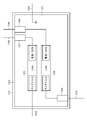
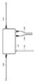
- FIG. 1 shows an example of the configuration of an antenna device 10 according to an embodiment.
- the antenna device 10 in one embodiment is installed in a vehicle as an example.
- the antenna device 10 receives at least one of a broadcast wave and a signal transmitted by being superimposed on the broadcast wave.
- the broadcast wave is, for example, terrestrial digital broadcast using a UHF band frequency
- the signal transmitted by being superimposed on the broadcast wave is, for example, data broadcast.
- the antenna device 10 includes, for example, a case 101 formed by molding synthetic resin, an antenna element 102, an antenna element 103, a ground element 104, and two coaxial cables (coaxial cable 105 and coaxial cable 106). .
- the antenna element 102 which is an example of the first antenna element is configured as a wire antenna element using a coaxial cable, for example.
- the antenna element 103 which is an example of the second antenna element is configured as a rod-shaped rod antenna element.
- both antenna elements may be constituted by wire antenna elements or rod antenna elements.
- the antenna element 102 is appropriately referred to as a wire antenna element 102
- the antenna element 103 is appropriately referred to as a rod antenna element 103.
- Case 101 a wiring board as an example of a power feeding unit is accommodated.
- a heat resistant ABS resin is used as a material of the case 101.
- Case 101 has a main surface 112, a back surface 113 opposite to the main surface, and four side surfaces (a side surface 114, a side surface 115, a side surface 116, and a side surface 117).
- the wire antenna element 102, the rod antenna element 103, the ground element 104, the coaxial cable 105, and the coaxial cable 106 are connected to the case 101.
- the wire antenna element 102 is connected to the side surface 115
- the rod antenna element 103 is connected to the side surface 114.
- the ground element 104 is connected to the side surface 117
- the coaxial cable 105 and the coaxial cable 106 are connected to the side surface 116.
- the rod antenna element 103 is detachable from the case 101.
- the wire antenna element 102 may be detachable from the case 101.
- the wire antenna element 102 and the rod antenna element 103 constitute an antenna.
- a desired frequency can be received by the antenna device 10 by setting the total length obtained by adding the length of the wire antenna element 102 and the length of the rod antenna element 103 to about ⁇ / 2 of the frequency to be received.
- the length of the wire antenna element 102 is set to 12 cm (centimeter), for example, and the length of the rod antenna element 103 is set to 10 cm, for example.
- the ground element 104 is constituted by a coaxial cable, for example.
- the length of the ground element 104 is set to 11 cm, for example.
- the wire antenna element 102 and the ground element 104 described above are connected to a substrate housed in the case 101 by soldering or the like.
- the ground element 104 is bent in a predetermined direction, and is installed, for example, in the vicinity of a metal part of the vehicle body.
- a round plug is attached to the tip of the coaxial cable 105.
- an audio plug 110 having a diameter of 3.5 mm (millimeters) is attached.
- a three-pole audio plug 111 having a diameter of 3.5 mm is attached to the tip of the coaxial cable 106, for example.
- the audio plug 110 and the audio plug 111 are connected to, for example, a PND (not shown).
- the coaxial cable 105 and the coaxial cable 106 may be configured as so-called glasses cables in which both cables are integrally formed. Moreover, the coaxial cable 105 and the coaxial cable 106 may be inserted in the ferrite core for noise countermeasures. In this case, the number of turns of the cable (number of turns) can be set as appropriate.
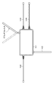
- FIG. 2 shows an example of the configuration inside the case 101.
- a wiring board 120 is housed inside the case 101.
- a ground conductor (ground conductor) 121 is formed directly or via an insulating film.
- the ground conductor 121 is also formed on the back surface of the wiring board 120, and is connected to the ground conductor 121 on the upper surface through a normal through-hole or the like so as to function as a ground.
- the ground element 104 is connected to the ground conductor 121, and the ground element 104 functions as a common ground for the wire antenna element 102 and the rod antenna element 103.
- connection part 127, the connection part 128, and the connection part 129 are formed in the wiring board 120.
- the connecting portion 127 includes a plug formed at the tip of the coaxial cable 105 and a jack into which the plug is inserted.
- the connecting portion 128 includes a plug formed at the tip of the coaxial cable 106 and a jack into which the plug is inserted.
- a two-pole plug is formed at each end of the coaxial cable 105 and the coaxial cable 106.
- the jack into which the plug is inserted has a configuration corresponding to the plug, for example, a three-pole jack.
- the connecting portion 129 includes, for example, a plug formed at the tip of the rod antenna element 103 and a jack into which the plug is inserted.
- a plug formed at the tip of the rod antenna element 103 and a jack into which the plug is inserted.
- a three-pole plug is formed at the tip of the rod antenna element 103.
- the jack into which the plug is inserted has a configuration corresponding to the plug, for example, a three-pole jack.
- the wiring board 120 is provided with an LNA (Low Noise Amplifier) 125 and an LNA 126.
- the LNA 125 and the LNA 126 are for improving the S / N ratio (Signal to Noise Ratio) of the received signal before demodulation, and are configured by appropriately combining circuit elements such as resistors, coils, and transistors, for example. .
- the wire antenna element 102 is connected to the input part (antenna input) of the LNA 125.
- the output unit (power supply / output) of the LNA 125 and the connection unit 127 are connected, and the power for operating the LNA 125 is supplied from the PND to which the coaxial cable 105 is connected to the LNA 125.
- the antenna signal received by the wire antenna element 102 and amplified by the LNA 125 is configured to be supplied to the PND via the coaxial cable 105.
- the antenna signal is superimposed on the power supply voltage.
- connection unit 129 is connected to the input unit (antenna input) of the LNA 126.
- the output unit (power supply / output) of the LNA 126 and the connection unit 129 are connected, and the power for operating the LNA 126 is supplied from the PND to which the coaxial cable 106 is connected to the LNA 126.
- the antenna signal received by the rod antenna element 103 and amplified by the LNA 126 is configured to be supplied to the PND via the coaxial cable 106. The antenna signal is superimposed on the power supply voltage.
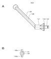
- FIG. 3A is a side view of the rod antenna element 103.
- the rod antenna element 103 includes, for example, an antenna unit 130 and a support unit 131 that supports the antenna unit 130.
- the support part 131 has a cylindrical shape, for example, and the antenna part 130 is connected to one end surface side of the support part 131.
- the antenna unit 130 is bent and attached to the support unit 131 at a predetermined angle (for example, about 45 to 60 degrees).
- the wire part 135 which consists of a polyurethane wire (UEW line) or a coaxial line has penetrated the antenna part 130 and the support part 131 inside.
- the antenna portion 130 and the support portion 131 are formed by molding the periphery of the wire 135 with, for example, resin.
- resin heat-resistant PVC (Poly-Vinyl-Chloride) material, heat-resistant PP material (Poly-Propylene), or the like is used.
- a plug 132 made of an audio plug with a diameter of 3.5 mm is attached to the other end surface (the other end surface) of the support portion 131.
- a hook-shaped protrusion 133 is formed near the other end surface of the support portion 131.
- the protrusion 133 includes, for example, a protrusion 133a and a protrusion 133b.
- a jack 140 for attaching the rod antenna element 103 is formed on the side surface 114 of the case 101.
- FIG. 4B shows an example of the configuration of the jack 140.
- the jack 140 has a positioning groove 141 including a groove part 141a and a groove part 141b.
- the rod antenna element 103 can be attached to the case 101 with a predetermined positional relationship by inserting the protrusion 133 into the positioning groove 141.
- the mounting angle of the rod antenna element 103 can be adjusted according to the insertion position of the protrusion 133 into the positioning groove 141. For example, when the protrusion 133a is inserted into the groove 141a and the protrusion 133b is inserted into the groove 141b, and when the protrusion 133a is inserted into the groove 141b and the protrusion 133b is inserted into the groove 141a, the rod antenna element 103 The mounting angle can be different.
- the structure which can connect the antenna part 130 and the support part 131 via a rotation mechanism, and can rotate the antenna part 130 at an angle of about 180 degree
- the mounting angle of the rod antenna element 103 may be adjusted by rotating the antenna unit 130.
- the rod antenna element 103 having the bent antenna portion 130 is detachable from the case 101. If the rod antenna element 103 is removed from the case 101, the overall size of the antenna device 10 can be reduced, and the antenna device 10 can be easily packed in a predetermined box or the like.
- Example of coaxial cable configuration An example of the configuration of the coaxial cable 105 in one embodiment will be described. The configuration of the coaxial cable 106 is the same.
- FIG. 5 shows a cross section of an example of the coaxial cable 105.
- An outside of an annealed copper wire 151 which is an example of an internal conductor is covered with an insulator 152 such as polyethylene, and a braided wire 153 is formed on the outside thereof.
- an insulator 152 such as polyethylene
- a braided wire 153 is formed on the outside thereof.
- a layer of ferrite material (suitably abbreviated as ferrite material) 154 mainly for preventing noise from the PND is formed on the outside of the braided wire 153.
- the outer side of the ferrite material 154 is covered with an outer skin 155.
- FIG. 6 and 7 show cross sections of other examples of the coaxial cable 105.
- FIG. A shielding material may be provided in order to improve the shielding performance against noise.
- a single-sided aluminum foil tape 156 may be provided between the insulator 152 and the braided wire 153.
- the single-sided aluminum foil tape 156 is attached so that the inner surface (surface on the insulator 152 side) is insulating tape and the outer surface (surface on the braided wire 153 side) is aluminum.
- the single-sided aluminum foil tape 156 may be provided between the braided wire 153 and the ferrite material 154.
- the shield material is not limited to aluminum foil, but may be copper foil.
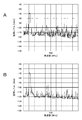
- FIG. 8A is a graph showing a C / N ratio (Carrier to Noise) of a received signal when a normal coaxial cable is used
- FIG. 8B is a graph of C of the received signal when a coaxial cable including a ferrite material is used. It is a graph which shows / N ratio. 8A and 8B, the horizontal axis indicates the frequency (MHz), and the vertical axis indicates the signal level (dBm).
- the C / N ratio is indicated by the interval between the signal level and the noise floor level in the graph.
- the noise floor level in FIG. 8B is lower than the noise floor level in FIG. 8A. That is, the coaxial cable using the ferrite material has a higher C / N ratio than the normal coaxial cable, and the received signal quality is better. This is considered because the ferrite in the coaxial cable suppresses that the output cable receives noise radiated from the PND and the C / N ratio deteriorates. From the above, it is preferable to use a ferrite material for the coaxial cable.
- Example of antenna device arrangement For example, two antenna devices 10 are used to perform 4 diversity reception. 4 diversity reception is used when receiving a broadcast using a high-order modulation method such as a full segment broadcast.
- FIG. 9 is a diagram illustrating an example of attachment of the antenna device 10 to a vehicle.
- the example shown in FIG. 9 is an example in which two antenna devices 10 are respectively installed at substantially symmetrical positions (right end and left end) of the dashboard 162 in contact with the lower side of the windshield 161 of the car.
- the antenna device 10 installed at the right end is installed on the dashboard 162 with the main surface 112 facing upward.
- the antenna device 10 installed at the left end is installed on the dashboard 162 with the back surface 113 facing upward.
- the antenna device 10 is configured to be used as either the left or right antenna device 10 only by reversing the main surface 112 of the case 101.
- the wire antenna element 102 is mounted on the dashboard 162 so as to be substantially parallel to the lower side of the windshield 161.
- the wire antenna element 102 is attached to the dashboard 162 using a clamper, an adhesive, a tape, or the like.
- the rod antenna element 103 is positioned in the height direction with respect to the dashboard 162.
- the ground element 104 is disposed and attached along the right side or the left side of the windshield 161.
- metal bodies hereinafter referred to as pillars as appropriate
- the tip of the coaxial cable 105 (audio plug 110) and the tip of the coaxial cable 106 (audio plug 111) are connected to the PND 165.
- a receiver (not shown) is built in the PND 165, and this receiver performs diversity reception and demodulates the received signal. In one embodiment, a spatial diversity maximum ratio combining method is used as an example of diversity reception.
- the signal demodulated by the receiver is supplied to the display 166 and the like, and video and audio are reproduced.
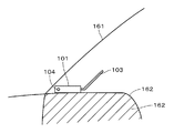
- FIG. 10 is a view of the antenna device 10 disposed at the left end of the dashboard 162 as viewed from the left side surface.
- the case 101 of the antenna device 10 is attached to the dashboard 162.
- the case 101 is attached to the dashboard 162 with an adhesive tape, a suction cup, or the like.
- the antenna portion 130 of the rod antenna element 103 is attached to the support portion 131 so as to form an angle of about 45 degrees instead of a right angle. For this reason, the antenna device 10 can be installed on the back side of the dashboard 162 without bringing the rod antenna element 103 into contact with the windshield 161.
- a mark may be attached to the surface of the case 101. For example, arrows directed in the same direction may be attached to the main surface 112 and the back surface 113 of the case 101. The user should just install the antenna apparatus 10 so that the direction of the arrow may coincide with the traveling direction of the car.
- the ground element 104 By disposing the ground element 104 on the pillar or close to the pillar, the ground element 104 and the pillar are capacitively coupled, and the ground of the antenna is widened. As a result, the level of the reception signal received by the antenna device 10 is improved, and further, the reception characteristics during traveling are also improved.
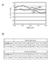
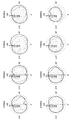
- FIG. 11 shows an example of the antenna gain characteristic of port 1
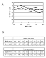
- FIG. 12 shows an example of the antenna gain characteristic of port 2.
- Port 1 is a level of a signal obtained by receiving a UHF band broadcast by the wire antenna element 102 and a received signal amplified by the LNA 125.
- Port 2 receives a UHF band broadcast by the rod antenna element 103, and receives the received signal. This is the level of the signal amplified by the LNA 126.
- the coaxial cable 105 and the coaxial cable 106 were 1.5 m in length.
- FIG. 11A and FIG. 12A are graphs, and FIG. 11B and FIG. 12B show data.
- the horizontal axis indicates the frequency (MHz)
- the vertical axis indicates the peak gain (dBd).
- the line labeled “H polarization” indicates the frequency-gain characteristic when receiving horizontal polarization
- the line labeled “V polarization” indicates the frequency-gain characteristic when receiving vertical polarization. .
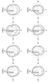
- FIG. 13 shows a measurement graph of directivity of the wire antenna element 102.
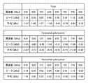
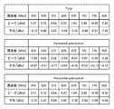
- FIG. 14 shows directivity measurement data of the wire antenna element 102.
- FIG. 14 shows measurement data at the time of horizontal polarization reception, measurement data at the time of vertical polarization reception, and total measurement data.
- FIG. 15 shows a measurement graph of directivity of the rod antenna element 103.
- FIG. 16 shows directivity measurement data of the rod antenna element 103.
- FIG. 16 shows measurement data at the time of horizontal polarization reception, measurement data at the time of vertical polarization reception, and total measurement data. Note that the solid line in the measurement graphs of FIGS. 13 and 15 indicates the directivity during horizontal polarization reception, and the dotted line indicates the directivity during vertical polarization reception.
- the directivity was measured in increments of 50 MHz in the range of 470 MHz to 770 MHz. Furthermore, the directivity at 906 MHz was measured.
- the antenna power under test (antenna device 10) is fixed on a rotating table when the radiation gain is measured, and the received power is measured while rotating the table and antenna element from an angle of 0 to 360 degrees in a horizontal plane.
- the gain distribution in the horizontal plane was measured.
- the illustrated measurement result is represented by a relative gain (unit: dBd) when the antenna gain is compared with a half-wave dipole antenna (maximum gain 2.15 dBi).
- FIG. 17 schematically shows orthogonal two cross polarizations (vertical polarization and horizontal polarization).
- FIG. 18 shows an example of the correlation coefficient between the wire antenna element 102 and the rod antenna element 103. It was confirmed that the correlation coefficient was lower than the set value. For example, it has been confirmed that the correlation coefficient is 0.3 or less.
- an antenna device having good reception sensitivity and resistance to noise is provided. Furthermore, an antenna device that is easy to install is provided. Furthermore, for example, since the antenna device can be downsized by removing the antenna element, the antenna device can be easily packed in a small box or the like.
- the drawing direction of the coaxial cable is the windshield side.
- a rod antenna element and a coaxial cable may be connected to the same side surface of the case. And you may make it pull out a coaxial cable to a driver
- the connection points of the antenna element, the ground element, and the coaxial cable to the case can be appropriately changed.
- the ground element in the above-described embodiment may be constituted by a rod antenna element, and the ground antenna element may be detachable from the case.
- the number of grooves formed in the jack of the case is not limited to two. For example, a total of four groove portions may be formed, two on each intersecting straight line. As shown in FIG. 20, it is possible to adjust the position of the ground element by switching the combination of the grooves into which the protrusions are inserted. Thereby, for example, the mounting angle of the ground element can be switched according to the angle of the pillar of the car.
- a plurality of ground elements may be connected to the case.
- the antenna element 102 in one embodiment described above may be constituted by a rod antenna element, and the antenna element 102 may be detachable from the case. That is, it is sufficient that at least one of the antenna element 102 and the antenna element 103 is detachable from the case. Furthermore, more antenna elements may be connected to the case.
- a cable that outputs a reception signal received by the antenna device is not limited to a coaxial cable, and a differential line may be used.
- This indication can also take the following composition.
- First and second antenna elements for receiving at least one of a broadcast wave and a signal transmitted by being superimposed on the broadcast wave; A ground element that functions as a common ground for the first and second antenna elements; An antenna device capable of adjusting an attachment angle of at least one of the first antenna element and the second antenna element.
- a first amplifier connected to the first antenna element and a second amplifier connected to the second antenna element are formed on the power feeding unit. (5) to (10) An antenna device according to claim 1.
- a cable for transmitting the signal is connected to the power supply unit, The antenna device according to any one of (5) to (11), wherein a ferrite material is used for the cable.
- a ferrite material is used for the cable.
- the metal foil tape is used for the cable.
- a cable for transmitting the signal is connected to the power supply unit, The antenna device according to any one of (5) to (11), wherein the cable includes a differential line.
Abstract
Priority Applications (4)
| Application Number | Priority Date | Filing Date | Title |
|---|---|---|---|
| EP14819649.6A EP3018758A4 (fr) | 2013-07-02 | 2014-05-01 | Dispositif d'antenne |
| US14/898,940 US20160372814A1 (en) | 2013-07-02 | 2014-05-01 | Antenna apparatus |
| BR112015032135A BR112015032135A8 (pt) | 2013-07-02 | 2014-05-01 | Dispositivo de antena |
| CN201480036372.8A CN105359340A (zh) | 2013-07-02 | 2014-05-01 | 天线装置 |
Applications Claiming Priority (2)
| Application Number | Priority Date | Filing Date | Title |
|---|---|---|---|
| JP2013139111A JP6067495B2 (ja) | 2013-07-02 | 2013-07-02 | アンテナ装置および車載用電子機器 |
| JP2013-139111 | 2013-07-02 |
Publications (1)
| Publication Number | Publication Date |
|---|---|
| WO2015001696A1 true WO2015001696A1 (fr) | 2015-01-08 |
Family
ID=52143303
Family Applications (1)
| Application Number | Title | Priority Date | Filing Date |
|---|---|---|---|
| PCT/JP2014/002384 WO2015001696A1 (fr) | 2013-07-02 | 2014-05-01 | Dispositif d'antenne |
Country Status (6)
| Country | Link |
|---|---|
| US (1) | US20160372814A1 (fr) |
| EP (1) | EP3018758A4 (fr) |
| JP (1) | JP6067495B2 (fr) |
| CN (1) | CN105359340A (fr) |
| BR (1) | BR112015032135A8 (fr) |
| WO (1) | WO2015001696A1 (fr) |
Cited By (3)
| Publication number | Priority date | Publication date | Assignee | Title |
|---|---|---|---|---|
| US10470546B2 (en) | 2013-08-23 | 2019-11-12 | Preemadonna Inc. | Systems, methods and apparatuses for decorating nails |
| US11103041B2 (en) | 2017-10-04 | 2021-08-31 | Preemadonna Inc. | Systems and methods of adaptive nail printing and collaborative beauty platform hosting |
| US11265444B2 (en) | 2013-08-23 | 2022-03-01 | Preemadonna Inc. | Apparatus for applying coating to nails |
Families Citing this family (4)
| Publication number | Priority date | Publication date | Assignee | Title |
|---|---|---|---|---|
| JP5444786B2 (ja) * | 2009-03-30 | 2014-03-19 | ソニー株式会社 | 受信装置 |
| JP5861455B2 (ja) * | 2011-12-28 | 2016-02-16 | ソニー株式会社 | アンテナ装置 |
| US10008788B2 (en) * | 2015-10-22 | 2018-06-26 | Toyota Motor Engineering & Manufacturing North America, Inc. | Intermediate ground for vehicles |
| CN113421389B (zh) * | 2021-06-23 | 2022-08-12 | 深圳市中天迅通信技术股份有限公司 | 一种用于pos机的天线装置 |
Citations (7)
| Publication number | Priority date | Publication date | Assignee | Title |
|---|---|---|---|---|
| JPH0449423U (fr) * | 1990-09-03 | 1992-04-27 | ||
| JPH088625A (ja) * | 1994-06-16 | 1996-01-12 | Yatsuku Kk | 車外取付型アンテナ |
| JPH1117595A (ja) | 1997-06-26 | 1999-01-22 | Nippon Denki Ido Tsushin Kk | 4面ダイバーシティアンテナ装置 |
| JP2000156608A (ja) * | 1998-04-30 | 2000-06-06 | Matsushita Electric Ind Co Ltd | アンテナ装置、デジタルテレビジョン放送受信装置 |
| JP2000216613A (ja) * | 1999-01-21 | 2000-08-04 | Asahi Glass Co Ltd | 自動車電話用サイド窓ガラスアンテナ |
| JP3580245B2 (ja) * | 2000-11-10 | 2004-10-20 | 日本電気株式会社 | 携帯端末 |
| JP4412137B2 (ja) * | 2004-09-29 | 2010-02-10 | 日立電線株式会社 | 同軸ケーブルの製造方法並びにその同軸ケーブルを用いた接続ケーブル |
Family Cites Families (9)
| Publication number | Priority date | Publication date | Assignee | Title |
|---|---|---|---|---|
| JPS5912059U (ja) * | 1982-07-15 | 1984-01-25 | 松下電工株式会社 | プロ−ブ |
| JPH11122021A (ja) * | 1997-10-13 | 1999-04-30 | Nippon Antenna Co Ltd | 車載用アンテナ装置 |
| US6362784B1 (en) * | 1998-03-31 | 2002-03-26 | Matsuda Electric Industrial Co., Ltd. | Antenna unit and digital television receiver |
| EP1517403A3 (fr) * | 2003-08-29 | 2006-04-12 | Fujitsu Ten Limited | Antenne à polarisation circulaire et combinaison d antennes avec une tel antenne |
| US7075429B2 (en) * | 2004-10-14 | 2006-07-11 | Cranbrook Marshall | Alarm with remote monitor and delay timer |
| JP3127558U (ja) * | 2006-09-25 | 2006-12-07 | マスプロ電工株式会社 | 屋内、屋外両用アンテナ |
| JP5444786B2 (ja) * | 2009-03-30 | 2014-03-19 | ソニー株式会社 | 受信装置 |
| WO2010134538A1 (fr) * | 2009-05-20 | 2010-11-25 | ソニー株式会社 | Dispositif d'antenne |
| JP2012084944A (ja) * | 2010-10-06 | 2012-04-26 | Keiyo Engineering:Kk | 車載用ダイバーシティアンテナ装置 |
-
2013
- 2013-07-02 JP JP2013139111A patent/JP6067495B2/ja active Active
-
2014
- 2014-05-01 WO PCT/JP2014/002384 patent/WO2015001696A1/fr active Application Filing
- 2014-05-01 US US14/898,940 patent/US20160372814A1/en not_active Abandoned
- 2014-05-01 BR BR112015032135A patent/BR112015032135A8/pt not_active Application Discontinuation
- 2014-05-01 EP EP14819649.6A patent/EP3018758A4/fr not_active Withdrawn
- 2014-05-01 CN CN201480036372.8A patent/CN105359340A/zh active Pending
Patent Citations (7)
| Publication number | Priority date | Publication date | Assignee | Title |
|---|---|---|---|---|
| JPH0449423U (fr) * | 1990-09-03 | 1992-04-27 | ||
| JPH088625A (ja) * | 1994-06-16 | 1996-01-12 | Yatsuku Kk | 車外取付型アンテナ |
| JPH1117595A (ja) | 1997-06-26 | 1999-01-22 | Nippon Denki Ido Tsushin Kk | 4面ダイバーシティアンテナ装置 |
| JP2000156608A (ja) * | 1998-04-30 | 2000-06-06 | Matsushita Electric Ind Co Ltd | アンテナ装置、デジタルテレビジョン放送受信装置 |
| JP2000216613A (ja) * | 1999-01-21 | 2000-08-04 | Asahi Glass Co Ltd | 自動車電話用サイド窓ガラスアンテナ |
| JP3580245B2 (ja) * | 2000-11-10 | 2004-10-20 | 日本電気株式会社 | 携帯端末 |
| JP4412137B2 (ja) * | 2004-09-29 | 2010-02-10 | 日立電線株式会社 | 同軸ケーブルの製造方法並びにその同軸ケーブルを用いた接続ケーブル |
Non-Patent Citations (1)
| Title |
|---|
| See also references of EP3018758A4 |
Cited By (9)
| Publication number | Priority date | Publication date | Assignee | Title |
|---|---|---|---|---|
| US10470546B2 (en) | 2013-08-23 | 2019-11-12 | Preemadonna Inc. | Systems, methods and apparatuses for decorating nails |
| US10477937B2 (en) | 2013-08-23 | 2019-11-19 | Preemadonna Inc. | Systems and apparatuses to apply a material to a nail |
| US10653225B2 (en) | 2013-08-23 | 2020-05-19 | Preemadonna Inc. | Apparatus for applying coating to nails |
| US10972631B2 (en) | 2013-08-23 | 2021-04-06 | Preemadonna, Inc. | Apparatus for applying coating to nails |
| US11082582B2 (en) | 2013-08-23 | 2021-08-03 | Preemadonna Inc. | Systems and methods to initiate and perform the painting of an area of interest on a finger |
| US11265444B2 (en) | 2013-08-23 | 2022-03-01 | Preemadonna Inc. | Apparatus for applying coating to nails |
| US11290615B2 (en) | 2013-08-23 | 2022-03-29 | Preemadonna Inc. | Systems and methods to initiate and perform the painting of an area of interest on a finger |
| US11103041B2 (en) | 2017-10-04 | 2021-08-31 | Preemadonna Inc. | Systems and methods of adaptive nail printing and collaborative beauty platform hosting |
| US11717070B2 (en) | 2017-10-04 | 2023-08-08 | Preemadonna Inc. | Systems and methods of adaptive nail printing and collaborative beauty platform hosting |
Also Published As
| Publication number | Publication date |
|---|---|
| CN105359340A (zh) | 2016-02-24 |
| US20160372814A1 (en) | 2016-12-22 |
| JP2015012585A (ja) | 2015-01-19 |
| BR112015032135A2 (pt) | 2017-07-25 |
| JP6067495B2 (ja) | 2017-01-25 |
| EP3018758A1 (fr) | 2016-05-11 |
| BR112015032135A8 (pt) | 2018-04-03 |
| EP3018758A4 (fr) | 2017-03-01 |
Similar Documents
| Publication | Publication Date | Title |
|---|---|---|
| WO2015001696A1 (fr) | Dispositif d'antenne | |
| JP5153300B2 (ja) | アンテナ | |
| WO2013099589A1 (fr) | Dispositif d'antenne | |
| JP2007158435A (ja) | ロッドアンテナ、ロッドアンテナの車両のリヤガラスへの取付方法、及びロッドアンテナを用いた受信装置 | |
| JP2010093781A (ja) | ガラスアンテナ | |
| JP5655522B2 (ja) | 車両用アンテナ装置 | |
| JP2013026697A (ja) | ガラスアンテナ及び窓ガラス | |
| WO2014104365A1 (fr) | Vitre avant de véhicule équipée d'une antenne en verre | |
| JP2010010962A (ja) | 車両用ガラスアンテナ及び車両用窓ガラス板 | |
| JP2010114782A (ja) | 車両用ガラスアンテナ及び車両用窓ガラス | |
| JP4948181B2 (ja) | アンテナ、アンテナ装置、及びアンテナ装置を備える処理装置 | |
| JP2020099003A (ja) | アンテナ装置、アンテナ装置付き窓ガラス及びアンテナシステム | |
| WO2012070303A1 (fr) | Antenne | |
| JP2010041256A (ja) | 車両用ガラスアンテナ及び車両用窓ガラス | |
| JP6007700B2 (ja) | ガラスアンテナ及び窓ガラス | |
| WO2011058878A1 (fr) | Antenne de vitre pour véhicule | |
| JP2007110390A (ja) | 自動車用高周波ガラスアンテナ | |
| JP6985598B2 (ja) | アンテナ及び窓ガラス | |
| JP2011193381A (ja) | 平面アンテナ | |
| JP3639845B2 (ja) | 衛星電波及び地上電波受信用アンテナ装置 | |
| JP2011087054A (ja) | 車両用ガラスアンテナ | |
| JP6492578B2 (ja) | 車両用ガラスアンテナ及び車両用窓ガラス | |
| WO2012105456A1 (fr) | Antenne intégrée dans du verre et vitre utilisée pour un véhicule la comportant | |
| JP5532942B2 (ja) | ガラスアンテナ | |
| KR200346079Y1 (ko) | 지상파 텔레비전 방송 수신을 위한 증폭기 내장형 차량및 실내용 스트립 안테나 |
Legal Events
| Date | Code | Title | Description |
|---|---|---|---|
| WWE | Wipo information: entry into national phase |
Ref document number: 201480036372.8 Country of ref document: CN |
|
| 121 | Ep: the epo has been informed by wipo that ep was designated in this application |
Ref document number: 14819649 Country of ref document: EP Kind code of ref document: A1 |
|
| WWE | Wipo information: entry into national phase |
Ref document number: 2014819649 Country of ref document: EP |
|
| WWE | Wipo information: entry into national phase |
Ref document number: 14898940 Country of ref document: US |
|
| NENP | Non-entry into the national phase |
Ref country code: DE |
|
| REG | Reference to national code |
Ref country code: BR Ref legal event code: B01A Ref document number: 112015032135 Country of ref document: BR |
|
| ENP | Entry into the national phase |
Ref document number: 112015032135 Country of ref document: BR Kind code of ref document: A2 Effective date: 20151221 |