WO2014208570A1 - Method and apparatus for measuring refractive index and method for manufacturing optical element - Google Patents
Method and apparatus for measuring refractive index and method for manufacturing optical element Download PDFInfo
- Publication number
- WO2014208570A1 WO2014208570A1 PCT/JP2014/066752 JP2014066752W WO2014208570A1 WO 2014208570 A1 WO2014208570 A1 WO 2014208570A1 JP 2014066752 W JP2014066752 W JP 2014066752W WO 2014208570 A1 WO2014208570 A1 WO 2014208570A1
- Authority
- WO
- WIPO (PCT)
- Prior art keywords
- refractive index
- light
- medium
- test object
- temperature
- Prior art date
- Legal status (The legal status is an assumption and is not a legal conclusion. Google has not performed a legal analysis and makes no representation as to the accuracy of the status listed.)
- Ceased
Links
Classifications
-
- G—PHYSICS
- G01—MEASURING; TESTING
- G01M—TESTING STATIC OR DYNAMIC BALANCE OF MACHINES OR STRUCTURES; TESTING OF STRUCTURES OR APPARATUS, NOT OTHERWISE PROVIDED FOR
- G01M11/00—Testing of optical apparatus; Testing structures by optical methods not otherwise provided for
- G01M11/02—Testing optical properties
- G01M11/0228—Testing optical properties by measuring refractive power
-
- G—PHYSICS
- G01—MEASURING; TESTING
- G01N—INVESTIGATING OR ANALYSING MATERIALS BY DETERMINING THEIR CHEMICAL OR PHYSICAL PROPERTIES
- G01N21/00—Investigating or analysing materials by the use of optical means, i.e. using sub-millimetre waves, infrared, visible or ultraviolet light
- G01N21/17—Systems in which incident light is modified in accordance with the properties of the material investigated
- G01N21/41—Refractivity; Phase-affecting properties, e.g. optical path length
- G01N21/45—Refractivity; Phase-affecting properties, e.g. optical path length using interferometric methods; using Schlieren methods
-
- G—PHYSICS
- G01—MEASURING; TESTING
- G01N—INVESTIGATING OR ANALYSING MATERIALS BY DETERMINING THEIR CHEMICAL OR PHYSICAL PROPERTIES
- G01N21/00—Investigating or analysing materials by the use of optical means, i.e. using sub-millimetre waves, infrared, visible or ultraviolet light
- G01N21/17—Systems in which incident light is modified in accordance with the properties of the material investigated
- G01N21/41—Refractivity; Phase-affecting properties, e.g. optical path length
- G01N21/4133—Refractometers, e.g. differential
- G01N2021/414—Correcting temperature effect in refractometers
Definitions
- the present invention relates to a method and apparatus for measuring a refractive index, and in
- the present invention is useful in measuring the refractive index of an optical element manufactured by molding .
- the refractive indices of molded lenses change depending on molding conditions.
- the refractive indices of molded lenses are generally measured by a minimum deviation method or a V-block method after the lenses are processed into prism shapes. This processing work takes much time, effort, and cost.
- the refractive indices of molded lenses change due to release of stress when it is processed.
- a technique for measuring the refractive indices of molded lenses nondestructively is required.
- NPL 1 proposes a method for calculating the refractive index by fitting an interference signal in a spectral domain with a function of wavelength.
- NPL 1 The method disclosed in NPL 1 requires that the thickness of a test object is known. Furthermore, since the interference signal is too complicated a function to be directly fit, the accuracy of measurement of the refractive index tends to decrease.
- a method for measuring the refractive index of a test object splits light from a light source into test light and reference light, introduces the test light into the test object, and measures interference light in which the test light that has passed through the test object and the reference light interfere with each other.
- the method includes a first measurement step of measuring a first phase difference that is a phase difference between the test light and the reference light when the test object is at a first temperature; a second measurement step of measuring a second phase difference that is a phase difference between the test light and the reference light when the test object is at a second temperature different from the first temperature; and a calculation step of calculating the refractive index of the test object by using the first phase difference, the second phase difference, and a known temperature coefficient of the refractive index of the test object.
- a method for manufacturing an optical element according to a second aspect of the present invention includes the steps of molding an optical element and
- an interference optical system configured to split light from the light source into test light and reference light, introduce the test light into a test object, and interfere the test light that has passed through the test object and the reference light with each other; a detection unit configured to detect the
- the calculation unit calculates the refractive index of the test object using a first phase difference that is a phase difference between the test light and the reference light
- a second phase difference that is a phase difference between the test light and the reference light when the test object is at a second temperature different from the first temperature, and a known temperature
- FIG. 1 is a block diagram of a refractive-index measuring apparatus according to a first embodiment of the present invention.
- FIG. 2 is a flowchart showing a procedure for calculating the refractive index of a test object with the refractive-index measuring apparatus according to the first embodiment of the present invention.
- FIGs. 3A and 3B are diagrams showing interference signals obtained by a detector of the refractive-index measuring apparatus according to the first embodiment of the present invention.
- FIG. 4 is a block diagram of a refractive-index measuring apparatus according to a second embodiment of the present invention.
- FIG. 5 is a block diagram of a refractive-index measuring apparatus according to a third embodiment of the present invention.
- FIG. 6 is a diagram showing a method for
- Fig. 1 is a block diagram of a refractive-index measuring apparatus according to a first embodiment of the present invention.
- the refractive-index measuring apparatus of this embodiment is a Mach-Zehnder interferometer.
- the test object is a lens having negative refracting power (the reciprocal of a focal length) .
- the refractive index and thickness of the test object are
- the ref active-index measuring apparatus is a device for measuring the refractive index of a test object
- the test object may be a lens, a flat plate, or any other refracting optical element.
- the refractive-index measuring apparatus includes a light source 10, an interference optical system, a tank 60 capable of containing a medium 70 and a test object 80, a detector 90, and a computer 100 and measures the refractive index of the test object 80.
- the tank 60 includes a
- temperature regulating mechanism for regulating the temperature of the test object 80 via the medium 70.
- the light source 10 is a light source having a wide wavelength band (for example, a supercontinuum light source) .
- the interference optical system splits light coming from the light source 10 into light passing through the test object 80 (test light) and light that does not pass through the test object 80 (reference light), superposes the test light and the reference light to interfere with each other, and guides the interference light to the detector 90.
- interference optical system includes beam splitters 20 and 21 and mirrors 30, 31, 40, 41, 50, and 51.
- An example of the beam splitters 20 and 21 is a cube beam splitter.
- the beam splitter 20 allows part of light coming from the light source 10 to pass through an interface (joining surface) 20a and reflects the remaining light from the interface.
- the light that has passed through the interface 20a is the reference light, and the light reflected from the interface 20a is the test light.
- the beam splitter 21 reflects part of the reference light from an interface 21a and allows part of the test light to pass through. This causes the test light and the reference light to interfere with each other to form interference light, and the interference light exits toward the detector 90.
- the tank 60 contains the medium 70 (for example, water or oil) and the test object 80.
- the optical path length of the test light and the optical path length of the reference light in the tank 60 may coincide with each other in a state in which the test object 80 is not arranged in the tank 60.
- the side of the tank 60 (for example, glass) may have a uniform thickness and refractive index, and two opposing sides may be parallel to each other.
- the tank 60 includes a temperature regulating mechanism (temperature control unit) and can increase or decrease the temperature of the medium 70 and control the temperature distribution of the medium 70. As the temperature of the medium 70 changes, the temperature of the test object 80 also changes. The temperature of the test object 80 is equal to that of the medium 70.
- the medium 70 may be air.
- the refractive index of the medium 70 is calculated by a medium-refractive-index calculation unit (not shown) .
- the medium-refractive-index calculation unit includes, for example, a temperature measuring unit that measures the temperature of the medium 70 and a computer that converts the measured temperature to a medium refractive index.
- the medium-refractive-index calculation unit may include a glass prism (reference test object) whose refractive index and shape are known, a wavefront measuring sensor (wavefront measuring unit) that measures the
- the transmitted wavefront of the glass prism arranged in the medium 70 and a computer that calculates the refractive index of the medium 70 from the transmitted wavefront and the refractive index and shape of the glass prism.
- An example of the mirrors 40 and 41 is a prism mirror.
- An example of the mirrors 50 and 51 is a corner cube reflector.
- the mirror 51 has a driving mechanism in the direction of an arrow in Fig. 1.
- the driving mechanism for the mirror 51 includes a stage having a large driving range, and a piezoelectric device having a high driving resolution.
- the driving amount of the mirror 51 is measured by a length measuring device (not shown) (for example, a laser length measuring device or an encoder) .
- the driving of the mirror 51 is controlled by the computer 100.
- the difference in optical path length between the test light and the reference light can be adjusted by the driving mechanism of the mirror 51.
- An example of the detector 90 is a spectrometer that disperses the interference light coming from the beam splitter 21 and detects the intensity of the interference light as a function of the wavelength (frequency) .
- the computer 100 functions both as a calculation unit for calculating the refractive index of the test object 80 from an interference signal output from the detector 90 and a control unit that controls the amount of driving of the mirror 51 and the temperature of the medium 70 and includes a CPU.
- the calculation unit that calculates the refractive index of the test object 80 from an interference signal output from the detector 90 and the control unit that controls the driving amount of the mirror 51 and the temperature of the medium 70 may be different computers .
- the interference optical system is adjusted so that the optical path lengths of the reference light and the test light are equal in a state in which the test object 80 is not arranged in the tank 60.
- a method for adjustment is as follows .
- the interference signal of the reference light and the test light is acquired in a state in which the test object 80 is not arranged on the test light path.
- measuring device for example, a laser length measuring device or an encoder.
- Interference signals in a spectral domain measured by the detector 90 in Fig. 1 when the test object 80 is arranged on the test light path are shown in Figs. 3A and 3B.
- Figs. 3A and 3B show interference signals measured when the test object 80 have different temperatures.
- Fig. 3A shows an interference signal when the test object 80 has a first temperature
- Fig. 3B shows an interference signal when the test object 80 has a second temperature.
- the phase difference ⁇ ( ⁇ ) between the test light and the reference light at a reference temperature T 0 is expressed by Math. 2.
- n s mple ( ) is the phase refractive index of the test object 80 at a reference temperature T 0
- n medium ⁇ is the phase refractive index of the medium 70 at the reference temperature T 0
- L is the geometric thickness of the test object 80 at the reference temperature T 0 .
- the refractive index includes a phase refractive index ⁇ ⁇ ( ⁇ ) for a phase velocity ⁇ ⁇ ( ⁇ ), which is the
- the refractive index is to be calculated.
- the temperature at which the refractive index is to be calculated is defined as the reference temperature T 0 , and a refractive index n sample ( ⁇ ) at the reference temperature T 0 is calculated.
- the sign ⁇ in Figs. 3A and 3B denotes a wavelength at which the phase difference ⁇ ( ⁇ ) takes an extreme value. Since the period of the interference signal is long at a wavelength in the vicinity of ⁇ , the interference signal can easily be measured. In contrast, at wavelengths remote from ⁇ , the period of the interference signal is short, thus causing the possibility of too dense interference pattern to resolve. If ⁇ 0 is out of the measurement range, ⁇ 0 may be adjusted by driving the mirror 51.
- Fig. 2 is a flowchart showing a procedure for calculating the phase refractive index of the test object 80, in which "S" is an abbreviation of step.
- the temperature of the test object 80 is adjusted to a first temperature ⁇ (S10) .
- the temperature of the test object 80 is adjusted by adjusting the temperature of the medium 70.
- a first phase difference ⁇ ( ⁇ ) is measured at the first temperature i (first measurement step S20) .
- An interference signal is obtained while the mirror 51 is being driven little by little.
- the first phase difference ⁇ ( ⁇ ) at the first temperature T x is calculated by Math. 4 using the phase shift amount 5 k and the interference intensity I k (X) .
- the phase shift amount 6 k is set to the smallest possible value, and the number of driving steps M is set to the largest possible value.
- the calculated phase difference ⁇ ( ⁇ ) is wrapped modulo 2 ⁇ . This requires the operation of connecting the phase jump of 2 ⁇ (unwrapping) .
- the phase difference obtained by the phase shift method includes any integer multiple of 2% (an unknown offset term) .
- ⁇ 1 ( ) tan 1 ⁇ 2 - [0037]
- the temperature of the test object 80 is adjusted to a second temperature T 2 (S30) .
- a second phase difference ⁇ 2 ( ⁇ ) is measured at the second temperature T 2
- the second phase difference ⁇ 2 ( ⁇ ) is measured by the phase shift method, as for the first phase difference ⁇ ⁇ ( ⁇ ) .
- the refractive index of the test object 80 is calculated using the first phase difference ⁇ ( ⁇ ), the second phase difference ⁇ 2 ( ⁇ ) , and a temperature coefficient ⁇ ( ⁇ )/ ⁇ of the refractive index (calculation step S50) .
- a method for calculation is as follows.
- phase refractive index ni sample ( ⁇ ) at the first temperature Ti first refractive index
- phase refractive index ⁇ 2 33 ⁇ 4 ⁇ 1 ⁇ ( ⁇ ) at the second temperature T 2 ( ⁇ ) second refractive index
- a Cauchy's dispersion formula is used as a function of the phase refractive index; alternatively, another refractive-index dispersion formula (for example, Sellmeier's formula) may be used.
- n ,ple (A) ⁇ ⁇ + ⁇ 2 ⁇ 2 + ⁇ 3 ⁇ ⁇ 2 + ⁇ 4 ⁇ ⁇ 4 + ⁇ 5 ⁇ * + ⁇ 6 ⁇ *
- fif* (A) /5 1 + 5 2 ⁇ 2 + ⁇ 3 ⁇ ⁇ 2 + ⁇ 4 ⁇ ⁇ 4 + ⁇ 5 ⁇ * + ⁇ 6 ⁇ *
- ⁇ med i um ⁇ of the medium 70 at the second temperature T 2 are known amounts measured by a medium-refractive-index
- a is the coefficient of linear expansion of the test object .80, which is a known amount.
- Unknown offset terms for the first phase difference and the second phase difference are expressed as 2 ⁇ and 2nm 2 , respectively.
- an assumed value of thickness is used in Math. 5.
- a designed thickness of the test object 80 may be used as the assumed value of thickness.
- the first term at the right side of Math. 7 is a difference in refractive index corresponding to the
- an assumed value of thickness may be selected for operation so that the difference between the phase refractive indices n i sampie ( ) a nd ⁇ sample ( ⁇ ) ig equal to the difference in
- the refractive index corresponding to the difference between the first temperature ⁇ and the second temperature T 2 is the thickness of the test object 80, and the calculated phase refractive indices ni sample U) and n 2 sample ( ) are the phase refractive indices of the test object 80.
- the phase refractive index ⁇ 33 ⁇ 1 ⁇ ( ⁇ ) of the test object 80 at the reference temperature T 0 is calculated by temperature conversion of the refractive index using Math. 8.
- the refractive index of the test object 80 is calculated (calculation step S50) .
- the first refractive index ni sample ( ) is. obtained by fitting the first phase difference ⁇ ( ⁇ ) with a refractive-index dispersion formula using the assumed value of thickness of the test object 80.
- the second refractive index n 2 sample ( ) is obtained by fitting the second phase difference ⁇ 2 ( ⁇ ) with a refractive-index dispersion formula using the assumed value of thickness of the test object 80.
- the difference between the first and second refractive indices obtained in the first and second steps, respectively, and the refractive index difference obtained by applying the difference between the first temperature Ti and the second temperature T 2 to the temperature coefficient of the refractive index of the test object 80 are compared.
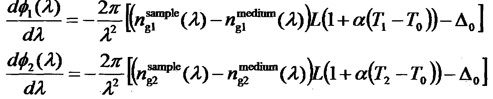
- the unknown amounts, 2 ⁇ and 2 ⁇ 2 can be removed by differentiating the first phase difference ⁇ ( ⁇ ) and the second phase difference ⁇ 2 ( ⁇ ) with respect to the wavelength.
- the differential of the first phase difference, ⁇ ( ⁇ )/ ⁇ and the differential of the second phase difference / d ⁇ 2 ( ⁇ ) / X are expressed by Math. 9.
- n g i samp e ( ) is the group refractive index of the test object 80 at the first temperature Ti
- n g2 sample ( ⁇ ) is the group refractive index of the test object 80 at the second temperature T 2
- n g i medlum ( ⁇ ) is the group refractive index of the medium 70 at the first temperature Ti
- n g 2 rae di um ( ⁇ ) is the group refractive index of the medium 70 at the second temperature T 2
- the group refractive indices n g i sarnple ( ⁇ ) and n g2 sample ( ) have the relationship expressed by Math.
- dn g ( )/dT is a temperature coefficient of the group refractive index and is expressed as Math. 11 using the temperature coefficient dn ( ⁇ ) /dT of the refractive index.
- a method for calculating the phase refractive index of the test object 80 from the group refractive index is as follows .
- phase refractive index ⁇ ⁇ ( ⁇ ) and the group refractive index N g ( ) have the relationship as in Math. 13, where C is an integration constant.
- integration constant c glass of the base material can be calculated using the value of the phase refractive index of the base material, provided by a glass manufacturer. Using the integration constant c glass and Math. 13 allows
- ⁇ 9 ( ⁇ ) is the group refractive index of the base material.
- test object 80 is arranged in the medium 70, such as oil, (a medium having a higher refractive index than that of air)
- the medium 70 may be air.
- arranging the test object 80 in the medium 70 has advantages.
- One of the advantages is that the decrease in the refractive index difference between the test object 80 and the medium 70 can decrease the influence of refraction by the lens. Another advantage is that the increase in the difference between the first phase difference and the second phase difference increases the calculation accuracy of the refractive index.
- the denominator at the right side of Math. 12 is an amount related to the difference between the first phase difference and the second phase difference.
- the difference between the first phase difference and the second phase difference increases as the difference between the first temperature ⁇ and the second temperature T 2 increases, thus increasing the accuracy of calculation of the refractive index.
- the difference between the first temperature Ti and the second temperature 2 may be as large as possible.
- the temperature distribution of the medium 70 causes the refractive index distribution of the medium 70
- the calculated refractive index of the test object 80 causes an error.
- the temperature distribution of the medium 70 may be controlled by a temperature regulating mechanism (temperature control unit) so as not to generate temperature distribution in the medium 70. Since an error due to the refractive index distribution of the medium 70 can be corrected if the amount of the refractive index distribution is found, a wavefront measuring device ( avefront measuring unit) for measuring the refractive index distribution of the medium 70 may be provided.
- coefficient of linear expansion a are known; for example, the value of the base material that glass manufacturer provides can be used. Strictly, although the temperature coefficient dn ( ⁇ ) /dT of the refractive index and the
- a set of the temperature coefficient of the refractive index of a glass material close in refractive index to the test object 80 may be known. Since the
- heterodyne interferometry may be used.
- the heterodyne interferometer emits pseudo-monochromatic light with a monochromator
- phase difference is calculated at each wavelength while the
- This embodiment uses a supercontinuum light source as the light source 10 having a wide wavelength band.
- a superluminescent diode (SLD) a superluminescent diode (SLD) , a halogen lamp, or a short pulse laser may be used.
- SLD superluminescent diode
- a halogen lamp a halogen lamp
- a short pulse laser may be used.
- a wavelength-swept light source may be used instead of a combination of the broadband light source and the monochromator .
- this embodiment has the configuration of a Mach-Zehnder interferometer, a Michelson interferometer may be used. Although this embodiment calculates the refractive index and the phase difference as functions of wavelength, they may be calculated as functions of frequency.
- this embodiment can calculate the refractive index of the test object 80 with high accuracy without measuring a correct thickness of the test object 80 by measuring the interference light under two kinds of
- the refractive-index measuring apparatus of this embodiment can measure the refractive index with high accuracy even if the thickness of the test object 80 is unknown.
- Fig. 4 is a block diagram of a refractive-index measuring apparatus according to a second embodiment of th present invention.
- This embodiment further includes an interferometer that measures the refractive index of the medium 70 in addition to the refractive-index measuring apparatus of the first embodiment.
- the test object 80 is lens having positive refracting power. The same
- Light emitted from the light source 10 is split into transmitted light and reflected light by a beam splitter 22.
- the transmitted light travels to an
- the interference optical system for measuring the refractive index of the test object 80 and the reflected light is guided to an interference optical system for measuring the refractive index of the medium 70.
- the reflected light is further split into transmitted light (medium reference light) and reflected light (medium test light) by a beam splitter 23.
- the medium test light reflected by the beam splitter 23 is reflected by mirrors 42 and 52, thereafter passes through the side of the tank 60 and the medium 70, and is then reflected by a mirror 33 to reach a beam splitter 24.
- the medium reference light that has passed through the beam splitter 23 is reflected by mirrors 32, 43, and 53 and thereafter passes through a compensating plate 61 to reach the beam splitter 24.
- the interference splitter 24 interfere with each other to form interference light.
- the interference light is detected by a detector 91, such as a spectrometer.
- the interference signal detected by the detector 91 is sent to the computer 100.
- the compensating plate 61 takes charge of
- the compensating plate 61 is made of the same material and has the same thickness as those of the side of the tank 60 (the thickness of the side of the tank 60 x 2) .
- the compensating plate 61 has the effect of making the optical path length difference between the medium test light and the medium reference light at individual wavelengths equal when air is included in the tank 60.
- the mirror 53 can be driven by the same driving mechanism as that for the. mirror 51 and can be driven in the direction of an arrow in Fig. 4.
- the driving of the mirror 53 is controlled by the computer 100.
- a procedure for calculating the phase refractive index of the test object 80 in this embodiment is as follows.
- the temperature of the test object 80 is adjusted to a first temperature (S10).
- a first phase difference is measured at the first temperature (first measurement step S20) .
- the phase difference r x ( ⁇ ) between the medium reference light and the medium test light at the first temperature is measured by the interferometer that measures the refractive index of the medium 70.
- i ( ⁇ ) between the medium reference light and the medium test light at the first temperature and the differential thereof d ⁇ l ( ⁇ )/d ⁇ are expressed by Math. 15.
- phase refractive index ni medlurn ( ) of the medium 70 can be calculated by performing fitting on the relational expression for ⁇ ( ⁇ ) in Math. 15 as in the method for calculating the phase refractive index ni sampIe ( ⁇ ) of the test object 80.
- the group refractive index n gl medium ( ⁇ ) of the medium 70 can be obtained by deforming d ⁇ ( ⁇ )/d ⁇ in Math. 15.
- the temperature of the test object 80 is adjusted to a second temperature (S30) .
- a second phase difference is measured at the second temperature (second measurement step S40) .
- the phase difference between the medium reference light and the medium test light at the second temperature is also measured by the interferometer that measures the refractive index of the medium 70.
- the refractive index of the medium 70 at the second temperature is calculated from the phase difference between the medium reference light and the medium test light at the second temperature.
- the refractive index of the test object 80 is calculated using the first phase difference, the second phase
- Fig. 5 is a block diagram of a refractive-index measuring apparatus according to a third embodiment.
- the transmitted wavefronts of the test object 80 and a glass prism (reference test object) 130 are measured by a two-dimensional sensor (wavefront measuring unit).
- the glass prism 130 whose refractive index and shape are known is arranged on the test light beam to measure the refractive index of the medium 70.
- the same configuration as those of the first and second embodiments will be described using the same reference signs.
- Light emitted from the light source 10 is split into pseudo-monochromatic light by a monochromator 95 and enters a pinhole 110.
- the wavelength of the pseudo- monochromatic light to be introduced into the pinhole 110 is controlled by the computer 100.
- the light that has passed through the pinhole 110 into diverging light is collimated by a collimator lens 120.
- the collimated light is split into transmitted light (reference light) and reflected light
- the reference light that has passed through the beam splitter 25 passes through the medium 70 in the tank 60 and is then reflected by the mirror 31 to reach a beam splitter 26.
- the mirror 31 has a driving mechanism in the direction of an arrow in Fig. 5 and is controlled by the computer 100.
- the test light reflected by the beam splitter 25 is reflected by the mirror 30 and enters the tank 60 that contains the medium 70, the test object 80, and the glass prism 130. Part of the test light passes through the medium 70 and the test object 80. Part of the test light passes through the medium 70 and the glass prism 130.
- a detector 92 for example, a CCD or CMOS
- the interference signal detected by the detector 92 is sent to the computer 100.
- the detector 92 is arranged at a conjugate position with respect to the test object 80 and the glass prism 130. If the phase refractive indices of the test object 80 and the medium 70 differ, the light that has passed through the test object 80 is diverged or converged. If the diverging light (converging light) intersects the light that has passed through other than the test object 80, the stray light may be cut by an aperture or the like arranged behind the test object 80 (on the detector 92 side) .
- the glass prism 130 may have a phase refractive index substantially equal to the phase refractive index of the medium 70 so as to prevent the interference pattern formed by the light that has passed through the glass prism 130 and the reference light from becoming excessively dense.
- the optical path lengths of the test light and the reference light are
- test object 80 and the glass prism 130 not arranged on the test light path.
- a procedure for calculating the phase refractive index of the test object 80 of this embodiment is as follows.
- the temperature of the test object 80 is adjusted to a first temperature (S10) .
- the first phase difference and the refractive index of the medium 70 are measured at the first temperature by wavelength sweeping using the monochromator 95 and a phase shift method using the driving mechanism for the mirror 31 (first measurement step S20) .
- the temperature of the test object 80 is adjusted to a second temperature (S30) .
- the second phase difference and the refractive index of the medium 70 are measured at the second temperature (second measurement step S40) .
- the refractive index of the test object 80 is calculated using the first phase difference, the second phase difference, and the temperature coefficient of the refractive index (calculation step S50) .
- results of measurement using the apparatuses and methods described in the first to third embodiments may be fed back to a method for manufacturing an optical element, such as a lens.
- Fig. 6 shows an example of an optical-element manufacturing process using molding.
- the optical element is manufactured through an optical-element designing step, a mold designing step, and an optical-element molding step using the mold.
- the form accuracy of the molded optical element is evaluated. If the accuracy is low, the mold is corrected, and molding is performed again. If the form accuracy is high, the optical performance of the optical element is evaluated.
Landscapes
- Analytical Chemistry (AREA)
- General Physics & Mathematics (AREA)
- Physics & Mathematics (AREA)
- Chemical & Material Sciences (AREA)
- General Health & Medical Sciences (AREA)
- Biochemistry (AREA)
- Life Sciences & Earth Sciences (AREA)
- Health & Medical Sciences (AREA)
- Immunology (AREA)
- Pathology (AREA)
- Investigating Or Analysing Materials By Optical Means (AREA)
- Testing Of Optical Devices Or Fibers (AREA)
- Instruments For Measurement Of Length By Optical Means (AREA)
Abstract
The present invention relates to measurement of the refractive index of a test object with high accuracy. Light from a light source 10 is split into test light and reference light. The refractive index of a test object 80 is measured by interferometry in which the test light that has passed through the test object 80 and the reference light are interfered with each other. A first phase difference is measured at a first temperature, a second phase difference is measured at a second temperature different from the first temperature, and the refractive index of the test object 80 is calculated using the first phase difference, the second phase difference, and the temperature coefficient of the refractive index of the test object 80.
Description
DESCRIPTION
METHOD AND APPARATUS FOR MEASURING REFRACTIVE INDEX AND METHOD FOR MANUFACTURING OPTICAL ELEMENT
Technical Field
[0001] The present invention relates to a method and apparatus for measuring a refractive index, and in
particular, the present invention is useful in measuring the refractive index of an optical element manufactured by molding .
Background Art
[0002] The refractive indices of molded lenses change depending on molding conditions. The refractive indices of molded lenses are generally measured by a minimum deviation method or a V-block method after the lenses are processed into prism shapes. This processing work takes much time, effort, and cost. Furthermore, the refractive indices of molded lenses change due to release of stress when it is processed. Thus, a technique for measuring the refractive indices of molded lenses nondestructively is required.
[0003] NPL 1 proposes a method for calculating the refractive index by fitting an interference signal in a spectral domain with a function of wavelength.
[0004] The method disclosed in NPL 1 requires that the
thickness of a test object is known. Furthermore, since the interference signal is too complicated a function to be directly fit, the accuracy of measurement of the refractive index tends to decrease.
Citation List
Non Patent Literature
[0005] NPL 1 H. Delbarre, C. Przygodzki, M. Tassou, D. Boucher, "High-precision index measurement in anisotropic crystals using white-light spectral interferometry" Applied Physics B, 2000, vol.70, pp.45-51.
Summary of Invention
[0006] A method for measuring the refractive index of a test object according to a first aspect of the present invention splits light from a light source into test light and reference light, introduces the test light into the test object, and measures interference light in which the test light that has passed through the test object and the reference light interfere with each other. The method includes a first measurement step of measuring a first phase difference that is a phase difference between the test light and the reference light when the test object is at a first temperature; a second measurement step of measuring a second phase difference that is a phase difference between the test light and the reference light when the test object is at a second temperature different from the first temperature; and
a calculation step of calculating the refractive index of the test object by using the first phase difference, the second phase difference, and a known temperature coefficient of the refractive index of the test object.
[0007] A method for manufacturing an optical element according to a second aspect of the present invention includes the steps of molding an optical element and
evaluating the molded optical element by measuring the refractive index of the optical element by using the above method for measuring a refractive index according to the first aspect of the present invention.
[0008] An apparatus for measuring a refractive index according to a third aspect of the present invention
includes a light source; an interference optical system configured to split light from the light source into test light and reference light, introduce the test light into a test object, and interfere the test light that has passed through the test object and the reference light with each other; a detection unit configured to detect the
interference light of the test light and the reference light; a calculation unit configured to calculate the refractive index of the test object by using an interference signal output from the detection unit; and a temperature control unit configured to control the temperature of the test object. The calculation unit calculates the refractive
index of the test object using a first phase difference that is a phase difference between the test light and the
reference light when the test object is at a first
temperature, a second phase difference that is a phase difference between the test light and the reference light when the test object is at a second temperature different from the first temperature, and a known temperature
coefficient of the refractive index of the test object.
[0009] Further features of the present invention will become apparent from the following description of exemplary embodiments with reference to the attached drawings.
Brief Description of Drawings
[0010] Fig. 1 is a block diagram of a refractive-index measuring apparatus according to a first embodiment of the present invention.
[0011] Fig. 2 is a flowchart showing a procedure for calculating the refractive index of a test object with the refractive-index measuring apparatus according to the first embodiment of the present invention.
[0012] Figs. 3A and 3B are diagrams showing interference signals obtained by a detector of the refractive-index measuring apparatus according to the first embodiment of the present invention.
[0013] Fig. 4 is a block diagram of a refractive-index measuring apparatus according to a second embodiment of the
present invention.
[0014] Fig. 5 is a block diagram of a refractive-index measuring apparatus according to a third embodiment of the present invention.
[0015] Fig. 6 is a diagram showing a method for
manufacturing an optical element according to a fourth embodiment of the present invention.
Description of Embodiments
[0016] Embodiments of the present invention will be
described hereinbelow with reference to the accompanying drawings .
First Embodiment
[0017] Fig. 1 is a block diagram of a refractive-index measuring apparatus according to a first embodiment of the present invention. The refractive-index measuring apparatus of this embodiment is a Mach-Zehnder interferometer. In this embodiment, the test object is a lens having negative refracting power (the reciprocal of a focal length) . The refractive index and thickness of the test object are
unknown. Since the ref active-index measuring apparatus is a device for measuring the refractive index of a test object, the test object may be a lens, a flat plate, or any other refracting optical element.
[0018] The refractive-index measuring apparatus includes a light source 10, an interference optical system, a tank 60
capable of containing a medium 70 and a test object 80, a detector 90, and a computer 100 and measures the refractive index of the test object 80. The tank 60 includes a
temperature regulating mechanism (temperature control unit) for regulating the temperature of the test object 80 via the medium 70.
[0019] The light source 10 is a light source having a wide wavelength band (for example, a supercontinuum light source) . The interference optical system splits light coming from the light source 10 into light passing through the test object 80 (test light) and light that does not pass through the test object 80 (reference light), superposes the test light and the reference light to interfere with each other, and guides the interference light to the detector 90. The
interference optical system includes beam splitters 20 and 21 and mirrors 30, 31, 40, 41, 50, and 51.
[0020] An example of the beam splitters 20 and 21 is a cube beam splitter. The beam splitter 20 allows part of light coming from the light source 10 to pass through an interface (joining surface) 20a and reflects the remaining light from the interface. The light that has passed through the interface 20a is the reference light, and the light reflected from the interface 20a is the test light. The beam splitter 21 reflects part of the reference light from an interface 21a and allows part of the test light to pass
through. This causes the test light and the reference light to interfere with each other to form interference light, and the interference light exits toward the detector 90.
[0021] The tank 60 contains the medium 70 (for example, water or oil) and the test object 80. The optical path length of the test light and the optical path length of the reference light in the tank 60 may coincide with each other in a state in which the test object 80 is not arranged in the tank 60. Accordingly, the side of the tank 60 (for example, glass) may have a uniform thickness and refractive index, and two opposing sides may be parallel to each other. The tank 60 includes a temperature regulating mechanism (temperature control unit) and can increase or decrease the temperature of the medium 70 and control the temperature distribution of the medium 70. As the temperature of the medium 70 changes, the temperature of the test object 80 also changes. The temperature of the test object 80 is equal to that of the medium 70. The medium 70 may be air.
[0022] The refractive index of the medium 70 is calculated by a medium-refractive-index calculation unit (not shown) . The medium-refractive-index calculation unit includes, for example, a temperature measuring unit that measures the temperature of the medium 70 and a computer that converts the measured temperature to a medium refractive index.
Alternatively, the medium-refractive-index calculation unit
may include a glass prism (reference test object) whose refractive index and shape are known, a wavefront measuring sensor (wavefront measuring unit) that measures the
transmitted wavefront of the glass prism arranged in the medium 70, and a computer that calculates the refractive index of the medium 70 from the transmitted wavefront and the refractive index and shape of the glass prism.
[0023] An example of the mirrors 40 and 41 is a prism mirror. An example of the mirrors 50 and 51 is a corner cube reflector. The mirror 51 has a driving mechanism in the direction of an arrow in Fig. 1. The driving mechanism for the mirror 51 includes a stage having a large driving range, and a piezoelectric device having a high driving resolution. The driving amount of the mirror 51 is measured by a length measuring device (not shown) (for example, a laser length measuring device or an encoder) . The driving of the mirror 51 is controlled by the computer 100. The difference in optical path length between the test light and the reference light can be adjusted by the driving mechanism of the mirror 51.
[0024] An example of the detector 90 is a spectrometer that disperses the interference light coming from the beam splitter 21 and detects the intensity of the interference light as a function of the wavelength (frequency) .
[0025] The computer 100 functions both as a calculation
unit for calculating the refractive index of the test object 80 from an interference signal output from the detector 90 and a control unit that controls the amount of driving of the mirror 51 and the temperature of the medium 70 and includes a CPU. Alternatively, the calculation unit that calculates the refractive index of the test object 80 from an interference signal output from the detector 90 and the control unit that controls the driving amount of the mirror 51 and the temperature of the medium 70 may be different computers .
[0026] The interference optical system is adjusted so that the optical path lengths of the reference light and the test light are equal in a state in which the test object 80 is not arranged in the tank 60. A method for adjustment is as follows .
[0027] In the refractive-index measuring apparatus in Fig. 1, the interference signal of the reference light and the test light is acquired in a state in which the test object 80 is not arranged on the test light path. The phase
difference φο(λ) between the reference light and the test light and the interference intensity Ιο(λ) are expressed by Math. 1.
[Math. 1]
70(2) = /0(l+rcosi¾)(2))
where λ is a wavelength in air, Δο is a difference in optical path length between the reference light and the test light, Io is the sum of the intensities of the reference light and the test light, and γ is visibility. In Math. 1, if Δο is not zero, the interference intensity I0 (λ) serves as an oscillating function. Accordingly, to make the optical path lengths of the test light and the reference light equal, the mirror 51 may be driven to a position where the interference signal does not serve as an oscillating function. At that time, Δ0 becomes zero.
[0028] Although the above embodiment has been described as applied to a case where the interference optical system is controlled so that the optical path lengths of the test light and the reference light become equal (Δ0 = 0) , the optical path lengths of the test light and the reference light may not necessarily be equal provided that the amount of shift of the mirror 51 from Δο = 0 can be found. The amount of driving of the mirror 51 from the position where the optical path lengths of the test light and the reference light (Δ0 = 0) are equal cart be measured by a length
measuring device (for example, a laser length measuring device or an encoder) .
[0029] Interference signals in a spectral domain measured by the detector 90 in Fig. 1 when the test object 80 is arranged on the test light path are shown in Figs. 3A and 3B.
Figs. 3A and 3B show interference signals measured when the test object 80 have different temperatures. Fig. 3A shows an interference signal when the test object 80 has a first temperature, and Fig. 3B shows an interference signal when the test object 80 has a second temperature. The phase difference φ(λ) between the test light and the reference light at a reference temperature T0 is expressed by Math. 2.

where, ns mple( ) is the phase refractive index of the test object 80 at a reference temperature T0, nmedium^) is the phase refractive index of the medium 70 at the reference temperature T0, and L is the geometric thickness of the test object 80 at the reference temperature T0.
[0030] The refractive index includes a phase refractive index Νρ(λ) for a phase velocity νρ(λ), which is the
traveling speed of light on an equiphase wave surface and a group refractive index Ν9(λ) for the traveling velocity of light energy (traveling velocity of wave packets) ν9(λ), which can be converted to each other using Math. 13,
described later.
[0031] Since the refractive index changes with temperature, it is necessary to specify a temperature at which the
refractive index is to be calculated. In this embodiment,
the temperature at which the refractive index is to be calculated is defined as the reference temperature T0, and a refractive index n sample (λ) at the reference temperature T0 is calculated.
[0032 ] The sign λο in Figs. 3A and 3B denotes a wavelength at which the phase difference φ(λ) takes an extreme value. Since the period of the interference signal is long at a wavelength in the vicinity of λο, the interference signal can easily be measured. In contrast, at wavelengths remote from λο, the period of the interference signal is short, thus causing the possibility of too dense interference pattern to resolve. If λ0 is out of the measurement range, Δ0 may be adjusted by driving the mirror 51.
[0033] Fig. 2 is a flowchart showing a procedure for calculating the phase refractive index of the test object 80, in which "S" is an abbreviation of step.
[0034] First, the temperature of the test object 80 is adjusted to a first temperature Τχ (S10) . The temperature of the test object 80 is adjusted by adjusting the temperature of the medium 70. Next, a first phase difference φι (λ) is measured at the first temperature i (first measurement step S20) .
[0035] The first phase difference φι(λ) at the first
temperature Τ χ can be measured by a phase shift method
described below. An interference signal is obtained while
the mirror 51 is being driven little by little. An interference intensity Ik( ) when the phase shift amount (= driving amount x 2%IX) of the mirror 51 is 6k (k = 0, 1, M-l) is expressed by Math. 3.
[Math. 3]
I kW= Io[ + r∞s(ifil(A) - Sk)]= a0 +alcosSk +a2smSk

[0036] The first phase difference φι (λ) at the first temperature Tx is calculated by Math. 4 using the phase shift amount 5k and the interference intensity Ik(X) . To increase the calculation accuracy of the phase difference φι(λ), the phase shift amount 6k is set to the smallest possible value, and the number of driving steps M is set to the largest possible value. The calculated phase difference φι (λ) is wrapped modulo 2π. This requires the operation of connecting the phase jump of 2π (unwrapping) . The phase difference obtained by the phase shift method includes any integer multiple of 2% (an unknown offset term) .
[Math. 4]


^1( )=tan1^2-
[0037] Next, the temperature of the test object 80 is adjusted to a second temperature T2 (S30) . A second phase difference φ2 (λ) is measured at the second temperature T2
(second measurement step S40) . The second phase difference φ2(λ) is measured by the phase shift method, as for the first phase difference φχ (λ) .
[0038] Lastly, the refractive index of the test object 80 is calculated using the first phase difference φι(λ), the second phase difference φ2 (λ) , and a temperature coefficient άη(λ)/άΤ of the refractive index (calculation step S50) . A method for calculation is as follows.
[0039] If the first phase difference φι(λ) and the second phase difference φ2 (λ) are fitted with Math. 5, integers mx and m2 and functions of a dispersion formula, Ak, Bk (k = 1, 2, 6) are given. In other words, the phase refractive index nisample (λ) at the first temperature Ti (first refractive index), and the phase refractive index η2 3¾ηρ1θ(λ) at the second temperature T2 (λ) (second refractive index) are calculated. Here, a Cauchy's dispersion formula is used as a function of the phase refractive index; alternatively, another refractive-index dispersion formula (for example, Sellmeier's formula) may be used.
[Math. 5]
* (A) = ~ " *"WW1 + - Γο))- Δο ]+ 2^
n,ple(A) = ^Αι + Α2λ2 +Α3λ~2 + Α4λ~4 + Α5Χ* +Α6Χ*

fif* (A) = /51 + 52Α2 +Β3λ~2 + Β4λ~4 +Β5λ* +Β6λ*
where the phase refractive index nimed:Lum (λ) of the medium 70 at the first temperature Ti and the phase refractive index
^medium ^ of the medium 70 at the second temperature T2 are known amounts measured by a medium-refractive-index
measuring unit, and a is the coefficient of linear expansion of the test object .80, which is a known amount. Unknown offset terms for the first phase difference and the second phase difference are expressed as 2πκΐι and 2nm2, respectively. Since the thickness L of the test object 80 is unknown, an assumed value of thickness is used in Math. 5. For example, a designed thickness of the test object 80 may be used as the assumed value of thickness. Although Math. 5 assumes that the optical path length difference Δ0 at the first temperature Τχ and the optical path length difference Δ0 at the second temperature T2 are equal, they may differ.
[0040] If the assumed value of thickness has an error AL (thickness error) from the true value L, the phase
refractive indices nisample( ) and η2 33ιηρ1θ(λ) obtained by
fitting with Math. 5 have refractive index errors Δηχ(λ) and Δη2(λ) due to the thickness error AL, respectively. The
refractive index errors Δηι ( λ ) and Δη2 ( λ ) are expressed by Math. 6.
[Math. 6]

[ 0041 ] If the assumed value of thickness has a thickness error Al>, the difference between the phase refractive indices nisample( ) and n2 sample( ) is expressed by Math. 7, where dn( )/dT is a known amount.
[Math. 7]

[ 0042 ] The first term at the right side of Math. 7 is a difference in refractive index corresponding to the
difference between the first temperature Ti and the second temperature T2. If the assumed value of thickness does not have the thickness error A , the difference between the phase refractive indices nisainple( ) and n2 sample( ) is equal to the first term of the right side of Math. 7. Thus, an assumed value of thickness may be selected for operation so that the difference between the phase refractive indices n isampie ( ) a nd ^sample (λ) ig equal to the difference in
refractive index corresponding to the difference between the
first temperature ΤΊ and the second temperature T2. The selected assumed value of thickness is the thickness of the test object 80, and the calculated phase refractive indices ni sampleU) and n2 sample( ) are the phase refractive indices of the test object 80. The phase refractive index η33πιρ1θ(λ) of the test object 80 at the reference temperature T0 is calculated by temperature conversion of the refractive index using Math. 8.
[0043] Thus, the refractive index of the test object 80 is calculated (calculation step S50) .
[Math. 8] al al
[0044] To select an assumed value of thickness for
calculation so that the difference between the phase
refractive indices nisample (λ) and n2 sample( ) and a difference in refractive index corresponding to the difference between the first temperature Ti and the second temperature T2 are equal, the following first to third steps may be repeated in the calculation step S50. In the first step, the first refractive index nisample( ) is. obtained by fitting the first phase difference φχ (λ) with a refractive-index dispersion formula using the assumed value of thickness of the test object 80. In the second step, the second refractive index n2 sample( ) is obtained by fitting the second phase difference
φ2 (λ) with a refractive-index dispersion formula using the assumed value of thickness of the test object 80. In the third step, the difference between the first and second refractive indices obtained in the first and second steps, respectively, and the refractive index difference obtained by applying the difference between the first temperature Ti and the second temperature T2 to the temperature coefficient of the refractive index of the test object 80 are compared. By repeating the first to third steps until the difference and the refractive index difference become equal while changing the assumed value of thickness of the test object 80, the influence of the thickness error AL of the test object 80 can be eliminated.
[0045] The unknown amounts, 2ππΐι and 2πΐΐΐ2, can be removed by differentiating the first phase difference φι (λ) and the second phase difference φ2(λ) with respect to the wavelength. The differential of the first phase difference, άφι(λ)/άλ and the differential of the second phase difference/ dφ2 (λ) / X are expressed by Math. 9.
[Math. 9]
[Math. 10]

[Math. 11]

[0046] Eliminating the thickness L of the test object 80 from Math. 9 gives the group refractive index of the test object 80 expressed by Math. 12.
[Math. 12]
λ2 <Ι2(λ) άη(λ)
fc -Γο)
(Γ2-Γ0) [ΐ+α(Γ2 - Γ0)]

[ 0047 ] A method for calculating the phase refractive index of the test object 80 from the group refractive index is as follows .
[ 0048] The phase refractive index Νρ(λ) and the group refractive index Ng( ) have the relationship as in Math. 13, where C is an integration constant.
[Math. 13]
dNv{X)

[ 0049] As can be found from Math. 13, there is only one way for calculating the group refractive index Ng (λ) from the phase refractive index Νρ(λ), whereas calculation of the phase refractive index Νρ(λ) from the group refractive index Ng( ) has an arbitrary property of the integration constant C. The phase refractive index Νρ(λ) cannot be calculated from information only on the group refractive index Ν9(λ).
[ 0050 ] Thus, calculation of the phase refractive index nsample( ) from the group refractive index η9 5Μιρΐ6(λ) of the
test object 80 needs assumption of the integration constant C. For example, assume that the integration constant csainple of the test object 80 is equal to the integration constant cgiass of a base material of the test object 80. The
integration constant cglass of the base material can be calculated using the value of the phase refractive index of the base material, provided by a glass manufacturer. Using the integration constant cglass and Math. 13 allows
calculation of the phase refractive index nsample ( ) from the group refractive index ng sample^) of the test object 80.
[ 0051 ] Instead of calculation of the integration constant C, a method of using the difference or the ratio between the phase refractive index and the group refractive index can be applied. The method for calculating a phase refractive index using the difference and the method using the ratio are expressed by Math. 14, where Νρ(λ) is the phase
refractive index of the base material, and Ν9(λ) is the group refractive index of the base material.
[Math. 14]
^sarcple ^ = ^ _ + ^sample

[ 0052 ] In this embodiment, although the test object 80 is arranged in the medium 70, such as oil, (a medium having a higher refractive index than that of air) , the medium 70 may
be air. However, arranging the test object 80 in the medium 70 has advantages.
[0053] One of the advantages is that the decrease in the refractive index difference between the test object 80 and the medium 70 can decrease the influence of refraction by the lens. Another advantage is that the increase in the difference between the first phase difference and the second phase difference increases the calculation accuracy of the refractive index. The denominator at the right side of Math. 12 is an amount related to the difference between the first phase difference and the second phase difference. The
increase in the denominator increases the accuracy of
calculation of the refractive index. In general, the
refractive index of a solid increases as the temperature increases, and the refractive index of liquid decreases as the temperature increases. Accordingly, arranging the test object 80 in a medium, such as oil, increases the difference between the first phase difference and the second phase difference .
[0054] The difference between the first phase difference and the second phase difference increases as the difference between the first temperature χ and the second temperature T2 increases, thus increasing the accuracy of calculation of the refractive index. Thus, the difference between the first temperature Ti and the second temperature 2 may be as
large as possible.
[0055] Since the temperature distribution of the medium 70 causes the refractive index distribution of the medium 70, the calculated refractive index of the test object 80 causes an error. Thus, the temperature distribution of the medium 70 may be controlled by a temperature regulating mechanism (temperature control unit) so as not to generate temperature distribution in the medium 70. Since an error due to the refractive index distribution of the medium 70 can be corrected if the amount of the refractive index distribution is found, a wavefront measuring device ( avefront measuring unit) for measuring the refractive index distribution of the medium 70 may be provided.
[0056] It is assumed that the temperature coefficient dn( )/dT (άης(λ)/άΤ) of the refractive index and the
coefficient of linear expansion a are known; for example, the value of the base material that glass manufacturer provides can be used. Strictly, although the temperature coefficient dn (λ) /dT of the refractive index and the
coefficient of linear expansion a of the test object 80 differ from the values of the base material, there is no problem even if they are equal to the values of the base material. This is because a slight change in the refractive index of the glass material hardly changes the temperature coefficient of the refractive index and the coefficient of
linear expansion, and the refractive indices nsamp (λ) and ng sample( ) calculated using Math. 7 and Math. 12 are
insensitive to changes in the temperature coefficient of the refractive index and the coefficient of linear expansion.
Accordingly, a set of the temperature coefficient of the refractive index of a glass material close in refractive index to the test object 80 may be known. Since the
influence of the coefficient of linear expansion on the refractive index is small, expansion of the test object 80 does not need to be taken into consideration (in other words, the coefficient of linear expansion may be zero) .
[0057] Although this embodiment measures the phase
difference using a combination of a mechanical phase shift using the mirror 51 and the spectral detection using the detector 90, heterodyne interferometry may be used. For the heterodyne interferometry, the heterodyne interferometer emits pseudo-monochromatic light with a monochromator
arranged directly after a light source, causes a frequency difference between the test light and the reference light with an acousto-optic device, and measures the interference signal with a detector, such as a photodiode. The phase difference is calculated at each wavelength while the
wavelength is swept with the monochromator.
[0058] This embodiment uses a supercontinuum light source as the light source 10 having a wide wavelength band.
Alternatively, a superluminescent diode (SLD) , a halogen lamp, or a short pulse laser may be used. In sweeping the wavelength, a wavelength-swept light source may be used instead of a combination of the broadband light source and the monochromator .
[0059] Although this embodiment has the configuration of a Mach-Zehnder interferometer, a Michelson interferometer may be used. Although this embodiment calculates the refractive index and the phase difference as functions of wavelength, they may be calculated as functions of frequency.
[0060] Since this embodiment performs fitting on. the phase difference, which is a simple function obtained from an interference signal, the fitting accuracy is high.
Furthermore, using Maths. 9 to 14 allows the refractive index to be calculated without performing fitting.
Furthermore, this embodiment can calculate the refractive index of the test object 80 with high accuracy without measuring a correct thickness of the test object 80 by measuring the interference light under two kinds of
temperature condition to remove the thickness error
component of the test object 80 or eliminate the thickness of the test object 80. In other words, the refractive-index measuring apparatus of this embodiment can measure the refractive index with high accuracy even if the thickness of the test object 80 is unknown.
Second Embodiment
[0061] Fig. 4 is a block diagram of a refractive-index measuring apparatus according to a second embodiment of th present invention. This embodiment further includes an interferometer that measures the refractive index of the medium 70 in addition to the refractive-index measuring apparatus of the first embodiment. The test object 80 is lens having positive refracting power. The same
configuration as that of the first embodiment will be described using the same reference signs.
[0062] Light emitted from the light source 10 is split into transmitted light and reflected light by a beam splitter 22. The transmitted light travels to an
interference optical system for measuring the refractive index of the test object 80, and the reflected light is guided to an interference optical system for measuring the refractive index of the medium 70. The reflected light is further split into transmitted light (medium reference light) and reflected light (medium test light) by a beam splitter 23.
[0063] The medium test light reflected by the beam splitter 23 is reflected by mirrors 42 and 52, thereafter passes through the side of the tank 60 and the medium 70, and is then reflected by a mirror 33 to reach a beam splitter 24. The medium reference light that has passed
through the beam splitter 23 is reflected by mirrors 32, 43, and 53 and thereafter passes through a compensating plate 61 to reach the beam splitter 24. The medium reference light and the medium test light that have reached the beam
splitter 24 interfere with each other to form interference light. The interference light is detected by a detector 91, such as a spectrometer. The interference signal detected by the detector 91 is sent to the computer 100.
[0064] The compensating plate 61 takes charge of
compensating the influence of refractive index dispersion due to the side of the tank 60. The compensating plate 61 is made of the same material and has the same thickness as those of the side of the tank 60 (the thickness of the side of the tank 60 x 2) . The compensating plate 61 has the effect of making the optical path length difference between the medium test light and the medium reference light at individual wavelengths equal when air is included in the tank 60.
[0065] The mirror 53 can be driven by the same driving mechanism as that for the. mirror 51 and can be driven in the direction of an arrow in Fig. 4. The driving of the mirror 53 is controlled by the computer 100.
[0066] A procedure for calculating the phase refractive index of the test object 80 in this embodiment is as follows.
[0067] First, the temperature of the test object 80 is
adjusted to a first temperature (S10). A first phase difference is measured at the first temperature (first measurement step S20) . When the first phase difference is measured, the phase difference r x (λ) between the medium reference light and the medium test light at the first temperature is measured by the interferometer that measures the refractive index of the medium 70. The phase difference r|i (λ) between the medium reference light and the medium test light at the first temperature and the differential thereof dηl(λ)/dλ are expressed by Math. 15.
[Math. 15]

where Ltank is the distance between two opposing sides of the tank 60 (optical path length of the medium test light in the medium 70) , Δ is the optical path difference between the medium reference light and the medium test light, which is a known amount. The phase refractive index nimedlurn( ) of the medium 70 can be calculated by performing fitting on the relational expression for ηι (λ) in Math. 15 as in the method for calculating the phase refractive index nisampIe (λ) of the test object 80. The group refractive index ngl medium (λ) of the medium 70 can be obtained by deforming dη^(λ)/dλ in Math. 15.
[0068] Next, the temperature of the test object 80 is adjusted to a second temperature (S30) . A second phase difference is measured at the second temperature (second measurement step S40) . When the second phase difference is measured, the phase difference between the medium reference light and the medium test light at the second temperature is also measured by the interferometer that measures the refractive index of the medium 70. The refractive index of the medium 70 at the second temperature is calculated from the phase difference between the medium reference light and the medium test light at the second temperature. Lastly, the refractive index of the test object 80 is calculated using the first phase difference, the second phase
difference, and the temperature coefficient of the
refractive index (calculation step S50) .
Third Embodiment
[0069] Fig. 5 is a block diagram of a refractive-index measuring apparatus according to a third embodiment. In this embodiment, the transmitted wavefronts of the test object 80 and a glass prism (reference test object) 130 are measured by a two-dimensional sensor (wavefront measuring unit). The glass prism 130 whose refractive index and shape are known is arranged on the test light beam to measure the refractive index of the medium 70. The same configuration as those of the first and second embodiments will be
described using the same reference signs.
[0070] Light emitted from the light source 10 is split into pseudo-monochromatic light by a monochromator 95 and enters a pinhole 110. The wavelength of the pseudo- monochromatic light to be introduced into the pinhole 110 is controlled by the computer 100. The light that has passed through the pinhole 110 into diverging light is collimated by a collimator lens 120. The collimated light is split into transmitted light (reference light) and reflected light
(test light) by a beam splitter 25.
[0071] The reference light that has passed through the beam splitter 25 passes through the medium 70 in the tank 60 and is then reflected by the mirror 31 to reach a beam splitter 26. The mirror 31 has a driving mechanism in the direction of an arrow in Fig. 5 and is controlled by the computer 100.
[0072] The test light reflected by the beam splitter 25 is reflected by the mirror 30 and enters the tank 60 that contains the medium 70, the test object 80, and the glass prism 130. Part of the test light passes through the medium 70 and the test object 80. Part of the test light passes through the medium 70 and the glass prism 130. The
remaining of the test light passes through only the medium 70. Each light that has passed through the tank 60
interferes with the reference light in the beam splitter 26
to form interference light. The interference light is detected by a detector 92 (for example, a CCD or CMOS
sensor) via an image-forming lens 121. The interference signal detected by the detector 92 is sent to the computer 100.
[0073] The detector 92 is arranged at a conjugate position with respect to the test object 80 and the glass prism 130. If the phase refractive indices of the test object 80 and the medium 70 differ, the light that has passed through the test object 80 is diverged or converged. If the diverging light (converging light) intersects the light that has passed through other than the test object 80, the stray light may be cut by an aperture or the like arranged behind the test object 80 (on the detector 92 side) . The glass prism 130 may have a phase refractive index substantially equal to the phase refractive index of the medium 70 so as to prevent the interference pattern formed by the light that has passed through the glass prism 130 and the reference light from becoming excessively dense. The optical path lengths of the test light and the reference light are
adjusted to be equal, with the test object 80 and the glass prism 130 not arranged on the test light path.
[0074] A procedure for calculating the phase refractive index of the test object 80 of this embodiment is as follows.
[0075] First, the temperature of the test object 80 is
adjusted to a first temperature (S10) . The first phase difference and the refractive index of the medium 70 are measured at the first temperature by wavelength sweeping using the monochromator 95 and a phase shift method using the driving mechanism for the mirror 31 (first measurement step S20) . Next, the temperature of the test object 80 is adjusted to a second temperature (S30) . The second phase difference and the refractive index of the medium 70 are measured at the second temperature (second measurement step S40) . Lastly, the refractive index of the test object 80 is calculated using the first phase difference, the second phase difference, and the temperature coefficient of the refractive index (calculation step S50) .
Fourth Embodiment
[0076] The results of measurement using the apparatuses and methods described in the first to third embodiments may be fed back to a method for manufacturing an optical element, such as a lens.
[0077] Fig. 6 shows an example of an optical-element manufacturing process using molding.
[0078] The optical element is manufactured through an optical-element designing step, a mold designing step, and an optical-element molding step using the mold. The form accuracy of the molded optical element is evaluated. If the accuracy is low, the mold is corrected, and molding is
performed again. If the form accuracy is high, the optical performance of the optical element is evaluated.
Incorporating the refractive-index measuring method of the present invention into the optical-performance evaluation step allows high-accuracy mass production of molded optical elements .
[0079] If the optical performance is low, an optical element whose optical surface is corrected is redesigned.
[0080] The above embodiments are merely representative examples, and various modifications and changes can be made on the embodiments in implementing the present invention.
[0081] While the present invention has been described with reference to exemplary embodiments, it is to be understood that the invention is not limited to the disclosed exemplary embodiments. The scope of the following claims is to be accorded the broadest interpretation so as to encompass all such modifications and equivalent structures and functions.
[0082] This application claims the benefit of Japanese Patent Application No. 2013-136169, filed June 28, 2013, which is hereby incorporated by reference herein in its entirety .
Claims
[1] A method for measuring the refractive index of a test object by splitting light from a light source into test light and reference light, by introducing the test light into the test object, and by measuring interference light in which the test light that has passed through the test object and the reference light interfere with each other, the method comprising:
a first measurement step of measuring a first phase difference that is a phase difference between the test light and the reference light when the test object is at a first temperature ;
a second measurement step of measuring a second phase difference that is a phase difference between the test light and the reference light when the test object is at a second temperature different from the first temperature; and
a calculation step of calculating the refractive index of the test object by using the first phase difference, the second phase difference, and a known temperature coefficient of the refractive index of the test object.
[2] The method for calculating a refractive index according to Claim 1, wherein the calculation step includes:
a first step of obtaining a first refractive index by fitting the first phase difference with a refractive-index
dispersion formula using an assumed value of thickness of the test object;
a second step of obtaining a second refractive index by fitting the second phase difference with a refractive-index dispersion formula using the assumed value of thickness; and a third step of comparing a difference between the first and second refractive indices obtained in the first and second steps and a refractive index difference obtained by applying the difference between the first temperature and the second temperature to the temperature coefficient of the refractive index of the test object,
wherein the first to third steps are repeated until the difference and the refractive index difference become equal, with the assumed value of thickness varied.
[3] The method for calculating a refractive index according to Claim 1, wherein in the calculation step,
the refractive index of the test object is calculated by calculating the differential of the first phase
difference and the differential of the second phase
difference and performing an operation for eliminating the thickness of the test object by using the differential of the first phase difference and the differential of the second phase difference.
[4] The method for calculating a refractive index according to one of Claims 1 to 3, wherein the interference light is
measured in a state in which the test object is arranged in a medium having a refractive index higher than the
refractive index of air.
[5] The method for calculating a refractive index according to Claim 4, wherein the refractive index of the medium is calculated by measuring the temperature of the medium and converting the measured temperature of the medium to the refractive index of the medium.
[6] The method for calculating a refractive index according to Claim 4, wherein a reference test object whose refractive index and shape are known is arranged in the medium, the transmitted wavefront of the reference test object is
measured by introducing light into the reference test object, and the refractive index of the medium is calculated by using the refractive index and the shape of the reference test object and the transmitted wavefront of the reference test object.
[7] The method for calculating a refractive index according to Claim 4, wherein the light from the light source is split into medium test light and medium reference light, the medium test light is introduced into the medium,
interference light in which the medium test light that has passed through the medium and the medium reference light are interfered with each other is measured, .and the refractive index of the medium is calculated by using a phase
difference between the medium reference light and the medium test light.
[8] The method for calculating a refractive index according to one of Claims 4 to 7, further comprising the step of measuring the refractive index distribution of the medium.
[9] The method for calculating a refractive index according to one of Claims 4 to 8, further comprising the step of controlling the temperature distribution of the medium.
[10] A method for manufacturing an optical element,
comprising the steps of:
molding an optical element; and
evaluating the molded optical element by measuring the refractive index of the optical element by using the method for measuring a refractive index according to one of Claims 1 to 9.
[11] An apparatus for measuring a refractive index, the apparatus comprising:
a light source;
an interference optical system configured to split light from the light source into test light and reference light, introduce the test light into a test object, and interfere the test light that has passed through the test object and the reference light with each other;
a detection unit configured to detect the interference light of the test light and the reference light;
a calculation unit configured to calculate the refractive index of the test object by using an interference signal output from the detection unit; and
a temperature control unit configured to control the temperature of the test object,
wherein the calculation unit calculates the refractive index of the test object using a first phase difference that is a phase difference between the test light and the
reference light when the test object is at a first
temperature, a second phase difference that is a phase difference between the test light and the reference light when the test object is at a second temperature different from the first temperature, and a known temperature
coefficient of the refractive index of the test object.
[12] The apparatus for measuring a refractive index
according to Claim 11, wherein
the calculation unit performs:
a first step of obtaining a first refractive index by fitting the first phase difference with a refractive- index dispersion formula using an assumed value of thickness of the test object;
a second step of obtaining a second refractive index by fitting the second phase difference with a
refractive-index dispersion formula using the assumed value of thickness; and
a third step of comparing a difference between the first and second refractive indices obtained in the first and second steps and a refractive index difference obtained by applying the difference between the first temperature and the second temperature to the temperature coefficient of the refractive index of the test object,
and repeats the first to third steps until the
difference and the refractive index difference become equal, with the assumed value of thickness varied.
[13] The apparatus for measuring a refractive index
according to Claim 11, wherein the calculation unit
calculates the refractive index of the test object by calculating the differential of the. first phase difference and the differential of the second phase difference and by performing an operation for eliminating the thickness of the test object by using the differential of the first phase difference and the differential of the second phase
difference .
[14] The apparatus for measuring a refractive index
according to one of Claims 11 to 13, wherein the
interference light is measured in a state in which the test object is arranged in a medium having a refractive index higher than the refractive index of air.
[15] The apparatus for measuring a refractive index
according to Claim 14, further comprising a temperature
measuring unit configured to measure the temperature of the medium,
wherein the calculation unit calculates the refractive index of the medium by converting , the temperature of the medium measured by the temperature measuring unit to the refractive index of the medium.
[16] The apparatus for measuring a refractive index
according to Claim 14, further comprising:
a reference test object whose refractive index and shape are known; and
a wavefront measuring unit configured to measure the transmitted wavefront of light introduced into the reference test object arranged in the medium,
wherein the calculation unit calculates the refractive index of the medium by using the refractive index and the shape of the reference test object and the transmitted wavefront of the reference test object.
[17] The apparatus for measuring a refractive index
according to Claim 14, further comprising:
an interference optical system configured to split the light from the light source into medium test light and medium reference light, introduce the medium test light into the medium, and interfere the medium test light that has passed through the medium with the medium reference light; a detection unit configured to detect the interference
light of the medium test light and the medium reference light; and
a calculation unit configured to calculate the
refractive index of the medium by using the phase difference between the medium reference light and the medium test light.
[18] The apparatus for measuring a refractive index
according to one of Claims 11 to 17, further comprising a wavefront measuring unit configured to measure the
refractive index distribution of the medium.
[19] The apparatus for measuring a refractive index
according to one of Claims 11 to 18, further comprising a temperature control unit configured to control the
temperature distribution of the medium.
Priority Applications (1)
| Application Number | Priority Date | Filing Date | Title |
|---|---|---|---|
| CN201480036877.4A CN105339779A (en) | 2013-06-28 | 2014-06-18 | Method and apparatus for measuring refractive index and method for manufacturing optical element |
Applications Claiming Priority (2)
| Application Number | Priority Date | Filing Date | Title |
|---|---|---|---|
| JP2013-136169 | 2013-06-28 | ||
| JP2013136169A JP6157241B2 (en) | 2013-06-28 | 2013-06-28 | Refractive index measuring method, refractive index measuring apparatus, and optical element manufacturing method |
Publications (1)
| Publication Number | Publication Date |
|---|---|
| WO2014208570A1 true WO2014208570A1 (en) | 2014-12-31 |
Family
ID=52141902
Family Applications (1)
| Application Number | Title | Priority Date | Filing Date |
|---|---|---|---|
| PCT/JP2014/066752 Ceased WO2014208570A1 (en) | 2013-06-28 | 2014-06-18 | Method and apparatus for measuring refractive index and method for manufacturing optical element |
Country Status (4)
| Country | Link |
|---|---|
| JP (1) | JP6157241B2 (en) |
| CN (1) | CN105339779A (en) |
| TW (1) | TWI524062B (en) |
| WO (1) | WO2014208570A1 (en) |
Cited By (1)
| Publication number | Priority date | Publication date | Assignee | Title |
|---|---|---|---|---|
| WO2016198182A1 (en) * | 2015-06-10 | 2016-12-15 | Robert Bosch Gmbh | Interferometric device and system for measuring the refractive index of a medium |
Families Citing this family (3)
| Publication number | Priority date | Publication date | Assignee | Title |
|---|---|---|---|---|
| JP2015010920A (en) * | 2013-06-28 | 2015-01-19 | キヤノン株式会社 | Refractive index measuring method, refractive index measuring apparatus, and optical element manufacturing method |
| CN106918576A (en) * | 2017-04-26 | 2017-07-04 | 广东工业大学 | A kind of non-contact type thin film temperature refraction rate measurement apparatus and method |
| CN108732132B (en) * | 2018-07-28 | 2020-05-19 | 华中科技大学 | Data processing method in refractive index measurement process based on photoelectric sensing array |
Citations (3)
| Publication number | Priority date | Publication date | Assignee | Title |
|---|---|---|---|---|
| JPH03218432A (en) * | 1989-10-12 | 1991-09-26 | Asahi Optical Co Ltd | Method and device for measuring refraction factor distribution |
| JP2011107052A (en) * | 2009-11-20 | 2011-06-02 | Canon Inc | Refractive index distribution measurement system and method of measuring refractive index distribution |
| US20120069350A1 (en) * | 2010-09-16 | 2012-03-22 | Canon Kabushiki Kaisha | Measuring method of refractive index and measuring apparatus of refractive index |
Family Cites Families (6)
| Publication number | Priority date | Publication date | Assignee | Title |
|---|---|---|---|---|
| US5151752A (en) * | 1988-06-16 | 1992-09-29 | Asahi Kogaku Kogyo K.K. | Method of measuring refractive indices of lens and sample liquid |
| JP3264469B2 (en) * | 1993-12-07 | 2002-03-11 | 富士写真フイルム株式会社 | Measurement device of refractive index distribution information of light scattering medium |
| JP3496878B2 (en) * | 2000-09-05 | 2004-02-16 | 日本電信電話株式会社 | Chromatic dispersion and loss wavelength dependence measuring device |
| JP5008650B2 (en) * | 2008-12-25 | 2012-08-22 | キヤノン株式会社 | Refractive index distribution measuring method and refractive index distribution measuring apparatus |
| JP5563439B2 (en) * | 2010-12-22 | 2014-07-30 | 日本電信電話株式会社 | Optical phase measuring device, optical phase measuring method and program |
| JP2013024720A (en) * | 2011-07-21 | 2013-02-04 | Canon Inc | Refractive index measurement method, refractive index measurement instrument, and refractive index measurement program |
-
2013
- 2013-06-28 JP JP2013136169A patent/JP6157241B2/en not_active Expired - Fee Related
-
2014
- 2014-06-18 WO PCT/JP2014/066752 patent/WO2014208570A1/en not_active Ceased
- 2014-06-18 CN CN201480036877.4A patent/CN105339779A/en active Pending
- 2014-06-26 TW TW103122075A patent/TWI524062B/en not_active IP Right Cessation
Patent Citations (3)
| Publication number | Priority date | Publication date | Assignee | Title |
|---|---|---|---|---|
| JPH03218432A (en) * | 1989-10-12 | 1991-09-26 | Asahi Optical Co Ltd | Method and device for measuring refraction factor distribution |
| JP2011107052A (en) * | 2009-11-20 | 2011-06-02 | Canon Inc | Refractive index distribution measurement system and method of measuring refractive index distribution |
| US20120069350A1 (en) * | 2010-09-16 | 2012-03-22 | Canon Kabushiki Kaisha | Measuring method of refractive index and measuring apparatus of refractive index |
Non-Patent Citations (2)
| Title |
|---|
| DJURISIC AB ET AL.: "Modeling the temperature dependence of the index of refraction of liquid water in the visible and the near-ultraviolet ranges by a genetic algorithm", APPLIED OPTICS, vol. 38, no. 1, 1 January 1999 (1999-01-01), pages 11 - 17 * |
| EL-KASHEF H: "The necessary requirements imposed on polar dielectric laser dye solvents", PHYSICA B, vol. 279, 2000, pages 295 - 301, XP007921517, DOI: doi:10.1016/S0921-4526(99)00856-X * |
Cited By (1)
| Publication number | Priority date | Publication date | Assignee | Title |
|---|---|---|---|---|
| WO2016198182A1 (en) * | 2015-06-10 | 2016-12-15 | Robert Bosch Gmbh | Interferometric device and system for measuring the refractive index of a medium |
Also Published As
| Publication number | Publication date |
|---|---|
| JP6157241B2 (en) | 2017-07-05 |
| JP2015010922A (en) | 2015-01-19 |
| TWI524062B (en) | 2016-03-01 |
| TW201502492A (en) | 2015-01-16 |
| CN105339779A (en) | 2016-02-17 |
Similar Documents
| Publication | Publication Date | Title |
|---|---|---|
| TWI521195B (en) | Mothod for measuring refractive index, refractive index measuring device, and method for producing optical element | |
| KR101390721B1 (en) | Measuring method of refractive index and measuring apparatus of refractive index | |
| JP4895409B2 (en) | Refractive index distribution measuring method and refractive index distribution measuring apparatus | |
| KR101812541B1 (en) | Temperature measuring method and storage medium | |
| US20160363531A1 (en) | Refractive index measurement method, measurement apparatus, and optical element manufacturing method | |
| KR102079588B1 (en) | Method measuring thickness and refractive index of planar samples based on fabry-perot interferometer | |
| KR102859530B1 (en) | Optical measurement apparatus, wavelength calibration method and standard sample | |
| WO2014208570A1 (en) | Method and apparatus for measuring refractive index and method for manufacturing optical element | |
| EP2718666A1 (en) | Coupled multi-wavelength confocal systems for distance measurements | |
| US20170315053A1 (en) | Refractive index measurement method, refractive index measurement apparatus, and optical element manufacturing method | |
| JP2015105850A (en) | Refractive index measuring method, refractive index measuring apparatus, and optical element manufacturing method | |
| JP2015099133A (en) | Measurement method and measurement device for thickness | |
| JP6207383B2 (en) | Refractive index distribution measuring method, refractive index distribution measuring apparatus, and optical element manufacturing method | |
| JP2016223982A (en) | Measurement method, measurement device, and optical element manufacturing method | |
| KR101108693B1 (en) | Apparatus and method for measuring refractive index based on white light interferometer | |
| JP2018004409A (en) | Refractive index measurement method, refractive index measurement device, and method of manufacturing optical element | |
| JP2015010920A (en) | Refractive index measuring method, refractive index measuring apparatus, and optical element manufacturing method | |
| JP5868227B2 (en) | Refractive index measuring method and refractive index measuring apparatus | |
| CN213843029U (en) | Refractive index measurement device based on optical coherence image | |
| JP2015210241A (en) | Wavefront measuring method, wavefront measuring apparatus, and optical element manufacturing method | |
| JP2012242163A (en) | Method for manufacturing optical tomographic image acquisition apparatus | |
| KR20250176118A (en) | Optic phase detection based transparent layer sensing system and measurement method thereof | |
| JP2016109595A (en) | Refractive index distribution measurement method, refractive index distribution measurement device, and optical element manufacturing method | |
| Shioda et al. | Spatially-resolved spectroscopy for simultaneous distinguishment of both structures and materials | |
| JP2016109592A (en) | Refractive index distribution measurement method, refractive index distribution measurement device, and optical element manufacturing method |
Legal Events
| Date | Code | Title | Description |
|---|---|---|---|
| WWE | Wipo information: entry into national phase |
Ref document number: 201480036877.4 Country of ref document: CN |
|
| 121 | Ep: the epo has been informed by wipo that ep was designated in this application |
Ref document number: 14817915 Country of ref document: EP Kind code of ref document: A1 |
|
| NENP | Non-entry into the national phase |
Ref country code: DE |
|
| 122 | Ep: pct application non-entry in european phase |
Ref document number: 14817915 Country of ref document: EP Kind code of ref document: A1 |