WO2014208336A1 - 質量分析方法 - Google Patents
質量分析方法 Download PDFInfo
- Publication number
- WO2014208336A1 WO2014208336A1 PCT/JP2014/065427 JP2014065427W WO2014208336A1 WO 2014208336 A1 WO2014208336 A1 WO 2014208336A1 JP 2014065427 W JP2014065427 W JP 2014065427W WO 2014208336 A1 WO2014208336 A1 WO 2014208336A1
- Authority
- WO
- WIPO (PCT)
- Prior art keywords
- ions
- voltage
- mass
- precursor ions
- auxiliary
- Prior art date
- Legal status (The legal status is an assumption and is not a legal conclusion. Google has not performed a legal analysis and makes no representation as to the accuracy of the status listed.)
- Ceased
Links
Images




Classifications
-
- H—ELECTRICITY
- H01—ELECTRIC ELEMENTS
- H01J—ELECTRIC DISCHARGE TUBES OR DISCHARGE LAMPS
- H01J49/00—Particle spectrometers or separator tubes
- H01J49/26—Mass spectrometers or separator tubes
- H01J49/34—Dynamic spectrometers
- H01J49/42—Stability-of-path spectrometers, e.g. monopole, quadrupole, multipole, farvitrons
- H01J49/4205—Device types
- H01J49/422—Two-dimensional RF ion traps
- H01J49/423—Two-dimensional RF ion traps with radial ejection
Definitions
- the present invention relates to mass spectrometry.
- Patent Document 1 discloses a method of simultaneously isolating a plurality of precursor ions, simultaneously dissociating the plurality of isolated precursor ions, and acquiring an MS / MS spectrum of the generated fragment ions.
- Patent Document 1 can perform MS / MS mass spectrometry with high throughput.
- this method simultaneously dissociates a plurality of isolated precursor ions, information on which precursor ion each fragment ion is generated from is lost. Therefore, in particular, when a plurality of precursor ions generate fragment ions having the same mass-to-charge ratio (m / z), the precursor ions that generated the fragment ions cannot be specified. Further, the larger the number of precursor ions to be isolated, the more complicated the MS / MS spectrum becomes, and the more difficult it is to quantify and identify the sample.
- the mass spectrometry method of one embodiment of the present invention includes an ionization step of ionizing a sample in an ion source, a trapping step of trapping ions generated in the ion source in an ion trap using an RF voltage, An auxiliary AC voltage is applied to the ion trap together with the RF voltage to hold different types of precursor ions having different mass-to-charge ratios in the ion trap, while other ions that resonate with the auxiliary AC voltage are applied to the ion trap.
- MSn measurement with high throughput and high selectivity can be performed.
- Example 1 the structural example of a mass spectrometer is shown typically.
- Example 1 the structural example of a sample vaporization part is shown typically.
- Example 1 the structural example of a linear ion trap is shown typically.
- Example 1 the other structural example of a mass spectrometer is shown typically.
- Example 1 the operation
- maintains in a MSn measurement sequence is shown.
- Example 1 the graph for demonstrating the mass scanning method is shown.
- Example 1 an example of two-stage dissociation of the precursor ion m3 immediately after isolation is shown.
- Example 2 the structural example of a mass spectrometer is shown typically.
- an isolation method for scanning the trap RF voltage amplitude while applying FNF having a wide isolation window is schematically shown.
- a method for generating FNF at high speed in Example 5 will be schematically shown.
- This embodiment describes ion mass spectrometry using an RF voltage and an auxiliary AC voltage.
- the mass spectrometer of the present embodiment traps sample ions in an ion trap and isolates precursor ions having a specific mass-to-charge ratio from them.
- the mass spectrometer dissociates one or a plurality of mass-to-charge precursor ions selected from the isolated precursor ions to generate fragment ions, which are discharged from the ion trap to the detector.
- the mass spectrometer repeats the above dissociation and the detection (measurement) of fragment ions generated by the dissociation.
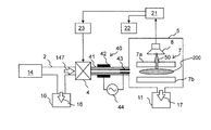
- FIG. 1A schematically shows a configuration example of the mass spectrometer of the present embodiment.
- a sample vaporization unit 14, a tube 2, an exhaust pump 10, a valve 4, an ion source 40, and an analysis chamber 5 are included.
- the tube 2 connects the sample vaporizing unit 14, the exhaust pump 10, and the valve 4.
- the ion source 40 includes a dielectric tube 41, an outer electrode 42, an inner electrode 43, and an AC power supply 44 for barrier discharge.
- the ion source 40 exists between the analysis chamber 5 and the valve 4.
- the analysis chamber 5 accommodates an ion trap 7 and a detector 8.
- the ion trap 7 has a linear ion trap quadrupole, and FIG. 1A shows only two electrodes 7a and 7b among the four electrodes.
- the exhaust pump 11 exhausts gas from the analysis chamber 5.
- a mass spectrometer, a control unit 21, an ion trap control power source 22, and a valve control power source 23 are included.
- the ion trap control power source 22 and the valve control power source 23 are power sources for controlling the linear ion trap quadrupole and the valve 4, respectively, and are controlled by the control unit 21.
- the control unit 21 controls mass spectrometry by controlling the operation of the components of the mass spectrometer.
- the control unit 21 may be configured by hardware by designing with an integrated circuit or the like, and the processor uses software by reading, interpreting, and executing a program that realizes each function from the memory. It may be realized.
- the sample vaporization unit 14 vaporizes a part of the sample.
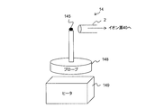
- FIG. 1B shows a configuration example of the sample vaporization unit 14.
- the sample vaporization unit 14 includes a probe 148 and a heater 149.
- the probe 148 vaporizes the sampled sample 145 at its tip.
- the vaporized sample gas is introduced into the ion source 40 from an inlet installed near the probe tip.
- the material of the probe 148 is a material having good heat resistance and thermal conductivity such as metal and ceramic.
- the probe 148 can be separated from the heater 149. For example, the user attaches the tip of the probe 148 to the sample (powder, solution, etc.) 145 and samples the sample 145.
- the tip of the probe 148 may have irregularities so that the sample 145 can be easily attached.
- the tip since the tip has a curved surface without having a sharp corner, it is possible to prevent the crystal of the sample 145 from adhering to the corner portion and the sample amount from fluctuating.
- the area of the tip is, for example, about 0.1 mm to 10 mm. The larger the tip area, the greater the amount of sample adhering to the probe 148 and the higher the sensitivity. On the other hand, the smaller the area of the tip, the less likely to be affected by contamination and carry-over due to contaminants.
- the distance between the portion of the probe 148 that contacts the heater 149 and the tip of the probe 148 is, for example, about 10 mm to 100 mm.
- the periphery of the probe 148 may be surrounded by a wall in order to avoid the updraft from being disturbed by the influence of the outside air flow.
- the control unit 21 can control the temperature of the heater 149.
- the control unit 21 may control the temperature based on the mass analysis result.
- the sample vaporized in the sample vaporization unit 14 is introduced to the front of the valve 4 by the exhaust pump 10.
- the vaporized sample is introduced into the ion source 40 by the exhaust pump 11 together with the surrounding gas.
- the exhaust direction of the exhaust pump 10 is indicated by an arrow 16, and a vaporized sample introduced into the ion source 40 is indicated by an arrow 147.
- the exhaust pumps 10 and 11 continue to operate.
- the configuration of the valve 4 is a configuration that can control the introduction and non-introduction of gas intermittently, such as a pinch valve and a slide valve. Thereby, exhaust with the small exhaust pumps 10 and 11 is attained, and a mass spectrometer can be reduced in size.
- the exhaust pump 10 may be omitted.
- the ion source 40 includes a dielectric tube 41 such as glass, ceramic, and plastic, an outer electrode 42, and an inner electrode 43.
- An outer electrode 42 is disposed outside the dielectric tube 41 and an inner electrode 43 is disposed inside.
- the barrier discharge AC power supply 44 applies a voltage having a frequency of 1 to 100 kHz and a potential of 2 to 5 kV between the inner electrode 43 and the outer electrode 42 to cause a dielectric barrier discharge in the dielectric tube 41.
- the ion source 40 introduces sample molecules vaporized into the discharge region, and generates sample ions.
- the ions (precursor ions) generated by the ion source 40 are introduced into the analysis chamber 5, and then the control unit 21 closes the valve 4.
- An ion trap 7 and a detector 8 are arranged in the analysis chamber 5.
- the exhaust pump 11 is, for example, a turbo molecular pump or an ion getter pump. An exhaust direction of the exhaust pump 11 is indicated by an arrow 17.
- the ions introduced into the analysis room are introduced into the ion trap 7 and trapped.
- the ions 200 are held in the ion trap 7.
- Ions (fragment ions) discharged from the ion trap 7 to the detector 8 are indicated by arrows 50.
- FIG. 1C schematically shows a configuration example of the linear ion trap 7.
- the ion trap 7 has a quadrupole rod electrode.
- r 0 represents the inscribed circle radius (m) of the ion trap quadrupole.
- the quadrupole rod electrode is composed of a rod pair consisting of opposing rods 7a and 7b and a rod pair consisting of opposing rods 7c and 7d.
- the ion trap control power supply 22 applies the trap RF voltage 19 so as to be in phase between the opposing rods and in reverse phase between adjacent rods.
- a trap RF voltage 19 having an amplitude of 0 to 5 kV (0 to peak) and a frequency of about 500 kHz to 5 MHz is used.
- the ion trap control power source 22 may apply to the quadrupole rod electrode a positive offset voltage when measuring positive ions and a negative offset voltage when measuring negative ions, in addition to the trap RF voltage 19. By applying this trap RF voltage 19, ions can be trapped in the space inside the ion trap 7.
- the ion trap control power source 22 applies the auxiliary AC voltage 18 in addition to the trap RF voltage 19 between the pair of opposing rod electrodes 7a and 7b.
- the auxiliary AC voltage 18 has, for example, a single frequency waveform with an amplitude of 0 to 50 V (0 to peak) and a frequency of about 5 kHz to 2 MHz, or a superimposed waveform of a plurality of frequency components.
- the auxiliary AC voltage 18 excites the translational motion of m / z ions resonating with the frequency of the auxiliary AC voltage 18 in a mass selective manner. Specifically, the translational motion of ions having a specific m / z can be excited in the direction between the rod electrodes to which the auxiliary AC voltage 18 is applied. In the trajectory of the excited ions, the moving distance (amplitude) in the auxiliary AC voltage direction increases.
- a slit 71 is formed in the rod electrode 7a to which the auxiliary AC voltage is applied. Ions excited by the auxiliary AC voltage 18 increase the movement distance between the rod electrodes 7a and 7b, pass through the slit 71, and are selectively ejected from the ion trap 7.
- the detector 8 detects ions that have passed through the slit 71.
- the rod electrode 7b also has a slit, and another detector that detects ions that have passed through the rod electrode 7b may be disposed.
- the auxiliary AC voltage 18 can selectively eject ions from the ion trap 7, and can excite and dissociate ions while holding the ions in the ion trap 7 as will be described later. .
- the amplitude of the auxiliary AC voltage for dissociating ions is smaller than the amplitude for discharging ions. Generation of fragment ions by ion dissociation will be described later.
- Ions ejected from the ion trap 7 in a mass selective manner are converted into electric signals by an electron multiplier, a multi-channel plate, or a detector 8 comprising a conversion dynode, scintillator, photomultiplier, etc., to the control unit 21. Sent.
- the control unit 21 accumulates the data acquired from the detector 8 and the analysis result thereof in the storage unit in the control unit 21.
- the control unit 21 can calculate m / z of ions detected by the detector 8 from the frequencies of the trap RF voltage 19 and the auxiliary AC voltage 18.
- m / z of ions detected by the detector 8 can be calculated from the frequencies of the trap RF voltage 19 and the auxiliary AC voltage 18.
- the ⁇ value is expressed by the following equation 1 with the angular frequency ⁇ (rad / s) of the auxiliary AC voltage 18 and the angular frequency ⁇ (rad / s) of the trap RF voltage 19.
- the ⁇ value is a parameter related to the resonance frequency. Furthermore, there is a unique relationship between the ⁇ value and the q value.
- the q value is a parameter indicating a stable trapping condition for ions.
- the q value can be calculated from the ⁇ value.
- the mass m (kg) of ions that are resonantly excited is calculated from the q value according to the following formula 2.
- e is the elementary electric charge
- V is the amplitude (V0 ⁇ peak) of the trap RF voltage.
- r 0 is the inscribed circle radius (m) of the ion trap quadrupole (see FIG. 1C).
- the mass spectrometer shown in FIG. 1A intermittently introduces the sample via the valve 4. Unlike this, as shown in FIG. 1D, the mass spectrometer may intermittently introduce ions from the ion source 40 operating at atmospheric pressure via the valve 4.
- the MSn measurement sequence of the present embodiment includes an accumulation step, an exhaust waiting step, an isolation step, a dissociation step, a mass scan step, and an exclusion step.
- the set of dissociation steps and mass scan steps is repeated for the sequentially selected precursor ions.
- sample ions are introduced into the analysis chamber 5.
- the exhaust waiting step waits until the pressure in the analysis chamber 5 is reduced to a pressure at which ions can be isolated and measured.
- the isolation step only precursor ions having specific different mass-to-charge ratios (m / z) are isolated from ions in the ion trap 7.
- ions of different m / z may be referred to as different types of ions.
- the dissociation step one or a plurality of precursor ions selected from the isolated precursor ions are dissociated to generate fragment ions.
- precursor ions ions before dissociation
- fragment ions ions after dissociation
- the generated fragment ions are ejected from the ion trap 7 to the detector 8 in a mass selective manner.
- the MSn measurement sequence of this example repeats a set of a dissociation step and a mass scan step to generate fragment ions from sequentially selected precursor ions and perform mass analysis of the generated fragment ions.
- ions remaining in the ion trap 7 are excluded after the MSn measurement is completed for all target precursor ions.
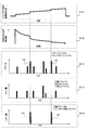
- FIG. 2A shows the operation of the valve 4, the pressure in the analysis chamber 5, the trap RF voltage, the auxiliary AC voltage, and the operation of the detector 8 in the MSn measurement sequence.
- FIG. 2B shows the relationship between the frequency and amplitude value of the auxiliary AC voltage in the isolation step.
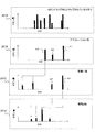
- FIG. 3 shows ions held by the ion trap 7 in the MSn measurement sequence.
- the control unit 21 opens the valve 4 to introduce the sample gas into the ion source 40. Thereafter, the control unit 21 closes the valve 4. Sample ions generated by the ion source 40 are introduced into the analysis chamber 5 and trapped in the ion trap 7.
- the pressure in the analysis chamber 5 is 1 Pa or more (for example, about 10 Pa) when the valve 4 is opened.
- the accumulation step time is, for example, about 10 ms to 1000 ms.
- a graph 251A indicates ions held in the ion trap 7 in the accumulation step.
- a plurality of m / z ions including the precursor ions to be analyzed are held in the ion trap 7.
- the control unit 21 stands by until the pressure in the analysis chamber 5 is reduced to a pressure of 0.1 Pa or less that enables ion isolation and measurement by the exhaust pump 11.
- the time for the exhaust waiting step is, for example, about 1000 ms to 10000 ms.
- the control unit 21 controls the ion trap control power source 22 to apply a superimposed waveform of a plurality of frequencies as the auxiliary AC voltage 18. This signal is called FNF (Filtered Noise Field).
- FNF Frtered Noise Field
- the FNF excludes other m / z ions from the ion trap 7 while holding only the specific m / z precursor ions in the ion trap 7 among the ions in the ion trap 7.
- By applying an appropriate FNF only the target precursor ions can be held in the ion trap 7 and other ions can be excluded from the ion trap 7. Isolation can be completed in a short time by FNF.
- FNF has a plurality of frequency components different from the resonance frequency component of the target precursor ion. FNF resonance-excites the translational motion of other ions different from the target precursor ion, and increases its movement distance. As a result, other ions are excluded from the ion trap 7.
- the highest frequency of FNF is, for example, half the trap RF voltage frequency.
- the lowest frequency is, for example, a frequency of about 1 to 20 kHz.
- the FNF has a frequency component between the lowest frequency and the highest frequency.
- the interval between the frequency components is, for example, about several Hz to several hundred Hz, and the phase difference between the frequency components is random. As the frequency component interval is wider and the total number of frequency components included in the FNF is smaller, resonance-excited ions can be eliminated with a smaller FNF voltage amplitude. On the other hand, if the frequency component interval is too wide, the efficiency of removing m / z ions having a resonance frequency in the gap between the frequency components included in the FNF is lowered.
- the neighborhood range can be defined by a predetermined threshold.
- the frequency component range that is removed in the FNF for isolation may be referred to as an isolation window.
- the control unit 21 makes the amplitude of the trap RF voltage larger than the amplitude in the accumulation step, the exhaust waiting step, and the dissociation step. This improves the isolation performance.
- the amplitude of the trap RF voltage may be constant, or the magnitude relationship of the amplitude of the trap RF voltage may be different from this example.
- a graph 251B shows an example of precursor ions held in the ion trap 7 after isolation.
- three different m / z precursor ions m 3, m 2, m 1 are held in the ion trap 7.
- FIG. 2B shows frequency components included in the FNF corresponding to the graph 251B.
- the frequency bands including the resonance frequency of the precursor ions m3, m2, and m1 and the nearby frequencies are the frequency bands ⁇ f1, ⁇ f2, and ⁇ f3, respectively.
- the control unit 21 applies FNF excluding the frequency bands ⁇ f1, ⁇ f2, and ⁇ f3, that is, FNF having notches in the frequency bands ⁇ f1, ⁇ f2, and ⁇ f3.
- FNF excluding the frequency bands ⁇ f1, ⁇ f2, and ⁇ f3, that is, FNF having notches in the frequency bands ⁇ f1, ⁇ f2, and ⁇ f3.
- a range in which the frequency is removed from the FNF such as the frequency bands ⁇ f1, ⁇ f2, and ⁇ f3, is also referred to as an isolation window.
- Each of the frequency bands ⁇ f1, ⁇ f2, and ⁇ f3 is an isolation window.
- the intensity of the frequency component included in the FNF may change depending on the frequency.
- the time of the isolation step is, for example, about 1 ms to 100 ms.
- the control unit 21 dissociates one or a plurality of different m / z precursor ions selected from the plurality of isolated precursor ions to generate fragment ions.
- a typical dissociation process time is about 1 ms to 100 ms.
- the controller 21 selectively dissociates the precursor ions into fragment ions by applying an auxiliary AC voltage including the resonance frequency of the target precursor ions.
- the control unit 21 can selectively dissociate the precursor ions m1 and m2 by applying an auxiliary AC voltage having peaks in the frequency bands ⁇ f1 and ⁇ f2.
- the amplitude value of the auxiliary AC voltage in dissociation is within a range where ions are not ejected from the ion trap 7, and is smaller than the amplitude value for ion exclusion and ejection in the isolation and mass scan.
- the trap RF voltage amplitude value in the dissociation step (dissociation 1, dissociation 2) is smaller than the values in the accumulation step and the disposal waiting step.
- the minimum m / z value of trapped ions is proportional to the trap RF voltage amplitude value.
- the pressure of the buffer gas that causes dissociation of ions by collision is, for example, about 0.01 Pa to 1 Pa.
- the buffer gas may be a gas remaining in the analysis chamber 5 or a gas separately introduced into the ion trap 7. By introducing the gas separately, the gas pressure can be controlled with high accuracy and measurement with high reproducibility can be performed.
- the control unit 21 dissociates one precursor ion m3 selected from the precursor ions m3, m2, and m1.
- a graph 251C shows ions held in the ion trap 7 after dissociating the precursor ions m3.
- Graph 251C shows fragment ions of precursor ion m3 and precursor ions m2 and m1.
- the control unit 21 After the dissociation step, the control unit 21 performs a fragment ion mass scanning step. In the mass scanning step, the control unit 21 holds the remaining precursor ions in the ion trap 7 and the fragment ions generated in the immediately preceding dissociation step to the detector 8 outside the ion trap 7 in a mass selective manner. Discharge towards. The detector 8 detects incoming ions.
- the control unit 21 mass-selectively discharges fragment ions generated from the precursor ions m3 to the outside of the ion trap 7. To do.
- the detector 8 detects and measures the discharged fragment ions.
- the time of the mass scan step is, for example, about 10 ms to 1000 ms.
- An example of the mass scanning method is to scan the trap RF voltage amplitude while applying an auxiliary AC voltage having a constant frequency. Another example scans the frequency of the auxiliary AC voltage while keeping the trap RF voltage amplitude constant.
- the resonance condition of the precursor ions held in the ion trap 7 is skipped, and scanning is performed intermittently. Thereby, precursor ions can be held in the ion trap 7. Further, by scanning, even when the mass charge cost m / z of the fragment ions is unknown, the fragment ions can be appropriately discharged.
- a graph 451A shows an example of the amplitude change of the trap RF voltage in the mass scan step.
- a graph 451B shows an example of the frequency change of the auxiliary AC voltage in the mass scanning step.
- the control unit 21 changes the trap RF voltage or the auxiliary AC voltage as in the graph 451A or the graph 451B.
- Graph 451C shows ions trapped in ion trap 7 at the start of the mass scan step.
- Graph 451D shows the fragment ions that are ejected in the mass scan step and detected by detector 8.
- Graph 451E shows precursor ions mA, mB remaining in ion trap 7 after the mass scan step.
- the control unit 21 gradually increases the trap RF voltage.
- the m / z of resonating ions increases with the trap RF voltage.
- the controller 21 skips the trap RF voltage value amplitude value corresponding to the precursor ions mA and mB to be maintained in the ion trap 7 in the change of the trap RF voltage amplitude. Thereby, it is avoided that the precursor ions mA and mB are ejected by the scanning of the trap RF voltage amplitude.
- the mass m of ions resonating with the frequency of the auxiliary AC voltage depends on the amplitude V of the trap RF voltage. Therefore, when the frequency of the auxiliary AC voltage is constant and the amplitude of the trap RF voltage changes, ions that resonate with the auxiliary AC voltage change.
- the controller 21 skips the amplitude value (resonance amplitude value) of the trap RF voltage at which the precursor ions mA and mB resonate with the auxiliary AC voltage. For example, the control unit 21 skips a predetermined range including the resonance amplitude values of the precursor ions mA and mB. The size of the range depends on the design.
- control unit 21 may gradually decrease the trap RF voltage in the scan of the trap RF voltage amplitude.
- the skipped amplitude value is the same as when the trap RF voltage amplitude gradually increases.
- the rate of change of the trap RF voltage may be constant or may change.
- the control unit 21 gradually decreases the frequency of the auxiliary AC voltage while maintaining the amplitude value of the trap RF voltage.
- the m / z of resonating ions increases with decreasing auxiliary AC voltage frequency.
- the controller 21 skips the auxiliary AC electric frequency at which the precursor ions mA and mB to be maintained in the ion trap 7 resonate in the frequency change of the auxiliary AC voltage. Thereby, it is avoided that the precursor ions mA and mB are discharged by the scan of the auxiliary AC voltage frequency.
- control unit 21 skips a predetermined range (two frequency bands) including the resonance frequencies of the precursor ions mA and mB.
- the size of the range depends on the design.
- the control unit 21 may gradually decrease the auxiliary AC voltage frequency in the scan of the auxiliary AC voltage frequency.
- the skipped amplitude value is the same as when the trap RF voltage amplitude gradually increases.
- the rate of change of the trap RF voltage may be constant or may change.
- the precursor from the mass scan range is skipped without performing skip in the scan Body ions can be excluded.
- the fragment ion when the precursor ion is a monovalent ion, the fragment ion has a smaller m / z than the original precursor ion. If the precursor ion having the smallest m / z is dissociated, in the ions held in the ion trap 7, the m / z of the fragment ions is smaller than the m / z of the other precursor ions.
- the control unit 21 performs mass scanning in a range where the upper limit of m / z in the mass scanning is less than m / z of the precursor ions. Thereby, even if mass scanning is continuously performed, fragment ions can be selectively ejected while the precursor ions are held in the ion trap. The same applies when dissociation and mass scanning are performed from precursor ions having a large m / z.
- the mass scanning step (mass scanning 1, 2) of this example scans the trap RF voltage amplitude.
- the controller 21 further increases the auxiliary AC voltage amplitude as the trap RF voltage amplitude increases. The greater the RF voltage amplitude, the deeper the potential for trapping ions. By increasing the auxiliary AC voltage amplitude as the trap RF voltage amplitude increases, fragment ions can be more appropriately discharged from the deep potential.
- the auxiliary AC voltage amplitude may be constant.
- the control unit 21 dissociates the precursor ions m2 and m1 remaining in the ion trap 7 (dissociation). 2) and a mass scanning step (mass scanning 2).
- the control unit 21 dissociates both the precursor ions m2 and m1 in the dissociation step (dissociation 2).
- a graph 251D shows fragment ions generated by dissociating precursor ions m2 and m1 in one dissociation step.
- the control unit 21 selectively ejects the fragment ions generated from both from the ion trap 7 in one mass scanning step, and detects them by the detector 8.
- one group is composed of a plurality of kinds of precursor ions having different m / z of fragment ions, and all precursor ions of the group are dissociated in one dissociation step.
- the precursor ion m3 a simpler MSn spectrum can be obtained by dissociating and mass-scanning a single kind of precursor ion, thereby improving selectivity.
- the control unit 21 repeats a set of a dissociation step and a mass scanning step for precursor ions sequentially selected from a plurality of types of precursor ions isolated in one isolation step. Thereby, MS2 spectra of all precursor ions isolated in one isolation step are acquired.
- the control unit 21 executes the exclusion step.
- the control unit 21 eliminates all ions remaining in the trap 7 by setting the voltage amplitude of the trap RF voltage to 0.
- a typical exclusion step time is about 1 ms to 100 ms.
- control unit 21 acquires MSn (n is an integer of 3 or more) spectrum by repeating dissociation while maintaining dissociation and holding ions in the ion trap 7. Can do.
- FIG. 5 shows an example of two-stage dissociation of the precursor ion m3 immediately after isolation.
- a graph 551A shows the precursor ions m3, m2, and m1 immediately after the isolation step.
- Graph 551B shows fragment ions after selectively dissociating precursor ion m3.
- Graph 551C shows fragment ions generated by selecting ions from the fragment ions of graph 551B and dissociating them as precursor ions.
- MSn measurement can be realized by performing multi-step dissociation.
- a plurality of types of precursor ions are isolated in one isolation step, and one or more types of precursor ion dissociation step and fragment ion mass scanning step that are sequentially selected I do.
- the MSn spectrum of a plurality of types of precursor ions can be appropriately measured in one accumulation, waiting for exhaustion, and isolation step, and measurement with high throughput and high selectivity becomes possible.
- MS / MS measurement is performed for each of 10 types of precursor ions under measurement conditions of an accumulation time of 30 ms, an exhaust waiting time of 1000 ms, an isolation time of 10 ms, a dissociation time of 10 ms, a mass scan time of 100 ms, and an exclusion time of 10 ms.
- a throughput five times or more that of the conventional method can be obtained.
- a great effect can be obtained when using intermittent introduction that requires an exhaust waiting time as in this embodiment. Since an MSn spectrum for each precursor ion can be obtained, identification and quantification can be performed with high accuracy even when the selectivity is high and the number of precursor ions is large.
- FIG. 6 shows another configuration example of the mass spectrometer.
- the introduction mechanism of buffer gas or the like is omitted for simplification.
- Ions generated by an ion source 101 such as an electrospray ion source, an atmospheric pressure chemical ion source, an atmospheric pressure photoion source, an atmospheric pressure matrix assisted laser desorption ion source, or a matrix assisted laser desorption ion source are the first pores 102. And is introduced into the first differential exhaust portion 105.
- the first differential exhaust unit 105 is exhausted by a pump 140.
- the ions introduced into the first differential exhaust part 105 are introduced into the second differential exhaust part 106 through the second pore 103.
- the second differential exhaust unit 106 is exhausted by the pump 141 and is maintained at a pressure of about 1.3 ⁇ 10 ⁇ 2 Pa to 1.3 Pa.
- An ion guide 131 is installed in the second differential exhaust unit 106.
- the ion guide 131 has a quadrupole rod electrode 110.
- the quadrupole rod electrode 110 is applied with an RF voltage with an inverted phase generated by an RF power source.
- the voltage amplitude of the RF voltage is, for example, several hundred to 5000 sV, and the frequency is about 500 kHz to 2 MHz.
- a quadrupole DC voltage may be applied to the quadrupole rod electrode 110 of the ion guide so that only m / z in the range scanned by the mass spectrum passes through the ion guide and is introduced into the ion trap. .
- the ions from the second differential exhaust unit 106 are introduced into the high vacuum chamber 107 through the third pore 104.
- the high vacuum chamber 107 is evacuated by a pump 142 and maintained at 0.1 Pa or less.
- a linear ion trap 132 and a detector 6 are installed in the high vacuum chamber 107.
- the structure of the linear ion trap is the same as that of the first embodiment. In the first embodiment, an example of a linear ion trap is described.
- the ion trap is an ion trap that selectively ejects ions from the trap and selectively measures a mass spectrum, such as a three-dimensional quadrupole ion trap or a toroidal ion trap
- the present invention can be applied to the mass spectrometer of the embodiment.
- Example 1 uses collision-induced dissociation, the mass spectrometer of the present invention can use other dissociation methods. For example, photoinduced dissociation may be used, for example.
- valve control is unnecessary as compared with the configuration of the first embodiment, and mass spectrometry can be performed with a simpler configuration and control.
- This embodiment uses a frequency scan of the auxiliary AC voltage instead of FNF in the isolation step.
- a method similar to the frequency scan of the auxiliary AC voltage in the mass scan step of Embodiment 1 can be applied.
- the controller 21 skips the precursor ion resonance frequency band, that is, the resonance frequency of the precursor ions and the frequency in the vicinity thereof, and scans the frequency of the auxiliary AC voltage, thereby scanning ions other than the precursor ions in the ion trap 7. To eliminate.
- the direction of scanning the frequency of the auxiliary AC voltage may be from the low mass side to the high mass side, or from the high mass side to the low mass side. However, in the case of scanning from the low mass side to the high mass side, when ions are dissociated by the auxiliary AC voltage to generate low mass fragment ions, the fragment ions remain in the ion trap 7.
- ion sources that generate monovalent ions such as atmospheric pressure chemical ionization, dielectric barrier discharge, electron impact ionization, atmospheric pressure matrix assisted laser desorption ion source, matrix assisted laser desorption ion source, etc. It is preferable to scan from the high mass side to the low mass side.
- the controller 21 may scan the amplitude of the trap RF voltage in the isolation step instead of the frequency scan of the auxiliary AC voltage.
- the same technique as the voltage scan of the trap RF voltage in the mass scan step of the first embodiment can be applied.
- the scan direction is as described above for the frequency scan of the auxiliary AC voltage.
- the frequency band of the auxiliary AC voltage to be skipped and the amplitude width of the trap RF voltage may be referred to as an isolation window.
- This example describes a method for reducing the effect of space charge on isolation.
- the points other than the isolation method are the same as in the first embodiment.
- the resonance frequency of ions shifts to a lower frequency side due to space charge.
- the resonance frequency of the precursor ion to be measured shifts to the lower frequency side due to the influence of space charge and enters the range excited by FNF, the precursor ion to be maintained in the ion trap is eliminated by FNF, Efficiency.
- One method for reducing the decrease in isolation efficiency due to space charge is to sequentially apply FNFs having different isolation window widths.
- the isolation window is a frequency component range that is removed in the FNF.
- the control unit 21 applies FNF having a wide isolation window (for example, about 5 to 20 Da).
- the widths of the plurality of isolation windows in the FNF are the same or different.
- the isolation window is wide, even if the resonance frequency of the precursor ions is shifted due to space charge, the ions to be isolated are located in the isolation window.
- the isolation window is wide, even if the resonance frequency of the precursor ions is shifted due to space charge, the ions to be isolated are located in the isolation window.
- control unit 21 performs isolation by applying FNF having an isolation window (for example, 1 to 3 Da) narrower than the previous time.
- FNF having an isolation window (for example, 1 to 3 Da) narrower than the previous time.
- the isolation width of the actually isolated ion represented by the unified atomic mass unit Da depends on the m / z, q value, etc. of the target precursor ion. Therefore, even if the width of the isolation window represented by the frequency (the width of the frequency band excluded from FNF) is the same, the isolation width of ions that are actually isolated is different.
- the width of the frequency band (isolation window) to be removed from the FNF is such that the m / z of the ion to be isolated is small (q value is high). It is wide in the case, and narrow when the m / z of the ion to be isolated is large (q value is low). That is, the width of the isolation window is wider as the mass-to-charge ratio of the precursor ions is smaller.
- the frequency range to be removed from the FNF is determined by the method described below.
- ⁇ m l and ⁇ m h are ranges of the mass to charge ratio.
- the q value of the ion a at the isolation trap RF voltage amplitude V is q ′
- the q value of the ion corresponding to the low mass side end of the isolation window is q l
- the high value side end of the isolation window is corresponding to the high mass side end.
- the q value of the ion and the q h are determined so as to satisfy the following relationship.
- the frequency range that is converted into the frequency and removed from the FNF is determined.
- Isolation can be performed with an isolation width of ⁇ m h on the high mass side.
- the frequency edge of each isolation window of FNF is determined so that all isolation widths are the same in atomic mass units.
- the control unit 21 holds preset information such as m a of the ion a, the low mass side ⁇ m l , the high mass side ⁇ m h , the relationship between the ⁇ value and the q value, and from these, the above method is used.
- the value of the frequency component excluded from the FNF can be calculated.
- the waveform information of the FNF held by the control unit 21 indicates the frequency position of the isolation window determined by the above method.
- the method scans the trap RF voltage amplitude while applying FNF with a wide isolation window.
- FIG. 7 schematically shows the trap RF voltage amplitude and the isolation window at each step in the isolation using this method.
- the control unit 1 may apply FNF having an isolation window for each type of ions and perform the following processing on all the ions simultaneously.
- the control unit 21 applies FNF having a wide isolation width (about 5 to 20 Da) so that the resonance frequency of the precursor ion mC is near the center of the iris window. By applying this waveform, the total amount of ions in the ion trap 7 is reduced, and the space charge is reduced.
- the control unit 21 gradually increases (scans) the trap RF voltage amplitude while applying FNF.
- the resonance frequency of the ions depends on the trap RF voltage amplitude (Equation 2), by scanning the trap RF voltage amplitude until the resonance frequency of the precursor ion mC is close to the high frequency side end of the isolation window, Ions that are on the lower mass side than the precursor ion mC can be excluded.
- the controller 21 gradually decreases the trap RF voltage amplitude.
- the control unit 21 further gradually decreases (scans) the trap RF voltage amplitude until the resonance frequency of the precursor ion mC is close to the low frequency side end of the isolation window, and moves it toward the high mass side of the precursor ion. Eliminate certain ions.
- the frequency width to be removed from FNF is set to m / z of the ion to be isolated. It is set wide when z is small (q value is high) and narrow when m / z of the ion to be isolated is large (q value is low). That is, the width of the isolation window is wider as the mass-to-charge ratio of the precursor ions is smaller.
- the difference between the q value of the low frequency side end of the isolation window for isolating the ions b and the q value of the high mass side end (m b + Dm) of ions held in the ion trap 7 is expressed as ⁇ q b
- the q value corresponding to the low frequency side end of the FNF window is determined so as to satisfy the following relationship.
- the q value of the high frequency side end of the isolation window for isolating the ion a and the low mass side end (m a ⁇ Dm ′) of the ion held in the ion trap Let the difference be Dq a ′.
- a difference in q value between the high frequency side end of the isolation window for isolating the ion b and the low mass side end (m b -Dm ′) of the ion held in the ion trap is represented by ⁇ q b ′.
- the q value corresponding to the high frequency side end of the FNF window is determined so as to satisfy the following relationship.
- the trap RF voltage amplitude is scanned while applying the FNF.
- the ions a and b can be isolated with the same isolation width (Dm + Dm ′).
- the frequency edge of each isolation window of the FNF is determined so that all the isolation widths are the same in the unitary atomic mass unit.
- the control unit 21 holds information such as the mass-to-charge ratio of the ions a and b, Dm, Dm ′, and the relationship between ⁇ and q, and can calculate the value of the frequency component excluded from the FNF by using the above method.
- the waveform information of the FNF held by the control unit 21 indicates the frequency position of the isolation window determined by the above method.
- the above example determines the frequency of the isolation window in the FNF, but the above method can also be applied to the determination of the isolation window in the frequency scan of the auxiliary voltage and the amplitude scan of the trap RF voltage. As described above, in this example, the loss of precursor ions due to the influence of space charge can be suppressed in isolation.
- the amounts of precursor ions having different predetermined m / z are respectively measured, and precursor ions whose measured values exceed a threshold value are selectively subjected to mass spectrometry.
- precursor ions whose measured values exceed a threshold value are selectively subjected to mass spectrometry.
- the controller 21 first isolates specific precursor ions using FNF and measures their mass spectrum (MS1 spectrum). After the isolation of the precursor ions by FNF, the control unit 21 performs a mass scan of the precursor ions without dissociating any precursor ions. As a result, an MS1 spectrum consisting only of precursor ions is obtained.
- control unit 21 selects a precursor ion whose precursor ion signal intensity (ion amount) exceeds a threshold in the MS1 spectrum as a measurement target.
- the control unit 21 isolates the selected precursor ion for MSn measurement.
- the combination of precursor ions to be measured by MSn varies depending on the measurement result of the MS1 spectrum. That is, the m / z of the precursor ion to be isolated is not determined before the MS1 measurement.
- One method performs isolation using a frequency scan of the auxiliary AC voltage as described in the third embodiment.
- the control unit 21 scans the frequency of the auxiliary AC voltage while skipping the frequency band corresponding to m / z of the precursor ion exceeding the threshold in the MS1 spectrum.
- the control unit 21 may scan the amplitude of the RF trap voltage.
- an FNF having an isolation window corresponding to all of the assumed precursor ions is generated in advance, and a single frequency auxiliary AC voltage is applied simultaneously with the application of the FNF.
- the control unit 21 scans the frequency of the auxiliary AC voltage within the range of the isolation window other than the precursor ion to be measured. This method enables isolation faster than the frequency scan of the auxiliary AC voltage described in Embodiment 3, and can also suppress the influence of space charge.
- FIG. 8 schematically shows the generation of the FNF.
- the control unit 21 generates an FNF original waveform 851 that does not have an isolation window in advance using an inverse fast Fourier transform or the like, and stores it in a memory. Specifically, the control unit 21 stores the phase and intensity information 852 of each frequency component of the FNF original waveform in a table in the memory.
- the control unit 21 holds in advance the resonance frequency values of all precursor ions to be measured for MS1.
- the control unit 21 identifies the precursor ions to be measured for MSn from the MS1 spectrum and identifies their resonance frequencies.
- the control unit 21 refers to the table information 852, and generates the frequency component 853 of the resonance frequency band (resonance frequency and their neighboring frequencies) of the precursor ion to be measured by generating a digital waveform or the like. Are generated with the opposite phase and the same intensity as the frequency component included in the original waveform.
- the control unit 21 adds the time-domain FNF original waveform 851 and the digital waveform generated waveform 853 for each output unit time, and outputs the result as an auxiliary AC voltage 854. By this operation, the frequency component around the resonance frequency of the precursor ion of the measurement target of the original waveform of FNF is canceled, so that the combination of the precursor ions of the measurement target can be isolated.
- this invention is not limited to the above-mentioned Example, Various modifications are included.
- the above-described embodiments have been described in detail for easy understanding of the present invention, and are not necessarily limited to those having all the configurations described.
- a part of the configuration of one embodiment can be replaced with the configuration of another embodiment, and the configuration of another embodiment can be added to the configuration of one embodiment.
- each of the above-described configurations, functions, processing units, etc. may be realized in hardware by designing a part or all of them, for example, with an integrated circuit.
- each of the above-described configurations, functions, and the like may be realized using software by causing a processor to interpret and execute a program that realizes each function.
- Information such as programs, tables, and files for realizing each function can be stored in a memory, a hard disk, a recording device such as an SSD (Solid State Drive), or a recording medium such as an IC card or an SD card.
- control lines and information lines are those that are considered necessary for the explanation, and not all the control lines and information lines on the product are necessarily shown. In practice, it may be considered that almost all the components are connected to each other.
Landscapes
- Chemical & Material Sciences (AREA)
- Analytical Chemistry (AREA)
- Other Investigation Or Analysis Of Materials By Electrical Means (AREA)
- Electron Tubes For Measurement (AREA)
Abstract
質量分析方法は、RF電圧と共に補助交流電圧を印加して、異なる質量電荷比を有する異なる種類の前駆体イオンをイオントラップ内に保持しつつ、補助交流電圧に共鳴する他のイオンをイオントラップから排除する。異なる種類の前駆体イオンの1又は複数種類の前駆体イオンを選択し、非選択前駆体イオンをイオントラップ内に保持しつつ、選択した前駆体イオンを補助交流電圧との共鳴により解離させてフラグメントイオンを生成する。非選択前駆体イオンをイオントラップ内に保持しつつ、生成したフラグメントイオンを補助交流電圧との共鳴によりイオントラップから排出して検出する。解離と排出とを繰り返し、異なる種類の前駆体イオンの質量測定を行う。
Description
本出願は、2013年6月27日に出願された日本出願である特願2013-134800の優先権を主張し、その内容を参照することにより、本出願に取り込む。
本発明は質量分析に関する。
特許文献1は、複数の前駆体イオンを同時にアイソレーションし、アイソレーションした複数の前駆体イオンを同時に解離させて、生成したフラグメントイオンのMS/MSスペクトルを取得する方法を開示している。
特許文献1に記載の方法は、MS/MS質量分析を高スループットで行うことができる。しかし、当該方法は、アイソレーションした複数の前駆体イオンを同時に解離させるため、各フラグメントイオンがどの前駆体イオンから生成したかという情報を失う。そのため、特に、複数の前駆体イオンが、同じ質量電荷比(m/z)のフラグメントイオンを生成する場合に、フラグメントイオンを生成した前駆体イオンを特定することができない。また、アイソレートする前駆体イオンの数が多いほど、MS/MSスペクトルが複雑になり、試料の定量や同定が困難になる。
本発明の一態様の質量分析方法は、試料をイオン源においてイオン化する、イオン化ステップと、前記イオン源で生成されたイオンを、RF電圧を使用してイオントラップにトラップする、トラッピングステップと、前記イオントラップに前記RF電圧と共に補助交流電圧を印加して、異なる質量電荷比を有する異なる種類の前駆体イオンを前記イオントラップ内に保持しつつ、前記補助交流電圧に共鳴する他のイオンを前記イオントラップから排除して、前記異なる種類の前駆体イオンをアイソレートする、アイソレーションステップと、前記異なる種類の前駆体イオンの1又は複数種類の前駆体イオンを選択し、前記選択した前駆体イオン以外の非選択前駆体イオンを前記イオントラップ内に保持しつつ、前記選択した前駆体イオンを前記補助交流電圧との共鳴により解離させてフラグメントイオンを生成する、解離ステップと、前記非選択前駆体イオンを前記イオントラップ内に保持しつつ、前記生成したフラグメントイオンを前記補助交流電圧との共鳴により前記イオントラップから排出して検出器において検出する、排出ステップと、を含み、前記解離ステップと前記排出ステップとを繰り返し、前記異なる種類の前駆体イオンの質量測定を行う。
本発明の一態様によれば、高スループットでかつ、選択性が高いMSn測定を行うことができる。
以下、添付図面を参照して本発明の実施形態を説明する。本実施形態は本発明を実現するための一例に過ぎず、本発明の技術的範囲を限定するものではないことに注意すべきである。各図において共通の構成については同一の参照符号が付されている。
本実施形態は、RF電圧と補助交流電圧を使用した、イオンの質量分析を説明する。本実施形態の質量分析装置は、イオントラップにおいて試料イオンをトラップし、それらから特定質量電荷比の前駆体イオンをアイソレートする。質量分析装置は、アイソレートした前駆体イオンから選択した1又は複数の質量電荷比の前駆体イオンを解離してフラグメントイオンを生成し、イオントラップから検出器に排出する。質量分析装置は、上記解離と当該解離により生成したフラグメントイオンの検出(測定)を繰り返す。
本実施形態の質量分析により、1回のアイソレーションでアイソレートした前駆体イオンの解離と検出を繰り返すことで、高スループットで選択性が高い測定が可能になる。
図1Aは、本実施例の質量分析装置の構成例を模式的に示す。試料気化部14、管2、排気ポンプ10、バルブ4、イオン源40、分析室5を含む。管2は、試料気化部14、排気ポンプ10、バルブ4を接続する。イオン源40は、誘電体管41、外側電極42、内側電極43、バリア放電用交流電源44を含む。イオン源40は、分析室5とバルブ4との間に存在する。
分析室5は、イオントラップ7及び検出器8を収容する。図1Aの例において、イオントラップ7は、リニアイオントラップ四重極を有し、図1Aは、四つの電極のうち、二つの電極7a、7bのみを示す。
排気ポンプ11は、分析室5から気体を排気する。質量分析装置、制御部21、イオントラップ制御電源22、バルブ制御電源23を含む。イオントラップ制御電源22、バルブ制御電源23は、それぞれ、リニアイオントラップ四重極、バルブ4を制御する電源であり、制御部21に制御される。
制御部21は、質量分析装置の構成要素の動作を制御することで、質量分析を制御する。制御部21は、集積回路で設計する等によりハードウェアで構成されていてもよいし、プロセッサがそれぞれの機能を実現するプログラムをメモリから読み出して解釈し、実行することにより、ソフトウェアを使用して実現してもよい。
試料気化部14は、試料の一部を気化する。図1Bは、試料気化部14の構成例を示す。試料気化部14はプローブ148とヒータ149を含む。プローブ148は、その先端において、サンプリングされた試料145を気化させる。
気化した試料ガスは、プローブ先端近傍に設置した入口からイオン源40へ導入される。プローブ148の材質は、金属やセラミックなどの耐熱性、熱伝導性がよい素材である。プローブ148は、ヒータ149から分離可能であり、例えば、ユーザは、プローブ148の先端を試料(粉末、溶液など)145につけて、試料145をサンプリングする。
プローブ148の先端は、試料145を付着させやすいように、凹凸を持っていてもよい。また、逆に先端が、鋭い角を有することなく、曲面であることで、試料145の結晶などが角の部分に付着して試料量が変動するのを抑制できる。先端部の面積は、例えば、0.1mm~10mm程度である。先端部の面積が大きいほどプローブ148に付着する試料の量が多くなり感度は高くなる。一方、先端部の面積が小さい程、夾雑物により汚染やキャリーオーバーの影響を受けにくくなる。
プローブ148のヒータ149と接触する部分と、プローブ148の先端との距離は、例えば、10mm~100mm程度である。プローブ148のヒータ149と接触する部分とプローブ148の先端との距離が短いほど、プローブ148の先端に熱伝導の効率が上がる。プローブ148のヒータ149と接触する部分とプローブ148の先端との距離が長いほど、ヒータ149と接触する部分に試料や夾雑物が付着する可能性を小さくすることができる。ヒータ149の上にプローブ148を載せるような構成とすると、ヒータ149で加熱された空気が上昇気流を形成するため、試料145を装置の入口近くに効率的に運ぶことができる。
この際、外気のながれの影響で上昇気流が乱されるのを避けるため、プローブ148の周辺を壁で囲んでもよい。プローブ148の付け根の面積を大きくすると、ヒータ149との接触面積を大きくとることができ、ヒータ149からの熱伝導効率がよくなる。制御部21は、ヒータ149の温度を制御することができる。制御部21は、質量分析結果をもとに温度を制御してもよい。
図1Aに戻って、試料気化部14において気化された試料は、排気ポンプ10によってバルブ4の手前まで導入される。バルブ4が開の時、気化された試料は、周辺ガスと共に、排気ポンプ11によって、イオン源40へ導入される。排気ポンプ10の排気方向は、矢印16で示され、イオン源40へ導入される気化試料が矢印147で示されている。排気ポンプ10、11は動作し続ける。
バルブ4の構成は、例えば、ピンチバルブ、スライドバルブのように、間欠的にガスの導入、非導入を制御できる構成である。これにより、小型の排気ポンプ10、11での排気が可能となり、質量分析装置を小型化できる。排気ポンプ10は省略してもよい。
イオン源40は、ガラス、セラミック、プラスティックなどの誘電体管41、外側電極42、内側電極43を有する。誘電体管41の外側に、外側電極42、内側には内側電極43が配置されている。バリア放電用交流電源44は、内側電極43と外側電極42との間に、周波数1~100kHz、電位2~5kV程度の電圧を印加して、誘電体管41内で誘電体バリア放電を起こす。イオン源40は、放電領域に気化された試料分子を導入し、試料イオンを生成する。
イオン源40で生成されたイオン(前駆体イオン)は、分析室5へ導入され、その後、制御部21は、バルブ4を閉じる。分析室5には、イオントラップ7及び検出器8が配置されている。排気ポンプ11は、例えば、ターボ分子ポンプやイオンゲッタポンプである。排気ポンプ11の排気方向方は、矢印17で示されている。
分析室に導入されたイオンはイオントラップ7に導入され、トラップされる。図1Aにおいて、イオン200は、イオントラップ7内で保持されている。イオントラップ7から検出器8へ排出されるイオン(フラグメントイオン)は、矢印50で示されている。
実施例1は、リニアイオントラップを、イオントラップ7の例として説明する。図1Cは、リニアイオントラップ7の構成例を模式的に示す。イオントラップ7は、四重極ロッド電極を有する。r0は、イオントラップ四重極の、内接円半径(m)を示す。
四重極ロッド電極は、対向するロッド7a、7bからなるロッド対と、対向するロッド7c、7d間からなるロッド対で構成されている。イオントラップ制御電源22は、対向ロッド間同相で、隣接ロッド間で逆相になるようにトラップRF電圧19を印加する。トラップRF電圧19は、例えば振幅0~5kV(0~peak)、周波数500kHz~5MHz程度のものが使用される。
イオントラップ制御電源22は、四重極ロッド電極に、トラップRF電圧19に加えて、正イオンを測定する場合は正の、負イオンを測定する場合には負のオフセット電圧を加えてもよい。このトラップRF電圧19を印加することで、イオントラップ7内部の空間にイオンをトラップすることが可能である。
さらに、イオントラップ制御電源22は、対向する一対のロッド電極7a、7b間に、トラップRF電圧19に加えて、補助交流電圧18を印加する。補助交流電圧18は、例えば、振幅0~50V(0~peak)、周波数5kHz~2MHz程度の単一周波数の波形、又は、複数周波数成分の重畳波形を有する。
補助交流電圧18は、補助交流電圧18の周波数に共鳴するm/zのイオンの並進運動を、質量選択的に励起する。具体的には、補助交流電圧18が印加されているロッド電極間方向において、特定のm/zを有するイオンの並進運動を、励起することができる。励起されたイオンの軌道において、補助交流電圧方向における移動距離(振幅)は増加する。
図1Cの例において、補助交流電圧を印加するロッド電極7aには、スリット71が形成されている。補助交流電圧18により励起されたイオンは、ロッド電極7a、7b間において移動距離を増加させ、スリット71を通って、イオントラップ7から質量選択的に排出される。検出器8は、スリット71を通過したイオンを検出する。なお、ロッド電極7bもスリットを有し、さらに、ロッド電極7bを通過したイオンを検出する他の検出器が配置されていてもよい。
補助交流電圧18は、イオントラップ7からイオンを質量選択的に排出することができるほか、後述するように、イオンをイオントラップ7内に保持したまま、イオンを励起させて、解離させることができる。イオンを解離させるための補助交流電圧の振幅は、イオンを排出するための振幅よりも小さい。イオンの解離によるフラグメントイオンの生成については後述する。
イオントラップ7から質量選択的に排出されたイオンは、電子増倍管、マルチチャンネルプレート、もしくはコンバージョンダイノードとシンチレータとフォトマルなどからなる検出器8により電気的な信号に変換され、制御部21へと送られる。制御部21は、検出器8から取得したデータ及びその解析結果を、制御部21内の記憶部に蓄積する。
制御部21は、検出器8が検出したイオンのm/zを、トラップRF電圧19及び補助交流電圧18の周波数から算出することができる。一例として、補助交流電圧18の周波数と、その補助交流電圧18の周波数で共鳴励起される一価イオンの質量の関係を説明する。β値は、補助交流電圧18の角周波数ω(rad/s)と、トラップRF電圧19の角周波数Ω(rad/s)とで、下記数1のようにあらわされる。

このように、β値は、共鳴周波数に関連したパラメータである。さらに、β値とq値との間には、一意な関係がある。q値は、イオンの安定捕捉条件を示すパラメータである。β値からq値を算出することができる。共鳴励起されるイオンの質量m(kg)は、q値から下記数2で算出される。eは電気素量、VはトラップRF電圧の振幅(V0-peak)である。r0は、イオントラップ四重極の内接円半径(m)である(図1C参照)。

図1Aの質量分析装置は、バルブ4を介して試料を間欠的に導入する。これと異なり、図1Dに示すように、質量分析装置は、大気圧で動作するイオン源40からバルブ4を介してイオンを間欠的に導入してもよい。
以下において、本実施例のMSn測定シーケンスの一例を説明する。本実施例のMSn測定シーケンスは、蓄積ステップ、排気待ちステップ、アイソレーションステップ、解離ステップ、質量スキャンステップ、排除ステップを有する。解離ステップ及び質量スキャンステップの組は、順次選択された前駆体イオンのために繰り返される。
蓄積ステップは、試料イオンを分析室5に導入する。排気待ちステップは、分析室5の圧力が、イオンをアイソレーション・測定できる圧力に減圧されるまで待機する。アイソレーションステップは、イオントラップ7内のイオンから、特定の異なる質量電荷比(m/z)の前駆体イオンのみをアイソレートする。以下では、異なるm/zのイオンを、異なる種類のイオンと呼ぶことがある。
解離ステップは、アイソレートした前駆体イオンから選択した1又は複数前駆体イオンを解離して、フラグメントイオンを生成する。本明細書において、解離前のイオンを前駆体イオンと呼び、解離後のイオンをフラグメントイオンと呼ぶ。質量スキャンステップは、生成されたフラグメントイオンを質量選択的に、イオントラップ7から検出器8に排出する。
本実施例のMSn測定シーケンスは、解離ステップと質量スキャンステップの組を繰り返して、順次選択した前駆体イオンからのフラグメントイオンの生成及び生成したフラグメントイオンの質量分析を行う。排除ステップは、全ての対象とする前駆体イオンについてMSn測定を終了した後に、イオントラップ7内に残るイオンを排除する。
以下、本実施例のMSn測定シーケンスの各ステップの詳細を、図2A、2B及び図3を参照して説明する。図2Aは、MSn測定シーケンスにおける、バルブ4の動作、分析室5の室内圧力、トラップRF電圧、補助交流電圧、検出器8の動作を示す。図2Bは、アイソレーションステップにおける、補助交流電圧の周波数と振幅値との関係を示す。図3は、MSn測定シーケンスにおいて、イオントラップ7が保持しているイオンを示す。
図2Aに示すように、蓄積ステップにおいて、制御部21は、バルブ4を開いて試料ガスをイオン源40に導入する。制御部21は、その後、バルブ4を閉じる。イオン源40で生成された試料イオンは、分析室5に導入され、イオントラップ7内にトラップされる。分析室5の圧力はバルブ4が開のときには、1Pa以上(例えば10Pa程度)である。蓄積ステップの時間は、例えば、10ms~1000ms程度である。
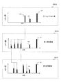
図3において、グラフ251Aは、蓄積ステップにおいてイオントラップ7に保持されているイオンを示している。分析対象の前駆体イオンを含む複数m/zのイオンがイオントラップ7に保持されている。
次に、排気待ちステップにおいて、制御部21は、排気ポンプ11によって、分析室5の圧力がイオンのアイソレーション・測定が可能となる0.1Pa以下の圧力に減圧されるまで待機する。蓄積ステップで導入される試料ガスが多いほど感度は向上し、試料ガスが少ないほど排気待ち時間は短くなりスループットは向上する。排気待ちステップの時間は、例えば、1000ms~10000ms程度である。
図2Aに示すように、アイソレーションステップにおいて、制御部21は、イオントラップ制御電源22を制御して、複数周波数の重畳波形を補助交流電圧18として印加する。この信号は、FNF(Filtered Noise Field)と呼ばれる。
FNFは、イオントラップ7内のイオンのうち、特定のm/zの前駆体イオンのみをイオントラップ7に保持したまま、他のm/zのイオンをイオントラップ7の外に排除する。適切なFNFを印加することで、目的とする前駆体イオンのみをイオントラップ7内に保持し、他のイオンをイオントラップ7外へ排除することができる。FNFにより、短時間にアイソレーションを完了できる。
具体的には、FNFは、目的とする前駆体イオンの共鳴周波数成分と異なる複数周波数成分を有する。FNFは、目的とする前駆体イオンと異なる他のイオンの並進運動を共鳴励起し、その移動距離を増加させる。これにより、他のイオンをイオントラップ7外へ排除する。
FNFの最高周波数は、例えば、トラップRF電圧周波数の半分の周波数である。最低周波数は、例えば、1~20kHz程度の周波数である。FNFは、最低周波数から最高周波数の間の周波数成分を有する。
各周波数成分の間隔は、例えば数Hz~数百Hz程度で、周波数成分間の位相差はランダムである。周波数成分の間隔が広くFNFに含まれる周波数成分の総数が少ないほど、小さいFNF電圧振幅で、共鳴励起されたイオンを排除できる。一方で、周波数成分の間隔が広すぎると、FNFに含まれる周波数成分の間隙に共鳴周波数をもつm/zのイオンの排除効率が低下する。
特定の前駆体イオンの共鳴周波数及びその近傍の周波数成分を除いたFNFを印加することで、特定の前駆体イオンをトラップ内に保持したまま、他のm/zのイオンを排除することができる。近傍範囲は、所定閾値で定義できる。本明細書において、アイソレーションのためにFNFにおいて除かれている周波数成分範囲をアイソレーション窓と呼ぶことがある。
図2Aにおいて、制御部21は、アイソレーションステップにおいて、トラップRF電圧の振幅を、蓄積ステップ、排気待ちステップ及び解離ステップにおける振幅よりも大きくする。これにより、アイソレーションの性能を向上させる。これらのステップにおいて、トラップRF電圧の振幅は一定でもよいし、トラップRF電圧の振幅の大小関係が本例と異なっていてもよい。
図3において、グラフ251Bは、アイソレーション後にイオントラップ7に保持されている前駆体イオンの例を示している。この例において、三つの異なるm/zの前駆体イオンm3、m2、m1が、イオントラップ7内に保持されている。
図2Bは、グラフ251Bに対応するFNFに含まれる周波数成分を示す。前駆体イオンm3、m2、m1の共鳴周波数及び近傍の周波数を含む周波数帯は、それぞれ、周波数帯Δf1、Δf2、Δf3である。制御部21は、周波数帯Δf1、Δf2、Δf3を除いたFNF、つまり、周波数帯Δf1、Δf2、Δf3のノッチを有するFNFを印加する。これにより、図3におけるグラフ251Aが示すトラップイオンから、前駆体イオンm3、m2、m1を除く他の全てのイオンを、イオントラップ7から排除することができる。
前駆体イオンの共鳴周波数を含む周波数帯を広くするほど、FNFで排除されずトラップ7内に保持されるイオンのm/zの範囲(アイソレーション幅)も広くなる。以下、周波数帯Δf1、Δf2、Δf3のように、FNFから周波数が除かれている範囲を、アイソレーション窓とも呼ぶ。周波数帯Δf1、Δf2、Δf3は、それぞれ、アイソレーション窓である。なお、FNFに含まれる周波数成分の強度は周波数に依存して変化していてもよい。アイソレーションステップの時間は、例えば、1ms~100ms程度である。
次に、解離ステップにおいて、制御部21は、アイソレートした複数の前駆体イオンから選択した1又は複数の異なるm/zの前駆体イオンを解離してフラグメントイオンを生成する。典型的な解離工程の時間は1ms~100ms程度である。制御部21は、目的とする前駆体イオンの共鳴周波数を含む補助交流電圧を印加することで、その前駆体イオンを選択的に、フラグメントイオンに解離させる。例えば、制御部21は、周波数帯Δf1及びΔf2のピークを有する補助交流電圧を印加して、前駆体イオンm1及びm2を選択的に解離させることができる。
解離における補助交流電圧の振幅値は、イオンをイオントラップ7から排出しない範囲内であり、アイソレーション及び質量スキャンにおけるイオン排除及び排出のための振幅値よりも小さい。
図2Aの例において、解離ステップ(解離1、解離2)におけるトラップRF電圧振幅値は、蓄積ステップ及び廃棄待ちステップにおける値より小さい。トラップされるイオンのm/zの最低値は、トラップRF電圧振幅値に比例する。トラップRF電圧振幅値を大きくすることで、生成されたフラグメントイオンがイオントラップ7から排除されることをより確実に防ぐことができる。解離ステップにおけるトラップRF電圧振幅値を小さくするか否かは、フラグメントイオンのm/zに依存する。
衝突によりイオンの解離を引き起こすバッファガスの圧力は、例えば、0.01Paから1Pa程度である。バッファガスは、分析室5に残留しているガスでもよいし、イオントラップ7に別途導入されたガスでもよい。別途ガスを導入することで、ガス圧力を精度良くコントロールし、再現性の高い測定を行うことができる。
例えば、図2Aにおいて、アイソレーションステップの直後の解離ステップ(解離1)において、制御部21は、前駆体イオンm3、m2、m1から選択した一つの前駆体イオンm3を解離させる。図3において、グラフ251Cは、前駆体イオンm3を解離させた後にイオントラップ7に保持されているイオンを示す。グラフ251Cは、前駆体イオンm3のフラグメントイオン及び前駆体イオンm2、m1を示している。
解離ステップの後、制御部21は、フラグメントイオンの質量スキャンステップを行う。質量スキャンステップにおいて、制御部21は、残っている前駆体イオンをイオントラップ7内に保持したまま、直前の解離ステップで生成したフラグメントイオンを、質量選択的にイオントラップ7外の検出器8に向けて排出する。検出器8は、飛来したイオンを検出する。
図2Aにおいて、解離ステップ(解離1)の直後の質量スキャンステップ(質量スキャン1)において、制御部21は、前駆体イオンm3から生成されたフラグメントイオンを質量選択的にイオントラップ7の外部に排出する。検出器8は、排出されたフラグメントイオンを検出、測定する。質量スキャンステップの時間は、例えば、10ms~1000ms程度である。
質量スキャンの方法の一例は、一定周波数の補助交流電圧を印加しながらトラップRF電圧振幅をスキャンする。他の例は、トラップRF電圧振幅を一定の維持しつつ、補助交流電圧の周波数をスキャンする。いずれの質量スキャン方法も、イオントラップ7中に保持されている前駆体イオンの共鳴条件をスキップして、断続的にスキャンを行う。これにより、前駆体イオンをイオントラップ7中に保持することができる。また、スキャニングにより、フラグメントイオンの質量電荷費m/zが不明の場合にも、適切にフラグメントイオンを排出できる。
図4を参照して、質量スキャン方法を説明する。図4において、グラフ451Aは、質量スキャンステップにおけるトラップRF電圧の振幅変化の一例を示す。グラフ451Bは、質量スキャンステップにおける補助交流電圧の周波数変化の一例を示す。制御部21は、トラップRF電圧又は補助交流電圧を、グラフ451A又はグラフ451Bのように変化させる。
グラフ451Cは、質量スキャンステップ開始時に、イオントラップ7内にトラップされているイオンを示す。グラフ451Dは、質量スキャンステップで排出され、検出器8に検出されるフラグメントイオンを示す。グラフ451Eは、質量スキャンステップ後にイオントラップ7内に残留する前駆体イオンmA、mBを示す。
グラフ451Aの例において、制御部21は、トラップRF電圧を漸増させる。共鳴するイオンのm/zは、トラップRF電圧と共に増加する。制御部21は、トラップRF電圧振幅の変化において、イオントラップ7内の維持すべき前駆体イオンmA、mBに対応するトラップRF電圧値振幅値をスキップする。これにより、トラップRF電圧振幅のスキャンによって、前駆体イオンmA、mBが排出されることを避ける。
上記数2の式が示すように、補助交流電圧の周波数に共鳴するイオンの質量mは、トラップRF電圧の振幅Vに依存する。したがって、補助交流電圧の周波数が一定で、トラップRF電圧の振幅が変化すると、補助交流電圧に共鳴するイオンが変化する。制御部21は、前駆体イオンmA、mBが補助交流電圧に共鳴するトラップRF電圧の振幅値(共鳴振幅値)をスキップする。例えば、制御部21は、前駆体イオンmA、mBそれぞれの共鳴振幅値を含む所定の範囲をスキップする。範囲の大きさは設計に依存する。
グラフ451Aの例と異なり、制御部21は、トラップRF電圧振幅のスキャンにおいて、トラップRF電圧を漸減させてもよい。スキップされる振幅値は、トラップRF電圧振幅が漸増する場合と同様である。トラップRF電圧の変化率は一定でもよい変化してもよい。
グラフ451Aの例において、制御部21は、トラップRF電圧の振幅値を維持しつつ、補助交流電圧の周波数を漸減させる。共鳴するイオンのm/zは、補助交流電圧周波数の減少と共に増加する。制御部21は、補助交流電圧の周波数変化において、イオントラップ7内の維持すべき前駆体イオンmA、mBが共鳴する補助交流電周波数をスキップする。これにより、補助交流電圧周波数のスキャンによって、前駆体イオンmA、mBが排出されることを避ける。
例えば、制御部21は、前駆体イオンmA、mBそれぞれの共鳴周波数を含む所定の範囲(二つの周波数帯)をスキップする。範囲の大きさは設計に依存する。グラフ451Bの例と異なり、制御部21は、補助交流電圧周波数のスキャンにおいて、補助交流電圧周波数を漸減させてもよい。スキップされる振幅値は、トラップRF電圧振幅が漸増する場合と同様である。トラップRF電圧の変化率は一定でもよい変化してもよい。
トラップRF電圧振幅又は補助交流電圧周波数のスキャン範囲(質量スキャン範囲)に、イオントラップ7に維持すべき前駆体イオンの値が含まれない場合、スキャンにおけるスキップを行うことなく、質量スキャン範囲から前駆体イオンを除外することができる。
例えば、前駆体イオンが一価イオンの場合、フラグメントイオンは元の前駆体イオンよりも小さいm/zを持つ。最もm/zが小さい前駆体イオンを解離させれば、イオントラップ7に保持されているイオンにおいて、フラグメントイオンのm/zは、他の前駆体イオンのm/zよりも小さい。
制御部21は、質量スキャンにおけるm/zの上限が、前駆体イオンのm/z未満の範囲である範囲で、質量スキャンを行う。これにより、連続的に質量スキャンを行っても、前駆体イオンをイオントラップ内に保持したまま、フラグメントイオンを質量選択的に排出することができる。m/zの大きな前駆体イオンから解離及び質量スキャンを行っても同様である。
図2Aに戻って、本例の質量スキャンステップ(質量スキャン1、2)は、トラップRF電圧振幅をスキャンする。制御部21は、さらに、トラップRF電圧振幅の増加に伴い、補助交流電圧振幅を増加させる。RF電圧の振幅が大きいほど、イオンをトラップするポテンシャルは深くなる。トラップRF電圧振幅の増加に伴い、補助交流電圧振幅を増加させることで、深いポテンシャルからフラグメントイオンをより適切に排出することができる。なお、補助交流電圧振幅は一定でもよい。
図2Aにおいて、前駆体イオンm3の解離ステップ(解離1)及び質量スキャンステップ(質量スキャン1)の後、制御部21は、イオントラップ7に残っている前駆体イオンm2、m1の解離ステップ(解離2)及び質量スキャンステップ(質量スキャン2)を行う。
本例において、制御部21は、解離ステップ(解離2)において、前駆体イオンm2、m1の双方を解離させる。図3において、グラフ251Dは、一回の解離ステップが前駆体イオンm2、m1を解離して生成したフラグメントイオンを示している。さらに、制御部21は、双方から生成されたフラグメントイオンを、一回の質量スキャンステップで、イオントラップ7から質量選択的に排出し、検出器8により検出する。
m/zが異なる前駆体イオンのグループを解離、質量スキャンすることで、質量分析のスループットを高めることができる。例えば、フラグメントイオンのm/zが異なる複数種類の前駆体イオンで1つのグループを構成し、一回の解離ステップでグループの全前駆体イオンを解離させる。一方、前駆体イオンm3の例のように、単一種類の前駆体イオンを解離、質量スキャンすることで、よりシンプルなMSnスペクトルを得ることができ、選択性を高める。
制御部21は、1回のアイソレーションステップでアイソレートした複数種類の前駆体イオンから順次選択した前駆体イオンのために、解離ステップと質量スキャンステップの組を繰り返す。これにより、1回のアイソレーションステップでアイソレートした全ての前駆体イオンのMS2スペクトルを取得する。
アイソレーションステップでアイソレーションしたすべての前駆体イオンについてMSn測定が終わった後、制御部21は、排除ステップを実行する。排除ステップにおいて、制御部21は、トラップRF電圧の電圧振幅を0にしてトラップ7内に残留している全てのイオンを排除する。典型的な排除ステップの時間は1ms~100ms程度である。
上記例は、MS2測定の例であるが、制御部21は、解離させてイオンをイオントラップ7内に保持しつつ解離を繰り返すことで、MSn(nは3以上の整数)スペクトルを取得することができる。
例えば、図5は、アイソレーション直後の前駆体イオンm3の2段階解離の例を示している。図5において、グラフ551Aは、アイソレーションステップ直後の前駆体イオンm3、m2、m1を示している。グラフ551Bは、前駆体イオンm3を選択的に解離した後のフラグメントイオンを示す。グラフ551Cは、グラフ551Bのフラグメントイオンからイオンを選択し、それらを前駆体イオンとして解離して生成したフラグメントイオンを示す。このように、多段階の解離を行うことでMSn測定を実現できる。
以上のように、本実施例は、1回のアイソレーションステップで複数種類の前駆体イオンをアイソレートし、順次選択した1又は複数種類の前駆体イオンの解離ステップとフラグメントイオンの質量スキャンステップとを行う。これにより1回の、蓄積、排気待ち、アイソレーションステップで、複数種類の前駆体イオンのMSnスペクトルが適切に測定でき、高スループットで選択性が高い測定が可能になる。
例えば、蓄積時間30ms、排気待ち時間1000ms、アイソレーション時間10ms、解離時間10ms、質量スキャン時間100ms、排除時間10msの測定条件において、10個種の前駆体イオンについてそれぞれMS/MS測定を行うとする。従来の測定方法は、1160ms×10=11600msを要する。
一方、本実施例の測定時間は、1040+110×10+10=2150msである。本実施例の方法により、従来の方法の5倍以上のスループットが得られる。特に、本実施例のように、排気待ち時間が必要となる間欠導入を利用する場合に大きな効果が得られる。前駆体イオンごとのMSnスペクトルを取得することができるため、選択性が高く前駆体イオンの数が多い場合でも高い精度で同定や定量が可能である。
図6は、質量分析装置の他の構成例を示す。バッファガス等の導入機構は簡略化のために省いてある。エレクトロスプレイイオン源、大気圧化学イオン源、大気圧光イオン源、大気圧マトリックス支援レーザ脱離イオン源、マトリックス支援レーザ脱離イオン源などのイオン源101で生成されたイオンは第一細孔102を通って、第一差動排気部105に導入される。
第一差動排気部105は、ポンプ140で排気されている。第一差動排気部105に導入されたイオンは、第二細孔103を通して第二差動排気部106に導入される。第二差動排気部106はポンプ141で排気され1.3×10⁻²Pa~1.3Pa程度の圧力に維持されている。第二差動排気部106にはイオンガイド131が設置されている。
イオンガイド131は、四重極ロッド電極110を有する。四重極ロッド電極110にはRF電源で生成した交互に位相の反転したRF電圧が印加される。このRF電圧の電圧振幅は、例えば、数100~5000sV、周波数は500kHz~2MHz程度である。イオンガイドの四重極ロッド電極110に、四重極DC電圧を印加して、質量スペクトルでスキャンする範囲のm/zだけが、イオンガイドを透過しイオントラップに導入されるようにしてもよい。
第二差動排気部106からのイオンは、第三細孔104を通って、高真空室107に導入される。高真空室107はポンプ142で排気され、0.1Pa以下に維持されている。高真空室107には、リニアイオントラップ132と検出器6が設置されている。リニアイオントラップの構造は実施例1と同じである。実施例1ではリニアイオントラップの例について述べたが、三次元四重極イオントラップ、トロイダルイオントラップなど、イオンをトラップから質量選択的に排出して質量スペクトルを測定するイオントラップであれば、本実施形態の質量分析装置に適用することができる。
測定シーケンスは図2を参照して説明したシーケンスと同様である。ただし、本実施例ではイオントラップに気体が連続で導入されるため、高真空室107及びイオントラップ132の内部圧力は一定である。このため、排気待ち(冷却)に必要な時間はトラップされたイオンが冷却される時間、例えば1~10ms程度あれば十分である。実施例1は、衝突誘起解離を使用するが、本発明の質量分析装置は、他の解離方法を使用することができる。例えば、たとえば光誘起解離を使用してもよい。
本実施例によれば、実施例1の構成と比較してバルブ制御が不要であり、よりシンプルな構成及び制御によって質量分析を行うことができる。
本実施例は、アイソレーションステップにおいて、FNFの代わりに、補助交流電圧の周波数スキャンを使用する。実施例1の質量スキャンステップにおける補助交流電圧の周波数スキャンと同様の手法が適用できる。制御部21は、前駆体イオン共鳴周波数帯、つまり、前駆体イオンの共鳴周波数及びその近傍の周波数をスキップして補助交流電圧の周波数をスキャンすることで、前駆体イオン以外のイオンをイオントラップ7から排除する。
補助交流電圧の周波数をスキャンする方向は、低質量側から高質量側でもよいし、高質量側から低質量側でもよい。ただし、低質量側から高質量側にスキャンする場合、補助交流電圧でイオンが解離して低質量のフラグメントイオンが生成されると、このフラグメントイオンがイオントラップ7内に残留する。
そのため、特に、大気圧化学イオン化、誘電体バリア放電、電子衝撃イオン化、気圧マトリックス支援レーザ脱離イオン源、マトリックス支援レーザ脱離イオン源など、一価のイオンを生成するイオン源と組み合わせる場合には、高質量側から低質量側にスキャンすることが好ましい。
実施例1のようにFNFを用いてアイソレーションを行う場合には、アイソレートする前駆体イオンの組み合わせを変えるために、FNFを作成し直す必要がある。FNFを生成するには、高速逆フーリエ変換などの演算に多くの計算時間が必要であり、波形を保存するための多くの記憶領域も必要である。本実施例はFNFを生成する必要がないため、アイソレートする前駆体イオンの組み合わせを容易に、動的に変更することができる。
なお、制御部21は、アイソレーションステップにおいて、補助交流電圧の周波数スキャンに代えて、トラップRF電圧の振幅をスキャンしてもよい。実施例1の質量スキャンステップにおけるトラップRF電圧の電圧値スキャンと同様の手法が適用できる。そのスキャン方向は、補助交流電圧の周波数スキャンについて上述した通りである。本明細書において、スキップされる補助交流電圧の周波数帯及びトラップRF電圧の振幅幅を、アイソレーション窓と呼ぶことがある。
本実施例は、アイソレーションにおける空間電荷の影響を低減する方法を説明する。アイソレーション方法以外の点は、実施例1と同様である。トラップされているイオン量が多い場合、空間電荷によりイオンの共鳴周波数が低周波数側にずれる。測定対象前駆体イオンの共鳴周波数が、空間電荷の影響によって低周波数側にシフトして、FNFにより励起される範囲に入ると、イオントラップ内に維持すべき前駆体イオンがFNFにより排除され、アイソレーション効率が低下する。
空間電荷によるアイソレーション効率の低下を低減する方法の一つは、アイソレーション窓の幅が異なるFNFを順次印加する。アイソレーション窓は、FNFにおいて除かれている周波数成分範囲である。制御部21は、まず、広いアイソレーション窓(例えば、5~20Da程度)を有するFNFを印加する。FNFにおける複数のアイソレーション窓の幅は同一又か異なる。
アイソレーション窓が広ければ、空間電荷によって前駆体イオンの共鳴周波数がずれても、アイソレーション対象のイオンがアイソレーション窓内に位置する。このFNFの印加によって、イオントラップ7内のイオン総量を減らし、空間電荷を低減する。
次に、制御部21は、前回よりも狭いアイソレーション窓(例えば、1~3Da)を有するFNFを印加してアイソレーションを行う。FNFが複数のアイソレーション窓を有する場合、全てのアイソレーション窓の幅が前回よりも狭い。これにより、対象とする前駆体イオンのみを適切にアイソレートすることができる。
他の実施例に共通するが、統一原子質量単位Daで表される、実際にアイソレートされるイオンのアイソレーション幅は、対象となる前駆体イオンのm/z、q値などに依存する。そのため、周波数で表されるアイソレーション窓の幅(FNFから除く周波数帯の幅)が同じであっても、実際にアイソレートされるイオンのアイソレーション幅は異なる。
以下において、FNFにおけるアイソレーション窓の周波数位置を決定する方法を説明する。異なるm/zのイオンを同じアイソレーション幅でアイソレートするためには、FNFから取り除く周波数帯(アイソレーション窓)の幅を、アイソレーション対象のイオンのm/zが小さい(q値が高い)場合には広く、アイソレーション対象のイオンのm/zが大きい(q値が低い)場合には狭く、設定する。つまり、アイソレーション窓の幅は、前駆体イオンの質量電荷比が小さいほど広い。
例えば、以下に説明する方法で、FNFから取り除く周波数の範囲を定める。一例として、或るイオンa(m/z=ma)の低質量側Δml、高質量側Δmhの範囲のイオンをアイソレートする場合を考える。Δml、Δmhは質量電荷比の範囲である。
アイソレーションのトラップRF電圧振幅Vにおけるイオンaのq値をq’、アイソレーション窓の低質量側の端に対応するイオンのq値をql、アイソレーション窓の高質量側の端に対応するイオンのq値をqhをとする。以下の関係を満たすように、アイソレーション窓の端に対応するq値ql、qhは決定される。

q値について、β値とq値との一意の関係及び数1の数式を用いて、周波数に変換してFNFから取り除く周波数の範囲を定めると、任意のm/zのイオンを低質量側Δml、高質量側Δmhのアイソレーション幅でアイソレートすることができる。
例えば、FNFの各アイソレーション窓の周波数端は、全てのアイソレーション幅が原子質量単位で同一となるように、決定されている。例えば、制御部21は、イオンaのma、低質量側Δml、高質量側Δmh、β値とq値との関係等の予め設定されている情報を保持し、それらから上記方法によりFNFから除く周波数成分の値を算出できる。若しくは、制御部21が保持するFNFの波形情報は、上記方法により決められたアイソレーション窓の周波数位置を示す。
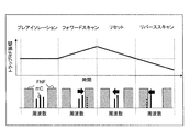
次に、他のアイソレーション方法を説明する。当該方法は、広いアイソレーション窓を有するFNFを印加しながらトラップRF電圧振幅をスキャンする。図7は、この方法を用いるアイソレーションにおける、各ステップでのトラップRF電圧振幅と、アイソレーション窓を模式的に示す。ここでは簡単のため、単一のアイソレーション窓の場合を例として説明する。複数種類のイオンを対象にする場合は、例えば、制御部1は、各種類のイオンのアイソレーション窓を有するFNFを印加し、全てのイオンに対して同時に以下の処理を行えばよい。
まず、プレアイソレーションステップにおいて、制御部21は、前駆体イオンmCの共鳴周波数がアイレーション窓の中心近傍にくるように、アイソレーション幅を広く(5~20Da程度)設定したFNFを印加する。この波形の印加によってイオントラップ7内のイオンの総量を減らし、空間電荷を低減する。次に、フォワードスキャンステップで、制御部21は、FNFを印加しながら、トラップRF電圧振幅を漸増(スキャン)する。
イオンの共鳴周波数はトラップRF電圧振幅に依存するため(数2の数式)、前駆体イオンmCの共鳴周波数がアイソレーション窓の高周波数側端近くになるまでトラップRF電圧振幅をスキャンすることで、前駆体イオンmCより低質量側にあるイオンを排除することができる。
リセットにおいて、制御部21はトラップRF電圧振幅を漸減させる。リバーススキャンでは、制御部21は、さらに、前駆体イオンmCの共鳴周波数がアイソレーション窓の低周波数側端近くになるまでトラップRF電圧振幅を漸減(スキャン)し、前駆体イオンの高質量側にあるイオンを排除する。
FNFを印加しながらトラップRF電圧振幅をスキャンする方法でも、異なるm/zのイオンを同じアイソレーション幅でアイソレートするためには、FNFから取り除く周波数の幅を、アイソレーション対象のイオンのm/zが小さい(q値が高い)場合には広く、アイソレーション対象のイオンのm/zが大きい(q値が低い)場合には狭く、設定する。つまり、アイソレーション窓の幅は、前駆体イオンの質量電荷比が小さいほど広い。
例として、イオンa、b(m/z=ma、mb)をアイソレートする場合について説明する。或るトラップRF電圧振幅において、イオンaをアイソレートするアイソレーション窓の低周波数側端のq値と、イオントラップ7内に保持されるイオンの高質量側の端(ma+Dm)のq値との差を、Δqaとする。また、イオンbをアイソレートするアイソレーション窓の低周波数側端のq値とイオントラップ7内に保持されるイオンの高質量側の端(mb+Dm)のq値との差を、Δqbとする。このとき、以下の関係を満たすようにFNF窓の低周波数側端に対応するq値を定められる。

同様に、あるトラップRF電圧振幅値において、イオンaをアイソレートするアイソレーション窓の高周波数側端とイオントラップ内に保持されるイオンの低質量側端(ma-Dm′)のq値の差を、Dqa′とする。イオンbをアイソレートするアイソレーション窓の高周波数側端とイオントラップ内に保持されるイオンの低質量側端(mb-Dm′)のq値の差をΔqb′とする。ことのとき、以下の関係を満たすようにFNF窓の高周波数側端に対応するq値を定める。

これらq値から、β値とq値との一意の関係及び数1の数式を用いて、周波数に変換してFNFから取り除く周波数を選べば、FNFを印加しながらトラップRF電圧振幅をスキャンしたときに同じアイソレーション幅(Dm+Dm′)でイオンaとイオンbをアイソレートすることができる。
例えば、FNFの各アイソレーション窓の周波数端は、全てのアイソレーション幅が統一原子質量単位で同一となるように、決定されている。例えば、制御部21は、イオンa、bの質量電荷比、Dm、Dm′、βとqとの関係等の情報を保持し、それらから上記方法によりFNFから除く周波数成分の値を算出できる。若しくは、制御部21が保持するFNFの波形情報は、上記方法により決められたアイソレーション窓の周波数位置を示す。
上記例は、FNFにおけるアイソレーション窓の周波数を決定するが、補助電圧の周波数スキャン及びトラップRF電圧の振幅スキャンにおけるアイソレーション窓の決定に対しても、上記方法を適用することができる。以上のように、本実施例は、アイソレーションにおいて、空間電荷の影響による前駆体イオンのロスを低く抑えることができる。
本実施例は、予め定められている異なるm/zの前駆体イオンのイオン量をそれぞれ測定し、測定値が閾値を超える前駆体イオンを選択的に質量分析する。以下において、選択された前駆体イオンをアイソレートするいくつかの異なる方法を説明する。
制御部21は、まず、FNFを使用して特定の前駆体イオンをアイソレートし、それらの質量スペクトル(MS1スペクトル)を測定する。制御部21は、FNFによる前駆体イオンのアイソレーション後、いずれの前駆体イオンの解離を行うことなく、前駆体イオンの質量スキャンを行う。この結果、前駆体イオンのみからなるMS1スペクトルが得られる。
前駆体イオン以外のイオンを排除することで、空間電荷による前駆体イオンのイオントラップからの排出効率の低下、マスシフトを低減することができる。特に前駆体イオンの量が夾雑物イオンの量に比して相対的に少ない場合に有用である。
次に、制御部21は、MS1スペクトルで前駆体イオンの信号強度(イオン量)が閾値を超えている前駆体イオンを測定対象として選択する。制御部21は、選択した前駆体イオンのMSn測定のために、アイソレートする。MSn測定対象の前駆体イオンの組み合わせは、MS1スペクトルの測定結果によって変化する。つまり、MS1測定前において、アイソレートする前駆体イオンのm/zは決まっていない。
一つの方法は、実施例3において説明したように、補助交流電圧の周波数スキャンを使用してアイソレーションを行う。制御部21は、MS1スペクトルにおいて閾値を超える前駆体イオンのm/zに対応する周波数帯をスキップして、補助交流電圧の周波数をスキャンする。制御部21は、RFトラップ電圧の振幅をスキャンしてもよい。これらの方法は、MS1測定の結果に応じて、容易に印加する電圧を制御することができる。
他の方法は、想定している前駆体イオンの全てに対応するアイソレーション窓を有するFNFを予め生成しておき、当該FNFを印加すると同時に、単一周波数の補助交流電圧を印加する。制御部21は、補助交流電圧の周波数を、測定対象の前駆体イオン以外のアイソレーション窓の範囲内でスキャンする。この方法は、実施例3で説明した補助交流電圧の周波数スキャンよりも高速なアイソレーションが可能であり、空間電荷の影響も抑えることができる。
他の方法は、MS1スペクトルで閾値を超えた前駆体イオンの組み合わせをアイソレートするFNFを、MS1スペクトル測定後に高速に生成する。図8は、当該FNFの生成を模式的に示す。
制御部21は、アイソレーション窓を有していないFNFの元波形851を、逆高速フーリエ変換などを使用して予め生成し、メモリに保持する。具体的には、制御部21は、FNF元波形の、各周波数成分の位相、強度の情報852をメモリ内のテーブルに保存する。
制御部21は、MS1測定対象の全ての前駆体イオンの共鳴周波数の値を予め保持している。制御部21は、MS1スペクトルから、MSn測定対象の前駆体イオンを特定し、それらの共鳴周波数を特定する。アイソレーションにおいて、制御部21は、テーブルの情報852を参照して、デジタル波形生成などにより、測定対象の前駆体イオンの共鳴周波数帯(共鳴周波数及びそれらの近傍周波数)の周波数成分853を、FNFの元波形に含まれている周波数成分と逆位相及び同強度で生成する。
制御部21は、時間領域のFNF元波形851とデジタル波形生成した波形853を出力の単位時間ごとに足し合わせて、補助交流電圧854として出力する。この操作により、FNFの元波形の測定対象の前駆体イオンの共鳴周波数周辺の周波数成分が打ち消されるため、測定対象の前駆体イオンの組み合わせをアイソレートすることができる。
なお、本発明は上記した実施例に限定されるものではなく、様々な変形例が含まれる。例えば、上記した実施例は本発明を分かりやすく説明するために詳細に説明したものであり、必ずしも説明したすべての構成を備えるものに限定されるものではない。また、ある実施例の構成の一部を他の実施例の構成に置き換えることが可能であり、また、ある実施例の構成に他の実施例の構成を加えることも可能である。また、各実施例の構成の一部について、他の構成の追加・削除・置換をすることが可能である。
上記の各構成・機能・処理部等は、それらの一部又は全部を、例えば集積回路で設計する等によりハードウェアで実現してもよい。また、上記の各構成、機能等は、プロセッサがそれぞれの機能を実現するプログラムを解釈し、実行することにより、ソフトウェアを使用して実現してもよい。
各機能を実現するプログラム、テーブル、ファイル等の情報は、メモリや、ハードディスク、SSD(Solid State Drive)等の記録装置、または、ICカード、SDカード等の記録媒体に置くことができる。また、制御線や情報線は説明上必要と考えられるものを示しており、製品上必ずしもすべての制御線や情報線を示しているとは限らない。実際には殆どすべての構成が相互に接続されていると考えてもよい。
Claims (10)
- 試料をイオン源においてイオン化する、イオン化ステップと、
前記イオン源で生成されたイオンを、RF電圧を使用してイオントラップにトラップする、トラッピングステップと、
前記イオントラップに前記RF電圧と共に補助交流電圧を印加して、異なる質量電荷比を有する異なる種類の前駆体イオンを前記イオントラップ内に保持しつつ、前記補助交流電圧に共鳴する他のイオンを前記イオントラップから排除して、前記異なる種類の前駆体イオンをアイソレートする、アイソレーションステップと、
前記異なる種類の前駆体イオンの1又は複数種類の前駆体イオンを選択し、前記選択した前駆体イオン以外の非選択前駆体イオンを前記イオントラップ内に保持しつつ、前記選択した前駆体イオンを前記補助交流電圧との共鳴により解離させてフラグメントイオンを生成する、解離ステップと、
前記非選択前駆体イオンを前記イオントラップ内に保持しつつ、前記生成したフラグメントイオンを前記補助交流電圧との共鳴により前記イオントラップから質量選択的に排出して検出器において検出する、質量選択的排出ステップと、を含み、
前記解離ステップと前記質量選択的排出ステップとを繰り返し、前記異なる種類の前駆体イオンの質量測定を行う、質量分析方法。 - 請求項1に記載の質量分析方法であって、
前記解離ステップ及び前記質量選択的排出ステップの少なくとも一方は、前記非選択前駆体イオンが前記補助交流電圧と共鳴しない範囲で、前記補助交流電圧の周波数又は前記RF電圧の振幅をスキャンする、質量分析方法。 - 請求項1に記載の質量分析方法であって、
前記アイソレーションステップにおいて、前記補助交流電圧は、前記異なる種類の前駆体イオンの共鳴周波数のそれぞれを含むノッチを有する、質量分析方法。 - 請求項3に記載の質量分析方法であって、
前記アイソレーションステップは、前記ノッチのノッチ幅が段階的に狭くなるように、前記補助交流電圧を、複数回印加する、質量分析方法。 - 請求項3に記載の質量分析方法であって、
前記アイソレーションステップは、前記RF電圧の振幅を変化させて、前記前駆体イオンと異なるイオンの前記ノッチ内に存在する共鳴周波数を、前記ノッチ外にシフトさせる、質量分析方法。 - 請求項3に記載の質量分析方法であって、
前記アイソレーションステップにおいて、前記ノッチの幅は、前記異なる種類の前駆体イオンの質量電荷比が小さいほど広い、質量分析方法。 - 請求項1に記載の質量分析方法であって、
前記アイソレーションステップは、前記補助交流電圧において、前記異なる種類の前駆体の共鳴周波数を含む複数の第1ノッチ及び前記第1ノッチと異なる第2ノッチを有する電圧を印加しつつ、前記第2ノッチのそれぞれにおいて周波数をスキャンする、質量分析方法。 - 請求項1に記載の質量分析方法であって、
前記アイソレーションステップは、前記異なる種類の前駆体イオンが前記補助交流電圧と共鳴しない範囲で、前記補助交流電圧の周波数又は前記RF電圧の振幅をスキャンする、質量分析方法。 - 請求項1に記載の質量分析方法であって、
前記イオン源の上流側に位置するバルブを制御して、気化した前記試料を間欠的に前記イオン源に導入するステップをさらに有する、質量分析方法。 - 試料をイオン化する、イオン源と、
前記イオン源で生成されたイオンを、RF電圧を使用してトラップする、イオントラップと、
前記イオントラップから質量選択的に排出されたイオンを検出する検出器と、
制御部と、を含み、
前記制御部は、
前記イオントラップに前記RF電圧と共に補助交流電圧を印加して、異なる質量電荷比を有する異なる種類の前駆体イオンを前記イオントラップ内に保持しつつ、前記補助交流電圧に共鳴する他のイオンを前記イオントラップから排除して、前記異なる種類の前駆体イオンをアイソレートする、アイソレーションステップと、
前記異なる種類の前駆体イオンの1又は複数種類の前駆体イオンを選択し、前記選択した前駆体イオン以外の非選択前駆体イオンを前記イオントラップ内に保持しつつ、前記選択した前駆体イオンを前記補助交流電圧との共鳴により解離させてフラグメントイオンを生成する、解離ステップと
前記非選択前駆体イオンを前記イオントラップ内に保持しつつ、前記生成したフラグメントイオンを前記補助交流電圧との共鳴により前記イオントラップから前記検出器に向けて質量選択的に排出する、質量選択的排出ステップと、を実行し、
前記解離ステップと前記質量選択的排出ステップとを繰り返し、前記異なる種類の前駆体イオンの質量測定を行う、質量分析装置。
Applications Claiming Priority (2)
| Application Number | Priority Date | Filing Date | Title |
|---|---|---|---|
| JP2013-134800 | 2013-06-27 | ||
| JP2013134800A JP2015011801A (ja) | 2013-06-27 | 2013-06-27 | 質量分析方法及び質量分析装置 |
Publications (1)
| Publication Number | Publication Date |
|---|---|
| WO2014208336A1 true WO2014208336A1 (ja) | 2014-12-31 |
Family
ID=52141680
Family Applications (1)
| Application Number | Title | Priority Date | Filing Date |
|---|---|---|---|
| PCT/JP2014/065427 Ceased WO2014208336A1 (ja) | 2013-06-27 | 2014-06-11 | 質量分析方法 |
Country Status (2)
| Country | Link |
|---|---|
| JP (1) | JP2015011801A (ja) |
| WO (1) | WO2014208336A1 (ja) |
Cited By (4)
| Publication number | Priority date | Publication date | Assignee | Title |
|---|---|---|---|---|
| US10347477B2 (en) | 2017-03-24 | 2019-07-09 | Thermo Finnigan Llc | Methods and systems for quantitative mass analysis |
| US11004672B2 (en) | 2019-08-27 | 2021-05-11 | Thermo Finnigan Llc | Systems and methods of operation of linear ion traps in dual balanced AC/unbalanced RF mode for 2D mass spectrometry |
| US20210335592A1 (en) * | 2018-10-10 | 2021-10-28 | Purdue Research Foundation | Mass spectrometry via frequency tagging |
| CN115335957A (zh) * | 2020-02-06 | 2022-11-11 | 泰州宸安生物科技有限公司 | 用于单颗粒物分析的质谱仪及方法 |
Families Citing this family (5)
| Publication number | Priority date | Publication date | Assignee | Title |
|---|---|---|---|---|
| JP6730140B2 (ja) * | 2015-11-20 | 2020-07-29 | 株式会社日立ハイテクサイエンス | 発生ガス分析方法及び発生ガス分析装置 |
| JP6280964B2 (ja) * | 2015-11-20 | 2018-02-14 | 株式会社日立ハイテクサイエンス | 発生ガス分析装置及び発生ガス分析方法 |
| EP3373324A1 (en) * | 2017-03-10 | 2018-09-12 | Thermo Finnigan LLC | Methods and systems for quantitative mass analysis |
| CN117012610A (zh) * | 2022-04-28 | 2023-11-07 | 株式会社岛津制作所 | 质谱仪及其真空系统的形成方法 |
| EP4631092A2 (en) * | 2022-12-07 | 2025-10-15 | Teledyne FLIR Defense, Inc. | A mass spectrometer and a method for analyzing a sample therein |
Citations (7)
| Publication number | Priority date | Publication date | Assignee | Title |
|---|---|---|---|---|
| JP2005108578A (ja) * | 2003-09-30 | 2005-04-21 | Hitachi Ltd | 質量分析装置 |
| JP2008309733A (ja) * | 2007-06-18 | 2008-12-25 | Shimadzu Corp | クロマトグラフ質量分析装置用データ処理装置 |
| JP2009150794A (ja) * | 2007-12-21 | 2009-07-09 | Hitachi High-Technologies Corp | 質量分析装置およびその制御方法 |
| JP2011228071A (ja) * | 2010-04-19 | 2011-11-10 | Hitachi High-Technologies Corp | 質量分析装置 |
| JP2012521002A (ja) * | 2009-03-20 | 2012-09-10 | ディーエイチ テクノロジーズ デベロップメント プライベート リミテッド | タンデム質量分析計において複数の前駆体イオンを処理する方法 |
| JP2012533059A (ja) * | 2009-07-07 | 2012-12-20 | ディーエイチ テクノロジーズ デベロップメント プライベート リミテッド | 高いサンプル利用度での質量分光法のための方法および装置 |
| JP2013007637A (ja) * | 2011-06-24 | 2013-01-10 | Hitachi High-Technologies Corp | 質量分析方法 |
-
2013
- 2013-06-27 JP JP2013134800A patent/JP2015011801A/ja active Pending
-
2014
- 2014-06-11 WO PCT/JP2014/065427 patent/WO2014208336A1/ja not_active Ceased
Patent Citations (7)
| Publication number | Priority date | Publication date | Assignee | Title |
|---|---|---|---|---|
| JP2005108578A (ja) * | 2003-09-30 | 2005-04-21 | Hitachi Ltd | 質量分析装置 |
| JP2008309733A (ja) * | 2007-06-18 | 2008-12-25 | Shimadzu Corp | クロマトグラフ質量分析装置用データ処理装置 |
| JP2009150794A (ja) * | 2007-12-21 | 2009-07-09 | Hitachi High-Technologies Corp | 質量分析装置およびその制御方法 |
| JP2012521002A (ja) * | 2009-03-20 | 2012-09-10 | ディーエイチ テクノロジーズ デベロップメント プライベート リミテッド | タンデム質量分析計において複数の前駆体イオンを処理する方法 |
| JP2012533059A (ja) * | 2009-07-07 | 2012-12-20 | ディーエイチ テクノロジーズ デベロップメント プライベート リミテッド | 高いサンプル利用度での質量分光法のための方法および装置 |
| JP2011228071A (ja) * | 2010-04-19 | 2011-11-10 | Hitachi High-Technologies Corp | 質量分析装置 |
| JP2013007637A (ja) * | 2011-06-24 | 2013-01-10 | Hitachi High-Technologies Corp | 質量分析方法 |
Cited By (9)
| Publication number | Priority date | Publication date | Assignee | Title |
|---|---|---|---|---|
| US10347477B2 (en) | 2017-03-24 | 2019-07-09 | Thermo Finnigan Llc | Methods and systems for quantitative mass analysis |
| US20210335592A1 (en) * | 2018-10-10 | 2021-10-28 | Purdue Research Foundation | Mass spectrometry via frequency tagging |
| US11984311B2 (en) * | 2018-10-10 | 2024-05-14 | Purdue Research Foundation | Mass spectrometry via frequency tagging |
| US11004672B2 (en) | 2019-08-27 | 2021-05-11 | Thermo Finnigan Llc | Systems and methods of operation of linear ion traps in dual balanced AC/unbalanced RF mode for 2D mass spectrometry |
| US11651948B2 (en) | 2019-08-27 | 2023-05-16 | Thermo Finnigan Llc | Systems and methods of operation of linear ion traps in dual balanced AC/unbalanced RF mode for 2D mass spectrometry |
| US12040174B2 (en) | 2019-08-27 | 2024-07-16 | Thermo Finnigan Llc | Systems and methods of operation of linear ion traps in dual balanced AC/unbalanced RF mode for 2D mass spectrometry |
| CN115335957A (zh) * | 2020-02-06 | 2022-11-11 | 泰州宸安生物科技有限公司 | 用于单颗粒物分析的质谱仪及方法 |
| US20230014104A1 (en) * | 2020-02-06 | 2023-01-19 | Shanghai Polaris Biology Co., Ltd. | Devices and methods for generating resonance excitation for an ion manipulation apparatus |
| EP4100731A4 (en) * | 2020-02-06 | 2023-11-08 | Shanghai Polaris Biology Co., Ltd. | DEVICES AND METHODS FOR PRODUCING RESONANCE EXCITATION FOR ION HANDLING APPARATUS |
Also Published As
| Publication number | Publication date |
|---|---|
| JP2015011801A (ja) | 2015-01-19 |
Similar Documents
| Publication | Publication Date | Title |
|---|---|---|
| WO2014208336A1 (ja) | 質量分析方法 | |
| JP6748755B2 (ja) | 小型質量分析器を用いたサンプル定量化 | |
| US20230343575A1 (en) | Ion separator | |
| JP5324457B2 (ja) | 静電型イオントラップ | |
| JP5603246B2 (ja) | 質量分析装置 | |
| EP2498272B1 (en) | Mass spectrometric method and mass spectrometer | |
| JP6948500B2 (ja) | 質量分析によりガスを検査するための方法および質量分析計 | |
| CN110506320B (zh) | 具有增加的占空比的质谱分析 | |
| EP2789007B1 (en) | Systems, devices, and methods for sample analysis using mass spectrometry | |
| JP5303273B2 (ja) | フーリエ変換イオンサイクロトロン共鳴質量分析法についての方法及び装置 | |
| WO2011007528A1 (ja) | 質量分析計及び質量分析方法 | |
| JP6409987B2 (ja) | イオントラップ質量分析装置及び該装置を用いた質量分析方法 | |
| US20130001415A1 (en) | Frequency scan linear ion trap mass spectrometry | |
| JP2012533059A (ja) | 高いサンプル利用度での質量分光法のための方法および装置 | |
| WO2015150806A1 (en) | Method of optimising spectral data | |
| JP5600430B2 (ja) | 質量分析装置及び質量分析方法 | |
| US12500074B2 (en) | Characterizing quadrupole transmitting window in mass spectrometers | |
| Nibbering | Principles and applications of Fourier transform ion cyclotron resonance mass spectrometry. Plenary lecture | |
| JP5737144B2 (ja) | イオントラップ質量分析装置 | |
| US20240038524A1 (en) | Mass spectrometer and mass spectrometry method | |
| CN113496866A (zh) | 逆流均匀场离子迁移率谱仪 | |
| US20230126290A1 (en) | Ion activation and fragmentation in sub-ambient pressure for ion mobility and mass spectrometry | |
| JP5206605B2 (ja) | イオントラップ質量分析装置 | |
| Yan-Qiu et al. | Analytical performance of printed circuit board ion trap array mass analyzer with electrospray ionization | |
| WO2022270469A1 (ja) | 質量分析装置、質量分析システム及び質量分析方法 |
Legal Events
| Date | Code | Title | Description |
|---|---|---|---|
| 121 | Ep: the epo has been informed by wipo that ep was designated in this application |
Ref document number: 14817861 Country of ref document: EP Kind code of ref document: A1 |
|
| NENP | Non-entry into the national phase |
Ref country code: DE |
|
| 122 | Ep: pct application non-entry in european phase |
Ref document number: 14817861 Country of ref document: EP Kind code of ref document: A1 |