WO2014203764A1 - オイル劣化センサ及びオイル劣化検出方法 - Google Patents
オイル劣化センサ及びオイル劣化検出方法 Download PDFInfo
- Publication number
- WO2014203764A1 WO2014203764A1 PCT/JP2014/065293 JP2014065293W WO2014203764A1 WO 2014203764 A1 WO2014203764 A1 WO 2014203764A1 JP 2014065293 W JP2014065293 W JP 2014065293W WO 2014203764 A1 WO2014203764 A1 WO 2014203764A1
- Authority
- WO
- WIPO (PCT)
- Prior art keywords
- oil
- ionic liquid
- liquid film
- electrode
- sensitive
- Prior art date
- Legal status (The legal status is an assumption and is not a legal conclusion. Google has not performed a legal analysis and makes no representation as to the accuracy of the status listed.)
- Ceased
Links
Images


Classifications
-
- G—PHYSICS
- G01—MEASURING; TESTING
- G01N—INVESTIGATING OR ANALYSING MATERIALS BY DETERMINING THEIR CHEMICAL OR PHYSICAL PROPERTIES
- G01N27/00—Investigating or analysing materials by the use of electric, electrochemical, or magnetic means
- G01N27/26—Investigating or analysing materials by the use of electric, electrochemical, or magnetic means by investigating electrochemical variables; by using electrolysis or electrophoresis
- G01N27/403—Cells and electrode assemblies
- G01N27/414—Ion-sensitive or chemical field-effect transistors, i.e. ISFETS or CHEMFETS
-
- G—PHYSICS
- G01—MEASURING; TESTING
- G01N—INVESTIGATING OR ANALYSING MATERIALS BY DETERMINING THEIR CHEMICAL OR PHYSICAL PROPERTIES
- G01N27/00—Investigating or analysing materials by the use of electric, electrochemical, or magnetic means
- G01N27/26—Investigating or analysing materials by the use of electric, electrochemical, or magnetic means by investigating electrochemical variables; by using electrolysis or electrophoresis
- G01N27/28—Electrolytic cell components
- G01N27/30—Electrodes, e.g. test electrodes; Half-cells
- G01N27/36—Glass electrodes
-
- G—PHYSICS
- G01—MEASURING; TESTING
- G01N—INVESTIGATING OR ANALYSING MATERIALS BY DETERMINING THEIR CHEMICAL OR PHYSICAL PROPERTIES
- G01N33/00—Investigating or analysing materials by specific methods not covered by groups G01N1/00 - G01N31/00
- G01N33/26—Oils; Viscous liquids; Paints; Inks
- G01N33/28—Oils, i.e. hydrocarbon liquids
- G01N33/2835—Specific substances contained in the oils or fuels
- G01N33/2876—Total acid number
Definitions
- the present invention relates to an oil deterioration sensor and an oil deterioration detection method, and specifically detects the deterioration of various oils used in the industry (for example, engine oil, turbine oil, hydraulic fluid, various lubricating oils, etc.). And a sensor for the same.
- oils used in the industry for example, engine oil, turbine oil, hydraulic fluid, various lubricating oils, etc.
- the total acid value is the amount of potassium hydroxide required to neutralize the total amount of acidic components contained in 1 g of sample oil, that is, the total amount of acidic substances in additives and organic acids generated during use.
- the total acid number generally increases as the oil degrades.
- a pH electrode sensor including a glass electrode as a pH electrode and a reference electrode is known as an apparatus for measuring the pH of an aqueous solution (see Patent Document 1).
- a pH electrode sensor is used by being immersed in a sample solution.
- the surface of the glass film generates a potential difference corresponding to the pH of the sample solution.
- the pH of the sample solution can be obtained by measuring this potential difference using a reference electrode capable of presenting a constant reference potential.
- Patent Document 2 two electrode plates installed in parallel to each other in the oil flow path, and an ammeter that measures the current that flows when an AC voltage is applied between the two electrode plates
- a method for determining the deterioration of the oil based on the conductivity and the dielectric constant has been proposed.
- the pH of the aqueous solution can be directly and continuously measured with the pH electrode sensor immersed in the aqueous solution.
- the sample is non-polar oil, even if the pH electrode sensor is immersed directly in the oil, the affinity between the glass electrode of the pH electrode and the oil is poor. It cannot be applied to deterioration detection.
- At least some embodiments of the present invention directly reduce the deterioration of the oil itself even when the measurement object is oil that has not been subjected to operations such as dissolution and dilution.
- An object of the present invention is to provide an oil deterioration sensor that can be detected.
- at least some embodiments of the present invention aim to provide an oil deterioration detection method using such an oil deterioration sensor.
- An oil deterioration sensor is an oil deterioration sensor that detects a deterioration of the oil by detecting a polar substance generated by the deterioration of the oil, An ionic liquid film containing an ionic liquid and capable of at least partially contacting the oil when detecting deterioration of the oil; A sensitive electrode having a sensitive portion that is at least partially covered by the ionic liquid film and configured to be sensitive to movement of the polar substance from the oil to the ionic liquid film; A reference electrode in electrical communication with the ionic liquid film; A potentiometer for measuring a potential difference between the sensitive electrode and the reference electrode;
- the inventor has developed a sensitive electrode having a sensitive portion at least partially covered with an ionic liquid film in a state where the ionic liquid film is immersed in a nonpolar liquid, and an ionic liquid film electrically It has been found that a potential difference corresponding to the amount of the polar substance existing in the ionic liquid film occurs between the communicating reference electrodes. This is because the polar ionic liquid film is interposed between the nonpolar liquid and the sensitive part of the sensitive electrode, so that the sensitive part can be sensitive to the movement of the polar substance from the nonpolar liquid to the ionic liquid film. It is thought that it was because of it.
- the potential difference generated between the sensitive electrode and the reference electrode is the polarity in the nonpolar liquid. It is an indicator of the amount of a substance. Therefore, the polar substance in the nonpolar liquid can be detected from the potential difference generated between the sensitive electrode and the comparison electrode.
- the oil deterioration sensor is based on the knowledge of the present inventor. That is, since the ionic liquid film can contact the oil to be measured, when the oil deterioration sensor is immersed in the oil, polar substances generated in the oil due to the deterioration of the oil are between the oil and the ionic liquid film.
- the ionic liquid film covers at least a part of the sensitive part of the sensitive electrode, and the reference electrode is in electrical communication with the ionic liquid film. Therefore, an ion is interposed between the sensitive electrode and the comparative electrode. A potential difference corresponding to the amount of polar substance present in the liquid film is generated. By measuring this potential difference with a potentiometer, the degree of deterioration of the oil can be detected from the potential difference. Further, as described above, the measurement principle of the oil deterioration sensor can be established even when the liquid to be measured is non-polar. Therefore, the oil deterioration sensor uses oil that has not been subjected to operations such as dissolution and dilution. Even if it is used as it is as a measurement object, it can be used.
- the sensitive part may be configured to be sensitive to a change in the hydrogen ion concentration in the ionic liquid film accompanying movement of the polar substance from the oil to the ionic liquid film.
- the sensitive part of the sensitive electrode is sensitive to changes in the hydrogen ion concentration, and a potential difference corresponding to the concentration of an acidic substance such as an organic acid generated as the oil deteriorates. And between the reference electrode and the reference electrode. Therefore, the deterioration of the oil can be detected by measuring this potential difference with a potentiometer.
- the sensitive electrode may be a glass electrode or an ion sensitive field effect transistor (ISFET) electrode.
- ISFET ion sensitive field effect transistor
- the reference electrode includes a reference electrode part in which the potential difference is formed with the sensitive electrode, an internal liquid in which at least a part of the reference electrode part is immersed, and the internal liquid You may have the liquid junction provided between the said ionic liquid films
- the ionic liquid film may be arranged so as to at least partially cover both the sensitive part and the liquid junction part. By directly covering both the sensitive part and the liquid junction part with the ionic liquid film, a direct electrical communication between the sensitive electrode and the reference electrode can be formed by the ionic liquid film.
- the oil deterioration sensor further includes a protection part that is provided between the ionic liquid film and the oil and partially covers the ionic liquid film
- the ionic liquid film may be configured such that at least a part of a region that is not covered by the protective portion is in contact with the oil. If the sample oil in which the oil deterioration sensor is immersed is in a stirring state, all or part of the ionic liquid film covering the sensitive electrode or the like may be washed away. Therefore, as in the above-described embodiment, a protective part that partially covers the ionic liquid film is provided, and at least a part of the ionic liquid film is not covered with the protective part, so that the polar substance in the oil is brought into contact with the oil. The movement of the ionic liquid film to the oil can be reduced while ensuring the movement of the ionic liquid film to the ionic liquid film.
- the sensitive part and the liquid junction part are disposed on both sides of the ionic liquid film so as to sandwich the ionic liquid film, A part of the ionic liquid film may be in contact with the oil without being covered with the sensitive part and the liquid junction part.
- both sides of the ionic liquid film are not in contact with the oil, so that the outflow of the ionic liquid film to the oil can be reduced. it can.
- membrane can contact oil, the movement to the ionic liquid film
- the ionic liquid film may have a kinematic viscosity at 40 ° C. of 12 mm 2 / s or more. By increasing the viscosity of the ionic liquid film, the outflow of the ionic liquid film to the oil can be reduced.
- the ionic liquid film may include a thickener.
- the viscosity of the ionic liquid film can be increased, and thereby the outflow of the ionic liquid film to the oil can be reduced.
- An oil deterioration detection method includes an ionic liquid film containing an ionic liquid, a sensitive electrode having a sensitive part covered at least in part by the ionic liquid film, and an electric current applied to the ionic liquid film.
- An oil deterioration detection method comprising detecting an oil deterioration by detecting a polar substance generated by oil deterioration using an oil deterioration sensor comprising a reference electrode that is communicated with the oil, An immersing step of immersing the oil degradation sensor in the oil such that the ionic liquid film is at least partially in contact with the oil and sensitive to movement of the polar substance from the oil to the ionic liquid film; In a state where the oil deterioration sensor is immersed in the oil, a measurement step of measuring a potential difference between the sensitive electrode and the comparison electrode; A deterioration detecting step of detecting deterioration of the oil based on the potential difference.
- the oil deterioration detection method since at least a part of the sensitive electrode of the oil deterioration sensor is covered with the ionic liquid film, when the oil deterioration sensor is immersed in the oil to be measured, it is caused by the oil deterioration.
- the polar substance generated in the oil can move to the ionic liquid film. Therefore, even when the oil itself that has not been subjected to operations such as dissolution and dilution is to be measured, the potential difference generated between the sensitive electrode and the reference electrode as the polar substance moves from the oil to the ionic liquid membrane Is measured with a potentiometer, it is possible to detect the deterioration of the oil itself from the potential difference.
- the ionic liquid film can contact the oil to be measured, and the polar substance generated in the oil can move into the ionic liquid film. Without adding oil, the measurement object can be used as it is. Moreover, since the sensitive part of the sensitive electrode is configured to be sensitive to the movement of the polar substance generated by the deterioration of the oil, the deterioration of the oil itself can be detected.
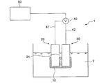
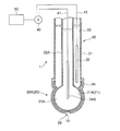
- FIG. 1 is a diagram showing an outline of the entire configuration of an oil deterioration sensor according to an embodiment.
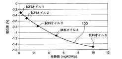
- FIG. 2 is a graph showing the relationship between the potential difference between the sensitive electrode and the reference electrode of the oil deterioration sensor and the total acid value of the oil.
- the oil deterioration sensor 1 includes a sensitive electrode 20 having a sensitive portion 21, a comparative electrode 30, and a potentiometer 40 capable of detecting a potential difference between the sensitive electrode 20 and the comparative electrode 30.
- the measurement principle of the oil deterioration sensor 1 is that the ionic liquid film is electrically communicated with a sensitive electrode having a sensitive part covered at least in part by the ionic liquid film in a state where the ionic liquid film is immersed in a nonpolar liquid. This is based on the knowledge of the present inventor that a potential difference corresponding to the amount of the polar substance existing in the ionic liquid film is generated between the reference electrode and the reference electrode.
- the oil deterioration sensor 1 according to the embodiment includes an ionic liquid film 10 that can at least partially contact the oil 2 when the deterioration of the oil 2 is detected. And the ionic liquid film
- membrane 10 is provided so that at least one part of the sensitive part 21 of the sensitive electrode 20 may be covered.
- the reference electrode 30 is in electrical communication with the ionic liquid film 10.
- the oil deterioration sensor 1 having the above configuration, since the ionic liquid film 10 can contact the oil 2 to be measured, when the oil deterioration sensor 1 is immersed in the oil 2, the oil 2 is deteriorated due to the deterioration of the oil 2.
- the polar substance generated in the step moves into the ionic liquid film 10 via the interface between the oil 2 and the ionic liquid film 10. Since the ionic liquid film 10 covers at least a part of the sensitive portion 21 of the sensitive electrode 20 and the comparative electrode 30 is electrically connected to the ionic liquid film 10, the sensitive electrode 20 and the comparative electrode 30. A potential difference corresponding to the amount of the polar substance existing in the ionic liquid film 10 is generated between the two.
- the degree of deterioration of the oil 2 can be detected from the potential difference.
- the above-described measurement principle of the oil deterioration sensor 1 can be established even if the liquid to be measured is non-polar. Therefore, the oil deterioration sensor 1 uses the oil 2 that has not been subjected to operations such as dissolution and dilution as it is. Even if it can be used.
- the sensitive portion 21 of the sensitive electrode 20 is configured to be sensitive to movement of polar substances generated in the oil 2 due to deterioration of the oil 2 to the ionic liquid film 10.
- polar substances generated in the oil 2 due to deterioration of the oil 2 to the ionic liquid film 10.
- organic acids such as carboxylic acid, and a sulfuric acid can be mentioned, for example.
- the specific configuration of the sensitive electrode 20 will be described in detail later with reference to FIGS.
- the comparison electrode 30 is electrically connected to the ionic liquid film 10 that covers the sensitive portion 21 of the sensitive electrode 20.
- the comparison electrode 30 is in electrical communication with the ionic liquid film 10 by directly contacting the ionic liquid film 10 covering the sensitive portion 21 of the sensitive electrode 20, as shown in FIG. .
- the reference electrode 30 is formed by using an electrode solution of the sensitive electrode 20 via an electrolyte solution such as an aqueous solution of potassium chloride or an aqueous solution of sodium chloride, or a solid made of a conductor such as an electrically conductive metal or an electrically conductive resin.
- the ionic liquid film 10 covering the sensitive part 21 is electrically communicated.
- the specific configuration of the comparison electrode 30 will be described in detail later with reference to FIGS.
- the potentiometer 40 is not particularly limited as long as the potential difference between the sensitive electrode 20 and the comparison electrode 30 can be measured.
- one potentiometer 40 is connected to the sensitive electrode 20 via a conductive wire 41.
- a voltmeter in which the terminal is connected and the other terminal is connected to the comparison electrode 30 through the conducting wire 42 can be used.
- the oil deterioration sensor 1 includes a deterioration determination unit 50 for determining the degree of deterioration of the oil 2 to be measured based on the potential difference obtained by the potentiometer 40.
- the deterioration determination unit 50 includes a storage unit in which a correlation between the potential difference between the sensitive electrode 20 and the comparison electrode 30 and the degree of oil deterioration is stored, and by applying a measurement value by the potentiometer 40 to the correlation.
- the deterioration degree of the oil 2 may be determined.
- the correlation stored in the storage unit may be acquired in advance using sample oil whose degradation degree is known.
- the relationship between the potential difference between the sensitive electrode 20 and the comparison electrode 30 and the total acid value of the oil is acquired in advance using sample oil and stored in the storage unit of the deterioration determination unit 50.
- the deterioration determination unit 50 can determine the degree of deterioration of the oil 2 by applying the measured value of the potentiometer 40 to the relationship and estimating the total acid value of the oil 2.
- the deterioration determination unit 50 may have an output unit (not shown) for outputting the determination result of the deterioration degree of the oil 2.
- the ionic liquid contained in the ionic liquid film 10 is a salt that exists as a liquid in an environment where oil deterioration is detected.
- the ionic liquid of the ionic liquid film 10 is an ionic liquid that exists as a liquid within a temperature range of t 0 ⁇ 20 ⁇ t ⁇ t 0 +100, where t 0 [° C.] is a temperature at which oil deterioration is detected. It may be.
- the ionic liquid of the ionic liquid film 10 may be insoluble in oil.
- the ionic liquid has a property of not substantially dissolving in the oil 2 to be measured.
- the salt of an ionic liquid can be comprised by the combination of various cations and anions.
- the cation constituting the salt of the ionic liquid include imidazolium ions, pyridinium ions, pyrazolium ions, piperidinium ions, pyrrolidinium ions, morpholine ions, pyrrole ions, phosphonium ions, and quaternary ammonium ions.
- Examples thereof include at least one selected from the group consisting of ions, sulfonium-based ions, isoxazolium-based ions, and the like.
- the anion constituting the salt of the ionic liquid includes, for example, a phosphinate ion, an imide ion, a carboxylate ion, a phosphate ion, a borate ion, a thiocyanate ion, and a thiosalicylate ion. There may be mentioned at least one selected from the group.
- ionic liquid salts include, for example: Trihexyl-tetradecyl-phosphonium / bis (2,4,4-trimethyl-pentyl) phosphinate, 1-ethyl-3-methyl-imidazolium / bis (pentafluoroethylsulfonyl) imide, 1-butyl-1-methyl-pyrrolidinium / bis (trifluoromethylsulfonyl) imide, Tetrabutyl-ammonium / bis (trifluoromethylsulfonyl) imide, Trihexyl-tetradecyl-phosphonium / decanoate, 1-butyl-3- (3,3,4,4,5,5,6,6,7,7,8,8,8-tridecafluorooctyl) -imidazolium / hexafluorophosphate, 1-methyl-3- (3,3,4,4,5,5,6,6,7,7,8,8,8
- the kinematic viscosity at 40 ° C. of the ionic liquid film 10 is 12 mm 2 / s or more. In this case, even when the oil 2 in a stirring state is a measurement target, the ionic liquid film 10 covering at least a part of the sensitive electrode 20 is easily held on the electrode surface.
- the ionic liquid film 10 may contain a thickener.
- the ionic liquid film 10 When the ionic liquid film 10 contains a thickener, the ionic liquid film 10 enters a grease state or a state equivalent thereto, and the viscosity of the ionic liquid film 10 increases. Therefore, even when the oil 2 in a stirring state is a measurement target, the ionic liquid film 10 can be easily held on the electrode surface.
- the thickener for example, soaps such as calcium soap and lithium soap, urea thickener, polytetrafluoroethylene (PTFE), organic thickener represented by melamine cyanurate (MCA), Alternatively, metals such as copper and silver, metal oxides such as zinc oxide and titanium oxide, nitrides such as boron nitride, and inorganic fine powders such as carbon black can be used.
- the mass may be 3% by mass or 3 to 30% by mass.
- the ionic liquid film 10 may contain fine powder composed of an inorganic substance or an organic substance in place of or in addition to the thickener.
- the ionic liquid film 10 contains an inorganic or organic fine powder, the ionic liquid film 10 becomes semi-solid and the viscosity of the ionic liquid film 10 increases. Therefore, even when the oil 2 in a stirring state is a measurement target, the ionic liquid film 10 can be easily held on the electrode surface.
- fine powders made of inorganic or organic materials include metal oxides such as zinc oxide and titanium oxide, ceramics such as alumina and silicon nitride, nitrides such as boron nitride, and fluorine resins such as PTFE.
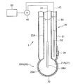
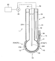
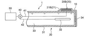
- FIGS. 3 to 5 are schematic sectional views showing an oil deterioration sensor using a glass electrode according to the embodiment.
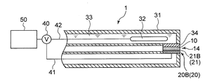
- 6 to 9 are schematic cross-sectional views showing an oil deterioration sensor using an ISFET electrode.
- FIG. 10 is a diagram illustrating a schematic configuration of an ISFET electrode in some embodiments.
- the sensitive portion 21 of the sensitive electrode 20 is configured to be sensitive to changes in the hydrogen ion concentration in the ionic liquid film 10 as the polar substance moves from the oil 2 to the ionic liquid film 10. Is done.
- Examples of the sensitive portion 21 having such a configuration include the glass thin film 21A of the glass electrode 20A shown in FIGS. 3 to 5 and the ion sensitive film 21B of the ISFET electrode 20B shown in FIGS. .
- the sensitive electrode 20 is a glass electrode 20 ⁇ / b> A having a glass thin film 21 ⁇ / b> A as the sensitive portion 21.
- the glass thin film 21 ⁇ / b> A as the sensitive portion 21 is sensitive to a change in the hydrogen ion concentration in the ionic liquid film 10 due to the movement of the polar substance from the oil 2 to the ionic liquid film 10, and is compared with the sensitive electrode 20.
- a potential difference corresponding to the hydrogen ion concentration is formed between the electrode 30 and the electrode 30.
- the glass electrode 20A as the sensitive electrode 20 is provided with an insulating glass electrode support tube 22A and a tip of the glass electrode support tube 22A.
- the internal electrode 23 for example, a silver / silver chloride electrode is used.
- a buffer solution containing potassium chloride having a constant pH of about 7 can be used. In the exemplary embodiment shown in FIGS.
- the comparison electrode 30 is provided on the outer peripheral side of the glass electrode 20 ⁇ / b> A as the sensitive electrode 20.
- an annular comparison electrode support tube 31 of the comparison electrode 30 is provided so as to surround the glass electrode support tube 22A of the glass electrode 20A.
- the comparison electrode 30 may be provided on the inner peripheral side of the glass electrode 20 ⁇ / b> A as the sensitive electrode 20.
- an annular glass electrode support tube 22A of the glass electrode 20A may be provided so as to surround the comparison electrode support tube 31 of the comparison electrode 30.
- the sensitive electrode 20 is an ion sensitive field effect transistor (ISFET) electrode 20B having an ion sensitive membrane (ISM) 21B (see FIG. 10) as the sensitive portion 21. is there.
- ISFET ion sensitive field effect transistor
- the ion sensitive film 21B as the sensitive part 21 is sensitive to a change in the hydrogen ion concentration in the ionic liquid film 10 accompanying the movement of the polar substance from the oil 2 to the ionic liquid film 10, and a drain current which will be described later. Id is affected.
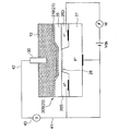
- the ISFET electrode 20B as the sensitive electrode 20 includes an ion sensitive portion 21 as a sensitive portion 21 provided on the semiconductor substrate 60 via the semiconductor substrate 60 and the insulating layer 25, as shown in FIG.
- the semiconductor substrate 60 includes a P-type semiconductor portion 27 and a pair of N-type semiconductor portions 26 (26S, 26D) provided on the P-type semiconductor portion 27.
- the pair of N-type semiconductor portions 26 (26S, 26D) correspond to the source 26S and the drain 26D of the ion-sensitive field effect transistor, respectively.
- the source 26S and the drain 26D are disposed with a channel region 28 therebetween.
- the ion sensitive film 21B is insulated from the semiconductor substrate 60 by the insulating layer 25B.
- the potentiometer 40 is connected to the source 26S of the ISFET electrode 20B via the lead 41 and compared via the lead 42. Connected to the electrode 30.
- the ISFET electrode 20 ⁇ / b> B as the sensitive electrode 20 is disposed on the outer peripheral surface of the comparison electrode support tube 31 of the comparison electrode 30.
- the ISFET electrode 20B as the sensitive electrode 20 is fitted into the hole provided in the comparison electrode support tube 31.
- the measurement principle of the oil deterioration sensor 1 provided with the ISFET electrode 20B in one embodiment is as follows.
- the current (drain current I d ) flowing between the source 26S and the drain 26D via the channel region 28 is not only the voltage V ds between the source 26S and the drain 26D, but also the ion sensitive contact with the ionic liquid film 10. It also depends on the surface potential of the membrane 21B. This is because the execution gate voltage actually applied to the semiconductor substrate 60 changes as a result of the surface potential of the ion sensitive film 21B changing according to the hydrogen ion concentration in the ionic liquid film 10.
- the potential difference between the source 26S and the comparison electrode 30 measured by the potentiometer 40 in a state where the drain current Id and the source-drain voltage Vds are maintained constant is the hydrogen ion concentration in the ionic liquid film 10. It can be used as an index indicating In this way, the potential difference between the sensitive electrode 20 (ISFET electrode 20B) and the comparison electrode 30 (specifically, the source 26S and the comparison electrode 30) measured by the potentiometer 40 by the oil deterioration sensor 1 provided with the ISFET electrode 20B. The deterioration of the oil 2 can be detected based on the potential difference between the two.
- the ion sensitive film 21B only needs to be sensitive to hydrogen ions, and for example, Si 3 N 4 , Al 2 O 3 or Ta 2 O 5 can be used as the material.
- the comparison electrode 30 includes a comparison electrode support tube 31, a reference electrode portion 32 provided inside the comparison electrode support tube 31, and a reference electrode portion 32.
- the internal liquid 33 with which it fills in the comparison electrode support tube 31, and the liquid junction part 34 provided between the internal liquid 33 and the sample of a measuring object.
- the liquid junction 34 is a portion where the internal liquid 33 and the ionic liquid film 10 are in electrical contact.
- the liquid junction 34 only needs to have a fine hole so that the comparison electrode 30 and the ionic liquid film 10 are in electrical communication.
- a porous material such as alumina or zirconia is used as the material. it can.
- the reference electrode unit 31 may be any electrode that exhibits a constant potential regardless of the hydrogen ion concentration of the sample to be measured.
- a silver / silver chloride electrode is used.
- the internal liquid 32 for example, a potassium chloride solution is used.
- the ionic liquid film 10 includes the sensitive portion 21 (21A, 21B) of the sensitive electrode 20 (20A, 20B) and the liquid junction portion 34 of the comparative electrode 30. And at least partially covering both.
- the ionic liquid film 10 is disposed so as to at least partially cover only the sensitive portion 21 (21A, 21B) of the sensitive electrode 20 (20A, 20B).
- the liquid junction part 34 of the comparison electrode 30 is a solid composed of an electrolyte solution such as a potassium chloride aqueous solution or a sodium chloride aqueous solution, or a conductor such as a conductive metal or a conductive resin. Is electrically connected to the ionic liquid film 10 via the.
- the oil deterioration sensor 1 further includes a protection unit 11 that partially covers the ionic liquid film 10.
- the protection unit 11 is provided between the ionic liquid film 10 and the oil 2. At least a part of the region of the ionic liquid film 10 that is not covered by the protection unit 11 is in contact with the oil 2.
- the protection part 11 that covers the ionic liquid film 10 the outflow of the ionic liquid film 10 that covers the sensitive part 21 (21A, 21B) of the sensitive electrode 20 (20A, 20B) to the oil 2 can be reduced.
- the shape of the protection part 11 is not particularly limited, and can be maintained such that the ionic liquid 10 covers the sensitive electrode 20 by being arranged outside the sensitive electrode 20 covered by the ionic liquid 10 such as a plate shape. Any shape is acceptable.
- the material of the protection part 11 should just be a thing which does not melt
- the glass electrode 20A and the glass electrode support are interposed between the ionic liquid 10 and the oil 2 covering the comparison electrode 30 formed around the spherical glass electrode 20A and the glass electrode support tube 22A.
- a protection part 11 having a shape surrounding a part of the tube 22A is provided.
- a plate-like protection unit 11 is provided between the plate-like ionic liquid 10 and the oil 2.
- a region where the ionic liquid film 10 is not covered with the protective part 11 is formed by at least one opening 13 provided in the protective part 11.
- the end portion 12 of the ionic liquid film 10 is not covered by the protective portion 11, thereby forming a region where the ionic liquid film 10 is not covered by the protective portion 11. .
- the sensitive part 21 (21A, 21B) and the liquid junction part 34 are arranged on both sides of the ionic liquid film 10 so as to sandwich the ionic liquid film. .
- a part of the ionic liquid film 10 can contact the oil 2 without being covered by the sensitive part 21 (21A, 21B) and the liquid junction part 34. Since the ionic liquid film 10 is sandwiched between the sensitive part 21 (21A, 21B) and the liquid junction part 34, both side surfaces of the ionic liquid film 10 are not in contact with the oil 2, so that the oil 2 of the ionic liquid film 10 Can be reduced. Moreover, since a part of the ionic liquid film 10 is not covered with the sensitive part 21 (21A, 21B) and the liquid junction part 34 and can contact the oil 2, the contact between the ionic liquid film 10 and the oil 2 is prevented. Secured.
- the ionic liquid film 10 is formed between the glass thin film 21A of the glass electrode 20A and the liquid junction part 34 of the comparison electrode 30 provided so as to surround the glass thin film 21A.
- the portion 29 covering the bottom of the glass electrode 20 ⁇ / b> A is not covered with the glass thin film 21 ⁇ / b> A and the liquid junction 34, and can contact the oil 2.
- the ion sensitive film 21B of the ISFET electrode 20B and the liquid junction 34 of the comparison electrode 30 are opposed to each other, and the ionic liquid film 10 is formed in the space between them. Further, the end surface 14 of the ionic liquid film 10 is not covered with the ion sensitive film 21 ⁇ / b> B and the liquid junction 34, and can contact the oil 2.
- an oil deterioration detection method That is, a method for measuring the potential difference between the sensitive electrode 20 and the comparison electrode 30 with the potentiometer 40 using the oil deterioration sensor 1 and detecting the deterioration of the oil 2 based on the measurement result of the potentiometer 40 will be described. .
- the relationship between the potential difference between the sensitive electrode and the reference electrode and the total acid value of the oil using the sample oil whose content of the acidic component is known (see FIG. 2) Ask for.
- the potential difference between the sensitive electrode 20 and the reference electrode 30 of the oil deterioration sensor 1 is measured by the potentiometer 40 for each of the five types of sample oils (sample oil 1 to sample oil 5 shown in FIG. 2) having different total acid values.
- the oil deterioration sensor 1 is immersed in each sample oil so that the ionic liquid film 10 comes into contact with each sample oil and is sensitive to the movement of polar substances from each sample oil to the ionic liquid film 10.
- the potential difference between the sensitive electrode 20 and the reference electrode 30 is measured. Then, the total acid value (unit: mg KOH / g) is plotted on the horizontal axis, and the measurement result of the potential difference (unit: V) measured at each total acid value is plotted on the vertical axis. For example, comparison with a sensitive electrode as shown in FIG. A relationship between the potential difference from the electrode and the total acid value of the oil (calibration curve 100) is obtained. The relationship (calibration curve 100) between the potential difference between the sensitive electrode and the reference electrode and the total acid value of the oil is stored in the storage unit of the deterioration determination unit 50 of the oil deterioration sensor 1.
- the oil deterioration sensor 1 is immersed in the measurement target oil so that the ionic liquid film 10 contacts the measurement target oil and is sensitive to the movement of the polar substance from the measurement target oil to the ionic liquid film 10. To do. Then, the potential difference between the sensitive electrode 20 and the comparative electrode 30 is measured in a state where the oil deterioration sensor 1 is immersed in the oil to be measured. The deterioration determination unit 50 obtains the total acid value corresponding to the measured potential difference from the relationship between the potential difference between the sensitive electrode and the reference electrode stored in advance and the total acid value of the oil, and the measurement target is obtained based on the total acid value. Determine the deterioration of oil.
- the oil deterioration sensor 1 according to the above-described embodiment was produced, and a test for detecting oil deterioration was performed.
- a pH electrode comprising a glass electrode having a glass thin film and a reference electrode having a liquid junction and configured to exhibit a pH corresponding to a potential difference between the glass electrode and the liquid junction was prepared.
- the oil deterioration sensor shown in FIG. 3 was obtained by forming an ionic liquid film so as to cover the glass thin film of the glass electrode and the liquid junction of the comparative electrode.
- the ionic liquid film was formed using an ionic liquid containing 98% content of an ionic liquid having 1-methyl-3-octyl-imidazolium ions as cations and chlorine ions as anions.
- the oil deterioration sensor obtained as described above was immersed in undegraded engine oil having a total base number of 6.8 mgKOH / g and a total acid number of 1.8 mgKOH / g. At this time, the ionic liquid film of the oil deterioration sensor was brought into contact with the engine oil. Before the start of immersion, the pH indication value of the oil deterioration sensor was 5.7. The pH value indicated by the oil deterioration sensor continued to increase immediately after the start of immersion, and the pH value indicated by the oil deterioration sensor became almost constant at 7.0 after about 4 minutes from the start of immersion.
- the oil deterioration sensor obtained as described above was immersed in a deteriorated engine oil having a total base number of 1.1 mgKOH / g and a total acid number of 4.8 mgKOH / g. At this time, the ionic liquid film of the oil deterioration sensor was brought into contact with the engine oil. Prior to the start of immersion, the pH value indicated by the oil deterioration sensor was 5.9. Immediately after the start of immersion, the pH value indicated by the oil deterioration sensor continued to decrease, and after about 4 minutes from the start of immersion, the pH value indicated by the oil deterioration sensor became substantially constant at 5.0.
- the movement of the polar substance between the oil and the ionic liquid film is in an equilibrium state, and the potential difference corresponding to the deterioration state of the oil is a glass electrode. It was found that a pH value corresponding to this potential difference was obtained between the reference electrode and the reference electrode. From this, the total acid value of the oil is obtained by immersing the oil deterioration sensor in an oil having an unknown total acid number that has not been subjected to operations such as dissolution and dilution, and reading the pH value when the equilibrium state is reached. It was confirmed that oil deterioration can be detected.
Landscapes
- Chemical & Material Sciences (AREA)
- Health & Medical Sciences (AREA)
- Life Sciences & Earth Sciences (AREA)
- Analytical Chemistry (AREA)
- General Health & Medical Sciences (AREA)
- Pathology (AREA)
- Chemical Kinetics & Catalysis (AREA)
- Immunology (AREA)
- General Physics & Mathematics (AREA)
- Physics & Mathematics (AREA)
- Engineering & Computer Science (AREA)
- Biochemistry (AREA)
- Molecular Biology (AREA)
- Electrochemistry (AREA)
- Medicinal Chemistry (AREA)
- Food Science & Technology (AREA)
- General Chemical & Material Sciences (AREA)
- Oil, Petroleum & Natural Gas (AREA)
- Microelectronics & Electronic Packaging (AREA)
- Investigating Or Analyzing Materials By The Use Of Electric Means (AREA)
Priority Applications (2)
| Application Number | Priority Date | Filing Date | Title |
|---|---|---|---|
| KR1020157033812A KR101764050B1 (ko) | 2013-06-21 | 2014-06-10 | 오일 열화 센서 및 오일 열화 검출 방법 |
| CN201480026316.6A CN105229456A (zh) | 2013-06-21 | 2014-06-10 | 油劣化传感器以及油劣化检测方法 |
Applications Claiming Priority (2)
| Application Number | Priority Date | Filing Date | Title |
|---|---|---|---|
| JP2013-130735 | 2013-06-21 | ||
| JP2013130735A JP6140001B2 (ja) | 2013-06-21 | 2013-06-21 | オイル劣化センサ及びオイル劣化検出方法 |
Publications (1)
| Publication Number | Publication Date |
|---|---|
| WO2014203764A1 true WO2014203764A1 (ja) | 2014-12-24 |
Family
ID=52104502
Family Applications (1)
| Application Number | Title | Priority Date | Filing Date |
|---|---|---|---|
| PCT/JP2014/065293 Ceased WO2014203764A1 (ja) | 2013-06-21 | 2014-06-10 | オイル劣化センサ及びオイル劣化検出方法 |
Country Status (4)
| Country | Link |
|---|---|
| JP (1) | JP6140001B2 (enExample) |
| KR (1) | KR101764050B1 (enExample) |
| CN (1) | CN105229456A (enExample) |
| WO (1) | WO2014203764A1 (enExample) |
Families Citing this family (6)
| Publication number | Priority date | Publication date | Assignee | Title |
|---|---|---|---|---|
| US10161897B2 (en) * | 2015-01-09 | 2018-12-25 | Xerox Corporation | Sensors incorporating palladium electrodes |
| JP6724632B2 (ja) * | 2016-07-28 | 2020-07-15 | いすゞ自動車株式会社 | ディーゼルエンジンのエンジンオイル劣化度推定方法 |
| US10315137B2 (en) | 2016-11-18 | 2019-06-11 | Caterpillar Inc. | Sensing system for detecting machine fluid degradation |
| US11249041B2 (en) * | 2018-04-20 | 2022-02-15 | Atago Co., Ltd. | Oil deterioration detector, sensor cover of oil deterioration detector, and method of measuring degree of oil deterioration |
| CN110095381B (zh) * | 2019-05-20 | 2020-10-20 | 安徽江淮汽车集团股份有限公司 | 机油稀释度检测装置及检测方法 |
| JP2021171203A (ja) * | 2020-04-21 | 2021-11-01 | 日本宅配システム株式會社 | メールボックスシステム |
Citations (3)
| Publication number | Priority date | Publication date | Assignee | Title |
|---|---|---|---|---|
| JPH06265506A (ja) * | 1993-03-15 | 1994-09-22 | Nippondenso Co Ltd | pHセンサ |
| JP2008064578A (ja) * | 2006-09-06 | 2008-03-21 | Horiba Ltd | イオン液体特性測定方法 |
| JP2012163506A (ja) * | 2011-02-09 | 2012-08-30 | Gunze Ltd | 油中水素検知センサ |
Family Cites Families (11)
| Publication number | Priority date | Publication date | Assignee | Title |
|---|---|---|---|---|
| JP3118945B2 (ja) * | 1992-01-16 | 2000-12-18 | 三菱電機株式会社 | 臭気センサーおよび臭気測定装置 |
| US5518590A (en) * | 1994-06-21 | 1996-05-21 | Pennzoil Products Company | Electrochemical sensors for motor oils and other lubricants |
| JP2004212174A (ja) * | 2002-12-27 | 2004-07-29 | Dkk Toa Corp | pH測定方法、比較電極及び複合電極 |
| KR20060087293A (ko) * | 2005-01-28 | 2006-08-02 | 한국과학기술원 | 엔진오일의 퇴화점 측정을 위한 수소이온감지센서 |
| JP4733588B2 (ja) | 2005-08-03 | 2011-07-27 | 国立大学法人京都大学 | 参照電極、塩橋及びそれらを用いたイオン濃度測定装置 |
| JP2007046914A (ja) * | 2005-08-05 | 2007-02-22 | Denso Corp | 油の酸性、塩基性度検出用基準電極 |
| WO2008032790A1 (en) * | 2006-09-13 | 2008-03-20 | Kyoto University | Reference electrode coated with ionic liquid, and electrochemical measurement system using the reference electrode |
| JP5055035B2 (ja) | 2007-06-19 | 2012-10-24 | 三菱重工業株式会社 | オイル劣化検出装置 |
| JP5356336B2 (ja) * | 2010-08-27 | 2013-12-04 | 株式会社堀場製作所 | 参照電極 |
| CN102971621B (zh) * | 2010-08-27 | 2015-01-21 | 株式会社堀场制作所 | 参比电极 |
| JP5946782B2 (ja) * | 2013-02-22 | 2016-07-06 | 三菱重工業株式会社 | pHセンサ及び該センサを用いた油劣化度検知方法 |
-
2013
- 2013-06-21 JP JP2013130735A patent/JP6140001B2/ja active Active
-
2014
- 2014-06-10 WO PCT/JP2014/065293 patent/WO2014203764A1/ja not_active Ceased
- 2014-06-10 KR KR1020157033812A patent/KR101764050B1/ko active Active
- 2014-06-10 CN CN201480026316.6A patent/CN105229456A/zh active Pending
Patent Citations (3)
| Publication number | Priority date | Publication date | Assignee | Title |
|---|---|---|---|---|
| JPH06265506A (ja) * | 1993-03-15 | 1994-09-22 | Nippondenso Co Ltd | pHセンサ |
| JP2008064578A (ja) * | 2006-09-06 | 2008-03-21 | Horiba Ltd | イオン液体特性測定方法 |
| JP2012163506A (ja) * | 2011-02-09 | 2012-08-30 | Gunze Ltd | 油中水素検知センサ |
Also Published As
| Publication number | Publication date |
|---|---|
| KR20160003158A (ko) | 2016-01-08 |
| CN105229456A (zh) | 2016-01-06 |
| JP2015004615A (ja) | 2015-01-08 |
| JP6140001B2 (ja) | 2017-05-31 |
| KR101764050B1 (ko) | 2017-08-01 |
Similar Documents
| Publication | Publication Date | Title |
|---|---|---|
| JP6140001B2 (ja) | オイル劣化センサ及びオイル劣化検出方法 | |
| EP2335061B1 (en) | Reducing capacitive charging in an electrode comprising a heater | |
| JP5898595B2 (ja) | 腐食電位センサ | |
| US11125714B2 (en) | Potentiometric sensor | |
| EP2952759A1 (en) | Rolling bearing and sensor assembly including the same | |
| US8753495B2 (en) | Electrochemical half cell, electrochemical sensor and method for measuring at least one measured variable of a measured medium with an electrochemical sensor | |
| CN109946361A (zh) | 玻璃电极 | |
| EP4563994A1 (en) | Device, hydroxide ion concentration measurement apparatus comprising said device, and method for measuring hydroxide ion concentration using said device | |
| CN102841120B (zh) | 测量转换器 | |
| Zhao et al. | Floating-gate ion sensitive field-effect transistor for chemical and biological sensing | |
| JP2015004615A5 (enExample) | ||
| US9091642B2 (en) | Measuring transducer for determining a measured variable representing an activity of a target ion in a measured medium | |
| JP5946782B2 (ja) | pHセンサ及び該センサを用いた油劣化度検知方法 | |
| KR102132260B1 (ko) | 전기화학적 분석 및 증착 방법을 위한 기준 시스템의 용도 | |
| RU2480734C2 (ru) | Устройство для измерения поляризационного потенциала трубопроводов | |
| RU2471171C1 (ru) | Устройство для оценки защищенности от коррозии по величине смещения от естественного потенциала | |
| JP6299230B2 (ja) | ケーブル健全性評価方法 | |
| CN219830933U (zh) | 一种电化学复合传感器 | |
| CN119901796A (zh) | 一种用于严酷环境下的pH测量系统及其测量方法 | |
| SU1224699A1 (ru) | Электрохимический индикаторный электрод | |
| Branham et al. | Optimization of a robust and reliable ISFET sensor for measuring pH in the deep ocean | |
| JP3855010B2 (ja) | 金属流体中の酸素濃度測定装置 | |
| JP2025033708A (ja) | 電気化学測定装置 | |
| Roy et al. | A novel approach for modeling the threshold voltage of cylindrical ion sensitive field effect transistor | |
| RU156869U1 (ru) | Проволочный датчик контактной коррозии |
Legal Events
| Date | Code | Title | Description |
|---|---|---|---|
| WWE | Wipo information: entry into national phase |
Ref document number: 201480026316.6 Country of ref document: CN |
|
| 121 | Ep: the epo has been informed by wipo that ep was designated in this application |
Ref document number: 14813445 Country of ref document: EP Kind code of ref document: A1 |
|
| ENP | Entry into the national phase |
Ref document number: 20157033812 Country of ref document: KR Kind code of ref document: A |
|
| NENP | Non-entry into the national phase |
Ref country code: DE |
|
| 122 | Ep: pct application non-entry in european phase |
Ref document number: 14813445 Country of ref document: EP Kind code of ref document: A1 |