WO2014203764A1 - Oil degradation sensor and oil degradation detection method - Google Patents
Oil degradation sensor and oil degradation detection method Download PDFInfo
- Publication number
- WO2014203764A1 WO2014203764A1 PCT/JP2014/065293 JP2014065293W WO2014203764A1 WO 2014203764 A1 WO2014203764 A1 WO 2014203764A1 JP 2014065293 W JP2014065293 W JP 2014065293W WO 2014203764 A1 WO2014203764 A1 WO 2014203764A1
- Authority
- WO
- WIPO (PCT)
- Prior art keywords
- oil
- ionic liquid
- liquid film
- electrode
- sensitive
- Prior art date
Links
- 238000001514 detection method Methods 0.000 title claims abstract description 12
- 230000015556 catabolic process Effects 0.000 title claims abstract description 10
- 238000006731 degradation reaction Methods 0.000 title claims abstract description 10
- 239000002608 ionic liquid Substances 0.000 claims abstract description 188
- 239000000126 substance Substances 0.000 claims abstract description 39
- 238000004891 communication Methods 0.000 claims abstract description 8
- 230000006866 deterioration Effects 0.000 claims description 139
- 239000007788 liquid Substances 0.000 claims description 53
- 239000011521 glass Substances 0.000 claims description 51
- 238000005259 measurement Methods 0.000 claims description 22
- 239000012528 membrane Substances 0.000 claims description 17
- 239000002562 thickening agent Substances 0.000 claims description 14
- GPRLSGONYQIRFK-UHFFFAOYSA-N hydron Chemical compound [H+] GPRLSGONYQIRFK-UHFFFAOYSA-N 0.000 claims description 10
- 230000001681 protective effect Effects 0.000 claims description 9
- 230000005669 field effect Effects 0.000 claims description 4
- 238000010790 dilution Methods 0.000 abstract description 6
- 239000012895 dilution Substances 0.000 abstract description 6
- 238000004090 dissolution Methods 0.000 abstract description 6
- 239000003921 oil Substances 0.000 description 216
- 239000010408 film Substances 0.000 description 146
- -1 carboxylic acid Chemical class 0.000 description 31
- 239000002253 acid Substances 0.000 description 23
- 150000002500 ions Chemical class 0.000 description 17
- 239000000523 sample Substances 0.000 description 17
- 239000004065 semiconductor Substances 0.000 description 11
- 239000010409 thin film Substances 0.000 description 10
- KFZMGEQAYNKOFK-UHFFFAOYSA-N Isopropanol Chemical compound CC(C)O KFZMGEQAYNKOFK-UHFFFAOYSA-N 0.000 description 9
- KWYUFKZDYYNOTN-UHFFFAOYSA-M Potassium hydroxide Chemical compound [OH-].[K+] KWYUFKZDYYNOTN-UHFFFAOYSA-M 0.000 description 9
- WCUXLLCKKVVCTQ-UHFFFAOYSA-M Potassium chloride Chemical compound [Cl-].[K+] WCUXLLCKKVVCTQ-UHFFFAOYSA-M 0.000 description 8
- 230000000052 comparative effect Effects 0.000 description 8
- 239000007864 aqueous solution Substances 0.000 description 7
- 238000007654 immersion Methods 0.000 description 6
- 238000000034 method Methods 0.000 description 6
- 239000000758 substrate Substances 0.000 description 6
- 239000010705 motor oil Substances 0.000 description 5
- 150000003839 salts Chemical class 0.000 description 5
- 239000000243 solution Substances 0.000 description 5
- FAPWRFPIFSIZLT-UHFFFAOYSA-M Sodium chloride Chemical compound [Na+].[Cl-] FAPWRFPIFSIZLT-UHFFFAOYSA-M 0.000 description 4
- XLOMVQKBTHCTTD-UHFFFAOYSA-N Zinc monoxide Chemical compound [Zn]=O XLOMVQKBTHCTTD-UHFFFAOYSA-N 0.000 description 4
- 230000002378 acidificating effect Effects 0.000 description 4
- 150000001450 anions Chemical class 0.000 description 4
- 150000001768 cations Chemical class 0.000 description 4
- 239000000463 material Substances 0.000 description 4
- 239000001103 potassium chloride Substances 0.000 description 4
- 235000011164 potassium chloride Nutrition 0.000 description 4
- 239000000843 powder Substances 0.000 description 4
- 239000012488 sample solution Substances 0.000 description 4
- 238000003756 stirring Methods 0.000 description 4
- YXFVVABEGXRONW-UHFFFAOYSA-N Toluene Chemical compound CC1=CC=CC=C1 YXFVVABEGXRONW-UHFFFAOYSA-N 0.000 description 3
- 238000011088 calibration curve Methods 0.000 description 3
- 239000004020 conductor Substances 0.000 description 3
- 229910052751 metal Inorganic materials 0.000 description 3
- 239000002184 metal Substances 0.000 description 3
- 150000007524 organic acids Chemical class 0.000 description 3
- 230000002093 peripheral effect Effects 0.000 description 3
- 239000004810 polytetrafluoroethylene Substances 0.000 description 3
- 229920001343 polytetrafluoroethylene Polymers 0.000 description 3
- 229920005989 resin Polymers 0.000 description 3
- 239000011347 resin Substances 0.000 description 3
- 229910052709 silver Inorganic materials 0.000 description 3
- 239000004332 silver Substances 0.000 description 3
- 239000000344 soap Substances 0.000 description 3
- 239000007787 solid Substances 0.000 description 3
- DZLFLBLQUQXARW-UHFFFAOYSA-N tetrabutylammonium Chemical compound CCCC[N+](CCCC)(CCCC)CCCC DZLFLBLQUQXARW-UHFFFAOYSA-N 0.000 description 3
- PYVOHVLEZJMINC-UHFFFAOYSA-N trihexyl(tetradecyl)phosphanium Chemical compound CCCCCCCCCCCCCC[P+](CCCCCC)(CCCCCC)CCCCCC PYVOHVLEZJMINC-UHFFFAOYSA-N 0.000 description 3
- ZXMGHDIOOHOAAE-UHFFFAOYSA-N 1,1,1-trifluoro-n-(trifluoromethylsulfonyl)methanesulfonamide Chemical compound FC(F)(F)S(=O)(=O)NS(=O)(=O)C(F)(F)F ZXMGHDIOOHOAAE-UHFFFAOYSA-N 0.000 description 2
- NJMWOUFKYKNWDW-UHFFFAOYSA-N 1-ethyl-3-methylimidazolium Chemical compound CCN1C=C[N+](C)=C1 NJMWOUFKYKNWDW-UHFFFAOYSA-N 0.000 description 2
- 229910052582 BN Inorganic materials 0.000 description 2
- PZNSFCLAULLKQX-UHFFFAOYSA-N Boron nitride Chemical compound N#B PZNSFCLAULLKQX-UHFFFAOYSA-N 0.000 description 2
- VEXZGXHMUGYJMC-UHFFFAOYSA-N Hydrochloric acid Chemical compound Cl VEXZGXHMUGYJMC-UHFFFAOYSA-N 0.000 description 2
- 229910021607 Silver chloride Inorganic materials 0.000 description 2
- QAOWNCQODCNURD-UHFFFAOYSA-N Sulfuric acid Chemical compound OS(O)(=O)=O QAOWNCQODCNURD-UHFFFAOYSA-N 0.000 description 2
- ZMZDMBWJUHKJPS-UHFFFAOYSA-M Thiocyanate anion Chemical compound [S-]C#N ZMZDMBWJUHKJPS-UHFFFAOYSA-M 0.000 description 2
- GWEVSGVZZGPLCZ-UHFFFAOYSA-N Titan oxide Chemical compound O=[Ti]=O GWEVSGVZZGPLCZ-UHFFFAOYSA-N 0.000 description 2
- MCMNRKCIXSYSNV-UHFFFAOYSA-N Zirconium dioxide Chemical compound O=[Zr]=O MCMNRKCIXSYSNV-UHFFFAOYSA-N 0.000 description 2
- PNEYBMLMFCGWSK-UHFFFAOYSA-N aluminium oxide Inorganic materials [O-2].[O-2].[O-2].[Al+3].[Al+3] PNEYBMLMFCGWSK-UHFFFAOYSA-N 0.000 description 2
- 238000010586 diagram Methods 0.000 description 2
- 239000008151 electrolyte solution Substances 0.000 description 2
- 239000010687 lubricating oil Substances 0.000 description 2
- ZQKXQUJXLSSJCH-UHFFFAOYSA-N melamine cyanurate Chemical compound NC1=NC(N)=NC(N)=N1.O=C1NC(=O)NC(=O)N1 ZQKXQUJXLSSJCH-UHFFFAOYSA-N 0.000 description 2
- 229910044991 metal oxide Inorganic materials 0.000 description 2
- 150000004706 metal oxides Chemical class 0.000 description 2
- 239000012046 mixed solvent Substances 0.000 description 2
- 238000006386 neutralization reaction Methods 0.000 description 2
- 150000004767 nitrides Chemical class 0.000 description 2
- 235000005985 organic acids Nutrition 0.000 description 2
- 239000003209 petroleum derivative Substances 0.000 description 2
- 239000011148 porous material Substances 0.000 description 2
- HKZLPVFGJNLROG-UHFFFAOYSA-M silver monochloride Chemical compound [Cl-].[Ag+] HKZLPVFGJNLROG-UHFFFAOYSA-M 0.000 description 2
- 239000011780 sodium chloride Substances 0.000 description 2
- 238000010998 test method Methods 0.000 description 2
- 229940068492 thiosalicylate Drugs 0.000 description 2
- OGIDPMRJRNCKJF-UHFFFAOYSA-N titanium oxide Inorganic materials [Ti]=O OGIDPMRJRNCKJF-UHFFFAOYSA-N 0.000 description 2
- 239000011787 zinc oxide Substances 0.000 description 2
- DOYSIZKQWJYULQ-UHFFFAOYSA-N 1,1,2,2,2-pentafluoro-n-(1,1,2,2,2-pentafluoroethylsulfonyl)ethanesulfonamide Chemical compound FC(F)(F)C(F)(F)S(=O)(=O)NS(=O)(=O)C(F)(F)C(F)(F)F DOYSIZKQWJYULQ-UHFFFAOYSA-N 0.000 description 1
- JGTNAGYHADQMCM-UHFFFAOYSA-M 1,1,2,2,3,3,4,4,4-nonafluorobutane-1-sulfonate Chemical compound [O-]S(=O)(=O)C(F)(F)C(F)(F)C(F)(F)C(F)(F)F JGTNAGYHADQMCM-UHFFFAOYSA-M 0.000 description 1
- PXELHGDYRQLRQO-UHFFFAOYSA-N 1-butyl-1-methylpyrrolidin-1-ium Chemical compound CCCC[N+]1(C)CCCC1 PXELHGDYRQLRQO-UHFFFAOYSA-N 0.000 description 1
- QZVUOOXCKWZIDW-UHFFFAOYSA-N 1-butyl-3-(3,3,4,4,5,5,6,6,7,7,8,8,8-tridecafluorooctyl)imidazol-1-ium Chemical compound CCCC[N+]=1C=CN(CCC(F)(F)C(F)(F)C(F)(F)C(F)(F)C(F)(F)C(F)(F)F)C=1 QZVUOOXCKWZIDW-UHFFFAOYSA-N 0.000 description 1
- IQQRAVYLUAZUGX-UHFFFAOYSA-N 1-butyl-3-methylimidazolium Chemical compound CCCCN1C=C[N+](C)=C1 IQQRAVYLUAZUGX-UHFFFAOYSA-N 0.000 description 1
- NNLHWTTWXYBJBQ-UHFFFAOYSA-N 1-butyl-4-methylpyridin-1-ium Chemical compound CCCC[N+]1=CC=C(C)C=C1 NNLHWTTWXYBJBQ-UHFFFAOYSA-N 0.000 description 1
- RVEJOWGVUQQIIZ-UHFFFAOYSA-N 1-hexyl-3-methylimidazolium Chemical compound CCCCCCN1C=C[N+](C)=C1 RVEJOWGVUQQIIZ-UHFFFAOYSA-N 0.000 description 1
- LPLXWQSSQAKOTM-UHFFFAOYSA-N 1-methyl-3-(3,3,4,4,5,5,6,6,7,7,8,8,8-tridecafluorooctyl)imidazol-1-ium Chemical compound C[N+]=1C=CN(CCC(F)(F)C(F)(F)C(F)(F)C(F)(F)C(F)(F)C(F)(F)F)C=1 LPLXWQSSQAKOTM-UHFFFAOYSA-N 0.000 description 1
- KAESVJOAVNADME-UHFFFAOYSA-N 1H-pyrrole Natural products C=1C=CNC=1 KAESVJOAVNADME-UHFFFAOYSA-N 0.000 description 1
- DWSNUAKZAUKNPG-UHFFFAOYSA-O 3-hexyl-5-methyl-1H-imidazol-3-ium Chemical compound CC=1N=C[NH+](C1)CCCCCC DWSNUAKZAUKNPG-UHFFFAOYSA-O 0.000 description 1
- WXMVWUBWIHZLMQ-UHFFFAOYSA-N 3-methyl-1-octylimidazolium Chemical compound CCCCCCCCN1C=C[N+](C)=C1 WXMVWUBWIHZLMQ-UHFFFAOYSA-N 0.000 description 1
- 229910018072 Al 2 O 3 Inorganic materials 0.000 description 1
- BTBUEUYNUDRHOZ-UHFFFAOYSA-N Borate Chemical compound [O-]B([O-])[O-] BTBUEUYNUDRHOZ-UHFFFAOYSA-N 0.000 description 1
- OYPRJOBELJOOCE-UHFFFAOYSA-N Calcium Chemical compound [Ca] OYPRJOBELJOOCE-UHFFFAOYSA-N 0.000 description 1
- RYGMFSIKBFXOCR-UHFFFAOYSA-N Copper Chemical compound [Cu] RYGMFSIKBFXOCR-UHFFFAOYSA-N 0.000 description 1
- YCKRFDGAMUMZLT-UHFFFAOYSA-N Fluorine atom Chemical compound [F] YCKRFDGAMUMZLT-UHFFFAOYSA-N 0.000 description 1
- WHXSMMKQMYFTQS-UHFFFAOYSA-N Lithium Chemical compound [Li] WHXSMMKQMYFTQS-UHFFFAOYSA-N 0.000 description 1
- YNAVUWVOSKDBBP-UHFFFAOYSA-N Morpholine Natural products C1COCCN1 YNAVUWVOSKDBBP-UHFFFAOYSA-N 0.000 description 1
- 229910052581 Si3N4 Inorganic materials 0.000 description 1
- BQCADISMDOOEFD-UHFFFAOYSA-N Silver Chemical compound [Ag] BQCADISMDOOEFD-UHFFFAOYSA-N 0.000 description 1
- XSQUKJJJFZCRTK-UHFFFAOYSA-N Urea Chemical compound NC(N)=O XSQUKJJJFZCRTK-UHFFFAOYSA-N 0.000 description 1
- 239000000654 additive Substances 0.000 description 1
- QUXFOKCUIZCKGS-UHFFFAOYSA-M bis(2,4,4-trimethylpentyl)phosphinate Chemical compound CC(C)(C)CC(C)CP([O-])(=O)CC(C)CC(C)(C)C QUXFOKCUIZCKGS-UHFFFAOYSA-M 0.000 description 1
- 229940063013 borate ion Drugs 0.000 description 1
- 239000007853 buffer solution Substances 0.000 description 1
- 239000011575 calcium Substances 0.000 description 1
- 229910052791 calcium Inorganic materials 0.000 description 1
- 239000004202 carbamide Substances 0.000 description 1
- 239000006229 carbon black Substances 0.000 description 1
- 150000001735 carboxylic acids Chemical class 0.000 description 1
- 239000000919 ceramic Substances 0.000 description 1
- 239000000460 chlorine Substances 0.000 description 1
- 229910052801 chlorine Inorganic materials 0.000 description 1
- 238000011109 contamination Methods 0.000 description 1
- 229910052802 copper Inorganic materials 0.000 description 1
- 239000010949 copper Substances 0.000 description 1
- GHVNFZFCNZKVNT-UHFFFAOYSA-N decanoic acid Chemical compound CCCCCCCCCC(O)=O GHVNFZFCNZKVNT-UHFFFAOYSA-N 0.000 description 1
- 239000012530 fluid Substances 0.000 description 1
- 229910052731 fluorine Inorganic materials 0.000 description 1
- 239000011737 fluorine Substances 0.000 description 1
- 239000004519 grease Substances 0.000 description 1
- 239000001257 hydrogen Substances 0.000 description 1
- 229910052739 hydrogen Inorganic materials 0.000 description 1
- ZMZDMBWJUHKJPS-UHFFFAOYSA-N hydrogen thiocyanate Natural products SC#N ZMZDMBWJUHKJPS-UHFFFAOYSA-N 0.000 description 1
- CTAPFRYPJLPFDF-UHFFFAOYSA-O hydron;1,2-oxazole Chemical compound C=1C=[NH+]OC=1 CTAPFRYPJLPFDF-UHFFFAOYSA-O 0.000 description 1
- 239000011147 inorganic material Substances 0.000 description 1
- 229910052744 lithium Inorganic materials 0.000 description 1
- 230000001050 lubricating effect Effects 0.000 description 1
- 150000002739 metals Chemical class 0.000 description 1
- ZUZLIXGTXQBUDC-UHFFFAOYSA-N methyltrioctylammonium Chemical compound CCCCCCCC[N+](C)(CCCCCCCC)CCCCCCCC ZUZLIXGTXQBUDC-UHFFFAOYSA-N 0.000 description 1
- 238000012544 monitoring process Methods 0.000 description 1
- 239000011368 organic material Substances 0.000 description 1
- YFSUTJLHUFNCNZ-UHFFFAOYSA-N perfluorooctane-1-sulfonic acid Chemical compound OS(=O)(=O)C(F)(F)C(F)(F)C(F)(F)C(F)(F)C(F)(F)C(F)(F)C(F)(F)C(F)(F)F YFSUTJLHUFNCNZ-UHFFFAOYSA-N 0.000 description 1
- NBIIXXVUZAFLBC-UHFFFAOYSA-K phosphate Chemical compound [O-]P([O-])([O-])=O NBIIXXVUZAFLBC-UHFFFAOYSA-K 0.000 description 1
- 229940085991 phosphate ion Drugs 0.000 description 1
- HQVNEWCFYHHQES-UHFFFAOYSA-N silicon nitride Chemical compound N12[Si]34N5[Si]62N3[Si]51N64 HQVNEWCFYHHQES-UHFFFAOYSA-N 0.000 description 1
- 239000002904 solvent Substances 0.000 description 1
- RWSOTUBLDIXVET-UHFFFAOYSA-O sulfonium Chemical compound [SH3+] RWSOTUBLDIXVET-UHFFFAOYSA-O 0.000 description 1
- 238000012360 testing method Methods 0.000 description 1
- BJQWBACJIAKDTJ-UHFFFAOYSA-N tetrabutylphosphanium Chemical compound CCCC[P+](CCCC)(CCCC)CCCC BJQWBACJIAKDTJ-UHFFFAOYSA-N 0.000 description 1
- DTIFFPXSSXFQCJ-UHFFFAOYSA-N tetrahexylazanium Chemical compound CCCCCC[N+](CCCCCC)(CCCCCC)CCCCCC DTIFFPXSSXFQCJ-UHFFFAOYSA-N 0.000 description 1
- GJSGYPDDPQRWPK-UHFFFAOYSA-N tetrapentylammonium Chemical compound CCCCC[N+](CCCCC)(CCCCC)CCCCC GJSGYPDDPQRWPK-UHFFFAOYSA-N 0.000 description 1
- NBOMNTLFRHMDEZ-UHFFFAOYSA-N thiosalicylic acid Chemical compound OC(=O)C1=CC=CC=C1S NBOMNTLFRHMDEZ-UHFFFAOYSA-N 0.000 description 1
- 238000004448 titration Methods 0.000 description 1
- ITMCEJHCFYSIIV-UHFFFAOYSA-N triflic acid Chemical compound OS(=O)(=O)C(F)(F)F ITMCEJHCFYSIIV-UHFFFAOYSA-N 0.000 description 1
- 239000010723 turbine oil Substances 0.000 description 1
- XLYOFNOQVPJJNP-UHFFFAOYSA-N water Substances O XLYOFNOQVPJJNP-UHFFFAOYSA-N 0.000 description 1
Images


Classifications
-
- G—PHYSICS
- G01—MEASURING; TESTING
- G01N—INVESTIGATING OR ANALYSING MATERIALS BY DETERMINING THEIR CHEMICAL OR PHYSICAL PROPERTIES
- G01N27/00—Investigating or analysing materials by the use of electric, electrochemical, or magnetic means
- G01N27/26—Investigating or analysing materials by the use of electric, electrochemical, or magnetic means by investigating electrochemical variables; by using electrolysis or electrophoresis
- G01N27/403—Cells and electrode assemblies
- G01N27/414—Ion-sensitive or chemical field-effect transistors, i.e. ISFETS or CHEMFETS
-
- G—PHYSICS
- G01—MEASURING; TESTING
- G01N—INVESTIGATING OR ANALYSING MATERIALS BY DETERMINING THEIR CHEMICAL OR PHYSICAL PROPERTIES
- G01N27/00—Investigating or analysing materials by the use of electric, electrochemical, or magnetic means
- G01N27/26—Investigating or analysing materials by the use of electric, electrochemical, or magnetic means by investigating electrochemical variables; by using electrolysis or electrophoresis
- G01N27/28—Electrolytic cell components
- G01N27/30—Electrodes, e.g. test electrodes; Half-cells
- G01N27/36—Glass electrodes
-
- G—PHYSICS
- G01—MEASURING; TESTING
- G01N—INVESTIGATING OR ANALYSING MATERIALS BY DETERMINING THEIR CHEMICAL OR PHYSICAL PROPERTIES
- G01N33/00—Investigating or analysing materials by specific methods not covered by groups G01N1/00 - G01N31/00
- G01N33/26—Oils; Viscous liquids; Paints; Inks
- G01N33/28—Oils, i.e. hydrocarbon liquids
- G01N33/2835—Specific substances contained in the oils or fuels
- G01N33/2876—Total acid number
Definitions
- the present invention relates to an oil deterioration sensor and an oil deterioration detection method, and specifically detects the deterioration of various oils used in the industry (for example, engine oil, turbine oil, hydraulic fluid, various lubricating oils, etc.). And a sensor for the same.
- oils used in the industry for example, engine oil, turbine oil, hydraulic fluid, various lubricating oils, etc.
- the total acid value is the amount of potassium hydroxide required to neutralize the total amount of acidic components contained in 1 g of sample oil, that is, the total amount of acidic substances in additives and organic acids generated during use.
- the total acid number generally increases as the oil degrades.
- a pH electrode sensor including a glass electrode as a pH electrode and a reference electrode is known as an apparatus for measuring the pH of an aqueous solution (see Patent Document 1).
- a pH electrode sensor is used by being immersed in a sample solution.
- the surface of the glass film generates a potential difference corresponding to the pH of the sample solution.
- the pH of the sample solution can be obtained by measuring this potential difference using a reference electrode capable of presenting a constant reference potential.
- Patent Document 2 two electrode plates installed in parallel to each other in the oil flow path, and an ammeter that measures the current that flows when an AC voltage is applied between the two electrode plates
- a method for determining the deterioration of the oil based on the conductivity and the dielectric constant has been proposed.
- the pH of the aqueous solution can be directly and continuously measured with the pH electrode sensor immersed in the aqueous solution.
- the sample is non-polar oil, even if the pH electrode sensor is immersed directly in the oil, the affinity between the glass electrode of the pH electrode and the oil is poor. It cannot be applied to deterioration detection.
- At least some embodiments of the present invention directly reduce the deterioration of the oil itself even when the measurement object is oil that has not been subjected to operations such as dissolution and dilution.
- An object of the present invention is to provide an oil deterioration sensor that can be detected.
- at least some embodiments of the present invention aim to provide an oil deterioration detection method using such an oil deterioration sensor.
- An oil deterioration sensor is an oil deterioration sensor that detects a deterioration of the oil by detecting a polar substance generated by the deterioration of the oil, An ionic liquid film containing an ionic liquid and capable of at least partially contacting the oil when detecting deterioration of the oil; A sensitive electrode having a sensitive portion that is at least partially covered by the ionic liquid film and configured to be sensitive to movement of the polar substance from the oil to the ionic liquid film; A reference electrode in electrical communication with the ionic liquid film; A potentiometer for measuring a potential difference between the sensitive electrode and the reference electrode;
- the inventor has developed a sensitive electrode having a sensitive portion at least partially covered with an ionic liquid film in a state where the ionic liquid film is immersed in a nonpolar liquid, and an ionic liquid film electrically It has been found that a potential difference corresponding to the amount of the polar substance existing in the ionic liquid film occurs between the communicating reference electrodes. This is because the polar ionic liquid film is interposed between the nonpolar liquid and the sensitive part of the sensitive electrode, so that the sensitive part can be sensitive to the movement of the polar substance from the nonpolar liquid to the ionic liquid film. It is thought that it was because of it.
- the potential difference generated between the sensitive electrode and the reference electrode is the polarity in the nonpolar liquid. It is an indicator of the amount of a substance. Therefore, the polar substance in the nonpolar liquid can be detected from the potential difference generated between the sensitive electrode and the comparison electrode.
- the oil deterioration sensor is based on the knowledge of the present inventor. That is, since the ionic liquid film can contact the oil to be measured, when the oil deterioration sensor is immersed in the oil, polar substances generated in the oil due to the deterioration of the oil are between the oil and the ionic liquid film.
- the ionic liquid film covers at least a part of the sensitive part of the sensitive electrode, and the reference electrode is in electrical communication with the ionic liquid film. Therefore, an ion is interposed between the sensitive electrode and the comparative electrode. A potential difference corresponding to the amount of polar substance present in the liquid film is generated. By measuring this potential difference with a potentiometer, the degree of deterioration of the oil can be detected from the potential difference. Further, as described above, the measurement principle of the oil deterioration sensor can be established even when the liquid to be measured is non-polar. Therefore, the oil deterioration sensor uses oil that has not been subjected to operations such as dissolution and dilution. Even if it is used as it is as a measurement object, it can be used.
- the sensitive part may be configured to be sensitive to a change in the hydrogen ion concentration in the ionic liquid film accompanying movement of the polar substance from the oil to the ionic liquid film.
- the sensitive part of the sensitive electrode is sensitive to changes in the hydrogen ion concentration, and a potential difference corresponding to the concentration of an acidic substance such as an organic acid generated as the oil deteriorates. And between the reference electrode and the reference electrode. Therefore, the deterioration of the oil can be detected by measuring this potential difference with a potentiometer.
- the sensitive electrode may be a glass electrode or an ion sensitive field effect transistor (ISFET) electrode.
- ISFET ion sensitive field effect transistor
- the reference electrode includes a reference electrode part in which the potential difference is formed with the sensitive electrode, an internal liquid in which at least a part of the reference electrode part is immersed, and the internal liquid You may have the liquid junction provided between the said ionic liquid films
- the ionic liquid film may be arranged so as to at least partially cover both the sensitive part and the liquid junction part. By directly covering both the sensitive part and the liquid junction part with the ionic liquid film, a direct electrical communication between the sensitive electrode and the reference electrode can be formed by the ionic liquid film.
- the oil deterioration sensor further includes a protection part that is provided between the ionic liquid film and the oil and partially covers the ionic liquid film
- the ionic liquid film may be configured such that at least a part of a region that is not covered by the protective portion is in contact with the oil. If the sample oil in which the oil deterioration sensor is immersed is in a stirring state, all or part of the ionic liquid film covering the sensitive electrode or the like may be washed away. Therefore, as in the above-described embodiment, a protective part that partially covers the ionic liquid film is provided, and at least a part of the ionic liquid film is not covered with the protective part, so that the polar substance in the oil is brought into contact with the oil. The movement of the ionic liquid film to the oil can be reduced while ensuring the movement of the ionic liquid film to the ionic liquid film.
- the sensitive part and the liquid junction part are disposed on both sides of the ionic liquid film so as to sandwich the ionic liquid film, A part of the ionic liquid film may be in contact with the oil without being covered with the sensitive part and the liquid junction part.
- both sides of the ionic liquid film are not in contact with the oil, so that the outflow of the ionic liquid film to the oil can be reduced. it can.
- membrane can contact oil, the movement to the ionic liquid film
- the ionic liquid film may have a kinematic viscosity at 40 ° C. of 12 mm 2 / s or more. By increasing the viscosity of the ionic liquid film, the outflow of the ionic liquid film to the oil can be reduced.
- the ionic liquid film may include a thickener.
- the viscosity of the ionic liquid film can be increased, and thereby the outflow of the ionic liquid film to the oil can be reduced.
- An oil deterioration detection method includes an ionic liquid film containing an ionic liquid, a sensitive electrode having a sensitive part covered at least in part by the ionic liquid film, and an electric current applied to the ionic liquid film.
- An oil deterioration detection method comprising detecting an oil deterioration by detecting a polar substance generated by oil deterioration using an oil deterioration sensor comprising a reference electrode that is communicated with the oil, An immersing step of immersing the oil degradation sensor in the oil such that the ionic liquid film is at least partially in contact with the oil and sensitive to movement of the polar substance from the oil to the ionic liquid film; In a state where the oil deterioration sensor is immersed in the oil, a measurement step of measuring a potential difference between the sensitive electrode and the comparison electrode; A deterioration detecting step of detecting deterioration of the oil based on the potential difference.
- the oil deterioration detection method since at least a part of the sensitive electrode of the oil deterioration sensor is covered with the ionic liquid film, when the oil deterioration sensor is immersed in the oil to be measured, it is caused by the oil deterioration.
- the polar substance generated in the oil can move to the ionic liquid film. Therefore, even when the oil itself that has not been subjected to operations such as dissolution and dilution is to be measured, the potential difference generated between the sensitive electrode and the reference electrode as the polar substance moves from the oil to the ionic liquid membrane Is measured with a potentiometer, it is possible to detect the deterioration of the oil itself from the potential difference.
- the ionic liquid film can contact the oil to be measured, and the polar substance generated in the oil can move into the ionic liquid film. Without adding oil, the measurement object can be used as it is. Moreover, since the sensitive part of the sensitive electrode is configured to be sensitive to the movement of the polar substance generated by the deterioration of the oil, the deterioration of the oil itself can be detected.
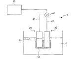
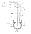
- FIG. 1 is a diagram showing an outline of the entire configuration of an oil deterioration sensor according to an embodiment.
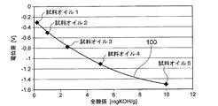
- FIG. 2 is a graph showing the relationship between the potential difference between the sensitive electrode and the reference electrode of the oil deterioration sensor and the total acid value of the oil.
- the oil deterioration sensor 1 includes a sensitive electrode 20 having a sensitive portion 21, a comparative electrode 30, and a potentiometer 40 capable of detecting a potential difference between the sensitive electrode 20 and the comparative electrode 30.
- the measurement principle of the oil deterioration sensor 1 is that the ionic liquid film is electrically communicated with a sensitive electrode having a sensitive part covered at least in part by the ionic liquid film in a state where the ionic liquid film is immersed in a nonpolar liquid. This is based on the knowledge of the present inventor that a potential difference corresponding to the amount of the polar substance existing in the ionic liquid film is generated between the reference electrode and the reference electrode.
- the oil deterioration sensor 1 according to the embodiment includes an ionic liquid film 10 that can at least partially contact the oil 2 when the deterioration of the oil 2 is detected. And the ionic liquid film
- membrane 10 is provided so that at least one part of the sensitive part 21 of the sensitive electrode 20 may be covered.
- the reference electrode 30 is in electrical communication with the ionic liquid film 10.
- the oil deterioration sensor 1 having the above configuration, since the ionic liquid film 10 can contact the oil 2 to be measured, when the oil deterioration sensor 1 is immersed in the oil 2, the oil 2 is deteriorated due to the deterioration of the oil 2.
- the polar substance generated in the step moves into the ionic liquid film 10 via the interface between the oil 2 and the ionic liquid film 10. Since the ionic liquid film 10 covers at least a part of the sensitive portion 21 of the sensitive electrode 20 and the comparative electrode 30 is electrically connected to the ionic liquid film 10, the sensitive electrode 20 and the comparative electrode 30. A potential difference corresponding to the amount of the polar substance existing in the ionic liquid film 10 is generated between the two.
- the degree of deterioration of the oil 2 can be detected from the potential difference.
- the above-described measurement principle of the oil deterioration sensor 1 can be established even if the liquid to be measured is non-polar. Therefore, the oil deterioration sensor 1 uses the oil 2 that has not been subjected to operations such as dissolution and dilution as it is. Even if it can be used.
- the sensitive portion 21 of the sensitive electrode 20 is configured to be sensitive to movement of polar substances generated in the oil 2 due to deterioration of the oil 2 to the ionic liquid film 10.
- polar substances generated in the oil 2 due to deterioration of the oil 2 to the ionic liquid film 10.
- organic acids such as carboxylic acid, and a sulfuric acid can be mentioned, for example.
- the specific configuration of the sensitive electrode 20 will be described in detail later with reference to FIGS.
- the comparison electrode 30 is electrically connected to the ionic liquid film 10 that covers the sensitive portion 21 of the sensitive electrode 20.
- the comparison electrode 30 is in electrical communication with the ionic liquid film 10 by directly contacting the ionic liquid film 10 covering the sensitive portion 21 of the sensitive electrode 20, as shown in FIG. .
- the reference electrode 30 is formed by using an electrode solution of the sensitive electrode 20 via an electrolyte solution such as an aqueous solution of potassium chloride or an aqueous solution of sodium chloride, or a solid made of a conductor such as an electrically conductive metal or an electrically conductive resin.
- the ionic liquid film 10 covering the sensitive part 21 is electrically communicated.
- the specific configuration of the comparison electrode 30 will be described in detail later with reference to FIGS.
- the potentiometer 40 is not particularly limited as long as the potential difference between the sensitive electrode 20 and the comparison electrode 30 can be measured.
- one potentiometer 40 is connected to the sensitive electrode 20 via a conductive wire 41.
- a voltmeter in which the terminal is connected and the other terminal is connected to the comparison electrode 30 through the conducting wire 42 can be used.
- the oil deterioration sensor 1 includes a deterioration determination unit 50 for determining the degree of deterioration of the oil 2 to be measured based on the potential difference obtained by the potentiometer 40.
- the deterioration determination unit 50 includes a storage unit in which a correlation between the potential difference between the sensitive electrode 20 and the comparison electrode 30 and the degree of oil deterioration is stored, and by applying a measurement value by the potentiometer 40 to the correlation.
- the deterioration degree of the oil 2 may be determined.
- the correlation stored in the storage unit may be acquired in advance using sample oil whose degradation degree is known.
- the relationship between the potential difference between the sensitive electrode 20 and the comparison electrode 30 and the total acid value of the oil is acquired in advance using sample oil and stored in the storage unit of the deterioration determination unit 50.
- the deterioration determination unit 50 can determine the degree of deterioration of the oil 2 by applying the measured value of the potentiometer 40 to the relationship and estimating the total acid value of the oil 2.
- the deterioration determination unit 50 may have an output unit (not shown) for outputting the determination result of the deterioration degree of the oil 2.
- the ionic liquid contained in the ionic liquid film 10 is a salt that exists as a liquid in an environment where oil deterioration is detected.
- the ionic liquid of the ionic liquid film 10 is an ionic liquid that exists as a liquid within a temperature range of t 0 ⁇ 20 ⁇ t ⁇ t 0 +100, where t 0 [° C.] is a temperature at which oil deterioration is detected. It may be.
- the ionic liquid of the ionic liquid film 10 may be insoluble in oil.
- the ionic liquid has a property of not substantially dissolving in the oil 2 to be measured.
- the salt of an ionic liquid can be comprised by the combination of various cations and anions.
- the cation constituting the salt of the ionic liquid include imidazolium ions, pyridinium ions, pyrazolium ions, piperidinium ions, pyrrolidinium ions, morpholine ions, pyrrole ions, phosphonium ions, and quaternary ammonium ions.
- Examples thereof include at least one selected from the group consisting of ions, sulfonium-based ions, isoxazolium-based ions, and the like.
- the anion constituting the salt of the ionic liquid includes, for example, a phosphinate ion, an imide ion, a carboxylate ion, a phosphate ion, a borate ion, a thiocyanate ion, and a thiosalicylate ion. There may be mentioned at least one selected from the group.
- ionic liquid salts include, for example: Trihexyl-tetradecyl-phosphonium / bis (2,4,4-trimethyl-pentyl) phosphinate, 1-ethyl-3-methyl-imidazolium / bis (pentafluoroethylsulfonyl) imide, 1-butyl-1-methyl-pyrrolidinium / bis (trifluoromethylsulfonyl) imide, Tetrabutyl-ammonium / bis (trifluoromethylsulfonyl) imide, Trihexyl-tetradecyl-phosphonium / decanoate, 1-butyl-3- (3,3,4,4,5,5,6,6,7,7,8,8,8-tridecafluorooctyl) -imidazolium / hexafluorophosphate, 1-methyl-3- (3,3,4,4,5,5,6,6,7,7,8,8,8
- the kinematic viscosity at 40 ° C. of the ionic liquid film 10 is 12 mm 2 / s or more. In this case, even when the oil 2 in a stirring state is a measurement target, the ionic liquid film 10 covering at least a part of the sensitive electrode 20 is easily held on the electrode surface.
- the ionic liquid film 10 may contain a thickener.
- the ionic liquid film 10 When the ionic liquid film 10 contains a thickener, the ionic liquid film 10 enters a grease state or a state equivalent thereto, and the viscosity of the ionic liquid film 10 increases. Therefore, even when the oil 2 in a stirring state is a measurement target, the ionic liquid film 10 can be easily held on the electrode surface.
- the thickener for example, soaps such as calcium soap and lithium soap, urea thickener, polytetrafluoroethylene (PTFE), organic thickener represented by melamine cyanurate (MCA), Alternatively, metals such as copper and silver, metal oxides such as zinc oxide and titanium oxide, nitrides such as boron nitride, and inorganic fine powders such as carbon black can be used.
- the mass may be 3% by mass or 3 to 30% by mass.
- the ionic liquid film 10 may contain fine powder composed of an inorganic substance or an organic substance in place of or in addition to the thickener.
- the ionic liquid film 10 contains an inorganic or organic fine powder, the ionic liquid film 10 becomes semi-solid and the viscosity of the ionic liquid film 10 increases. Therefore, even when the oil 2 in a stirring state is a measurement target, the ionic liquid film 10 can be easily held on the electrode surface.
- fine powders made of inorganic or organic materials include metal oxides such as zinc oxide and titanium oxide, ceramics such as alumina and silicon nitride, nitrides such as boron nitride, and fluorine resins such as PTFE.
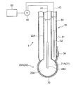
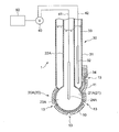
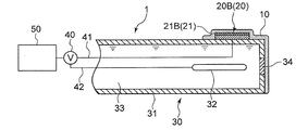
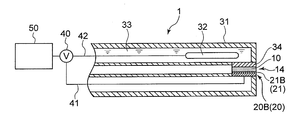
- FIGS. 3 to 5 are schematic sectional views showing an oil deterioration sensor using a glass electrode according to the embodiment.
- 6 to 9 are schematic cross-sectional views showing an oil deterioration sensor using an ISFET electrode.
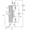
- FIG. 10 is a diagram illustrating a schematic configuration of an ISFET electrode in some embodiments.
- the sensitive portion 21 of the sensitive electrode 20 is configured to be sensitive to changes in the hydrogen ion concentration in the ionic liquid film 10 as the polar substance moves from the oil 2 to the ionic liquid film 10. Is done.
- Examples of the sensitive portion 21 having such a configuration include the glass thin film 21A of the glass electrode 20A shown in FIGS. 3 to 5 and the ion sensitive film 21B of the ISFET electrode 20B shown in FIGS. .
- the sensitive electrode 20 is a glass electrode 20 ⁇ / b> A having a glass thin film 21 ⁇ / b> A as the sensitive portion 21.
- the glass thin film 21 ⁇ / b> A as the sensitive portion 21 is sensitive to a change in the hydrogen ion concentration in the ionic liquid film 10 due to the movement of the polar substance from the oil 2 to the ionic liquid film 10, and is compared with the sensitive electrode 20.
- a potential difference corresponding to the hydrogen ion concentration is formed between the electrode 30 and the electrode 30.
- the glass electrode 20A as the sensitive electrode 20 is provided with an insulating glass electrode support tube 22A and a tip of the glass electrode support tube 22A.
- the internal electrode 23 for example, a silver / silver chloride electrode is used.
- a buffer solution containing potassium chloride having a constant pH of about 7 can be used. In the exemplary embodiment shown in FIGS.
- the comparison electrode 30 is provided on the outer peripheral side of the glass electrode 20 ⁇ / b> A as the sensitive electrode 20.
- an annular comparison electrode support tube 31 of the comparison electrode 30 is provided so as to surround the glass electrode support tube 22A of the glass electrode 20A.
- the comparison electrode 30 may be provided on the inner peripheral side of the glass electrode 20 ⁇ / b> A as the sensitive electrode 20.
- an annular glass electrode support tube 22A of the glass electrode 20A may be provided so as to surround the comparison electrode support tube 31 of the comparison electrode 30.
- the sensitive electrode 20 is an ion sensitive field effect transistor (ISFET) electrode 20B having an ion sensitive membrane (ISM) 21B (see FIG. 10) as the sensitive portion 21. is there.
- ISFET ion sensitive field effect transistor
- the ion sensitive film 21B as the sensitive part 21 is sensitive to a change in the hydrogen ion concentration in the ionic liquid film 10 accompanying the movement of the polar substance from the oil 2 to the ionic liquid film 10, and a drain current which will be described later. Id is affected.
- the ISFET electrode 20B as the sensitive electrode 20 includes an ion sensitive portion 21 as a sensitive portion 21 provided on the semiconductor substrate 60 via the semiconductor substrate 60 and the insulating layer 25, as shown in FIG.
- the semiconductor substrate 60 includes a P-type semiconductor portion 27 and a pair of N-type semiconductor portions 26 (26S, 26D) provided on the P-type semiconductor portion 27.
- the pair of N-type semiconductor portions 26 (26S, 26D) correspond to the source 26S and the drain 26D of the ion-sensitive field effect transistor, respectively.
- the source 26S and the drain 26D are disposed with a channel region 28 therebetween.
- the ion sensitive film 21B is insulated from the semiconductor substrate 60 by the insulating layer 25B.
- the potentiometer 40 is connected to the source 26S of the ISFET electrode 20B via the lead 41 and compared via the lead 42. Connected to the electrode 30.
- the ISFET electrode 20 ⁇ / b> B as the sensitive electrode 20 is disposed on the outer peripheral surface of the comparison electrode support tube 31 of the comparison electrode 30.
- the ISFET electrode 20B as the sensitive electrode 20 is fitted into the hole provided in the comparison electrode support tube 31.
- the measurement principle of the oil deterioration sensor 1 provided with the ISFET electrode 20B in one embodiment is as follows.
- the current (drain current I d ) flowing between the source 26S and the drain 26D via the channel region 28 is not only the voltage V ds between the source 26S and the drain 26D, but also the ion sensitive contact with the ionic liquid film 10. It also depends on the surface potential of the membrane 21B. This is because the execution gate voltage actually applied to the semiconductor substrate 60 changes as a result of the surface potential of the ion sensitive film 21B changing according to the hydrogen ion concentration in the ionic liquid film 10.
- the potential difference between the source 26S and the comparison electrode 30 measured by the potentiometer 40 in a state where the drain current Id and the source-drain voltage Vds are maintained constant is the hydrogen ion concentration in the ionic liquid film 10. It can be used as an index indicating In this way, the potential difference between the sensitive electrode 20 (ISFET electrode 20B) and the comparison electrode 30 (specifically, the source 26S and the comparison electrode 30) measured by the potentiometer 40 by the oil deterioration sensor 1 provided with the ISFET electrode 20B. The deterioration of the oil 2 can be detected based on the potential difference between the two.
- the ion sensitive film 21B only needs to be sensitive to hydrogen ions, and for example, Si 3 N 4 , Al 2 O 3 or Ta 2 O 5 can be used as the material.
- the comparison electrode 30 includes a comparison electrode support tube 31, a reference electrode portion 32 provided inside the comparison electrode support tube 31, and a reference electrode portion 32.
- the internal liquid 33 with which it fills in the comparison electrode support tube 31, and the liquid junction part 34 provided between the internal liquid 33 and the sample of a measuring object.
- the liquid junction 34 is a portion where the internal liquid 33 and the ionic liquid film 10 are in electrical contact.
- the liquid junction 34 only needs to have a fine hole so that the comparison electrode 30 and the ionic liquid film 10 are in electrical communication.
- a porous material such as alumina or zirconia is used as the material. it can.
- the reference electrode unit 31 may be any electrode that exhibits a constant potential regardless of the hydrogen ion concentration of the sample to be measured.
- a silver / silver chloride electrode is used.
- the internal liquid 32 for example, a potassium chloride solution is used.
- the ionic liquid film 10 includes the sensitive portion 21 (21A, 21B) of the sensitive electrode 20 (20A, 20B) and the liquid junction portion 34 of the comparative electrode 30. And at least partially covering both.
- the ionic liquid film 10 is disposed so as to at least partially cover only the sensitive portion 21 (21A, 21B) of the sensitive electrode 20 (20A, 20B).
- the liquid junction part 34 of the comparison electrode 30 is a solid composed of an electrolyte solution such as a potassium chloride aqueous solution or a sodium chloride aqueous solution, or a conductor such as a conductive metal or a conductive resin. Is electrically connected to the ionic liquid film 10 via the.
- the oil deterioration sensor 1 further includes a protection unit 11 that partially covers the ionic liquid film 10.
- the protection unit 11 is provided between the ionic liquid film 10 and the oil 2. At least a part of the region of the ionic liquid film 10 that is not covered by the protection unit 11 is in contact with the oil 2.
- the protection part 11 that covers the ionic liquid film 10 the outflow of the ionic liquid film 10 that covers the sensitive part 21 (21A, 21B) of the sensitive electrode 20 (20A, 20B) to the oil 2 can be reduced.
- the shape of the protection part 11 is not particularly limited, and can be maintained such that the ionic liquid 10 covers the sensitive electrode 20 by being arranged outside the sensitive electrode 20 covered by the ionic liquid 10 such as a plate shape. Any shape is acceptable.
- the material of the protection part 11 should just be a thing which does not melt
- the glass electrode 20A and the glass electrode support are interposed between the ionic liquid 10 and the oil 2 covering the comparison electrode 30 formed around the spherical glass electrode 20A and the glass electrode support tube 22A.
- a protection part 11 having a shape surrounding a part of the tube 22A is provided.
- a plate-like protection unit 11 is provided between the plate-like ionic liquid 10 and the oil 2.
- a region where the ionic liquid film 10 is not covered with the protective part 11 is formed by at least one opening 13 provided in the protective part 11.
- the end portion 12 of the ionic liquid film 10 is not covered by the protective portion 11, thereby forming a region where the ionic liquid film 10 is not covered by the protective portion 11. .
- the sensitive part 21 (21A, 21B) and the liquid junction part 34 are arranged on both sides of the ionic liquid film 10 so as to sandwich the ionic liquid film. .
- a part of the ionic liquid film 10 can contact the oil 2 without being covered by the sensitive part 21 (21A, 21B) and the liquid junction part 34. Since the ionic liquid film 10 is sandwiched between the sensitive part 21 (21A, 21B) and the liquid junction part 34, both side surfaces of the ionic liquid film 10 are not in contact with the oil 2, so that the oil 2 of the ionic liquid film 10 Can be reduced. Moreover, since a part of the ionic liquid film 10 is not covered with the sensitive part 21 (21A, 21B) and the liquid junction part 34 and can contact the oil 2, the contact between the ionic liquid film 10 and the oil 2 is prevented. Secured.
- the ionic liquid film 10 is formed between the glass thin film 21A of the glass electrode 20A and the liquid junction part 34 of the comparison electrode 30 provided so as to surround the glass thin film 21A.
- the portion 29 covering the bottom of the glass electrode 20 ⁇ / b> A is not covered with the glass thin film 21 ⁇ / b> A and the liquid junction 34, and can contact the oil 2.
- the ion sensitive film 21B of the ISFET electrode 20B and the liquid junction 34 of the comparison electrode 30 are opposed to each other, and the ionic liquid film 10 is formed in the space between them. Further, the end surface 14 of the ionic liquid film 10 is not covered with the ion sensitive film 21 ⁇ / b> B and the liquid junction 34, and can contact the oil 2.
- an oil deterioration detection method That is, a method for measuring the potential difference between the sensitive electrode 20 and the comparison electrode 30 with the potentiometer 40 using the oil deterioration sensor 1 and detecting the deterioration of the oil 2 based on the measurement result of the potentiometer 40 will be described. .
- the relationship between the potential difference between the sensitive electrode and the reference electrode and the total acid value of the oil using the sample oil whose content of the acidic component is known (see FIG. 2) Ask for.
- the potential difference between the sensitive electrode 20 and the reference electrode 30 of the oil deterioration sensor 1 is measured by the potentiometer 40 for each of the five types of sample oils (sample oil 1 to sample oil 5 shown in FIG. 2) having different total acid values.
- the oil deterioration sensor 1 is immersed in each sample oil so that the ionic liquid film 10 comes into contact with each sample oil and is sensitive to the movement of polar substances from each sample oil to the ionic liquid film 10.
- the potential difference between the sensitive electrode 20 and the reference electrode 30 is measured. Then, the total acid value (unit: mg KOH / g) is plotted on the horizontal axis, and the measurement result of the potential difference (unit: V) measured at each total acid value is plotted on the vertical axis. For example, comparison with a sensitive electrode as shown in FIG. A relationship between the potential difference from the electrode and the total acid value of the oil (calibration curve 100) is obtained. The relationship (calibration curve 100) between the potential difference between the sensitive electrode and the reference electrode and the total acid value of the oil is stored in the storage unit of the deterioration determination unit 50 of the oil deterioration sensor 1.
- the oil deterioration sensor 1 is immersed in the measurement target oil so that the ionic liquid film 10 contacts the measurement target oil and is sensitive to the movement of the polar substance from the measurement target oil to the ionic liquid film 10. To do. Then, the potential difference between the sensitive electrode 20 and the comparative electrode 30 is measured in a state where the oil deterioration sensor 1 is immersed in the oil to be measured. The deterioration determination unit 50 obtains the total acid value corresponding to the measured potential difference from the relationship between the potential difference between the sensitive electrode and the reference electrode stored in advance and the total acid value of the oil, and the measurement target is obtained based on the total acid value. Determine the deterioration of oil.
- the oil deterioration sensor 1 according to the above-described embodiment was produced, and a test for detecting oil deterioration was performed.
- a pH electrode comprising a glass electrode having a glass thin film and a reference electrode having a liquid junction and configured to exhibit a pH corresponding to a potential difference between the glass electrode and the liquid junction was prepared.
- the oil deterioration sensor shown in FIG. 3 was obtained by forming an ionic liquid film so as to cover the glass thin film of the glass electrode and the liquid junction of the comparative electrode.
- the ionic liquid film was formed using an ionic liquid containing 98% content of an ionic liquid having 1-methyl-3-octyl-imidazolium ions as cations and chlorine ions as anions.
- the oil deterioration sensor obtained as described above was immersed in undegraded engine oil having a total base number of 6.8 mgKOH / g and a total acid number of 1.8 mgKOH / g. At this time, the ionic liquid film of the oil deterioration sensor was brought into contact with the engine oil. Before the start of immersion, the pH indication value of the oil deterioration sensor was 5.7. The pH value indicated by the oil deterioration sensor continued to increase immediately after the start of immersion, and the pH value indicated by the oil deterioration sensor became almost constant at 7.0 after about 4 minutes from the start of immersion.
- the oil deterioration sensor obtained as described above was immersed in a deteriorated engine oil having a total base number of 1.1 mgKOH / g and a total acid number of 4.8 mgKOH / g. At this time, the ionic liquid film of the oil deterioration sensor was brought into contact with the engine oil. Prior to the start of immersion, the pH value indicated by the oil deterioration sensor was 5.9. Immediately after the start of immersion, the pH value indicated by the oil deterioration sensor continued to decrease, and after about 4 minutes from the start of immersion, the pH value indicated by the oil deterioration sensor became substantially constant at 5.0.
- the movement of the polar substance between the oil and the ionic liquid film is in an equilibrium state, and the potential difference corresponding to the deterioration state of the oil is a glass electrode. It was found that a pH value corresponding to this potential difference was obtained between the reference electrode and the reference electrode. From this, the total acid value of the oil is obtained by immersing the oil deterioration sensor in an oil having an unknown total acid number that has not been subjected to operations such as dissolution and dilution, and reading the pH value when the equilibrium state is reached. It was confirmed that oil deterioration can be detected.
Landscapes
- Chemical & Material Sciences (AREA)
- Health & Medical Sciences (AREA)
- Life Sciences & Earth Sciences (AREA)
- Analytical Chemistry (AREA)
- General Health & Medical Sciences (AREA)
- Pathology (AREA)
- Chemical Kinetics & Catalysis (AREA)
- Immunology (AREA)
- General Physics & Mathematics (AREA)
- Physics & Mathematics (AREA)
- Engineering & Computer Science (AREA)
- Biochemistry (AREA)
- Molecular Biology (AREA)
- Electrochemistry (AREA)
- Medicinal Chemistry (AREA)
- Food Science & Technology (AREA)
- General Chemical & Material Sciences (AREA)
- Oil, Petroleum & Natural Gas (AREA)
- Microelectronics & Electronic Packaging (AREA)
- Investigating Or Analyzing Materials By The Use Of Electric Means (AREA)
Abstract
Description
これは、トルエン、2-プロパノールおよび水からなる混合溶剤に試料油を溶かし、pHをモニターしながら塩酸標準2-プロパノール液または水酸化カリウム標準2-プロパノール液で滴定を行うことにより、オイルの劣化の指標とされて一般に用いられる全酸価を求めるものである(非特許文献1を参照)。
全酸価とは、試料油1g中に含まれる酸性成分の全量、すなわち添加剤中の酸性物質、使用中に生成した有機酸などすべてを合せた量を中和するのに要する水酸化カリウムの量であり、一般にオイルが劣化するにしたがって、全酸価は増加するのが通常である。 As a method for detecting deterioration of oil such as lubricating oil, a method described in JIS K2501: 2003 “Petroleum products and lubricating oil-neutralization number test method” has been known.
This is because the sample oil is dissolved in a mixed solvent consisting of toluene, 2-propanol and water, and titration is performed with hydrochloric acid standard 2-propanol solution or potassium hydroxide standard 2-propanol solution while monitoring the pH. The total acid value that is generally used as an index of the above is obtained (see Non-Patent Document 1).
The total acid value is the amount of potassium hydroxide required to neutralize the total amount of acidic components contained in 1 g of sample oil, that is, the total amount of acidic substances in additives and organic acids generated during use. The total acid number generally increases as the oil degrades.
このようなpH電極センサは、試料溶液に浸漬して使用する。ガラス電極のガラス膜が試料溶液と接触すると、ガラス膜の表面が試料溶液のpHに応じた電位差を発生する。この際、一定の基準電位を提示しうる参照電極を用いてこの電位差を測定することで、試料溶液のpHを得ることができる。 On the other hand, a pH electrode sensor including a glass electrode as a pH electrode and a reference electrode is known as an apparatus for measuring the pH of an aqueous solution (see Patent Document 1).
Such a pH electrode sensor is used by being immersed in a sample solution. When the glass film of the glass electrode comes into contact with the sample solution, the surface of the glass film generates a potential difference corresponding to the pH of the sample solution. At this time, the pH of the sample solution can be obtained by measuring this potential difference using a reference electrode capable of presenting a constant reference potential.
イオン液体を含み、前記オイルの劣化検出時に少なくとも部分的に前記オイルに接触可能であるイオン液体膜と、
前記イオン液体膜によって少なくとも一部が覆われ、前記オイルから前記イオン液体膜への前記極性物質の移動に感応するように構成された感応部を有する感応電極と、
前記イオン液体膜に電気的に連通される比較電極と、
前記感応電極と前記比較電極との間の電位差を測定するための電位差計とを備える。 An oil deterioration sensor according to at least one embodiment of the present invention is an oil deterioration sensor that detects a deterioration of the oil by detecting a polar substance generated by the deterioration of the oil,
An ionic liquid film containing an ionic liquid and capable of at least partially contacting the oil when detecting deterioration of the oil;
A sensitive electrode having a sensitive portion that is at least partially covered by the ionic liquid film and configured to be sensitive to movement of the polar substance from the oil to the ionic liquid film;
A reference electrode in electrical communication with the ionic liquid film;
A potentiometer for measuring a potential difference between the sensitive electrode and the reference electrode;
上記オイル劣化センサは、かかる本発明者による知見に基づくものである。すなわち、測定対象のオイルにイオン液体膜が接触可能であるため、上記オイル劣化センサをオイルに浸漬すると、オイルの劣化に起因してオイル内に生じた極性物質がオイルとイオン液体膜との間の界面を介してイオン液体膜内に移動する。そして、このイオン液体膜によって感応電極の感応部の少なくとも一部が覆われ、且つ、イオン液体膜に比較電極が電気的に連通されているため、感応電極と比較電極との間には、イオン液体膜内に存在する極性物質の量に応じた電位差が発生する。この電位差を電位差計で測定することで、該電位差からオイルの劣化度を検出することができる。
また、上記オイル劣化センサの測定原理は、上述したように、測定対象液体が非極性であっても成立し得るから、上記オイル劣化センサは、溶解、希釈等の操作が加えられていないオイルをそのまま測定対象とする場合であっても使用可能である。 As a result of intensive studies, the inventor has developed a sensitive electrode having a sensitive portion at least partially covered with an ionic liquid film in a state where the ionic liquid film is immersed in a nonpolar liquid, and an ionic liquid film electrically It has been found that a potential difference corresponding to the amount of the polar substance existing in the ionic liquid film occurs between the communicating reference electrodes. This is because the polar ionic liquid film is interposed between the nonpolar liquid and the sensitive part of the sensitive electrode, so that the sensitive part can be sensitive to the movement of the polar substance from the nonpolar liquid to the ionic liquid film. It is thought that it was because of it. Since the movement of a polar substance from a nonpolar liquid to an ionic liquid membrane can be described by the equilibrium relationship between the nonpolar liquid and the ionic liquid, the potential difference generated between the sensitive electrode and the reference electrode is the polarity in the nonpolar liquid. It is an indicator of the amount of a substance. Therefore, the polar substance in the nonpolar liquid can be detected from the potential difference generated between the sensitive electrode and the comparison electrode.
The oil deterioration sensor is based on the knowledge of the present inventor. That is, since the ionic liquid film can contact the oil to be measured, when the oil deterioration sensor is immersed in the oil, polar substances generated in the oil due to the deterioration of the oil are between the oil and the ionic liquid film. It moves into the ionic liquid film through the interface. The ionic liquid film covers at least a part of the sensitive part of the sensitive electrode, and the reference electrode is in electrical communication with the ionic liquid film. Therefore, an ion is interposed between the sensitive electrode and the comparative electrode. A potential difference corresponding to the amount of polar substance present in the liquid film is generated. By measuring this potential difference with a potentiometer, the degree of deterioration of the oil can be detected from the potential difference.
Further, as described above, the measurement principle of the oil deterioration sensor can be established even when the liquid to be measured is non-polar. Therefore, the oil deterioration sensor uses oil that has not been subjected to operations such as dissolution and dilution. Even if it is used as it is as a measurement object, it can be used.
この場合、オイル劣化センサのオイルへの浸漬時、感応電極の感応部が水素イオン濃度の変化に感応し、オイルの劣化に伴い生成する有機酸等の酸性物質の濃度に応じた電位差が感応電極と基準電極との間に発生する。よって、この電位差を電位差計で測定することにより、オイルの劣化を検出することができる。 In some embodiments, the sensitive part may be configured to be sensitive to a change in the hydrogen ion concentration in the ionic liquid film accompanying movement of the polar substance from the oil to the ionic liquid film. .
In this case, when the oil deterioration sensor is immersed in the oil, the sensitive part of the sensitive electrode is sensitive to changes in the hydrogen ion concentration, and a potential difference corresponding to the concentration of an acidic substance such as an organic acid generated as the oil deteriorates. And between the reference electrode and the reference electrode. Therefore, the deterioration of the oil can be detected by measuring this potential difference with a potentiometer.
イオン液体膜が感応部と液絡部の両方が少なくとも部分的に覆うことにより、感応電極と比較電極との直接的な電気的連通状態をイオン液体膜によって形成できる。 In some embodiments, the ionic liquid film may be arranged so as to at least partially cover both the sensitive part and the liquid junction part.
By directly covering both the sensitive part and the liquid junction part with the ionic liquid film, a direct electrical communication between the sensitive electrode and the reference electrode can be formed by the ionic liquid film.
前記イオン液体膜は、前記保護部によって覆われていない領域の少なくとも一部が前記オイルと接触するように構成されていてもよい。
オイル劣化センサが浸漬される試料オイルが撹拌状態にあると、感応電極等を覆うイオン液体膜の全部または一部が流去される場合がある。そこで、上述の実施形態のように、イオン液体膜を部分的に覆う保護部を設けるとともに、イオン液体膜の少なくとも一部を保護部で覆わずにオイルに接触させることで、オイル中の極性物質のイオン液体膜への移動を確保しつつ、イオン液体膜のオイルへの流出を低減することができる。 In some embodiments, the oil deterioration sensor further includes a protection part that is provided between the ionic liquid film and the oil and partially covers the ionic liquid film,
The ionic liquid film may be configured such that at least a part of a region that is not covered by the protective portion is in contact with the oil.
If the sample oil in which the oil deterioration sensor is immersed is in a stirring state, all or part of the ionic liquid film covering the sensitive electrode or the like may be washed away. Therefore, as in the above-described embodiment, a protective part that partially covers the ionic liquid film is provided, and at least a part of the ionic liquid film is not covered with the protective part, so that the polar substance in the oil is brought into contact with the oil. The movement of the ionic liquid film to the oil can be reduced while ensuring the movement of the ionic liquid film to the ionic liquid film.
前記イオン液体膜の一部は、前記感応部及び前記液絡部には覆われずに前記オイルに接触可能であってもよい。
このように、イオン液体膜を感応部と液絡部とで挟むことで、イオン液体膜の両方の側面がオイルに接しないこととなるため、イオン液体膜のオイルへの流出を低減することができる。また、イオン液体膜の一部はオイルに接触可能であるため、オイル中の極性物質のイオン液体膜への移動を確保することができる。 In some embodiments, the sensitive part and the liquid junction part are disposed on both sides of the ionic liquid film so as to sandwich the ionic liquid film,
A part of the ionic liquid film may be in contact with the oil without being covered with the sensitive part and the liquid junction part.
Thus, by sandwiching the ionic liquid film between the sensitive part and the liquid junction part, both sides of the ionic liquid film are not in contact with the oil, so that the outflow of the ionic liquid film to the oil can be reduced. it can. Moreover, since a part of ionic liquid film | membrane can contact oil, the movement to the ionic liquid film | membrane of the polar substance in oil can be ensured.
イオン液体膜の粘度を増加させることにより、イオン液体膜のオイルへの流出を低減させることができる。 In some embodiments, the ionic liquid film may have a kinematic viscosity at 40 ° C. of 12 mm 2 / s or more.
By increasing the viscosity of the ionic liquid film, the outflow of the ionic liquid film to the oil can be reduced.
イオン液体膜が増ちょう剤を含むことで、イオン液体膜の粘度を増加させることができ、これによりイオン液体膜のオイルへの流出を低減させることができる。
なお、イオン液体膜に対する増ちょう剤の含有量C(=x/y。ただし、xは増ちょう剤の添加量であり、yはイオン液体膜全体としての質量である。)は、1~50質量%であってもよい。 In some embodiments, the ionic liquid film may include a thickener.
When the ionic liquid film contains the thickener, the viscosity of the ionic liquid film can be increased, and thereby the outflow of the ionic liquid film to the oil can be reduced.
The content C of the thickener relative to the ionic liquid membrane (= x / y, where x is the addition amount of the thickener and y is the mass of the ionic liquid membrane as a whole) is 1 to 50. It may be mass%.
前記オイルに前記イオン液体膜が少なくとも部分的に接触し、前記オイルから前記イオン液体膜への前記極性物質の移動に感応するように、前記オイル劣化センサを前記オイルに浸漬する浸漬ステップと、
前記オイル劣化センサを前記オイルに浸漬した状態で、前記感応電極と前記比較電極との間の電位差を計測する計測ステップと、
前記電位差に基づいて、前記オイルの劣化を検出する劣化検出ステップとを備える。 An oil deterioration detection method according to at least one embodiment of the present invention includes an ionic liquid film containing an ionic liquid, a sensitive electrode having a sensitive part covered at least in part by the ionic liquid film, and an electric current applied to the ionic liquid film. An oil deterioration detection method comprising detecting an oil deterioration by detecting a polar substance generated by oil deterioration using an oil deterioration sensor comprising a reference electrode that is communicated with the oil,
An immersing step of immersing the oil degradation sensor in the oil such that the ionic liquid film is at least partially in contact with the oil and sensitive to movement of the polar substance from the oil to the ionic liquid film;
In a state where the oil deterioration sensor is immersed in the oil, a measurement step of measuring a potential difference between the sensitive electrode and the comparison electrode;
A deterioration detecting step of detecting deterioration of the oil based on the potential difference.
この測定原理を実現するために、実施形態にかかるオイル劣化センサ1は、オイル2の劣化検出時に少なくとも部分的にオイル2に接触可能なイオン液体膜10を備える。そして、イオン液体膜10は、感応電極20の感応部21の少なくとも一部を覆うように設ける。一方、比較電極30は、イオン液体膜10に電気的に連通させる。 The measurement principle of the
In order to realize this measurement principle, the
オイル劣化センサ1の上記測定原理は、測定対象液体が非極性であっても成立し得るから、オイル劣化センサ1は、溶解、希釈等の操作が加えられていないオイル2をそのまま測定対象とする場合であっても使用可能である。 According to the
The above-described measurement principle of the
感応電極20の具体的構成については、図3~図9を参照しながら後で詳述する。 In some embodiments, the
The specific configuration of the
幾つかの実施形態では、比較電極30は、図1に示すように、感応電極20の感応部21を覆うイオン液体膜10に直接接触することにより、イオン液体膜10と電気的に連通される。他の実施形態では、比較電極30は、例えば、塩化カリウム水溶液や塩化ナトリウム水溶液等の電解質溶液や、導電性金属や導電性樹脂等の導電体で構成される固体を介して、感応電極20の感応部21を覆うイオン液体膜10に電気的に連通される。
比較電極30の具体的構成については、図3~図9を参照しながら後で詳述する。 The
In some embodiments, the
The specific configuration of the
劣化判定部50は、感応電極20と比較電極30との電位差とオイル劣化度との相関関係が記憶された記憶部を有しており、該相関関係に電位差計40による測定値を当てはめることで、オイル2の劣化度を判定するように構成されていてもよい。この場合、記憶部に記憶される前記相関関係は、劣化度が既知である試料オイルを用いて予め取得されたものであってもよい。例えば、試料オイルを用いて感応電極20と比較電極30との電位差とオイルの全酸価との関係(例えば図2に示す校正曲線100)を予め取得し、劣化判定部50の記憶部に記憶しておけば、劣化判定部50は、電位差計40の測定値を前記関係に当てはめてオイル2の全酸価を推定することでオイル2の劣化度を判定可能である。なお、劣化判定部50は、オイル2の劣化度の判定結果を出力するための不図示の出力部を有していてもよい。 In some embodiments, the
The
イオン液体の塩を構成するカチオンとしては、例えば、イミダゾリウム系イオン、ピリジニウム系イオン、ピラゾリウム系イオン、ピペリジニウム系イオン、ピロリジニウム系イオン、モルホリン系イオン、ピロール系イオン、ホスホニウム系イオン、第四級アンモニウムイオン、スルホニウム系イオン、及びイソオキサゾリウム系イオン等からなる群から選択される少なくとも1つが挙げられる。
一方、イオン液体の塩を構成するアニオンとしては、例えば、フォスフィネート系イオン、イミド系イオン、カルボン酸イオン、フォスフェート系イオン、ボレート系イオン、チオシアネート系イオン、及びチオサリシレート系イオン等からなる群から選択される少なくとも1つが挙げられる。 The salt of an ionic liquid can be comprised by the combination of various cations and anions.
Examples of the cation constituting the salt of the ionic liquid include imidazolium ions, pyridinium ions, pyrazolium ions, piperidinium ions, pyrrolidinium ions, morpholine ions, pyrrole ions, phosphonium ions, and quaternary ammonium ions. Examples thereof include at least one selected from the group consisting of ions, sulfonium-based ions, isoxazolium-based ions, and the like.
On the other hand, the anion constituting the salt of the ionic liquid includes, for example, a phosphinate ion, an imide ion, a carboxylate ion, a phosphate ion, a borate ion, a thiocyanate ion, and a thiosalicylate ion. There may be mentioned at least one selected from the group.
Trihexyl-tetradecyl-phosphonium/bis(2,4,4-trimethyl-pentyl)phosphinate、
1-ethyl-3-methyl-imidazolium/bis(pentafluoroethylsulfonyl)imide、
1-butyl-1-methyl-pyrrolidinium/bis(trifluoromethylsulfonyl)imide、
Tetrabutyl-ammonium/bis(trifluoromethylsulfonyl)imide、
Trihexyl-tetradecyl-phosphonium/decanoate、
1-butyl-3-(3,3,4,4,5,5,6,6,7,7,8,8,8-tridecafluorooctyl)-imidazolium/hexafluorophosphate、
1-methyl-3-(3,3,4,4,5,5,6,6,7,7,8,8,8-tridecafluorooctyl)-imidazolium/hexafluorophosphate、
1-ethyl-3-methyl-imidazolium/hexafluorophosphate、
1-butyl-3-methyl-imidazolium/hexafluorophosphate、
1-hexyl-4-methyl-imidazolium/hexafluorophosphate、
1-butyl-4-methyl-pyridinium/hexafluorophosphate、
1-methyl-3-octyl-imidazolium/hexafluorophosphate、
Trihexyl-tetradecyl-phosphonium/hexafluorophosphate、
Tetrabutyl-ammonium/nonafluoro-butanesulfonate、
Tetrabutyl-ammonium/heptadecafluoro-octanesulfonate、
Tetrabutyl-phosphonium/tetrafluoroborate、
Tetrahexyl-ammonium/tetrafluoroborate、
Tetrapentyl-ammonium/thiocyanate、
Trioctylmethylammonium/thiosalicylate、又は
1-hexyl-3-methyl-imidazolium/trifluoromethansulfonate等が挙げられる。 Specific examples of ionic liquid salts (cations / anions) include, for example:
Trihexyl-tetradecyl-phosphonium / bis (2,4,4-trimethyl-pentyl) phosphinate,
1-ethyl-3-methyl-imidazolium / bis (pentafluoroethylsulfonyl) imide,
1-butyl-1-methyl-pyrrolidinium / bis (trifluoromethylsulfonyl) imide,
Tetrabutyl-ammonium / bis (trifluoromethylsulfonyl) imide,
Trihexyl-tetradecyl-phosphonium / decanoate,
1-butyl-3- (3,3,4,4,5,5,6,6,7,7,8,8,8-tridecafluorooctyl) -imidazolium / hexafluorophosphate,
1-methyl-3- (3,3,4,4,5,5,6,6,7,7,8,8,8-tridecafluorooctyl) -imidazolium / hexafluorophosphate,
1-ethyl-3-methyl-imidazolium / hexafluorophosphate,
1-butyl-3-methyl-imidazolium / hexafluorophosphate,
1-hexyl-4-methyl-imidazolium / hexafluorophosphate,
1-butyl-4-methyl-pyridinium / hexafluorophosphate,
1-methyl-3-octyl-imidazolium / hexafluorophosphate,
Trihexyl-tetradecyl-phosphonium / hexafluorophosphate,
Tetrabutyl-ammonium / nonafluoro-butanesulfonate,
Tetrabutyl-ammonium / heptadecafluoro-octanesulfonate,
Tetrabutyl-phosphonium / tetrafluoroborate,
Tetrahexyl-ammonium / tetrafluoroborate,
Tetrapentyl-ammonium / thiocyanate,
Trioctylmethylammonium / thiosalicylate, or
Examples thereof include 1-hexyl-3-methyl-imidazolium / trifluoromethansulfonate.
イオン液体膜10が増ちょう剤を含有する場合、該イオン液体膜10がグリース状態又はこれに準ずる状態となり、イオン液体膜10の粘度が増大する。よって、撹拌状態にあるオイル2を測定対象とする場合であっても、イオン液体膜10を電極表面に保持しやすくなる。 The
When the
なお、イオン液体膜に対する増ちょう剤の含有量C(=x/y。ただし、xは増ちょう剤の添加量であり、yはイオン液体膜全体としての質量である。)は、1~50質量%であってもよく、3~30質量%であってもよい。 As the thickener, for example, soaps such as calcium soap and lithium soap, urea thickener, polytetrafluoroethylene (PTFE), organic thickener represented by melamine cyanurate (MCA), Alternatively, metals such as copper and silver, metal oxides such as zinc oxide and titanium oxide, nitrides such as boron nitride, and inorganic fine powders such as carbon black can be used.
The content C of the thickener relative to the ionic liquid membrane (= x / y, where x is the addition amount of the thickener and y is the mass of the ionic liquid membrane as a whole) is 1 to 50. The mass may be 3% by mass or 3 to 30% by mass.
イオン液体膜10が無機物又は有機物の微粉末を含有する場合、イオン液体膜10を半固体状となり、イオン液体膜10の粘度が増大する。よって、撹拌状態にあるオイル2を測定対象とする場合であっても、イオン液体膜10を電極表面に保持しやすくなる。 Further, the
When the
図3~図5は、実施形態に係る、ガラス電極を用いたオイル劣化センサを示す概略断面図である。図6~図9は、ISFET電極を用いたオイル劣化センサを示す概略断面図である。図10は、いくつかの実施形態におけるISFET電極の構成の概略を示す図である。 Next, a specific configuration of the
3 to 5 are schematic sectional views showing an oil deterioration sensor using a glass electrode according to the embodiment. 6 to 9 are schematic cross-sectional views showing an oil deterioration sensor using an ISFET electrode. FIG. 10 is a diagram illustrating a schematic configuration of an ISFET electrode in some embodiments.
また、図3~図5に示す例示的な実施形態では、感応電極20としてのガラス電極20Aは、絶縁性のガラス電極支持管22Aと、ガラス電極支持管22Aの先端部に設けられて水素イオン濃度の変化に応答するガラス薄膜21Aと、ガラス電極支持管22A内に充填されたガラス電極内部液23Aと、ガラス電極内部液23Aに浸漬されるようにガラス電極支持管22A内に設けられた内部電極24Aとを備える。内部電極23としては、例えば、銀・塩化銀電極が用いられる。ガラス電極内部液24としては、例えば、pHが7程度で一定の、塩化カリウムを含む緩衝溶液が用いることができる。
なお、図3~図5に示す例示的な実施形態では、比較電極30は、感応電極20としてのガラス電極20Aの外周側に設けられる。具体的には、ガラス電極20Aのガラス電極支持管22Aを取り囲むように、比較電極30の環状の比較電極支持管31が設けられる。他の実施形態では、比較電極30は、感応電極20としてのガラス電極20Aの内周側に設けてもよい。例えば、比較電極30の比較電極支持管31を取り囲むように、ガラス電極20Aの環状のガラス電極支持管22Aが設けられてもよい。 In the exemplary embodiment shown in FIGS. 3 to 5, the
In the exemplary embodiment shown in FIGS. 3 to 5, the
In the exemplary embodiment shown in FIGS. 3 to 5, the
いくつかの実施形態では、感応電極20としてのISFET電極20Bは、図10に示すように、半導体基板60と、絶縁層25を介して半導体基板60上に設けられた感応部21としてのイオン感応膜21Bとを備える。半導体基板60は、P型半導体部分27と、P型半導体部分27上に設けられた一対のN型半導体部分26(26S,26D)とを含む。一対のN型半導体部分26(26S,26D)は、それぞれ、イオン感応型電界効果トランジスタのソース26Sとドレイン26Dに相当する。ソース26Sとドレイン26Dは、チャネル領域28を隔てて配置される。イオン感応膜21Bは、絶縁層25Bにより半導体基板60から絶縁される。なお、上記構成のISFET電極20Bを感応電極20として用いたオイル劣化センサ1の場合、電位差計40は、導線41を介してISFET電極20Bのソース26Sに接続されるとともに、導線42を介して比較電極30に接続される。
なお、図6に示す例示的な実施形態では、比較電極30の比較電極支持管31の外周面上に、感応電極20としてのISFET電極20Bが配置される。また、図7~図9に示す例示的な実施形態では、比較電極支持管31に設けられた孔に、感応電極20としてのISFET電極20Bが嵌め込まれている。 In the exemplary embodiment shown in FIGS. 6-9, the
In some embodiments, the
In the exemplary embodiment shown in FIG. 6, the
チャネル領域28を介してソース26Sとドレイン26Dとの間を流れる電流(ドレイン電流Id)は、ソース26Sとドレイン26Dとの間の電圧Vdsだけでなく、イオン液体膜10に接触するイオン感応膜21Bの表面電位にも依存する。これは、イオン液体膜10内における水素イオン濃度に応じてイオン感応膜21Bの表面電位が変化する結果、半導体基板60に実際に加わる実行ゲート電圧が変化するためである。そのため、ドレイン電流Idおよびソース-ドレイン間電圧Vdsを一定に維持した状態で電位差計40によって計測されるソース26Sと比較電極30との間の電位差は、イオン液体膜10内における水素イオン濃度を示す指標として使用可能である。こうして、ISFET電極20Bを備えたオイル劣化センサ1によって、電位差計40によって計測される感応電極20(ISFET電極20B)と比較電極30との間の電位差(具体的には、ソース26Sと比較電極30との間の電位差)に基づいて、オイル2の劣化を検出することができる。
イオン感応膜21Bは、水素イオンに感応するものであればよく、その材料としては、例えばSi3N4、Al2O3又はTa2O5等を用いることができる。 The measurement principle of the
The current (drain current I d ) flowing between the
The ion
液絡部34は、比較電極30とイオン液体膜10とが電気的に連通するように微細な穴を有するものであればよく、例えば、アルミナやジルコニアなどの多孔性材料を材料として用いることができる。
基準電極部31としては、測定対象の試料の水素イオン濃度にかかわらず一定の電位を示す電極であればよく、例えば、銀・塩化銀電極が用いられる。
内部液32としては、例えば、塩化カリウム溶液が用いられる。 In some embodiments, as shown in FIGS. 3 to 9, the
The
The
As the
他の実施形態では、イオン液体膜10は、感応電極20(20A,20B)の感応部21(21A,21B)のみを少なくとも部分的に覆うように配置される。この場合、イオン液体膜10は、比較電極30の液絡部34は、例えば、塩化カリウム水溶液や塩化ナトリウム水溶液等の電解質溶液や、導電性金属や導電性樹脂等の導電体で構成される固体を介して、イオン液体膜10に電気的に連通される。 In some embodiments, as shown in FIGS. 3 to 9, the
In another embodiment, the
イオン液体膜10を覆う保護部11を設けることで、感応電極20(20A,20B)の感応部21(21A,21B)を覆うイオン液体膜10のオイル2への流出を低減することができる。また、イオン液体膜10のうち保護部11に覆われていない領域の一部がオイル2と接触するので、イオン液体膜10とオイル2との接触が確保される。 In some embodiments, as shown in FIGS. 4, 7, and 8, the
By providing the
保護部11の材料は、保護部11が接触するオイル2やイオン液体膜10に溶解しないものであればよく、多孔質材料等を使用することができる。 The shape of the
The material of the
そして、図4及び図8に示す例示的な実施形態では、保護部11に設けられた少なくとも1つの開口13により、イオン液体膜10が保護部11に覆われない領域が形成される。図7に示す例示的な実施形態では、イオン液体膜10の端部12が保護部11によって覆われない構成とすることにより、イオン液体膜10が保護部11に覆われない領域が形成される。 In the exemplary embodiment shown in FIG. 4, the
In the exemplary embodiment shown in FIGS. 4 and 8, a region where the
イオン液体膜10を感応部21(21A,21B)と液絡部34とで挟むことで、イオン液体膜10の両方の側面がオイル2に接しないこととなるため、イオン液体膜10のオイル2への流出を低減することができる。また、イオン液体膜10の一部は、感応部21(21A,21B)及び液絡部34には覆われずにオイル2に接触可能であるので、イオン液体膜10とオイル2との接触が確保される。 In some embodiments, as shown in FIGS. 5 and 9, the sensitive part 21 (21A, 21B) and the
Since the
図9に示す例示的な実施形態では、ISFET電極20Bのイオン感応膜21Bと、比較電極30の液絡部34とを対向させ、これらの間の空間にイオン液体膜10を形成している。また、イオン液体膜10の端面14は、イオン感応膜21B及び液絡部34には覆われておらず、オイル2に接触可能である。 In the exemplary embodiment shown in FIG. 5, the
In the exemplary embodiment shown in FIG. 9, the ion
全酸価が異なる5種類の試料オイル(図2に示す試料オイル1~試料オイル5)のそれぞれについて、オイル劣化センサ1の感応電極20と基準電極30との間の電位差を電位差計40で計測する。具体的には、各試料オイルに対してイオン液体膜10が接触し、各試料オイルからイオン液体膜10への極性物質の移動に感応するように、上記オイル劣化センサ1を各試料オイルに浸漬した状態で、感応電極20と基準電極30との間の電位差を計測する。そして、横軸に全酸価(単位:mgKOH/g)、縦軸に各全酸価において計測した電位差(単位:V)の計測結果をプロットし、例えば図2に示すような感応電極と比較電極との電位差とオイルの全酸価との関係(校正曲線100)を得る。この感応電極と比較電極との電位差とオイルの全酸価との関係(校正曲線100)を、オイル劣化センサ1の劣化判定部50の記憶部に記憶させておく。
次に、測定対象のオイルに、イオン液体膜10が接触し、測定対象のオイルからイオン液体膜10への極性物質の移動に感応するように、上記オイル劣化センサ1を測定対象のオイルに浸漬する。そして、オイル劣化センサ1を測定対象のオイルに浸漬した状態で、感応電極20と比較電極30との間の電位差を計測する。劣化判定部50は、あらかじめ記憶した上記の感応電極と比較電極との電位差とオイルの全酸価との関係から、計測された電位差に対応する全酸価を求め、この全酸価により測定対象のオイルの劣化を判定する。 First, before measuring the oil to be measured, the relationship between the potential difference between the sensitive electrode and the reference electrode and the total acid value of the oil using the sample oil whose content of the acidic component is known (see FIG. 2) Ask for.
The potential difference between the
Next, the
浸漬開始前にはオイル劣化センサのpH指示値は5.7であった。浸漬開始直後からオイル劣化センサによるpH指示値は増加を続け、浸漬開始から約4分でオイル劣化センサによるpH指示値が7.0でほぼ一定となった。 The oil deterioration sensor obtained as described above was immersed in undegraded engine oil having a total base number of 6.8 mgKOH / g and a total acid number of 1.8 mgKOH / g. At this time, the ionic liquid film of the oil deterioration sensor was brought into contact with the engine oil.
Before the start of immersion, the pH indication value of the oil deterioration sensor was 5.7. The pH value indicated by the oil deterioration sensor continued to increase immediately after the start of immersion, and the pH value indicated by the oil deterioration sensor became almost constant at 7.0 after about 4 minutes from the start of immersion.
浸漬開始前にはオイル劣化センサのpH指示値は5.9であった。浸漬開始直後からオイル劣化センサによるpH指示値は低下を続け、浸漬開始から約4分でオイル劣化センサによるpH指示値が5.0でほぼ一定となった。 The oil deterioration sensor obtained as described above was immersed in a deteriorated engine oil having a total base number of 1.1 mgKOH / g and a total acid number of 4.8 mgKOH / g. At this time, the ionic liquid film of the oil deterioration sensor was brought into contact with the engine oil.
Prior to the start of immersion, the pH value indicated by the oil deterioration sensor was 5.9. Immediately after the start of immersion, the pH value indicated by the oil deterioration sensor continued to decrease, and after about 4 minutes from the start of immersion, the pH value indicated by the oil deterioration sensor became substantially constant at 5.0.
2 オイル
10 イオン液体膜
11 保護部
12 端部
13 開口
14 端面
15 液絡部と接しない部分
20 感応電極
20A ガラス電極
20B ISFET電極
21 感応部
21A ガラス薄膜
22A ガラス電極支持管
23A ガラス電極内部液
24A 内部電極
25B 絶縁層
26S,26D N型半導体部分
27B P型半導体基板
28B チャネル領域
29A ガラス電極底部
30 比較電極
31 比較電極支持管
32 基準電極部
33 内部液
34 液絡部
40 電位差計
41,42 導線
50 劣化判定部 DESCRIPTION OF
Claims (11)
- オイルの劣化により生じる極性物質を検知して前記オイルの劣化を検出するオイル劣化センサであって、
イオン液体を含み、前記オイルの劣化検出時に少なくとも部分的に前記オイルに接触可能であるイオン液体膜と、
前記イオン液体膜によって少なくとも一部が覆われ、前記オイルから前記イオン液体膜への前記極性物質の移動に感応するように構成された感応部を有する感応電極と、
前記イオン液体膜に電気的に連通される比較電極と、
前記感応電極と前記比較電極との間の電位差を測定するための電位差計とを備えることを特徴とするオイル劣化センサ。 An oil deterioration sensor for detecting the deterioration of the oil by detecting a polar substance generated by the deterioration of the oil,
An ionic liquid film containing an ionic liquid and capable of at least partially contacting the oil when detecting deterioration of the oil;
A sensitive electrode having a sensitive portion that is at least partially covered by the ionic liquid film and configured to be sensitive to movement of the polar substance from the oil to the ionic liquid film;
A reference electrode in electrical communication with the ionic liquid film;
An oil deterioration sensor comprising: a potentiometer for measuring a potential difference between the sensitive electrode and the comparison electrode. - 前記感応部は、前記オイルから前記イオン液体膜への前記極性物質の移動に伴う前記イオン液体膜内における水素イオン濃度の変化に感応するように構成されたことを特徴とする請求項1に記載のオイル劣化センサ。 The said sensitive part is comprised so that it might respond to the change of the hydrogen ion concentration in the said ionic liquid film | membrane accompanying the movement of the said polar substance from the said oil to the said ionic liquid film | membrane. Oil deterioration sensor.
- 前記感応電極がガラス電極又はイオン感応性電界効果トランジスタ(ISFET)電極であることを特徴とする請求項2に記載のオイル劣化センサ。 The oil deterioration sensor according to claim 2, wherein the sensitive electrode is a glass electrode or an ion sensitive field effect transistor (ISFET) electrode.
- 前記比較電極は、前記電位差が前記感応電極との間に形成される基準電極部と、前記基準電極部の少なくとも一部が浸漬される内部液と、前記内部液と前記イオン液体膜との間に設けられる液絡部を有することを特徴とする請求項1乃至3のいずれか一項に記載のオイル劣化センサ。 The reference electrode includes a reference electrode part in which the potential difference is formed between the sensitive electrode, an internal liquid in which at least a part of the reference electrode part is immersed, and between the internal liquid and the ionic liquid film. The oil deterioration sensor according to any one of claims 1 to 3, further comprising a liquid junction portion provided on the front surface.
- 前記イオン液体膜は、前記感応部と前記液絡部の両方を少なくとも部分的に覆うように配置されたことを特徴とする請求項4に記載のオイル劣化センサ。 The oil deterioration sensor according to claim 4, wherein the ionic liquid film is disposed so as to at least partially cover both the sensitive part and the liquid junction part.
- 前記イオン液体膜と前記オイルとの間に設けられ、前記イオン液体膜を部分的に覆う保護部をさらに備え、
前記イオン液体膜は、前記保護部によって覆われていない領域の少なくとも一部が前記オイルと接触するように構成された請求項1乃至5のいずれか一項に記載のオイル劣化センサ。 A protective portion provided between the ionic liquid film and the oil, and further partially covering the ionic liquid film;
The oil deterioration sensor according to any one of claims 1 to 5, wherein the ionic liquid film is configured such that at least a part of a region not covered by the protective portion is in contact with the oil. - 前記感応部と前記液絡部とは、前記イオン液体膜を挟むように前記イオン液体膜の両側に配置され、
前記イオン液体膜の一部は、前記感応部及び前記液絡部には覆われずに前記オイルに接触可能であることを特徴とする請求項1乃至5のいずれか一項に記載のオイル劣化センサ。 The sensitive part and the liquid junction part are arranged on both sides of the ionic liquid film so as to sandwich the ionic liquid film,
6. The oil deterioration according to claim 1, wherein a part of the ionic liquid film is not covered with the sensitive part and the liquid junction part and can contact the oil. Sensor. - 前記イオン液体膜の40℃での動粘度が12mm2/s以上であることを特徴とする、請求項1乃至7のいずれか一項に記載のオイル劣化センサ。 8. The oil deterioration sensor according to claim 1, wherein the ionic liquid film has a kinematic viscosity at 40 ° C. of 12 mm 2 / s or more.
- 前記イオン液体膜が、増ちょう剤を含むことを特徴とする、請求項1乃至8のいずれか一項に記載のオイル劣化センサ。 The oil deterioration sensor according to any one of claims 1 to 8, wherein the ionic liquid film contains a thickener.
- 前記イオン液体膜100質量%に対して、前記増ちょう剤の含有量が1~50質量%であることを特徴とする、請求項9に記載のオイル劣化センサ。 10. The oil deterioration sensor according to claim 9, wherein a content of the thickener is 1 to 50% by mass with respect to 100% by mass of the ionic liquid film.
- イオン液体を含むイオン液体膜と、前記イオン液体膜によって少なくとも一部が覆われた感応部を有する感応電極と、前記イオン液体膜に電気的に連通される比較電極とを備えるオイル劣化センサを用いて、オイルの劣化により生じる極性物質を検知して前記オイルの劣化を検出するオイル劣化検出方法であって、
前記オイルに前記イオン液体膜が少なくとも部分的に接触し、前記オイルから前記イオン液体膜への前記極性物質の移動に感応するように、前記オイル劣化センサを前記オイルに浸漬する浸漬ステップと、
前記オイル劣化センサを前記オイルに浸漬した状態で、前記感応電極と前記比較電極との間の電位差を計測する計測ステップと、
前記電位差に基づいて、前記オイルの劣化を検出する劣化検出ステップとを備えることを特徴とするオイル劣化検出方法。
Using an oil deterioration sensor comprising an ionic liquid film containing an ionic liquid, a sensitive electrode having a sensitive part covered at least in part by the ionic liquid film, and a comparison electrode electrically connected to the ionic liquid film An oil deterioration detection method for detecting the deterioration of the oil by detecting a polar substance caused by the deterioration of the oil,
An immersing step of immersing the oil degradation sensor in the oil such that the ionic liquid film is at least partially in contact with the oil and sensitive to movement of the polar substance from the oil to the ionic liquid film;
In a state where the oil deterioration sensor is immersed in the oil, a measurement step of measuring a potential difference between the sensitive electrode and the comparison electrode;
An oil deterioration detection method comprising: a deterioration detection step of detecting deterioration of the oil based on the potential difference.
Priority Applications (2)
| Application Number | Priority Date | Filing Date | Title |
|---|---|---|---|
| KR1020157033812A KR101764050B1 (en) | 2013-06-21 | 2014-06-10 | Oil degradation sensor and oil degradation detection method |
| CN201480026316.6A CN105229456A (en) | 2013-06-21 | 2014-06-10 | The deteriorated sensor of oil and oily degradation detection |
Applications Claiming Priority (2)
| Application Number | Priority Date | Filing Date | Title |
|---|---|---|---|
| JP2013-130735 | 2013-06-21 | ||
| JP2013130735A JP6140001B2 (en) | 2013-06-21 | 2013-06-21 | Oil deterioration sensor and oil deterioration detection method |
Publications (1)
| Publication Number | Publication Date |
|---|---|
| WO2014203764A1 true WO2014203764A1 (en) | 2014-12-24 |
Family
ID=52104502
Family Applications (1)
| Application Number | Title | Priority Date | Filing Date |
|---|---|---|---|
| PCT/JP2014/065293 WO2014203764A1 (en) | 2013-06-21 | 2014-06-10 | Oil degradation sensor and oil degradation detection method |
Country Status (4)
| Country | Link |
|---|---|
| JP (1) | JP6140001B2 (en) |
| KR (1) | KR101764050B1 (en) |
| CN (1) | CN105229456A (en) |
| WO (1) | WO2014203764A1 (en) |
Families Citing this family (4)
| Publication number | Priority date | Publication date | Assignee | Title |
|---|---|---|---|---|
| US10161897B2 (en) * | 2015-01-09 | 2018-12-25 | Xerox Corporation | Sensors incorporating palladium electrodes |
| JP6724632B2 (en) * | 2016-07-28 | 2020-07-15 | いすゞ自動車株式会社 | Diesel engine engine oil deterioration estimation method |
| US10315137B2 (en) * | 2016-11-18 | 2019-06-11 | Caterpillar Inc. | Sensing system for detecting machine fluid degradation |
| CN110095381B (en) * | 2019-05-20 | 2020-10-20 | 安徽江淮汽车集团股份有限公司 | Engine oil dilution detection device and detection method |
Citations (3)
| Publication number | Priority date | Publication date | Assignee | Title |
|---|---|---|---|---|
| JPH06265506A (en) * | 1993-03-15 | 1994-09-22 | Nippondenso Co Ltd | Ph sensor |
| JP2008064578A (en) * | 2006-09-06 | 2008-03-21 | Horiba Ltd | Ionic liquid property measuring method |
| JP2012163506A (en) * | 2011-02-09 | 2012-08-30 | Gunze Ltd | In-oil hydrogen detection sensor |
Family Cites Families (11)
| Publication number | Priority date | Publication date | Assignee | Title |
|---|---|---|---|---|
| JP3118945B2 (en) * | 1992-01-16 | 2000-12-18 | 三菱電機株式会社 | Odor sensor and odor measurement device |
| US5518590A (en) * | 1994-06-21 | 1996-05-21 | Pennzoil Products Company | Electrochemical sensors for motor oils and other lubricants |
| JP2004212174A (en) * | 2002-12-27 | 2004-07-29 | Dkk Toa Corp | METHOD OF pH MEASUREMENT, COMPARISON ELECTRODE, AND MULTIPLE ELECTRODE |
| KR20060087293A (en) * | 2005-01-28 | 2006-08-02 | 한국과학기술원 | Ph-sensor for the measurement of the concentration of the proton in the engine oil to detect the extent of the degradation of the engine oil |
| JP4733588B2 (en) | 2005-08-03 | 2011-07-27 | 国立大学法人京都大学 | Reference electrode, salt bridge and ion concentration measuring device using them |
| JP2007046914A (en) * | 2005-08-05 | 2007-02-22 | Denso Corp | Reference electrode for detecting acidity and basicity of oil |
| JP5036003B2 (en) * | 2006-09-13 | 2012-09-26 | 国立大学法人京都大学 | Ionic liquid-coated reference electrode and electrochemical measurement apparatus using the reference electrode |
| JP5055035B2 (en) | 2007-06-19 | 2012-10-24 | 三菱重工業株式会社 | Oil deterioration detection device |
| WO2012026514A1 (en) * | 2010-08-27 | 2012-03-01 | 株式会社堀場製作所 | Reference electrode |
| JP5356336B2 (en) * | 2010-08-27 | 2013-12-04 | 株式会社堀場製作所 | Reference electrode |
| JP5946782B2 (en) * | 2013-02-22 | 2016-07-06 | 三菱重工業株式会社 | pH sensor and method for detecting oil deterioration using the sensor |
-
2013
- 2013-06-21 JP JP2013130735A patent/JP6140001B2/en active Active
-
2014
- 2014-06-10 WO PCT/JP2014/065293 patent/WO2014203764A1/en active Application Filing
- 2014-06-10 KR KR1020157033812A patent/KR101764050B1/en active IP Right Grant
- 2014-06-10 CN CN201480026316.6A patent/CN105229456A/en active Pending
Patent Citations (3)
| Publication number | Priority date | Publication date | Assignee | Title |
|---|---|---|---|---|
| JPH06265506A (en) * | 1993-03-15 | 1994-09-22 | Nippondenso Co Ltd | Ph sensor |
| JP2008064578A (en) * | 2006-09-06 | 2008-03-21 | Horiba Ltd | Ionic liquid property measuring method |
| JP2012163506A (en) * | 2011-02-09 | 2012-08-30 | Gunze Ltd | In-oil hydrogen detection sensor |
Also Published As
| Publication number | Publication date |
|---|---|
| JP6140001B2 (en) | 2017-05-31 |
| KR101764050B1 (en) | 2017-08-01 |
| JP2015004615A (en) | 2015-01-08 |
| CN105229456A (en) | 2016-01-06 |
| KR20160003158A (en) | 2016-01-08 |
Similar Documents
| Publication | Publication Date | Title |
|---|---|---|
| US5518590A (en) | Electrochemical sensors for motor oils and other lubricants | |
| JP6140001B2 (en) | Oil deterioration sensor and oil deterioration detection method | |
| EP2335061B1 (en) | Reducing capacitive charging in an electrode comprising a heater | |
| US11125714B2 (en) | Potentiometric sensor | |
| EP2952759A1 (en) | Rolling bearing and sensor assembly including the same | |
| US8753495B2 (en) | Electrochemical half cell, electrochemical sensor and method for measuring at least one measured variable of a measured medium with an electrochemical sensor | |
| JP2014052279A (en) | Corrosion potential sensor | |
| Zhao et al. | Floating-Gate Ion Sensitive Field-Effect Transistor for Chemical and Biological Sensing | |
| CN103852508A (en) | Sensor for Registering an Analyte Concentration | |
| CN111788478B (en) | Corrosion measuring device | |
| US9091642B2 (en) | Measuring transducer for determining a measured variable representing an activity of a target ion in a measured medium | |
| CN102841120B (en) | Measure transducer | |
| JP5946782B2 (en) | pH sensor and method for detecting oil deterioration using the sensor | |
| KR102132260B1 (en) | Use of reference system for electrochemical analysis and deposition methods | |
| JP2015004615A5 (en) | ||
| RU2480734C2 (en) | Measuring device of polarisation potential of pipelines | |
| RU2471171C1 (en) | Evaluation device of protection against corrosion as to value of deflection from natural potential | |
| CN103063723B (en) | Solid hydrogen ion concentration electrode based on conductive polyaniline and preparing method thereof | |
| CN112567237A (en) | Potentiometric measuring chain and method for determining pH value | |
| RU2795673C1 (en) | Non-aqueous solution for filling silver chloride reference electrode | |
| CN219830933U (en) | Electrochemical composite sensor | |
| JP2014173928A (en) | Corrosion potential sensor | |
| JP6299230B2 (en) | Cable soundness evaluation method | |
| Branham et al. | Optimization of a robust and reliable ISFET sensor for measuring pH in the deep ocean | |
| Ochoa et al. | Membrane Composition Effects on the Analytical Behavior of Solid Contact Potentiometric Pb2+ Selective Electrodes Based on Diazadibenzo‐18‐crown‐6 Ionophores |
Legal Events
| Date | Code | Title | Description |
|---|---|---|---|
| WWE | Wipo information: entry into national phase |
Ref document number: 201480026316.6 Country of ref document: CN |
|
| 121 | Ep: the epo has been informed by wipo that ep was designated in this application |
Ref document number: 14813445 Country of ref document: EP Kind code of ref document: A1 |
|
| ENP | Entry into the national phase |
Ref document number: 20157033812 Country of ref document: KR Kind code of ref document: A |
|
| NENP | Non-entry into the national phase |
Ref country code: DE |
|
| 122 | Ep: pct application non-entry in european phase |
Ref document number: 14813445 Country of ref document: EP Kind code of ref document: A1 |