WO2014199765A1 - 複眼撮像装置 - Google Patents
複眼撮像装置 Download PDFInfo
- Publication number
- WO2014199765A1 WO2014199765A1 PCT/JP2014/062789 JP2014062789W WO2014199765A1 WO 2014199765 A1 WO2014199765 A1 WO 2014199765A1 JP 2014062789 W JP2014062789 W JP 2014062789W WO 2014199765 A1 WO2014199765 A1 WO 2014199765A1
- Authority
- WO
- WIPO (PCT)
- Prior art keywords
- lens
- light
- final
- shielding
- eye
- Prior art date
- Legal status (The legal status is an assumption and is not a legal conclusion. Google has not performed a legal analysis and makes no representation as to the accuracy of the status listed.)
- Ceased
Links
Images


Classifications
-
- G—PHYSICS
- G02—OPTICS
- G02B—OPTICAL ELEMENTS, SYSTEMS OR APPARATUS
- G02B3/00—Simple or compound lenses
- G02B3/0006—Arrays
- G02B3/0037—Arrays characterized by the distribution or form of lenses
- G02B3/0062—Stacked lens arrays, i.e. refractive surfaces arranged in at least two planes, without structurally separate optical elements in-between
-
- G—PHYSICS
- G02—OPTICS
- G02B—OPTICAL ELEMENTS, SYSTEMS OR APPARATUS
- G02B13/00—Optical objectives specially designed for the purposes specified below
- G02B13/18—Optical objectives specially designed for the purposes specified below with lenses having one or more non-spherical faces, e.g. for reducing geometrical aberration
-
- G—PHYSICS
- G02—OPTICS
- G02B—OPTICAL ELEMENTS, SYSTEMS OR APPARATUS
- G02B5/00—Optical elements other than lenses
- G02B5/20—Filters
- G02B5/208—Filters for use with infrared or ultraviolet radiation, e.g. for separating visible light from infrared and/or ultraviolet radiation
-
- G—PHYSICS
- G02—OPTICS
- G02B—OPTICAL ELEMENTS, SYSTEMS OR APPARATUS
- G02B7/00—Mountings, adjusting means, or light-tight connections, for optical elements
- G02B7/02—Mountings, adjusting means, or light-tight connections, for optical elements for lenses
- G02B7/021—Mountings, adjusting means, or light-tight connections, for optical elements for lenses for more than one lens
-
- G—PHYSICS
- G02—OPTICS
- G02B—OPTICAL ELEMENTS, SYSTEMS OR APPARATUS
- G02B3/00—Simple or compound lenses
- G02B3/0006—Arrays
- G02B3/0075—Arrays characterized by non-optical structures, e.g. having integrated holding or alignment means
Definitions
- the present invention relates to a compound eye imaging apparatus that forms an object image on an imaging device using an array lens composed of a plurality of lenses.
- a compound-eye imaging device using a technique for synthesizing and reconstructing one image by image processing corresponding to each object image formed on the imaging surface is developed.
- a super-resolution technique in which an imaging region is divided by a plurality of single-eye optical systems, and one high-pixel image is reconstructed by image processing from the obtained plurality of low-pixel images.
- the number of lenses used in each single-eye optical system can be reduced, resulting in a high-resolution image while achieving a significantly lower profile than existing optical systems. It is possible to provide a compound eye imaging device.
- an array lens in which a plurality of lenses (single-lens lenses) are integrally formed for each layer is used.
- An array lens in which a plurality of lenses are formed integrally has the advantage that the performance variation of each lens in the array lens can be reduced, and the number of incorporation and formation can be reduced to reduce the cost.
- Patent Document 1 In order to suppress such crosstalk, a compound eye imaging device provided with a light-shielding stop has been proposed in Patent Document 1.
- Patent Document 1 adopts a configuration in which crosstalk is prevented by overlapping a plurality of light-shielding stops.
- it is necessary to increase the difference in inner diameter in order to suppress reflection with respect to a light beam having an angle outside the angle of view, and as a result, the effective imaging area of the single-eye optical system tends to be narrowed.
- it is necessary to make the exit ray angle from the lens closest to the image side parallel to the aperture of the light-shielding diaphragm. It is difficult to reduce the outgoing light beam angle while performing correction. Therefore, as a result, it can be said that with the configuration of Patent Document 1, it is difficult to achieve downsizing and obtain a high-quality image.
- the present invention has been made in view of such problems, and an object of the present invention is to provide a compound eye imaging apparatus that can efficiently prevent crosstalk and obtain a small, thin, high-quality image.
- a compound-eye imaging apparatus reflecting one aspect of the present invention includes a compound-eye imaging optical system that forms a plurality of object images, and an imaging element that acquires the object images.
- the compound-eye imaging optical system is composed of at least two or more array lenses, and each array lens is formed by integrally forming a plurality of single-lens lenses, and a plurality of single-lens lenses stacked in the optical axis direction.
- An eye optical system is formed, and a plurality of object images are formed by a plurality of individual eye optical systems, respectively, and the number of the individual eye optical systems is the number of the object images acquired by the image sensor.
- the lens final surface closest to the image sensor in the single-eye optical system has a convex shape at the periphery, Provided with at least one light-shielding stop closer to the image side than the lens surface edge of the lens final surface,
- the light-shielding diaphragm has an opening corresponding to each individual lens, and when one of two adjacent lens final surfaces of the lens final surfaces is a first lens final surface and the other is a second lens final surface.
- any one of the light-shielding diaphragms is Conditional expressions (1) and (2) are satisfied at the same time, or any one of the light-shielding diaphragms satisfies conditional expression (1), and the remaining light-shielding diaphragms satisfy conditional expression (2).
- a / 9 ⁇ (R / 2) ⁇ A- (Yr2-d2 / tan ⁇ 2) (2)
- Yr1 Effective radius (mm) of the final surface of the first lens
- Yr2 Effective radius (mm) of the final surface of the second lens
- R Aperture length (mm) of the light-shielding stop in the direction perpendicular to the optical axis of the single-eye optical system
- FFL Distance in the optical axis direction from the lens surface edge of the first lens final surface to the center beam imaging point (mm)
- d2 Distance in the optical axis direction
- “Final surface” refers to the lens surface that is arranged closest to the image side in order from the object side.
- the single-eye optical system to which the light-shielding diaphragm defined by the conditional expressions (1) and (2) corresponds is arranged adjacent to the first single-eye optical system and the single-eye optical system in an arbitrary direction.
- the single-eye optical system is a second single-eye optical image system.
- the single-eye optical system may vary the distance between the optical axes in the V direction, H direction, and D direction, which will be described later.
- this compound-eye imaging device by forming the single-lens lens integrally with the array lens, it is possible to suppress the surface shape error that occurs when the single-lens is separately formed and the variation in the incorporation error between the single-lens. It is possible to suppress the performance variation of each single-eye imaging system and obtain a good reconstructed image.
- the peripheral part of the final lens surface have a convex shape, positive power can be given to the peripheral part to suppress the jumping of the light beam outside the effective screen, thereby suppressing the occurrence of crosstalk. I can do it.
- a light-shielding stop closer to the image side than the lens surface edge of the last lens surface, there is no change in the light emission angle due to refraction, so that crosstalk can be shielded most efficiently.
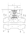
- FIG. 1 shows the cross section of a compound-eye imaging optical system respond
- FIG. 1 the image side surface (lens final surface closest to the imaging element) S4a of the single lens L2a of the second array lens LA2a in the first single-eye optical system IL1 and the second single-eye optical system IL2 adjacent thereto. Attention is paid to the image side surface S4b of the single lens L2b of the second array lens LA2b.
- the “maximum surface angle ⁇ 2” is defined by the tangent line L1 on the curved surface of the image side surface S4b of the single-lens lens LA2b, which is the final lens, and the line L2 perpendicular to the optical axis OX2 in the cross section in the optical axis direction of FIG. The angle is negative when the tangent line L1 is in the clockwise direction around the intersection with respect to the line L2, and positive when it is in the counterclockwise direction.
- the light-shielding aperture SH should be provided.
- the upper limit of conditional expression (1) represents the line segment N1 with the dimensions of each part as variables. Therefore, it can be said that the aperture size (R / 2) of the light-shielding stop SH is preferably less than the upper limit of the conditional expression (1).
- the light-shielding stop SH when the light-shielding stop SH is provided, the light-shielding stop SH should be provided so that the opening edge is disposed on the optical axis OX1 side from the line segment N2.
- the upper limit of conditional expression (2) represents the line segment N2 as a variable of each part dimension. Therefore, it can be said that the aperture size (R / 2) of the light-shielding stop SH is preferably less than the upper limit of the conditional expression (2).
- d1 d2.
- the aperture size differs by changing the position of the light-shielding stop SH in the optical axis direction.
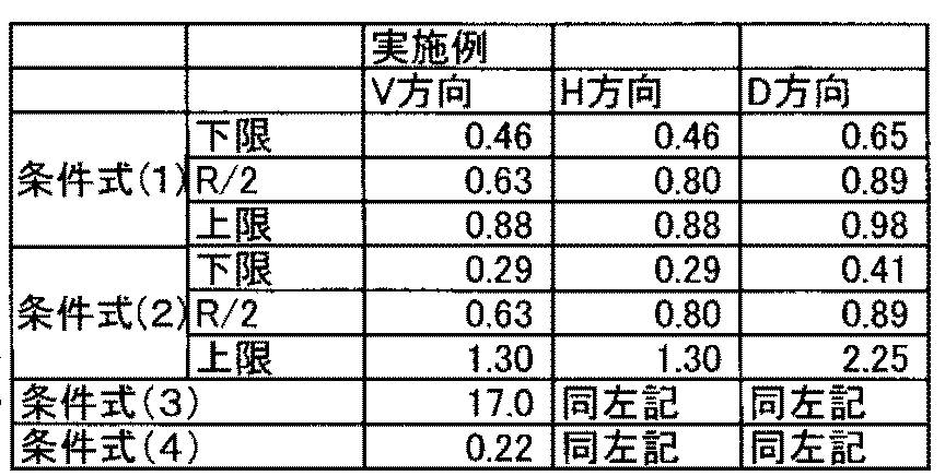
- conditional expressions (1) and (2) when the values of conditional expressions (1) and (2) are below the upper limit, the strongest direct incident crosstalk can be shielded.
- the values of conditional expressions (1) and (2) exceed the lower limit, the opening dimension of the light-shielding diaphragm does not become too small, and the effective luminous flux can be prevented from being scattered, and the effective imaging area is widened. I can do it. As a result, a good image with less noise can be obtained.
- FIG. 3 is a cross-sectional view in the optical axis direction of a single-eye lens closest to the image according to the present embodiment. It is a figure which shows typically the compound-eye imaging device by this embodiment. It is an expanded sectional view of compound eye imaging optical system LH by this embodiment. It is the figure which cut
- 2 is a cross-sectional view of a single-lens lens of Example 1.
- FIG. FIG. 4 is an aberration diagram of Example 1 (spherical aberration (a), astigmatism (b), distortion (c)).
- the compound-eye imaging system is an optical system in which a plurality of lens systems are arranged in an array with respect to one imaging device, and each lens system captures the same field of view, and each field has a different field of view.
- it is divided into a field division type that performs imaging of the above.
- a compound-eye imaging system according to a field division type that performs a plurality of images with different fields of view in order to connect a plurality of images with different fields of view and output a single composite image will be described.
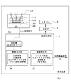
- FIG. 3 schematically shows a compound eye imaging apparatus according to the present embodiment.
- the compound-eye imaging device DU includes an imaging unit LU, an image processing unit 1, a calculation unit 2, a memory 3, and the like.
- the imaging unit LU includes one imaging element SR and a compound-eye imaging optical system LH that performs a plurality of imaging with different fields of view on the imaging element SR.
- the image sensor SR for example, a solid-state image sensor such as a CCD image sensor or a CMOS image sensor having a plurality of pixels is used.
- the compound-eye imaging optical system LH is provided on the light-receiving surface SS that is the photoelectric conversion unit of the imaging element SR so that an optical image of the subject is formed, the optical image formed by the compound-eye imaging optical system LH is Then, it is converted into an electrical signal by the image sensor SR.
- FIG. 4 is an enlarged cross-sectional view of the compound-eye imaging optical system LH according to the present embodiment.
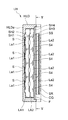
- FIG. 5 is a view of the configuration of FIG. 4 taken along the line VV and viewed in the direction of the arrow.
- the compound-eye imaging optical system LH includes a first array lens LA1 and a second array lens LA2 in order from the object side, and is held by a lens frame HLD.
- An object side wall HLPa is formed on the object side of the lens frame HLD, and a plurality of aperture stops S are formed therein.
- Each array lens is formed by integrally forming a plurality of individual lenses La1 and La2 corresponding to the aperture stop S, and the number of individual lenses is the number of object images (on the imaging surface SS of the image sensor SR ( It is made equal to the number of single-eye images (here, 4 ⁇ 4). That is, the light beams that have passed through the single-eye lenses La1 and La2 stacked in the optical axis direction form one image on the imaging surface SS.
- the image side surface S4 of the single lens La2 of the second array lens LA2 has a convex shape at the periphery.
- a first light-shielding stop SH1 is formed between the object side wall HLPa of the lens frame HLD and the first array lens LA1, and a second light-shielding stop SH2 is formed between the first array lens LA1 and the second array lens LA2.
- a third light-shielding stop SH3 is formed adjacent to the image side of the second array lens LA2.
- the first light-shielding stop SH1, the second light-shielding stop SH2, and the third light-shielding stop SH3 are made of a SUS plate material having a thickness of 20 ⁇ m to 100 ⁇ m.
- an IR cut filter F and a cover glass CG covering the imaging surface SR of the imaging element SR are arranged in this order from the object side.
- a light shielding film is formed in close contact with the object side surface of the IR cut filter F as an optical member, and this is the fourth light shielding stop SH4. Any one of the third light-shielding diaphragm SH3 and the fourth light-shielding diaphragm SH4 may be omitted.
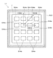
- Each of the light-shielding stops SH1 to SH4 has an opening (see FIG. 5) corresponding to each individual lens.
- a light shielding film may be formed in close contact with the periphery of the image side surface S4 of the single lens La2 or on the cover glass CG to function as a light shielding film.
- the light-shielding stop SH4 has a rectangular opening SH4a.
- the horizontal direction in the compound-eye imaging device at the time of imaging is defined as H direction
- the vertical direction is defined as V direction
- the diagonal direction is defined as D direction.
- the opening SH4a has a dimension in the H direction larger than a dimension in the V direction.
- the distance between the optical axes of the single-lens lenses is formed to be equal in the H direction, the V direction, and the D direction.
- the opening SH4a may have an elliptical shape.
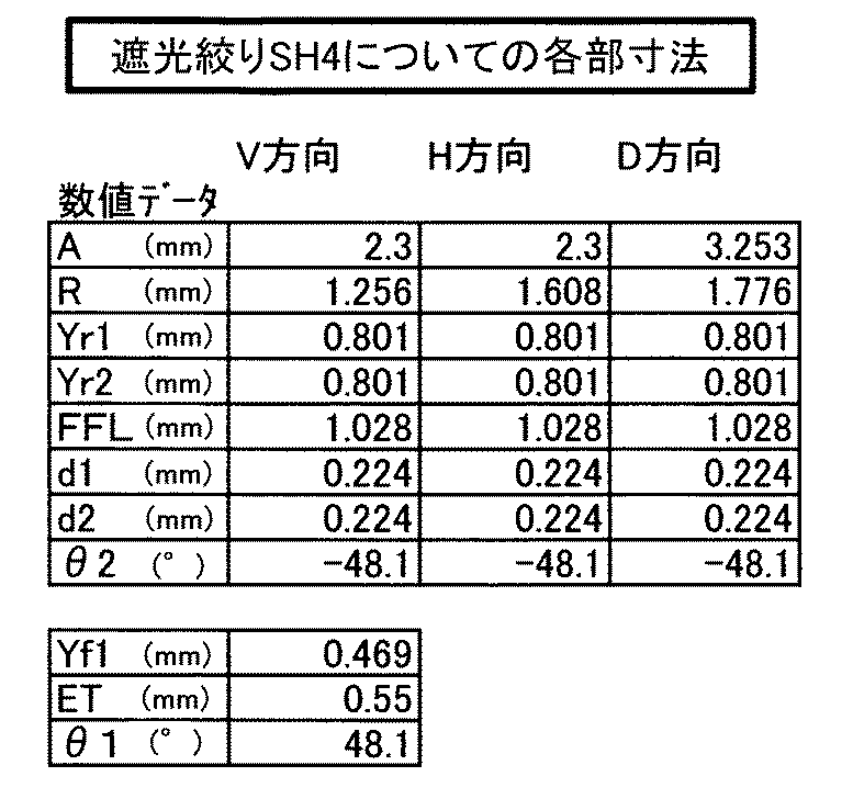
- the fourth light-shielding stop SH4 is formed so as to satisfy the following conditional expressions simultaneously (see FIG. 1). ).
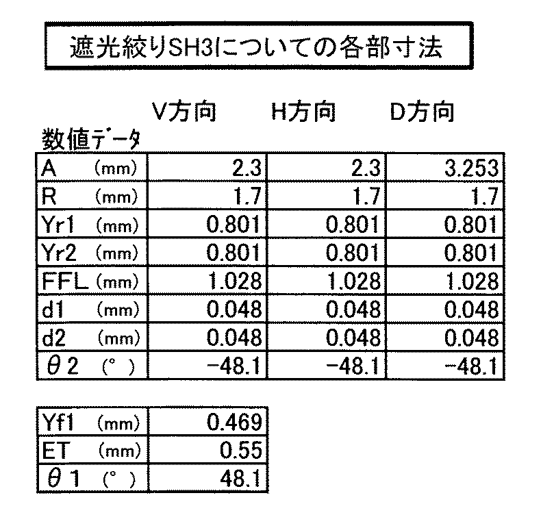
- the third light-shielding stop SH3 is formed so as to satisfy the following conditional expressions in the V direction and the H direction.
- the third light-shielding stop SH3 may satisfy the formula (1) or (2), and the fourth light-shielding stop SH4 may satisfy the formula (2) or (1).
- a / 9 ⁇ (R / 2) ⁇ A- (Yr2-d2 / tan ⁇ 2) (2)
- Yr1 Effective radius (mm) of the final surface of the first lens
- Yr2 Effective radius (mm) of the final surface of the second lens
- R Opening length (mm) of the light-shielding stop in the direction orthogonal to the optical axis of the single-eye optical system
- FFL distance in the optical axis direction from the lens surface edge of the first lens final surface to the central beam imaging point (mm)
- d2 Distance in the optical axis direction from
- the single-lens lenses have the same design specifications.
- the single-lens lenses in one array lens may be designed for at least three different wavelength distributions and have different optical characteristics. good.
- the single lens in one array lens may be combined with a plurality of color filters having transmittances corresponding to a plurality of different wavelength distributions.
- the image processing unit 1 includes an image composition unit 1a and an image correction unit 1b.
- One single-eye synthesized image ML can be output.
- the image correction unit 1b performs inversion processing, distortion processing, shading processing, stitching processing, and the like. Further, distortion correction is performed as necessary.
- the single-eye composite image ML is compressed by the calculation unit 2 and stored in the memory 3.
- each final lens closest to the imaging element in the single-eye optical system satisfies the following conditional expression.
- ⁇ 1- ⁇ ⁇ 0 (3)
- t réellen ⁇ (Yr1-Yf1) / ET
- Yf1 Effective radius (mm) of the object side surface of the final lens
- Yr1 Effective radius (mm) of the image side surface of the final lens
- ET Edge thickness of the final lens (mm)
- ⁇ 1 Maximum surface angle (°) at an effective diameter of 70% or more of the image side surface of the final lens
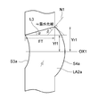
- FIG. 2 is a cross-sectional view of the final lens of the single-eye optical system according to the present embodiment, and an image sensor is present on the right side of FIG.
- the line segment connecting the effective diameter position of the object side surface S3a of the single lens LA2a and the effective diameter position of the image side surface S4a is L3
- the outermost ray passing through the single lens LA2a is the line segment L3. It passes through the optical axis OX1 side.
- the light-shielding diaphragm is disposed at a position that satisfies the following conditional expression.
- d1 ⁇ dn ⁇ 6/7 (4)
- dn a line segment N1 from the lens surface edge of the first lens final surface to the position A / 2 from the optical axis on the image pickup surface of the image sensor, and a normal N2 at the lens surface edge of the second lens final surface Is the distance in the optical axis direction from the intersection point to the lens surface edge of the first lens final surface, and is expressed by the following equation (Equation 1).
- the effective light beam emitted from the image side surface S4a as the final lens surface is less likely to be vignetted by the light shielding stop SH. Therefore, the aperture size of the light shielding stop SH is reduced. Thus, crosstalk can be shielded more efficiently.
- high image height light rays with an emission angle can be regulated at a low position, it is advantageous for widening the angle and expanding the effective imaging area.
- the aperture stop is disposed closer to the object side than the object side surface of the final lens closest to the image sensor.
- the exit pupil position can be on the object side, and the light exit angle from the final surface can be reduced. Therefore, the degree of freedom of the aperture size and position of the light-shielding diaphragm is increased, and the crosstalk can be shielded efficiently.
- the light-shielding diaphragm is preferably short or oval.
- the degree of freedom of lens arrangement in the short side direction can be improved, and the optical axis orthogonal dimension of the compound eye optical system can be reduced.
- the light-shielding diaphragm is separated from other optical members.
- other optical members for example, IR cut filter, cover glass, etc.
- the degree of freedom of the position is increased, and the light-shielding diaphragm is arranged at an optimum position where the outermost light rays are collected at the center. , Can effectively block crosstalk.
- the light-shielding diaphragm has a thickness of 20 ⁇ m or more and 100 ⁇ m or less.
- the thickness of the light-shielding diaphragm By setting the thickness of the light-shielding diaphragm to 20 ⁇ m or more, it is possible to prevent warpage of the whole light-shielding diaphragm and to suppress the occurrence of crosstalk due to the opening position shift.
- the thickness of the light-shielding stop is set to 100 ⁇ m or less, the amount of displacement when the whole light-shielding stop or individual apertures are shifted with respect to an angled ray can be reduced. This is advantageous for expanding the area.
- the light-shielding diaphragm is in close contact with the lens final surface.
- the thickness of the light-shielding stop itself can be reduced, and the ghost of reflection at the end face of the opening can be suppressed. Less likely to occur.
- an IR cut filter is provided between the array lens and the image sensor, and the light-shielding diaphragm is in close contact with the surface of the IR cut filter.
- a cover glass is provided between the array lens and the imaging device, and the light-shielding diaphragm is in close contact with the surface of the cover glass.
- Table 1 shows the dimensions of each part related to the third light-shielding stop SH3 of this example.
- Table 3 shows the dimensions of each part related to the fourth light-shielding stop SH4 of this example.
- the two lenses arranged in the optical axis direction (referred to as single-eye optical system) in the compound-eye imaging optical system are common, so the specifications will be described.
- FL Focal length of the entire single-eye optical system (mm)
- Fno F number
- ⁇ Half angle of view (°)
- Ymax Diagonal length of the imaging surface of the solid-state imaging device
- TL Distance on the optical axis from the lens surface closest to the object side to the image-side focal point of the entire single-eye optical system (however, “image-side focal point” refers to single-eye light This is the image point when a parallel ray parallel to the optical axis is incident on the academic system.
- BF Back focus (mm)
- r radius of curvature (mm)
- d Distance between shaft upper surfaces (mm)
- nd refractive index of lens material with respect to d-line
- ⁇ d Abbe number of lens material
- S is a surface number, and a surface described as SPS after the surface number is a surface having an aspherical shape.
- the aspherical shape has an apex at the surface as an origin and X in the optical axis direction.
- the axis is taken and the height in the direction perpendicular to the optical axis is h, and is expressed by the following “Equation 2”.
- Example 1 Table 5 shows lens data of Example 1. In the following (including the lens data in the table), a power of 10 (for example, 2.5 ⁇ 10 ⁇ 02 ) is expressed using E (for example, 2.5E-02).
- E for example, 2.5E-02.
- 6 is a cross-sectional view of the single-lens lens of Example 1.
- La1 is a first lens having a positive refractive power
- La2 is a second lens.
- S denotes an aperture stop
- I denotes an imaging surface
- F denotes an optical low-pass filter or IR cut filter
- CG denotes a parallel plate assuming a sealing glass of a solid-state imaging device.
- Example 7 is an aberration diagram of Example 1 (spherical aberration (a), astigmatism (b), distortion (c)).
- the solid line represents the amount of spherical aberration with respect to the d-line and the dotted line, respectively
- the solid line S represents the sagittal surface and the dotted line M represents the meridional surface.
Landscapes
- Physics & Mathematics (AREA)
- General Physics & Mathematics (AREA)
- Optics & Photonics (AREA)
- Health & Medical Sciences (AREA)
- Toxicology (AREA)
- Lenses (AREA)
- Optical Elements Other Than Lenses (AREA)
- Lens Barrels (AREA)
- Blocking Light For Cameras (AREA)
Abstract
Description
前記複眼撮像光学系は、少なくとも2枚以上のアレイレンズからなり、各アレイレンズは複数の個眼レンズを一体に形成してなり、光軸方向に積層された複数の個眼レンズにより複数の個眼光学系が形成され、複数の個眼光学系により複数の物体像がそれぞれ形成されるようになっており、前記個眼光学系の数は前記撮像素子に取得される前記物体像の数と等しくなっており、
前記個眼光学系における最も前記撮像素子に近いレンズ最終面は周辺部が凸の形状を有し、
前記レンズ最終面のレンズ面縁よりも像側に少なくとも一枚の遮光絞りを備え、
前記遮光絞りは、各個眼レンズの各々に対応する開口部を持ち、前記レンズ最終面のうち隣接する2つのレンズ最終面の一方を第1レンズ最終面とし、他方を第2レンズ最終面とすると、前記遮光絞りが1枚の場合には、以下の条件式(1)、(2)を同時に満足し、前記遮光絞りが2枚以上の場合には、いずれかの前記遮光絞りが、以下の条件式(1)、(2)を同時に満足するか、又はいずれかの前記遮光絞りが条件式(1)を満足し、且つ残りの前記遮光絞りが条件式(2)を満足することを特徴とする。
A/9<(R/2)<(A/2-Yr1)×d1/FFL+Yr1 (1)
A/9<(R/2)< A-(Yr2-d2/tanθ2) (2)
但し、
A:前記第1レンズ最終面と前記第2レンズ最終面の光軸間距離(mm)
Yr1:前記第1レンズ最終面の有効半径(mm)
Yr2:前記第2レンズ最終面の有効半径(mm)
R:前記個眼光学系の光軸直交方向における前記遮光絞りの開口長(mm)
FFL:前記第1レンズ最終面のレンズ面縁から中心光束結像点までの光軸方向の距離(mm)
d1:前記第1レンズ最終面のレンズ面縁から遮光絞りまでの光軸方向の距離(mm)
d2:前記第2レンズ最終面のレンズ面縁から遮光絞りまでの光軸方向の距離(mm)
θ2:前記第2レンズ最終面の有効径7割以上の最大面角度(°)
A/9<(R/2)<(A/2-Yr1)×d1/FFL+Yr1 (1)
A/9<(R/2)< A-(Yr2-d2/tanθ2) (2)
但し、
A:第1レンズ最終面と第2レンズ最終面の光軸間距離(mm)
Yr1:第1レンズ最終面の有効半径(mm)
Yr2:第2レンズ最終面の有効半径(mm)
R:個眼光学系の光軸直交方向における遮光絞りの開口長(mm)
FFL:第1レンズ最終面のレンズ面縁から中心光束結像点までの光軸方向の距離(mm)d1:第1レンズ最終面のレンズ面縁から遮光絞りまでの光軸方向の距離(mm)
d2:第2レンズ最終面のレンズ面縁から遮光絞りまでの光軸方向の距離(mm)
θ2:第2レンズ最終面の有効径7割以上における最大面角度(°)
θ1-α≧0 (3)
但し、
tаnα=(Yr1-Yf1)/ET
Yf1:前記最終レンズの物体側面の有効半径(mm)
Yr1:前記最終レンズの像側面の有効半径(mm)
ET:前記最終レンズの縁厚(mm)
θ1:前記最終レンズの像側面の有効径7割以上における最大面角度(°)
β=θ1-α (3)
ここで、tаnα=(Yr1-Yf1)/ET,且つβ≧0の場合、物体側面S4aを通過した最外光線が光軸OX1側に屈折することになるから、条件式(3)を満足することで、レンズ最終面周辺部へ入射する画角外の光線を跳ね上げにくくなるため,遮光絞りの開口寸法や位置の自由度が増し、効率良くクロストークを遮光することができる。尚、最終レンズ形状が互いに等しければ、θ1=θ2となる。
d1<dn×6/7 (4)
但し、
dn:前記第1レンズ最終面のレンズ面縁から、前記撮像素子の撮像面上における光軸からA/2の位置まで線分N1と、前記第2レンズ最終面のレンズ面縁における法線N2との交点から第1レンズ最終面のレンズ面縁までの光軸方向の距離であり、以下の式(数1)で表される。


FL:個眼光学系全系の焦点距離(mm)
Fno:Fナンバー
ω:半画角(゜)
Ymax::固体撮像素子の撮像面対角線長
TL:個眼光学系全系の最も物体側のレンズ面から像側焦点までの光軸上の距離(但し、「像側焦点」とは、個眼光学系に光軸と平行な平行光線が入射した場合の像点をいう。)BF:バックフォーカス(mm)
r :曲率半径(mm)
d :軸上面間隔(mm)
nd:レンズ材料のd線に対する屈折率
νd:レンズ材料のアッベ数

Ai:i次の非球面係数
R :曲率半径
K :円錐定数
実施例1のレンズデータを表5に示す。なお、これ以降(表のレンズデータを含む)において、10のべき乗数(たとえば2.5×10-02)を、E(たとえば2.5E-02)を用いて表すものとする。図6は、実施例1の個眼レンズの断面図である。図中、La1は正の屈折力を有する第1レンズ、La2は第2レンズである。Sは開口絞り、Iは撮像面を示し、Fは光学的ローパスフィルタやIRカットフィルタ、CGは固体撮像素子のシールガラス等を想定した平行平板を示す。図7は実施例1の収差図(球面収差(a)、非点収差(b)、歪曲収差(c))である。ここで、球面収差図において、実線はd線、点線はg線に対する球面収差量をそれぞれ表し、非点収差図において、実線Sはサジタル面、点線Mはメリディオナル面を表す。
[実施例1 レンズデータ]
Reference Wave Length = 587.56 nm
SURF DATA
NUM. r d nd vd
OBJ INFINITY 400.0000
1 INFINITY 0.0500
STO INFINITY -0.0800
3SPS 0.6246 0.5700 1.54470 56.15
4SPS 1.1431 0.2990
5SPS -4.9482 0.6310 1.54470 56.15
6SPS 1e+018 -0.1290
7 INFINITY 0.0300
8 INFINITY 0.2396
9 INFINITY 0.1750 1.52310 54.49
10 INFINITY 0.1000
11 INFINITY 0.4000 1.52310 62.19
12 INFINITY 0.0198
IMG INFINITY 0.0000
ASPHERICAL SURFACE
3:K=-2.22760e+000,A3=1.52470e-001,A4=1.81620e-001,A5=-7.31690e+000,A6=8.29560e+001,A7=0.00000e+000,A8=-1.49450e+003,A9=0.00000e+000,A10=1.79280e+004,A11=0.00000e+000,A12=-1.11850e+005,A13=0.00000e+000,A14=2.78480e+005,A15=0.00000e+000,A16=0.00000e+000,A17=0.00000e+000,A18=0.00000e+000,A19=0.00000e+000,A20=0.00000e+000
4:K=2.21570e+000,A3=5.06690e-001,A4=-3.56260e+000,A5=0.00000e+000,A6=1.10340e+002,A7=0.00000e+000,A8=-2.46130e+003,A9=0.00000e+000,A10=3.62720e+004,A11=0.00000e+000,A12=-3.15550e+005,A13=0.00000e+000,A14=1.48410e+006,A15=0.00000e+000,A16=-2.86020e+006,A17=0.00000e+000,A18=0.00000e+000,A19=0.00000e+000,A20=0.00000e+000
5:K=0.00000e+000,A3=-1.07640e-001,A4=-6.12280e-001,A5=0.00000e+000,A6=1.00490e+000,A7=0.00000e+000,A8=-1.05310e+002,A9=0.00000e+000,A10=1.20730e+003,A11=0.00000e+000,A12=-6.11470e+003,A13=0.00000e+000,A14=9.57870e+003,A15=0.00000e+000,A16=8.80570e+003,A17=0.00000e+000,A18=0.00000e+000,A19=0.00000e+000,A20=0.00000e+000
6:K=0.00000e+000,A3=0.00000e+000,A4=-1.48800e-001,A5=0.00000e+000,A6=-1.08300e+000,A7=0.00000e+000,A8=4.46510e+000,A9=0.00000e+000,A10=-1.59220e+001,A11=0.00000e+000,A12=3.49940e+001,A13=0.00000e+000,A14=-4.22730e+001,A15=0.00000e+000,A16=2.07620e+001,A17=0.00000e+000,A18=0.00000e+000,A19=0.00000e+000,A20=0.00000e+000
FL 2.031
Fno 3.096
ω 27.47
Ymax 1.0945
BF 0.835
TTL 2.335
Elem Surfs Focal Length(mm)
1 3-4 1.82
2 5-6 -9.08
1a 画像合成部
1b 画像補正部
2 演算部
3 メモリー
DU 複眼撮像装置
F カバーガラス
LA1 第1レンズアレイ
LA2 第2レンズアレイ
LH 複眼撮像系
La1 第1個眼アレイ
La2 第2個眼アレイ
LU 撮像ユニット
SR 撮像素子
SS 撮像面
SH1~SH4 遮光絞り
Claims (10)
- 複数の物体像を形成する複眼撮像光学系と、物体像を取得する撮像素子とを有する複眼撮像装置において、
前記複眼撮像光学系は、少なくとも2枚以上のアレイレンズからなり、各アレイレンズは複数の個眼レンズを一体に形成してなり、光軸方向に積層された複数の個眼レンズにより複数の個眼光学系が形成され、複数の個眼光学系により複数の物体像がそれぞれ形成されるようになっており、前記個眼光学系の数は前記撮像素子に取得される前記物体像の数と等しくなっており、
前記個眼光学系における最も前記撮像素子に近いレンズ最終面は周辺部が凸の形状を有し、
前記レンズ最終面のレンズ面縁よりも像側に少なくとも一枚の遮光絞りを備え、
前記遮光絞りは、各個眼レンズの各々に対応する開口部を持ち、前記レンズ最終面のうち隣接する2つのレンズ最終面の一方を第1レンズ最終面とし、他方を第2レンズ最終面とすると、前記遮光絞りが1枚の場合には、以下の条件式(1)、(2)を同時に満足し、前記遮光絞りが2枚以上の場合には、いずれかの前記遮光絞りが、以下の条件式(1)、(2)を同時に満足するか、又はいずれかの前記遮光絞りが条件式(1)を満足し、且つ残りの前記遮光絞りが条件式(2)を満足することを特徴とする複眼撮像装置。
A/9<(R/2)<(A/2-Yr1)×d1/FFL+Yr1 (1)
A/9<(R/2)< A-(Yr2-d2/tanθ2) (2)
但し、
A:前記第1レンズ最終面と前記第2レンズ最終面の光軸間距離(mm)
Yr1:前記第1レンズ最終面の有効半径(mm)
Yr2:前記第2レンズ最終面の有効半径(mm)
R:前記個眼光学系の光軸直交方向における前記遮光絞りの開口長(mm)
FFL:前記第1レンズ最終面のレンズ面縁から中心光束結像点までの光軸方向の距離(mm)
d1:前記第1レンズ最終面のレンズ面縁から遮光絞りまでの光軸方向の距離(mm)
d2:前記第2レンズ最終面のレンズ面縁から遮光絞りまでの光軸方向の距離(mm)
θ2:前記第2レンズ最終面の有効径7割以上における最大面角度(°) - 前記個眼光学系における最も前記撮像素子に近い最終レンズ各々が、以下の条件式を満足することを特徴とする、請求項1に記載の複眼撮像装置。
θ1-α≧0 (3)
但し、
tаnα=(Yr1-Yf1)/ET
Yf1:前記最終レンズの物体側面の有効半径(mm)
Yr1:前記最終レンズの像側面の有効半径(mm)
ET:前記最終レンズの縁厚(mm)
θ1:前記最終レンズの像側面の有効径7割以上における最大面角度(°) - 前記遮光絞りは下記条件式を満足する位置に配置されることを特徴とする、請求項1又は2に記載の複眼撮像装置。
d1<dn×6/7 (4)
但し、
dn:前記第1レンズ最終面のレンズ面縁から、前記撮像素子の撮像面上における光軸からA/2の位置まで線分N1と、前記第2レンズ最終面のレンズ面縁における法線N2との交点から第1レンズ最終面のレンズ面縁までの光軸方向の距離であり、以下の式で表される。

- 開口絞りは、最も前記撮像素子に近い最終レンズの物体側面よりも物体側に配置されることを特徴とする請求項1~3のいずれかに記載の複眼撮像装置。
- 前記遮光絞りは短形または楕円形であることを特徴とする請求項1~4のいずれかに記載の複眼撮像装置。
- 前記遮光絞りは他の光学部材と分離されていることを特徴とする請求項1~5のいずれかに記載の複眼撮像装置。
- 前記遮光絞りは厚みが20μm以上、100μm以下であることを特徴とする請求項6に記載の複眼撮像装置。
- 前記遮光絞りは前記レンズ最終面と密着していることを特徴とする請求項1~5のいずれかに記載の複眼撮像装置。
- 前記アレイレンズと前記撮像素子との間にIRカットフィルタを有し、前記遮光絞りは前記IRカットフィルタの表面に密着していることを特徴とする請求項1~8のいずれかに記載の複眼撮像装置。
- 前記アレイレンズと前記撮像素子との間にカバーガラスを有し、前記遮光絞りは前記カバーガラスの表面に密着していることを特徴とする請求項1~9のいずれかに記載の複眼撮像装置。
Priority Applications (2)
| Application Number | Priority Date | Filing Date | Title |
|---|---|---|---|
| CN201480032860.1A CN105393154B (zh) | 2013-06-10 | 2014-05-14 | 复眼摄像装置 |
| JP2015522661A JPWO2014199765A1 (ja) | 2013-06-10 | 2014-05-14 | 複眼撮像装置 |
Applications Claiming Priority (2)
| Application Number | Priority Date | Filing Date | Title |
|---|---|---|---|
| JP2013-121666 | 2013-06-10 | ||
| JP2013121666 | 2013-06-10 |
Publications (1)
| Publication Number | Publication Date |
|---|---|
| WO2014199765A1 true WO2014199765A1 (ja) | 2014-12-18 |
Family
ID=52022066
Family Applications (1)
| Application Number | Title | Priority Date | Filing Date |
|---|---|---|---|
| PCT/JP2014/062789 Ceased WO2014199765A1 (ja) | 2013-06-10 | 2014-05-14 | 複眼撮像装置 |
Country Status (3)
| Country | Link |
|---|---|
| JP (1) | JPWO2014199765A1 (ja) |
| CN (1) | CN105393154B (ja) |
| WO (1) | WO2014199765A1 (ja) |
Cited By (4)
| Publication number | Priority date | Publication date | Assignee | Title |
|---|---|---|---|---|
| JP2016184082A (ja) * | 2015-03-26 | 2016-10-20 | 日立マクセル株式会社 | レンズユニットおよびカメラモジュール |
| JP2017097314A (ja) * | 2015-11-17 | 2017-06-01 | エーエーシー テクノロジーズ ピーティーイー リミテッド | レンズモジュール |
| JP2018514806A (ja) * | 2015-04-13 | 2018-06-07 | イー.ブイ.エス.ソシエタ ア レスポンサビリタ リミタータ センプリフィカータ | 両眼視野を改善するための設備 |
| CN112748540A (zh) * | 2021-01-07 | 2021-05-04 | 江西欧迈斯微电子有限公司 | 光学成像系统、摄像模组及终端设备 |
Families Citing this family (2)
| Publication number | Priority date | Publication date | Assignee | Title |
|---|---|---|---|---|
| CN114200691A (zh) * | 2021-12-02 | 2022-03-18 | 安徽省东超科技有限公司 | 微透镜阵列成像元件和成像装置 |
| CN114545607B (zh) * | 2022-01-26 | 2023-04-07 | 北京理工大学 | 一种微型超近距离大景深复眼成像系统 |
Citations (5)
| Publication number | Priority date | Publication date | Assignee | Title |
|---|---|---|---|---|
| JP2002170944A (ja) * | 2000-11-30 | 2002-06-14 | Canon Inc | 固体撮像装置 |
| JP2005176117A (ja) * | 2003-12-12 | 2005-06-30 | Canon Inc | 撮像装置 |
| JP2007180653A (ja) * | 2005-12-27 | 2007-07-12 | Funai Electric Co Ltd | 複眼撮像装置 |
| JP2007329714A (ja) * | 2006-06-08 | 2007-12-20 | Funai Electric Co Ltd | 複眼撮像装置 |
| JP2008083398A (ja) * | 2006-09-27 | 2008-04-10 | Olympus Corp | 複眼光学系及びそれを用いた光学装置 |
Family Cites Families (1)
| Publication number | Priority date | Publication date | Assignee | Title |
|---|---|---|---|---|
| US6995800B2 (en) * | 2000-01-27 | 2006-02-07 | Canon Kabushiki Kaisha | Image pickup apparatus utilizing a plurality of converging lenses |
-
2014
- 2014-05-14 CN CN201480032860.1A patent/CN105393154B/zh not_active Expired - Fee Related
- 2014-05-14 WO PCT/JP2014/062789 patent/WO2014199765A1/ja not_active Ceased
- 2014-05-14 JP JP2015522661A patent/JPWO2014199765A1/ja active Pending
Patent Citations (5)
| Publication number | Priority date | Publication date | Assignee | Title |
|---|---|---|---|---|
| JP2002170944A (ja) * | 2000-11-30 | 2002-06-14 | Canon Inc | 固体撮像装置 |
| JP2005176117A (ja) * | 2003-12-12 | 2005-06-30 | Canon Inc | 撮像装置 |
| JP2007180653A (ja) * | 2005-12-27 | 2007-07-12 | Funai Electric Co Ltd | 複眼撮像装置 |
| JP2007329714A (ja) * | 2006-06-08 | 2007-12-20 | Funai Electric Co Ltd | 複眼撮像装置 |
| JP2008083398A (ja) * | 2006-09-27 | 2008-04-10 | Olympus Corp | 複眼光学系及びそれを用いた光学装置 |
Cited By (4)
| Publication number | Priority date | Publication date | Assignee | Title |
|---|---|---|---|---|
| JP2016184082A (ja) * | 2015-03-26 | 2016-10-20 | 日立マクセル株式会社 | レンズユニットおよびカメラモジュール |
| JP2018514806A (ja) * | 2015-04-13 | 2018-06-07 | イー.ブイ.エス.ソシエタ ア レスポンサビリタ リミタータ センプリフィカータ | 両眼視野を改善するための設備 |
| JP2017097314A (ja) * | 2015-11-17 | 2017-06-01 | エーエーシー テクノロジーズ ピーティーイー リミテッド | レンズモジュール |
| CN112748540A (zh) * | 2021-01-07 | 2021-05-04 | 江西欧迈斯微电子有限公司 | 光学成像系统、摄像模组及终端设备 |
Also Published As
| Publication number | Publication date |
|---|---|
| CN105393154A (zh) | 2016-03-09 |
| JPWO2014199765A1 (ja) | 2017-02-23 |
| CN105393154B (zh) | 2018-06-12 |
Similar Documents
| Publication | Publication Date | Title |
|---|---|---|
| JP4633379B2 (ja) | 魚眼レンズおよびこれを用いた撮像装置 | |
| JP5463265B2 (ja) | 広角レンズ | |
| JP4416391B2 (ja) | 広角レンズ、カメラおよび投写型表示装置 | |
| US10007085B2 (en) | Optical image capturing system | |
| US9581791B1 (en) | Optical image capturing system | |
| JP2024055909A (ja) | レンズ装置およびそれを有する撮像装置 | |
| JP3564107B2 (ja) | コンパクトな撮影レンズ | |
| JP6383214B2 (ja) | 結像光学系及びそれを備えた光学装置 | |
| US9880396B2 (en) | Optical image capturing system | |
| JP2009128654A (ja) | 魚眼系撮像レンズ | |
| US20170052345A1 (en) | Optical image capturing system | |
| JP2006292988A (ja) | 広角レンズ、及び、撮像装置 | |
| CN112649943B (zh) | 光学成像系统、模组和电子设备 | |
| JP2004102162A (ja) | 超広角レンズ | |
| WO2014199765A1 (ja) | 複眼撮像装置 | |
| JP2007212877A (ja) | 単焦点撮像レンズ及びそれを備えた撮像装置 | |
| WO2010071077A1 (ja) | 撮像レンズ | |
| JP5718020B2 (ja) | ズームレンズ及び撮像装置 | |
| JP4208667B2 (ja) | ズームレンズおよび撮像装置 | |
| JP7353876B2 (ja) | 光学系およびそれを有する撮像装置 | |
| JP6517563B2 (ja) | インナーフォーカス式レンズ | |
| JP2015036794A (ja) | 複眼撮像光学系及び複眼撮像装置 | |
| WO2014181643A1 (ja) | 複眼撮像系及び撮像装置 | |
| CN115079373B (zh) | 光学成像系统、取像模组及电子装置 | |
| WO2011077988A1 (ja) | 撮像光学系 |
Legal Events
| Date | Code | Title | Description |
|---|---|---|---|
| WWE | Wipo information: entry into national phase |
Ref document number: 201480032860.1 Country of ref document: CN |
|
| 121 | Ep: the epo has been informed by wipo that ep was designated in this application |
Ref document number: 14811601 Country of ref document: EP Kind code of ref document: A1 |
|
| ENP | Entry into the national phase |
Ref document number: 2015522661 Country of ref document: JP Kind code of ref document: A |
|
| NENP | Non-entry into the national phase |
Ref country code: DE |
|
| 122 | Ep: pct application non-entry in european phase |
Ref document number: 14811601 Country of ref document: EP Kind code of ref document: A1 |