WO2014199730A1 - プレス成形方法 - Google Patents
プレス成形方法 Download PDFInfo
- Publication number
- WO2014199730A1 WO2014199730A1 PCT/JP2014/061581 JP2014061581W WO2014199730A1 WO 2014199730 A1 WO2014199730 A1 WO 2014199730A1 JP 2014061581 W JP2014061581 W JP 2014061581W WO 2014199730 A1 WO2014199730 A1 WO 2014199730A1
- Authority
- WO
- WIPO (PCT)
- Prior art keywords
- metal plate
- pad
- punch
- blank holder
- die
- Prior art date
- Legal status (The legal status is an assumption and is not a legal conclusion. Google has not performed a legal analysis and makes no representation as to the accuracy of the status listed.)
- Ceased
Links
Images









Classifications
-
- B—PERFORMING OPERATIONS; TRANSPORTING
- B21—MECHANICAL METAL-WORKING WITHOUT ESSENTIALLY REMOVING MATERIAL; PUNCHING METAL
- B21D—WORKING OR PROCESSING OF SHEET METAL OR METAL TUBES, RODS OR PROFILES WITHOUT ESSENTIALLY REMOVING MATERIAL; PUNCHING METAL
- B21D22/00—Shaping without cutting, by stamping, spinning, or deep-drawing
- B21D22/20—Deep-drawing
- B21D22/26—Deep-drawing for making peculiarly, e.g. irregularly, shaped articles
-
- B—PERFORMING OPERATIONS; TRANSPORTING
- B21—MECHANICAL METAL-WORKING WITHOUT ESSENTIALLY REMOVING MATERIAL; PUNCHING METAL
- B21D—WORKING OR PROCESSING OF SHEET METAL OR METAL TUBES, RODS OR PROFILES WITHOUT ESSENTIALLY REMOVING MATERIAL; PUNCHING METAL
- B21D24/00—Special deep-drawing arrangements in, or in connection with, presses
- B21D24/04—Blank holders; Mounting means therefor
Definitions
- the present invention relates to a press molding method for molding a part having an L-shaped part or a T-shaped part in plan view.
- parts having an L-shaped part or a T-shaped part in a plan view such as a front pillar reinforcement and a center pillar reinforcement, which are car body frame parts of an automobile, are pressed from a metal plate (press In the case of manufacturing by forming), a drawing method is usually adopted.
- the drawing method is usually performed using a die (of a press), a die (of a punch), a die (die), and a blank holder (blade holder). This is a method in which the metal plate is drawn by reducing the distance between the punch and the die while holding the entire periphery of the metal plate with the die and the blank holder.
- the technologies proposed so far include a plurality of press forming processes in which a die is replaced after bending to form an L-shaped part, and further bending is performed.
- a method of forming a final product shape through the above has been proposed (see Patent Document 1).
- a press molding method has been proposed in which a skeleton member having an L-shaped portion is press-molded using a mold unit including a die mold, a pad, and a bending die (see Patent Document 2). .
- Patent Document 1 increases the number of molding steps, which increases the cost.
- Patent Document 2 there is no problem when the flanges of the components are substantially on the same plane, but the flange shape is three-dimensional in accordance with the curved surface shape of the vehicle body such as a center pillar reinforcement. In the case where it is bent, the occurrence of wrinkles is further generated in the flange at a place other than the L-shaped part (a place corresponding to the straight part in FIG. 1 of FIG. 1 or FIG. 2) than in the conventional drawing. Become prominent.
- An object of the present invention is to provide a press molding method capable of suppressing wrinkles and avoiding cracks without increasing the number of molding steps in a part having a letter-shaped part or a T-shaped part.
- the press molding method includes a punch having a molding surface, a die having a molding surface corresponding to the punch, a blank holder for sandwiching a metal plate between the die, and a punch.
- a press mold having a pad that cooperates to sandwich a part of the metal plate, the metal plate is attached to the top plate portion and the vertical plate formed around the top plate portion.
- a press forming method comprising: a wall portion; and a flange portion continuously formed on the vertical wall portion, wherein the metal plate is formed by pressing the metal plate into a part having an L-shaped portion in plan view.
- the process starts at a position of 0% to 50% with respect to a forming depth from a position where the punch in the forming process starts to contact the metal plate to a bottom dead center position.
- An average pressure for pressing the metal plate by the die and the blank holder in the plate clamping step is 0.7 MPa or more, and the punch and the pad in the pad pressing step are set.
- the average pressure for pressing the metal plate with the door is 3 MPa or more.
- a press molding method includes a punch having a molding surface, a die having a molding surface corresponding to the punch, a blank holder for sandwiching a metal plate between the die, and a punch.
- a press mold that cooperates to sandwich a part of the metal plate, the metal plate, the top plate portion, and a vertical wall portion formed around the top plate portion A flange part formed continuously on the vertical wall part, and press-molding the part having a T-shaped part in plan view, wherein the metal plate is the metal plate in the metal plate
- a forming step of pressing the punch against the metal plate held between the die and the blank holder and forming the metal plate by drawing and after the metal plate clamping step
- the pad pressing step starts at a position of 0% to 50% with respect to the forming depth from the position where the punch in the forming step starts to contact the metal plate to the bottom dead center position,
- An average pressure for pressing the metal plate by the die and the blank holder in the plate clamping step is 0.7 MPa or more, and the punch and the pad in the pad pressing step The average pressure for pressing a metal plate, characterized in that not less than 3 MPa.
- the present invention in press molding of a part having an L-shaped part or a T-shaped part in plan view, even if an ultra-high strength high tensile material with low ductility is used as a metal plate, the number of molding processes is not increased. Suppression of cracks and avoidance of cracks can be realized.
- FIG. 1 is an explanatory diagram for explaining a press molding method according to the first embodiment of the present invention.
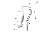
- FIG. 2 is a plan view of an L-shaped component which is a molding target of the press molding method according to the first embodiment of the present invention.
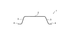
- FIG. 3 is an enlarged view of a cross section taken along the line AA of the L-shaped part shown in FIG.
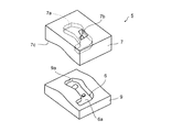
- FIG. 4 is an explanatory view illustrating a press molding die used in the press molding method according to the first embodiment of the present invention.
- FIG. 5 is an explanatory diagram for explaining a press molding die used in the press molding method according to the first embodiment of the present invention, and shows a state in which the press molding die is attached to the press molding apparatus. .
- FIG. 1 is an explanatory diagram for explaining a press molding method according to the first embodiment of the present invention.
- FIG. 2 is a plan view of an L-shaped component which is a molding target of the press molding method according to the first embodiment of the present invention.
- FIG. 3 is
- FIG. 6 is an explanatory diagram illustrating an example of a pad range in the pad pressing step of the press molding method according to the first embodiment of the present invention.
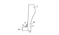
- FIG. 7 is an explanatory diagram illustrating an example of a pad range in a pad pressing step of the press molding method according to the first embodiment of the present invention.
- Drawing 8 is an explanatory view explaining an example of arrangement of a metal plate in a metal plate arrangement process of a press forming method concerning a 1st embodiment of the present invention.
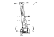
- FIG. 9 is a plan view of a center pillar shown as an example of a part having a T-shaped portion which is another molding target of the press molding method according to the second embodiment of the present invention.
- FIG. 10 is an enlarged view of a cross section taken along the line BB of the center pillar shown in FIG.
- FIG. 11 is an explanatory diagram for explaining an example of the arrangement of the metal plates in the metal plate arrangement step when the center pillar shown in FIG. 9 is press-formed.
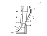
- FIG. 12 is a plan view of a front pillar which is a molding target of the press molding method according to the first embodiment of the present invention.
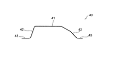
- 13 is an enlarged view of a cross section taken along the line CC of the front pillar shown in FIG.
- FIG. 14 is an explanatory view for explaining a lower die (lower die) of a press molding die used in the press molding method according to Embodiment 1 of the present invention.
- FIG. 15 is an explanatory diagram for explaining an upper die of a press molding die used in the press molding method according to Embodiment 1 of the present invention.
- FIG. 16 is an explanatory diagram of molding conditions of the press molding method according to the first embodiment of the present invention, and is an explanatory diagram for explaining the start position of the pad pressing process.
- FIG. 17 is an explanatory diagram of molding conditions of the press molding method according to the first embodiment of the present invention, and is an explanatory diagram for explaining the arrangement of the metal plates in the metal plate arranging step.
- FIG. 18 is an explanatory diagram of molding conditions of the press molding method according to the first embodiment of the present invention, and is an explanatory diagram for explaining a pad range in a pad pressing process.
- FIG. 19 is an explanatory diagram of molding conditions of the press molding method according to the second embodiment of the present invention, and is an explanatory diagram for explaining the arrangement of the metal plates in the metal plate arranging step.
- a press molding method according to the first embodiment of the present invention is performed by pressing an L-shaped part 1 shown in FIGS. 2 and 3 by using a press molding die 5 shown in FIGS.
- This is a molding method.
- the L-shaped part 1 and the press molding die 5 will be described.
- the L-shaped part 1 will be outlined below.
- the L-shaped component 1 includes an L-shaped top plate portion 2 having a long side and a short side in a plan view, and a vertical wall portion 3 formed around the top plate portion 2. , And a flange portion 4 continuously formed on the vertical wall portion 3, and has a hat-shape in cross section as shown in FIG.
- the vertical wall portion 3 and the flange portion 4 are not formed at both ends of the long side of the top plate portion 2 and the end portion of the short side (short side end portion 2a).
- the press mold 5 includes a punch 6 having a molding surface 6 a, a die 7 having a molding surface 7 a corresponding to the punch 6, and a metal plate 17 between the die 7 (see FIG. 5). ) And a pad 11 (see FIG. 5) that holds a part of the metal plate 17 in cooperation with the punch 6.
- the punch 6 and the blank holder 9 are attached to a bolster 13, and the die 7 and the pad 11 are attached to a slider 15.
- each configuration will be described in detail.
- the punch 6 has an L-shaped molding surface 6 a in plan view, and is disposed in an opening 9 a provided in the blank holder 9.
- the central portion of the die 7 is recessed in an L shape, and the inner surface of the recess is a molding surface 7 a corresponding to the punch 6.
- An opening 7b is provided at a position including an L-shaped bent portion on the molding surface 7a, and a pad 11 is disposed in the opening 7b (see FIGS. 5 and 6).
- the lower surface of the die 7 is a clamping surface 7 c that clamps the metal plate 17 with the blank holder 9.
- An opening 9a is provided at the center of the blank holder 9, and the punch 6 is disposed in the opening 9a.
- the blank holder 9 is supported by a cushion pin 19 so as to be movable up and down.
- the blank holder 9 is always supported so as to be positioned above the upper surface of the punch 6 and can be pushed down by the die 7 during press molding.
- the punch 6 protrudes relatively from the blank holder 9, and the upper part of the punch 6 is inserted into the die 7 (see FIG. 1C).
- the pad 11 is provided so as to be pressed toward the punch 6 by a gas cylinder 21 or the like, and in cooperation with the punch 6, the top plate 2 (see FIG. 2) in the metal plate 17. (See below).
- the shape of the pad 11 can press a portion corresponding to the bent portion 2 b (see FIG. 2) in the metal plate 17.
- the metal plate 17 is disposed so that the portion corresponding to the end of the L-shaped short side of the metal plate 17 does not cover the blank holder 9 (FIG. 1 ( a)), a metal plate clamping step (see FIG. 1B) for clamping the metal plate 17 placed on the blank holder 9 between the die 7 and the blank holder 9 by the metal plate placement step, and the die 7
- the punch 6 is pressed against the metal plate 17 held by the blank holder 9 to form the metal plate 17 by drawing, and the punch 6 and the pad 11 in the middle of the forming process after the metal plate holding step.
- a pad pressing step see FIG. 1C for pressing the position including the bent portion (elbow-shaped bend portion) 2b in the metal plate 17.
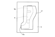
- the metal plate arranging step is a step of arranging the metal plate 17 so that the portion 17 a corresponding to the short side end 2 a of the metal plate 17 does not cover the blank holder 9.
- the load on the metal plate 17 at the portion is large, and the portion corresponding to the shoulder portion of the punch 6 in the metal plate 17 is formed. Cracks occur or wrinkles occur in the flange 4 near the component corner. Therefore, the metal plate 17 is arranged as described above to avoid the occurrence of cracks and wrinkles.
- the metal plate clamping step is a step of clamping the metal plate 17 arranged on the blank holder 9 by the metal plate arranging step between the die 7 and the blank holder 9.
- the reason why the metal plate 17 is sandwiched between the die 7 and the blank holder 9 is to suppress generation of wrinkles at the flange.
- the punch 7 is pushed in when not sandwiched between the die 7 and the blank holder 9, a freely movable portion of the metal plate 17 flows around the part shape changing portion, and wrinkles are likely to occur.
- the metal plate 17 can be easily deformed, so that large wrinkles are generated.
- the average pressure (blank holder pressure) for holding the metal plate 17 between the die 7 and the blank holder 9 is preferably 0.7 MPa or more.
- the forming step is a step of pressing the punch 6 against the metal plate 17 held between the die 7 and the blank holder 9 to form the metal plate 17 by drawing.
- the pad pressing step is a step of pressing a position including a portion corresponding to the bent portion 2b in the metal plate 17 by the punch 6 and the pad 11 during the molding process after the metal plate clamping step. In this way, pressing the metal plate 17 with the punch 6 and the pad 11 is effective in suppressing the generation of wrinkles in the bent portion 2b (see FIG. 7). If the range (pad range) in which the metal plate 17 is pressed by the punch 6 and the pad 11 is at least the bent portion 2b (see FIG. 2), it is possible to suppress the place where the generation of wrinkles becomes a problem. Further, the top plate 2 may be pressed in a wider range.
- the pad pressing step is 0 with respect to the forming depth from the position (see FIG. 1B) where the punch 6 in the forming step starts to contact the metal plate 17 to the bottom dead center position (see FIG. 1C). Start at the% to 50% position.
- the reason for starting the pressing of the metal plate 17 with the punch 6 and the pad 11 after the 0% position of the forming depth, that is, after the punch 6 contacts the metal plate 17, is the contact between the punch 6 and the metal plate 17. This is because swelling of the metal plate 17 at the top plate portion 2 starting from the initial stage can be suppressed, and generation of wrinkles can be effectively suppressed.
- Pressing the metal plate 17 with the punch 6 and the pad 11 at a position before 0% of the forming depth presses the metal plate 17 with the die 7 and the blank holder 9. Since the metal plate 17 is pushed in the punch 6 direction by the pad 11 before, an excessive material surplus is generated with respect to the final shape of the component, which is not preferable. In addition, even if the punch 6 and the pad 11 start pressing the metal plate 17 after exceeding the 50% position of the forming depth, the swell that has already been undulated in the top plate portion 2 cannot greatly suppress wrinkles.
- the timing at which the metal plate 17 is started to be pressed by the pad 6 and the pad 11 is set to the position of 50% of the forming depth.
- the position where the punch 6 first contacts the metal plate 17 may not be within the range where the punch 6 and the pad 11 hold the metal plate 17.
- the average pressure (pad pressure) for pressing the metal plate 17 with the punch 6 and the pad 11 is preferably 3 MPa or more.
- the L-shaped part 1 when the L-shaped part 1 is press-molded, even if an ultra-high strength high-tensile material having low ductility is used as the metal plate 17, the number of molding processes is not increased. Suppression and avoidance of cracks can be realized.
- the L-shaped part 1 that is L-shaped as a whole has been described as an example. However, any part having an L-shaped part in the entire shape may be used. Are substantially U-shaped parts, substantially Z-shaped parts, and the like.
- FIG. 9 shows a center pillar reinforcement (hereinafter simply referred to as “center pillar 23”) of an automobile body as an example of a part having a T-shaped portion.
- the center pillar 23 includes a top plate portion 25 having two T-shaped portions, a vertical wall portion 27 formed around the top plate portion 25, and a vertical wall portion 27 in plan view. And a flange portion 29 formed continuously, and has a substantially hat-shaped cross section as shown in FIG.
- the overall shape of the center pillar 23 is a shape in which two T-shaped vertical sides are connected to each other.
- a vertical wall portion 27 and a flange portion 29 are formed at both ends of each T-shaped lateral side (the lateral side end portion 25a, the lateral side end portion 25b, the lateral side end portion 25c, and the lateral side end portion 25d). Absent.
- the press mold one corresponding to the above-described press mold 5 (punch 32, blank holder 33, and die and pad not shown in FIG. 11) is used.
- the press forming method also performs the above-described metal plate arranging step, metal plate clamping step, forming step, and pad pressing step.
- portions 35a, 35b, and 35c corresponding to the lateral edge portion 25a, the lateral edge portion 25b, the lateral edge portion 25c, and the lateral edge portion 25d in the metallic plate 35. , 35d are arranged so as not to touch the blank holder 33.
- the width of the portion corresponding to the T-shaped horizontal side of the metal plate 35 is made narrower than the width of the horizontal side. By doing so, it is possible to avoid cracks at the shoulder portion of the punch 32 and generation of wrinkles at the flange portion 29 near the component corner.
- the range in which the metal plate 35 is pressed by the punch 32 and the pad is, for example, a connecting portion 25e between the horizontal side and the vertical side of the T shape as shown by the portion surrounded by the thick line in FIG.
- the top plate portion 25 may be pressed in a wider range.
- the timing at which the metal plate 35 is started to be pressed by the punch 32 and the pad may be the same as that of the L-shaped component 1 described above.
- the center pillar 23 is formed into a final part shape by cutting (trimming) unnecessary portions after press molding.
- front pillar 40 a front pillar reinforcement (hereinafter simply referred to as “front pillar 40”) of an automobile body is press molded as a part having the L-shaped portion shown in FIG. 12 and FIG. Each press-formed product was evaluated for wrinkles and cracks.
- the front pillar 40 includes an L-shaped top plate portion 41 having a long side and a short side in a plan view, a vertical wall portion 42 formed around the top plate portion 41, and a vertical And a flange portion 43 formed continuously with the wall portion 42, and has a substantially hat-shaped cross section as shown in FIG.
- the vertical wall portion 42 and the flange portion 43 are not formed at both ends of the long side of the front pillar 40 and the end portion of the short side (short side end portion 41a).
- FIGS. 14 and 15 the press mold shown in FIGS. 14 and 15 was used.
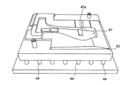
- FIG. 14 shows a lower mold in which a blank holder 45 is supported by cushion pins 44.
- An opening 45a is provided in the center of the blank holder 45, and a punch 47 is disposed in the opening 45a.
- FIG. 15 shows an upper mold, in which a die 51 having a recess 51a into which a punch 47 is inserted into a slider (not shown) is installed.
- a pad 53 is disposed in an opening 51 b provided on the bottom surface of the recessed portion 51 a of the die 51.
- the pad 53 is connected to a gas cylinder (not shown) to generate a load, and the protruding position of the pad 53 was adjusted by inserting a metal block (not shown) between the slider and the gas cylinder.
- a metal block (not shown)
- the metal plate 55 (see FIG. 16) two kinds of cold-rolled steel sheets having a tensile strength of 980 MPa class and 1180 MPa class were used as an ultra-high strength high tensile material having low ductility.
- the thickness of the metal plate 55 was 1.4 mm.
- the press molding was performed for a plurality of conditions by combining various combinations of blank holder pressure (MPa), pad range, pad pressure (MPa), pad protrusion position (%), and metal plate arrangement. These conditions are shown in Table 1.
- Invention Example 1 to Invention Example 11 in Table 1 are all within the scope of the present invention for the above-mentioned blank holder pressure, pad range, pad pressure, pad protrusion position, and metal plate arrangement.
- the conditions shown in Comparative Examples 1 to 5 include outside the scope of the present invention.
- the blank holder pressure, pad range, pad pressure, pad protrusion position, and metal plate arrangement will be described in detail below.
- the blank holder pressure is an average pressure in the region of the metal plate 55 sandwiched between the die 51 and the blank holder 45, and 0.7 MPa or more is within the scope of the present invention.
- the pad pressure is an average pressure for pressing the metal plate 55 with the punch 47 and the pad 53 in the pad pressing step, and 3 MPa or more is within the scope of the present invention.
- the pad protrusion position is such that the metal plate 55 is sandwiched between the die 51 and the blank holder 45 with the pad 53 removed, and the pad 53 is placed on the metal plate 55 when the pad 53 is installed in this state.
- the contact position was the 0% position of the pad 53, the upper direction from the origin was positive and the lower direction was the negative direction, and the molding depth was the 100% position.
- the pad protruding position is within the range of 0% to 50% within the scope of the present invention.
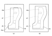
- FIG. 17A shows a case where the metal plate 55 is arranged so that the portion 55a corresponding to the short side end portion 41a of the metal plate 55 does not cover the blank holder 45, and FIG. This is the case.
- the arrangement shown in FIG. 17 (a) is within the scope of the present invention.
- the pad range was changed using three types of pads 53 shown in FIG. 18 (a) shows a part of the metal plate 55 corresponding to the bent part 41b, FIG. 18 (b) shows a part corresponding to the bent part 41b, and FIG. 18 (c). Is to suppress the entire portion corresponding to the top plate portion 41.
- the pad range shown in FIGS. 18B and 18C is the range of the present invention.
- the arc shape of the pad 53 matches the arc shape of the bent portion 41 b of the top plate portion 41.
- a portion surrounded by a dotted line in FIG. 18A and a portion surrounded by a dotted line and an arc in FIGS. 18B and 18C are an arc D, a tangent L1, and a tangent L2 in FIG. Corresponds to the enclosed part.
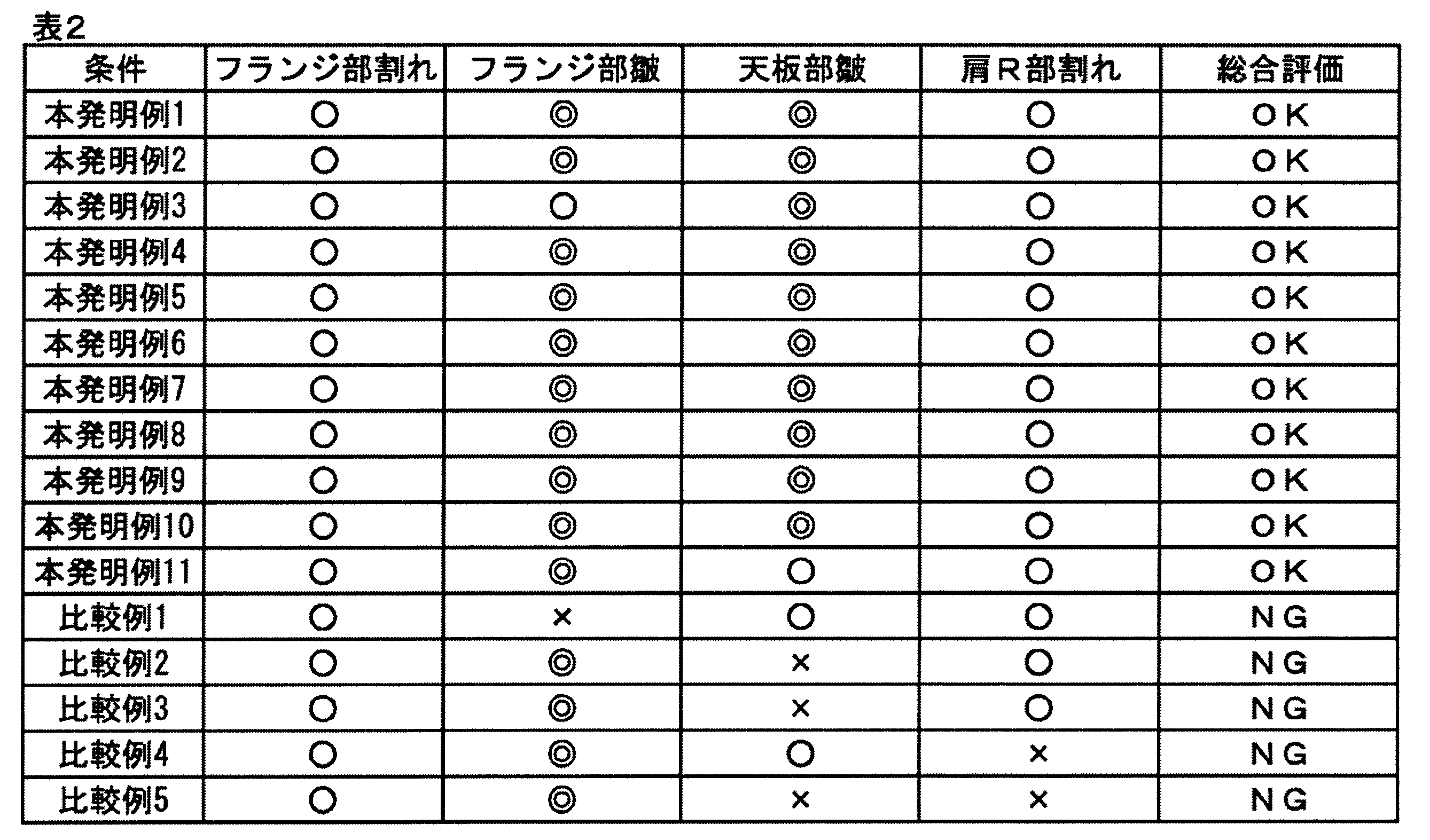
- Table 2 shows the results of press molding based on the conditions in Table 1.
- Evaluation items are cracks and creases in the flange portion 43, creases in the top plate portion 41, and cracks in the shoulder R portion of the punch 47.
- the evaluation of wrinkles was made visually.
- Table 2 the case where no wrinkle is seen is denoted by ⁇ , the case where minute wrinkle is seen is denoted by ⁇ , and the case where significant wrinkle is seen is denoted by ⁇ .
- the evaluation of cracks was also made visually.
- the case where a crack is not seen is marked as “ ⁇ ”, and the case where a crack is seen is marked as “X”.
- And comprehensive evaluation of wrinkles and cracks was performed.
- a case where the evaluation is good is indicated as OK
- a case where the evaluation is bad is indicated as NG.
- Comparative Example 4 As shown in FIG. 17 (b), the portion 55a corresponding to the short side end portion 41a of the metal plate 55 is hung on the blank holder 45, so that a crack occurs at the shoulder R portion. did.
- Comparative Example 5 since there is no pad, wrinkles are generated in the top plate portion 41, and the portion 55a corresponding to the short side end portion 41a of the metal plate 55 is applied to the blank holder 45, so the shoulder R portion Cracking occurred.
- Example 1 was an example of the front pillar 40 (part having an L-shaped part).
- the center pillar 23 (see FIGS. 9 and 10), which is a component having a T-shaped portion, was also tested because it was similar to the first embodiment.
- the pad is connected to the gas cylinder in the same manner as in the first embodiment to generate a load, and the adjustment of the protruding position of the pad is the same as in the first embodiment.
- the metal plate 35 used in the experiment is the same as that in Example 1 (tensile strength of 980 MPa class and 1180 MPa class cold-rolled steel sheet having a thickness of 1.4 mm).
- FIG. 19A shows a portion 35a, 35b, 35c, 35d corresponding to the side edge 25a, the side edge 25b, the side edge 25c, and the edge 25d of the metal plate 35 in the metal plate 35. Is arranged so as not to cover the blank holder 33, and FIG. 19B is a case arranged in such a manner.
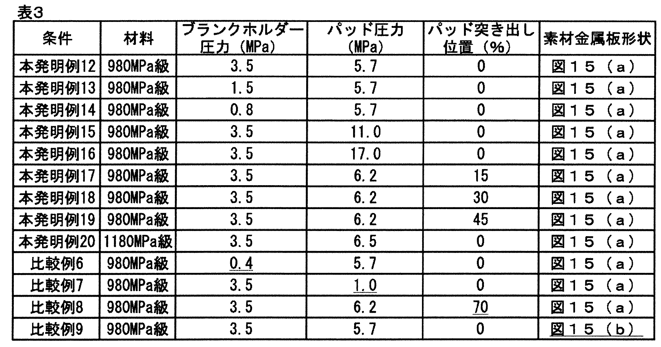
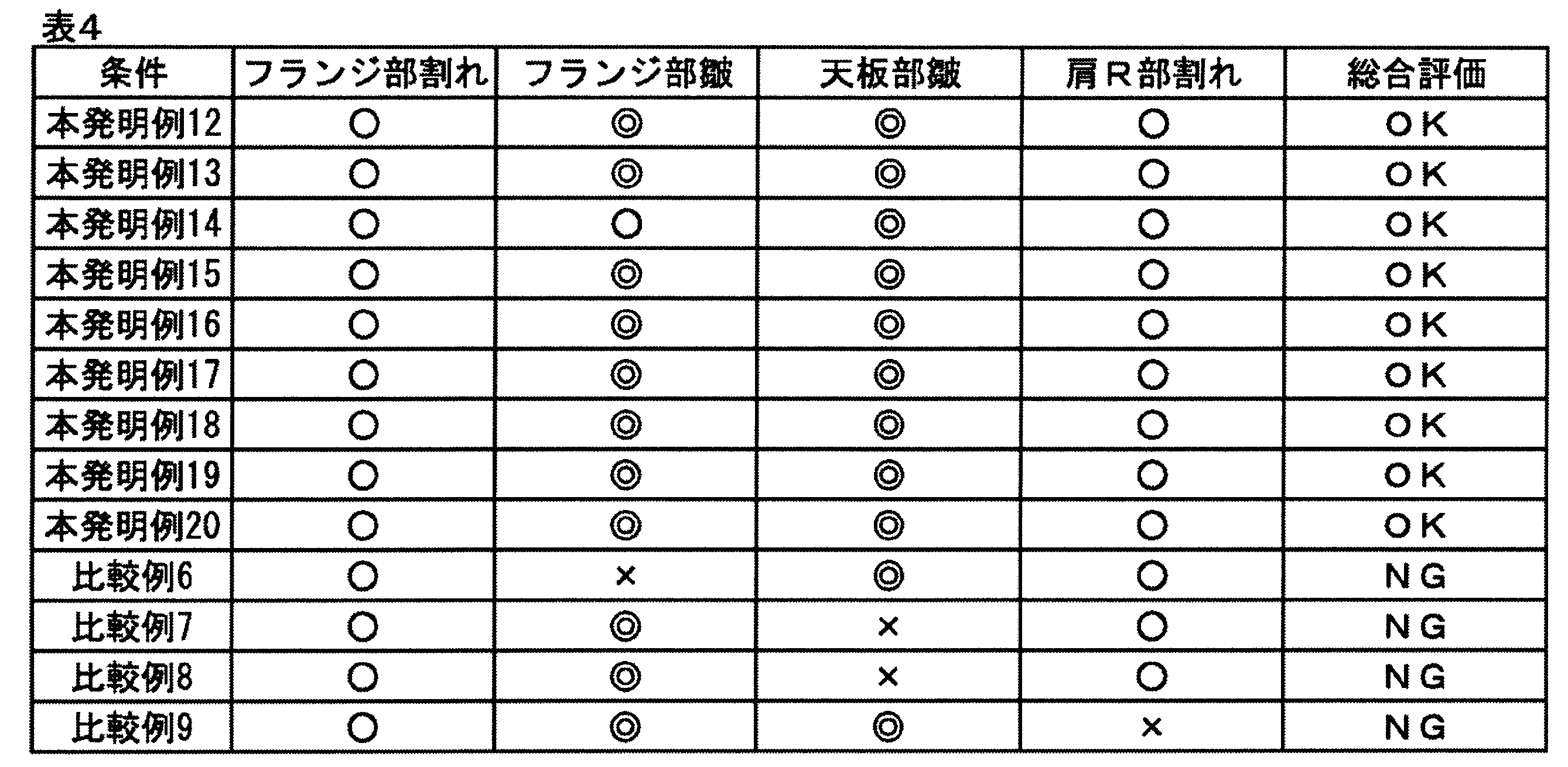
- FIG. 19 (a) The arrangement shown in FIG. 19 (a) is within the scope of the present invention. Note that in all of Invention Example 12 to Invention Example 20 and Comparative Example 6 to Comparative Example 9 in Table 3, the pad range is set to hold the connecting portion 25e surrounded by the middle thick line shown in FIG.
- the conditions shown in Invention Example 12 to Invention Example 20 are conditions in which the above-mentioned blank holder pressure, pad pressure, pad protrusion position, and metal plate arrangement are all within the scope of the present invention.
- Comparative Examples 6 to 9 are conditions including those outside the scope of the present invention.
- Table 4 shows the results of press molding based on the conditions in Table 3.
- the pad protrusion position was 70%, and the timing at which the metal plate 35 was started to be pressed by the pad was late, so that wrinkles on the top plate portion 25 could not be suppressed.
- the metal plate 35 corresponds to the lateral edge portion 25a, the lateral edge portion 25b, the lateral edge portion 25c, and the lateral edge portion 25d in the metallic plate 35 as shown in FIG. Since 35a, 35b, 35c, and 35d are applied to the blank holder 33, the shoulder R portion was cracked.
- the center pillar 23 (part having a T-shaped portion) is press-formed, even if an ultra-high strength high-tensile material having low ductility is used, the number of forming steps is not increased. It was possible to suppress wrinkles and avoid cracks.
Landscapes
- Engineering & Computer Science (AREA)
- Mechanical Engineering (AREA)
- Shaping Metal By Deep-Drawing, Or The Like (AREA)
- Forging (AREA)
Abstract
Description
本発明の第1の実施形態に係るプレス成形方法(図1参照)は、図2及び図3に示すL字形状部品1を、図4及び図5に示すプレス成形金型5を用いてプレス成形する方法である。プレス成形方法について説明する前に、L字形状部品1及びプレス成形金型5について説明する。以下に、L字形状部品1について概説する。
パンチ6は、図4に示すように、平面視でL字形状の成形面6aを有しており、ブランクホルダー9に設けられた開口部9aに配置されている。
ダイ7の中央部は、図4に示すようにL字形状に凹陥しており、該凹陥の内面がパンチ6に対応する成形面7aになっている。成形面7aにおけるL字形状の屈曲部を含む位置には開口部7bが設けられており、この開口部7bにパッド11が配置されている(図5及び図6参照)。ダイ7の下面はブランクホルダー9との間で金属板17を挟持する挟持面7cになっている。
ブランクホルダー9の中央には、開口部9aが設けられており、開口部9aにパンチ6が配置されている。ブランクホルダー9は、図5に示すように、クッションピン(cushion pin)19によって上下動可能に支持されている。ブランクホルダー9は、常時はパンチ6の上面よりも上方に位置するように支持されており、プレス成形時はダイ7によって押し下げ可能になっている。ブランクホルダー9が押し下げられると、パンチ6が相対的にブランクホルダー9から突き出して、パンチ6の上部がダイ7に挿入されるようになっている(図1(c)参照)。
パッド11は、図5に示すように、ガスシリンダー(gas cylinder)21等によってパンチ6側に押圧可能に設けられており、パンチ6と協働して金属板17における天板部2(図2参照)の一部を挟持する。パッド11の形状は、図6に示すように、金属板17における屈曲部2b(図2参照)に相当する部位を押圧可能になっている。こうすることで、屈曲部2bにおける皺の発生を抑制することができる。なお、図7に示すように、屈曲部2bの内側に形成された円弧Dと、円弧Dの両端における接線L1及び接線L2で囲まれた部分に最も皺が発生しやすく、パッド11は該部分の面積Sの8割以上を押圧することが好ましい。
金属板配置工程は、図8に示すように、金属板17を、金属板17における短辺端部2aに相当する部位17aをブランクホルダー9にかからないように配置する工程である。短辺端部2aに相当する部位17aがブランクホルダー9にかかるようにしてプレス成形すると、該部位での金属板17への負荷が大きく、金属板17におけるパンチ6の肩部に対応する部位に割れが発生したり、部品コーナー付近のフランジ部4に皺が発生したりする。そこで、上記のように金属板17を配置して割れや皺の発生を回避する。
金属板挟持工程は、金属板配置工程によってブランクホルダー9上に配置された金属板17をダイ7とブランクホルダー9とで挟持する工程である。このように、金属板17をダイ7とブランクホルダー9とで挟持する理由は、フランジでの皺の発生を抑制するためである。ダイ7とブランクホルダー9とで挟持しない場合には、パンチ6が押込まれていくと、部品形状の変化部周辺では金属板17のうち自由に動ける部分が流れ込んできて、皺が発生しやすくなる。特に、部品のフランジ部4(図2参照)となる金属板17の端部付近では、金属板17が容易に変形できるため大きな皺が発生する。このため、プレス成形初期から金属板17をダイ7とブランクホルダー9とで押さえることが必要となる。なお、ダイ7とブランクホルダー9とで金属板17を押さえる平均圧力(ブランクホルダー圧力)は、0.7MPa以上とすることが望ましい。
成形工程は、ダイ7とブランクホルダー9とで挟持された状態の金属板17に対してパンチ6を押し付けて金属板17を絞り加工で成形する工程である。
パッド押え工程は、金属板挟持工程の後、成形工程途中においてパンチ6とパッド11とによって金属板17における屈曲部2bに相当する部位を含む位置を押える工程である。このように、パンチ6とパッド11とによって金属板17を押さえることは、屈曲部2b(図7参照)における皺の発生を抑制するのに有効である。パンチ6とパッド11とで金属板17を押さえる範囲(パッド範囲)は少なくとも屈曲部2b(図2参照)とすれば、皺の発生が問題となるところを押さえることができる。さらに広い範囲で天板部2を押さえてもよい。
L字形状部を有する部品の他に、T字形状部を有する部品についても同様に本発明は適用可能である。図9に、T字形状部を有する部品の一例として、自動車車体(automotive body)のセンターピラーリンフォースメント(以下、単に「センターピラー23」という)を示す。センターピラー23は、図9に示すように、平面視で、T字形状部を2つ有する天板部25と、天板部25の周囲に形成された縦壁部27と、縦壁部27に連続して形成されたフランジ部29と、を備え、図10に示すように断面が略ハット形になっている。センターピラー23の全体形状は、2つのT字形状の縦辺同士を連結した形状になっている。各T字形状の横辺の両端部(横辺端部25a、横辺端部25b、横辺端部25c、及び横辺端部25d)には縦壁部27及びフランジ部29は形成されていない。

L1、L2 接線
S 面積
1 L字形状部品
2 天板部
2a 短辺端部
2b 屈曲部
3 縦壁部
4 フランジ部
5 プレス成形金型
6 パンチ
6a 成形面
7 ダイ
7a 凹陥部
7b 開口部
7c 挟持面
9 ブランクホルダー
9a 開口部
11 パッド
13 ボルスター
15 スライダ
17 金属板
17a 部位
19 クッションピン
21 ガスシリンダー
23 センターピラー
25 天板部
25a、25b、25c、25d 横辺端部
25e 連結部
27 縦壁部
29 フランジ部
32 パンチ
33 ブランクホルダー
35 金属板
35a、35b、35c、35d 部位
40 フロントピラー
41 天板部
41a 短辺端部
41b 屈曲部
42 縦壁部
43 フランジ部
44 クッションピン
45 ブランクホルダー
45a 開口部
47 パンチ
51 ダイ
51a 凹陥部
51b 開口部
53 パッド
55 金属板
55a 部位
Claims (2)
- 成形面を有するパンチと、該パンチに対応した成形面を有するダイと、該ダイとの間で金属板を挟持するブランクホルダーと、パンチと協働して前記金属板の一部を挟持するパッドと、を有するプレス成形金型を用いて、前記金属板を、天板部と、該天板部の周囲に形成された縦壁部と、該縦壁部に連続して形成されたフランジ部と、を備え、平面視でL字形状部を有する部品にプレス成形するプレス成形方法であって、
前記金属板を、該金属板における前記L字形状の短辺の端部に相当する部位を前記ブランクホルダーにかからないように配置する金属板配置工程と、
該金属板配置工程によってブランクホルダー上に配置された前記金属板を前記ダイと前記ブランクホルダーとで挟持する金属板挟持工程と、
前記ダイと前記ブランクホルダーとで挟持された状態の前記金属板に対してパンチを押し付けて前記金属板を絞り加工で成形する成形工程と、
前記金属板挟持工程の後、前記成形工程途中において前記パンチと前記パッドとによって前記金属板における前記天板部に相当する部位の少なくともL字形状の屈曲部を含む位置を押えるパッド押え工程と、を有し、
該パッド押え工程は、前記成形工程における前記パンチが前記金属板に接触を開始した位置から下死点位置までの成形深さに対して0%から50%の位置で開始し、
前記金属板挟持工程における前記ダイと前記ブランクホルダーとで前記金属板を押さえる平均圧力を0.7MPa以上とし、
前記パッド押え工程における前記パンチと前記パッドとで前記金属板を押さえる平均圧力を3MPa以上としたことを特徴とするプレス成形方法。 - 成形面を有するパンチと、該パンチに対応した成形面を有するダイと、該ダイとの間で金属板を挟持するブランクホルダーと、パンチと協働して前記金属板の一部を挟持するパッドと、を有するプレス成形金型を用いて、前記金属板を、天板部と、該天板部の周囲に形成された縦壁部と、該縦壁部に連続して形成されたフランジ部と、を備え、平面視でT字形状部を有する部品にプレス成形するプレス成形方法であって、
前記金属板を、該金属板における前記T字形状の横辺の端部に相当する部位を前記ブランクホルダーにかからないように配置する金属板配置工程と、
該金属板配置工程によってブランクホルダー上に配置された前記金属板を前記ダイと前記ブランクホルダーとで挟持する金属板挟持工程と、
前記ダイと前記ブランクホルダーとで挟持された状態の前記金属板に対してパンチを押し付けて前記金属板を絞り加工で成形する成形工程と、
前記金属板挟持工程の後、前記成形工程途中において前記パンチと前記パッドとによって前記金属板における前記天板部に相当する部位の少なくともT字形状の横辺と縦辺との連結部を含む位置を押えるパッド押え工程と、を有し、
該パッド押え工程は、前記成形工程における前記パンチが前記金属板に接触を開始した位置から下死点位置までの成形深さに対して0%から50%の位置で開始し、
前記金属板挟持工程における前記ダイと前記ブランクホルダーとで前記金属板を押さえる平均圧力を0.7MPa以上とし、
前記パッド押え工程における前記パンチと前記パッドで前記金属板を押さえる平均圧力を3MPa以上としたことを特徴とするプレス成形方法。
Priority Applications (2)
| Application Number | Priority Date | Filing Date | Title |
|---|---|---|---|
| CN201480033169.5A CN105307792B (zh) | 2013-06-11 | 2014-04-24 | 冲压成型方法 |
| KR1020157033765A KR101688475B1 (ko) | 2013-06-11 | 2014-04-24 | 프레스 성형 방법 |
Applications Claiming Priority (2)
| Application Number | Priority Date | Filing Date | Title |
|---|---|---|---|
| JP2013-122360 | 2013-06-11 | ||
| JP2013122360A JP5664704B2 (ja) | 2013-06-11 | 2013-06-11 | プレス成形方法 |
Publications (1)
| Publication Number | Publication Date |
|---|---|
| WO2014199730A1 true WO2014199730A1 (ja) | 2014-12-18 |
Family
ID=52022032
Family Applications (1)
| Application Number | Title | Priority Date | Filing Date |
|---|---|---|---|
| PCT/JP2014/061581 Ceased WO2014199730A1 (ja) | 2013-06-11 | 2014-04-24 | プレス成形方法 |
Country Status (4)
| Country | Link |
|---|---|
| JP (1) | JP5664704B2 (ja) |
| KR (1) | KR101688475B1 (ja) |
| CN (1) | CN105307792B (ja) |
| WO (1) | WO2014199730A1 (ja) |
Families Citing this family (10)
| Publication number | Priority date | Publication date | Assignee | Title |
|---|---|---|---|---|
| JP6179527B2 (ja) * | 2015-01-16 | 2017-08-16 | Jfeスチール株式会社 | プレス成形方法 |
| JP6202019B2 (ja) * | 2015-02-25 | 2017-09-27 | Jfeスチール株式会社 | プレス成形方法 |
| US10603707B2 (en) | 2015-03-31 | 2020-03-31 | Jfe Steel Corporation | Press-forming method, method of manufacturing component with the press-forming method and component manufactured with the press-forming method |
| JP6376048B2 (ja) * | 2015-06-16 | 2018-08-22 | トヨタ車体株式会社 | プレス成形方法及びプレス型 |
| US11358203B2 (en) | 2016-04-04 | 2022-06-14 | Nippon Steel Corporation | Method for producing press-formed product |
| JP6969133B2 (ja) * | 2016-05-10 | 2021-11-24 | 日本製鉄株式会社 | 伸びフランジを有する成形体及びその製造方法 |
| WO2018066663A1 (ja) | 2016-10-05 | 2018-04-12 | 新日鐵住金株式会社 | プレス成形品の製造方法および製造装置 |
| JP2021041447A (ja) * | 2019-09-13 | 2021-03-18 | トヨタ自動車株式会社 | 湾曲凸部を有するハット型断面部品の製造装置および製造方法 |
| JP6753502B1 (ja) * | 2019-09-30 | 2020-09-09 | Jfeスチール株式会社 | 自動車用外板パネルのプレス成形方法及びプレス成形装置 |
| WO2021065139A1 (ja) * | 2019-10-02 | 2021-04-08 | Jfeスチール株式会社 | 自動車用外板パネルのプレス成形方法及びプレス成形装置 |
Citations (5)
| Publication number | Priority date | Publication date | Assignee | Title |
|---|---|---|---|---|
| JP2002282950A (ja) * | 2001-03-28 | 2002-10-02 | High Frequency Heattreat Co Ltd | フランジ付き部品の製造方法並びに熱処理装置及び熱処理方法 |
| JP2004344925A (ja) * | 2003-05-22 | 2004-12-09 | Nippon Steel Corp | プレス成形金型装置およびプレス成形方法 |
| JP2010036217A (ja) * | 2008-08-05 | 2010-02-18 | Sumitomo Metal Ind Ltd | センターピラーアウターパネルの製造方法およびセンターピラーアウターパネル用ブランク |
| EP2524740A1 (en) * | 2011-05-19 | 2012-11-21 | Nippon Steel Corporation | Press-forming method of component having L shape |
| JP2012232315A (ja) * | 2011-04-28 | 2012-11-29 | Honda Motor Co Ltd | 自動車のサイドパネルの製造方法 |
Family Cites Families (5)
| Publication number | Priority date | Publication date | Assignee | Title |
|---|---|---|---|---|
| JP4483933B2 (ja) * | 2007-11-21 | 2010-06-16 | トヨタ自動車株式会社 | プレス成形方法およびプレス成形装置 |
| JP2010167480A (ja) * | 2009-01-26 | 2010-08-05 | Honda Motor Co Ltd | プレス成形用金型及びプレス成形方法 |
| KR101472645B1 (ko) | 2010-05-19 | 2014-12-15 | 신닛테츠스미킨 카부시키카이샤 | L자 형상을 갖는 부품의 프레스 성형 방법 |
| ES2600402T3 (es) | 2010-11-24 | 2017-02-08 | Nippon Steel & Sumitomo Metal Corporation | Método para fabricar un producto con forma de L |
| JP2016155158A (ja) | 2015-02-25 | 2016-09-01 | ダイハツ工業株式会社 | ヘミング加工方法 |
-
2013
- 2013-06-11 JP JP2013122360A patent/JP5664704B2/ja active Active
-
2014
- 2014-04-24 KR KR1020157033765A patent/KR101688475B1/ko active Active
- 2014-04-24 CN CN201480033169.5A patent/CN105307792B/zh active Active
- 2014-04-24 WO PCT/JP2014/061581 patent/WO2014199730A1/ja not_active Ceased
Patent Citations (5)
| Publication number | Priority date | Publication date | Assignee | Title |
|---|---|---|---|---|
| JP2002282950A (ja) * | 2001-03-28 | 2002-10-02 | High Frequency Heattreat Co Ltd | フランジ付き部品の製造方法並びに熱処理装置及び熱処理方法 |
| JP2004344925A (ja) * | 2003-05-22 | 2004-12-09 | Nippon Steel Corp | プレス成形金型装置およびプレス成形方法 |
| JP2010036217A (ja) * | 2008-08-05 | 2010-02-18 | Sumitomo Metal Ind Ltd | センターピラーアウターパネルの製造方法およびセンターピラーアウターパネル用ブランク |
| JP2012232315A (ja) * | 2011-04-28 | 2012-11-29 | Honda Motor Co Ltd | 自動車のサイドパネルの製造方法 |
| EP2524740A1 (en) * | 2011-05-19 | 2012-11-21 | Nippon Steel Corporation | Press-forming method of component having L shape |
Also Published As
| Publication number | Publication date |
|---|---|
| KR101688475B1 (ko) | 2016-12-21 |
| CN105307792B (zh) | 2017-03-08 |
| KR20160003795A (ko) | 2016-01-11 |
| JP2014240078A (ja) | 2014-12-25 |
| JP5664704B2 (ja) | 2015-02-04 |
| CN105307792A (zh) | 2016-02-03 |
Similar Documents
| Publication | Publication Date | Title |
|---|---|---|
| JP5664704B2 (ja) | プレス成形方法 | |
| US10596613B2 (en) | Producing method, producing apparatus and producing equipment line of press formed product | |
| JP6011680B1 (ja) | プレス成形方法及びプレス成形金型 | |
| KR20120140236A (ko) | L자 형상을 갖는 부품의 프레스 성형 방법 | |
| KR20160091995A (ko) | 프레스 성형 장치, 이 성형 장치를 이용한 프레스 성형품의 제조 방법, 및 프레스 성형품 | |
| JPWO2013191256A1 (ja) | プレス成形体の製造方法および製造装置 | |
| JP5708757B1 (ja) | プレス成形方法 | |
| JP2015110237A (ja) | プレス成形装置およびプレス成形方法 | |
| JP5987942B1 (ja) | プレス成形金型 | |
| JP6015784B2 (ja) | 伸びフランジ成形部品の製造方法 | |
| KR102861496B1 (ko) | 프레스 성형 금형 및 프레스 성형 방법 | |
| JP6717269B2 (ja) | 自動車用外板パネルのプレス成形方法 | |
| WO2020121591A1 (ja) | プレス成形方法 | |
| WO2017187679A1 (ja) | プレス成形方法 | |
| WO2024053186A1 (ja) | プレス成形品の製造方法 | |
| WO2020217594A1 (ja) | プレス成形方法 | |
| JP6897840B1 (ja) | プレス成形方法 | |
| JP6319382B2 (ja) | 伸びフランジ成形部品の製造方法 | |
| JP7283439B2 (ja) | プレス部品の製造方法、及び金属板 | |
| JP2016155150A (ja) | プレス成形方法 | |
| JP5609630B2 (ja) | 板金の歪み矯正装置 | |
| JP2017056463A (ja) | プレス成形方法 | |
| KR102862573B1 (ko) | 프레스 성형 방법 | |
| KR20200050197A (ko) | 경사벽부의 주름을 없앨 수 있는 프레스 성형 방법 | |
| JP2024104276A (ja) | プレス成形品の製造方法 |
Legal Events
| Date | Code | Title | Description |
|---|---|---|---|
| WWE | Wipo information: entry into national phase |
Ref document number: 201480033169.5 Country of ref document: CN |
|
| 121 | Ep: the epo has been informed by wipo that ep was designated in this application |
Ref document number: 14811392 Country of ref document: EP Kind code of ref document: A1 |
|
| ENP | Entry into the national phase |
Ref document number: 20157033765 Country of ref document: KR Kind code of ref document: A |
|
| NENP | Non-entry into the national phase |
Ref country code: DE |
|
| 122 | Ep: pct application non-entry in european phase |
Ref document number: 14811392 Country of ref document: EP Kind code of ref document: A1 |