WO2014199544A1 - クレーン装置 - Google Patents
クレーン装置 Download PDFInfo
- Publication number
- WO2014199544A1 WO2014199544A1 PCT/JP2014/001851 JP2014001851W WO2014199544A1 WO 2014199544 A1 WO2014199544 A1 WO 2014199544A1 JP 2014001851 W JP2014001851 W JP 2014001851W WO 2014199544 A1 WO2014199544 A1 WO 2014199544A1
- Authority
- WO
- WIPO (PCT)
- Prior art keywords
- mast
- frame
- connection piece
- hole
- fixing member
- Prior art date
- Legal status (The legal status is an assumption and is not a legal conclusion. Google has not performed a legal analysis and makes no representation as to the accuracy of the status listed.)
- Ceased
Links
Images





Classifications
-
- B—PERFORMING OPERATIONS; TRANSPORTING
- B66—HOISTING; LIFTING; HAULING
- B66F—HOISTING, LIFTING, HAULING OR PUSHING, NOT OTHERWISE PROVIDED FOR, e.g. DEVICES WHICH APPLY A LIFTING OR PUSHING FORCE DIRECTLY TO THE SURFACE OF A LOAD
- B66F9/00—Devices for lifting or lowering bulky or heavy goods for loading or unloading purposes
- B66F9/06—Devices for lifting or lowering bulky or heavy goods for loading or unloading purposes movable, with their loads, on wheels or the like, e.g. fork-lift trucks
- B66F9/07—Floor-to-roof stacking devices, e.g. "stacker cranes", "retrievers"
- B66F9/072—Travelling gear therefor
Definitions
- the present invention relates to a crane apparatus that can travel along a shelf for storing luggage and transfer the luggage to and from the shelf.
- an automatic warehouse equipped with a rack having a plurality of shelves and a crane device for transferring loads.
- the crane device moves left and right along the rack, and moves the transfer device up and down along the mast, thereby exchanging luggage with each of the plurality of shelves of the rack. It can be carried out.
- the lower end of the mast that guides the lifting and lowering of the transfer device is connected to the lower carriage that runs along the lower rail, and the upper end of the mast is connected to the upper carriage that runs along the upper rail. ing.
- the movement of the lower carriage and the upper carriage is synchronized so that the mast is maintained upright.
- Patent Document 1 discloses a technique in which an excessive force is not applied to the connecting portion between the mast and the lower carriage by attaching the mast to the lower carriage so as to be swingable.
- Patent Document 1 when the mast is swingably attached to the lower carriage, excessive stress generated at the connecting portion between the mast and the lower carriage is suppressed, while the mast posture is reduced. The problem that it is difficult to stabilize may arise.
- the transfer device that moves up and down along the mast stops at a position shifted from the normal position in the traveling direction as it goes up.
- the frequency of occurrence of an undesirable event from the viewpoint of, for example, the load transfer efficiency, such as re-loading of the load transfer operation (for example, repositioning of the load or fine adjustment of the position of the transfer device) increases. there is a possibility.
- the present invention has been made in consideration of the above-described conventional problems, and an object of the present invention is to provide a crane apparatus that raises and lowers a transfer apparatus along a mast and has improved reliability.
- a crane apparatus is a crane apparatus that travels along a traveling path, and extends in a vertical direction, and moves up and down of a transfer apparatus that transfers a load.
- a mast for guiding the mast, at least one wheel in contact with the travel path, a frame portion extending in the travel direction, a connecting piece connecting the mast to the frame portion, and the mast in the travel direction A shaft member that pivotally supports the connecting piece portion and the frame portion, and a fixing member that fixes the connecting piece portion to the frame portion with a predetermined fastening force.
- a fixing member that allows the connection piece to rotate around the shaft member when the applied force in the traveling direction exceeds a predetermined value.
- the mast is connected to the frame portion that moves along the traveling path via the connecting piece portion.
- the connecting piece portion and the frame portion are pivotally supported by a shaft member. Therefore, the mast can rotate around the shaft member with respect to the frame portion.
- the connecting piece is fixed to the frame by a predetermined fastening force. For this reason, the normal posture of the mast is maintained in a normal state. That is, it is possible to suppress the occurrence of useless work such as reworking of the load transfer operation, which occurs due to the mast posture being unstable.
- connection piece portion rotates with respect to the frame portion around the shaft member, so that the excessive force is released. . That is, a member such as a mast is free from damage caused by the excessive force.
- the crane device according to this aspect is a crane device that raises and lowers the transfer device along the mast, and has improved reliability.
- the crane apparatus further includes a base having at least one wheel that contacts the travel path, wherein the mast is erected on the base, and the connection piece portion May be provided on the base so as to protrude from the base in the traveling direction.
- the mast is connected to the frame portion via the base and the connecting piece, and the connecting piece is provided in a state protruding from the base in the traveling direction. That is, the mast and the frame part form an L-shaped structure as a whole.
- the transfer device can be lowered to the upper surface of the frame portion or the vicinity thereof. As a result, the load can be transferred even to a shelf arranged at a relatively low position.
- the mast is erected on a base having wheels, when the wheel is a drive wheel that is rotationally driven by a drive source such as a motor, the drive wheel is driven by the weight of the mast and the transfer device. As a result, the driving force from the driving source is efficiently transmitted to the road surface. That is, useless energy consumption such as idling of the drive wheels is suppressed.
- the crane apparatus may further include a positioning member that positions the connection piece and the frame so that the mast stands upright with respect to the traveling direction, and the connection piece And a positioning member detachable from at least one of the frame parts, and the positioning member is different from the shaft member when the connection piece and the frame part are attached to the positioning piece. It may be pivotally supported at the position.
- the mast when assembling the crane device, the mast can be easily placed in a normal posture (upright), and in this state, the connection piece portion is fixed to the frame portion by the fixing member. , Can maintain the mast in a normal posture.
- the connecting piece rotates with respect to the frame, and as a result, the positioning member is tilted from the upright state. Can easily return the mast to an upright state.
- the crane apparatus which concerns on 1 aspect of this invention is further interposed in the direction which can rotate with respect to the said frame part of the said connection piece part between the said frame part and the said connection piece part,
- the said connection It is good also as providing the control member which controls the angle of rotation centering on the said shaft member of one part.
- the rotation angle of the connecting piece that is, the mast rotation angle
- the rotation angle of the connecting piece can be minimized.
- the occurrence of problems such as the crane device being unable to travel due to the large inclination of the mast is suppressed.
- the crane apparatus which concerns on 1 aspect of this invention WHEREIN:
- the 1st through-hole which the said fixing member penetrates is formed in the said connection piece part,
- a through hole is formed, and the fixing member passes the first through hole and the second through hole in a direction crossing the traveling direction and the vertical direction, and the connection piece portion is inserted into the frame.
- the connecting piece portion is pivoted about the shaft member because the inner diameter of at least one of the first through hole and the second through hole is larger than the outer diameter of the fixing member. It may be acceptable.
- the fixing member is realized by a simple and easy-to-handle member such as a bolt. Further, the fastening force between the connecting piece portion and the frame portion can be adjusted by adjusting the torque at the time of fastening the bolt. That is, it is possible to easily adjust the fastening force so as to allow rotation about the shaft member of the connection piece portion under a predetermined condition.
- FIG. 1 is a perspective view showing a configuration outline of an automatic warehouse in the embodiment.
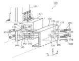
- FIG. 2 is a perspective view showing a configuration outline of the lower carriage in the embodiment.
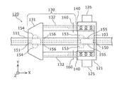
- FIG. 3A is a plan view of the lower carriage in the embodiment.
- FIG. 3B is a side view of the lower carriage in the embodiment.
- FIG. 4 is an exploded perspective view of the periphery of the connecting piece of the lower carriage in the embodiment.
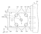
- FIG. 5 is a diagram illustrating an example of a position and size relationship between the first through hole and the second through hole in the embodiment.
- FIG. 6 is a diagram illustrating a relative shift between the second through hole and the fixing member in the embodiment.
- FIG. 7 is a diagram illustrating an aspect of attachment of the restriction member to the frame in the embodiment.
- FIG. 8 is a diagram illustrating an angle at which the mast can be rotated in the embodiment.
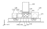
- FIG. 9 is a side view showing an example of the lower carriage when the mast is installed above the frame part.
- FIG. 1 is a perspective view showing a configuration outline of an automatic warehouse 200 in the embodiment.
- FIG. 2 is a perspective view showing a configuration outline of the lower carriage 120 in the embodiment.
- the automatic warehouse 200 includes a rack 210 having a plurality of shelves 201 and a crane apparatus 100 that travels along a travel path disposed along the rack 210.
- the rack 210 holds the luggage 202 side by side in the vertical direction (Z-axis direction) and one horizontal direction (X-axis direction), and independently loads and removes the luggage 202 in the other horizontal direction (Y-axis direction). It is a structure that can
- the crane apparatus 100 includes a mast 103, a frame part 130, a connection piece part 140 that connects the mast 103 to the frame part 130, a shaft member 160 that pivotally supports the connection piece part 140 and the frame part 130, and a connection piece part. And a fixing member 170 for fixing 140 to the frame unit 130.
- the mast 103 extends in the vertical direction and guides the lifting and lowering of the transfer device 102 that transfers the load 202.
- Frame portion 130 has at least one wheel that extends in the traveling direction (X-axis direction in the present embodiment) and contacts the traveling path.
- the shaft member 160 pivotally supports the connection piece portion 140 and the frame portion 130 so that the mast 103 can rotate in the traveling direction.
- the fixing member 170 fixes the connecting piece 140 to the frame part 130 with a predetermined fastening force, and when the force in the traveling direction applied to the mast 103 exceeds a predetermined value, the fixing member 170 is centered on the shaft member 160 of the connecting piece 140. Rotation is allowed.
- the upper carriage 114 and the lower carriage 120 move in the left-right direction (X-axis direction), and the lifting platform 104 moves in the vertical direction (Z-axis direction) along the mast 103.
- the cargo 202 is transported.
- the crane apparatus 100 can move the transfer apparatus 102 to the front of each shelf 201 of the rack 210 by the above operation. Thereby, the crane apparatus 100 can take out an arbitrary load 202 from the rack 210 and place the load 202 at an arbitrary position on the rack 210.
- the lower carriage 120 is a traveling vehicle that moves along the traveling path and causes the crane apparatus 100 to travel in the horizontal direction (X-axis direction).
- lower cart 120 includes travel motor 125 and travels horizontally on lower rail 111, which is an example of a travel path, laid on the floor of the building.
- the lower carriage 120 includes a frame portion 130 and a base 121 connected to the frame portion 130 by a connection piece 140, and the mast 103 stands on the base 121. It is installed. That is, in the present embodiment, the mast 103 is connected to the frame part 130 via the base 121 and the connection piece part 140.
- the upper carriage 114 includes a traveling motor (not shown), and travels in the horizontal direction along the upper rail 113 disposed in the upper part of the building.
- the lower cart 120 and the upper cart 114 are controlled by a controller (not shown) that controls the automatic warehouse 200 so as to move in synchronization. That is, the lower carriage 120 and the upper carriage 114 are controlled so that the mast 103 moves in the horizontal direction (X-axis direction) in a state where the mast 103 maintains an upright attitude (attitude parallel to the Z-axis). .
- the mast 103 rotates by allowing the connection piece 140 to rotate. As a result, the large stress is released, thereby protecting the member such as the mast 103.
- a characteristic configuration of the crane apparatus 100 in the embodiment, such as the connection piece 140, will be described later with reference to FIGS. 3A to 8.
- the transfer device 102 is a device that transfers the load 202 between the rack 210 and the crane device 100.
- the transfer device 102 employs a scalar arm method in which the load 202 is transferred by an articulated arm unit.
- the transfer device 102 can transfer the load 202 to and from the rack 210 even in a narrow space by rotating the arm unit at the joint.
- another rack 210 may be arranged on the opposite side of the rack 210 with the crane device 100 interposed therebetween so as to face the rack 210.
- the transfer device 102 can transfer the load 202 to the other rack 210.
- the lifting platform 104 is slidably attached to the mast 103 in the vertical direction, and is lifted by a lifting motor 126 disposed on the base 121. That is, the transfer device 102 attached to the lifting platform 104 is guided up and down by the mast 103.
- FIG. 3A is a plan view of the lower carriage 120 in the embodiment
- FIG. 3B is a side view of the lower carriage 120 in the embodiment.
- the lower carriage 120 includes a frame portion 130 and a base 121 on which the mast 103 is erected.
- the frame unit 130 includes a cart unit 131 and a pair of frames 132 that connect the cart unit 131 and the base 121.
- the carriage unit 131 has at least one wheel.
- the auxiliary wheel 151 that rotates in contact with the upper surface of the I-shaped lower rail 111, and a pair of horizontal wheels arranged so as to sandwich the lower rail 111 from both sides in the width direction (Y-axis direction). It has a roller 154 and a pair of anti-lifting rollers 156 that prevent the carriage unit 131 from floating up.
- the base 121 is a cart that supports the mast 103 and has at least one wheel.
- the base 121 is a cart that drives the traveling of the lower cart 120.
- the lower cart 120 is provided with the traveling motor 125 as described above, and the main wheel 150 is rotationally driven by the traveling motor 125 so that the lower cart 120 is attached to the lower rail 111. Drive along.
- the base 121 further includes a pair of horizontal rollers 153 disposed so as to sandwich the lower rail 111 from both sides in the width direction (Y-axis direction), and a pair of lift prevention rollers 155 for preventing the base 121 from being lifted. And have.
- connection piece part 140 The frame part 130 and the base 121 having such a configuration are connected by the connection piece part 140.
- the connecting piece 140 is provided on the base 121 so as to protrude from the base 121 in the traveling direction. Specifically, the connection piece 140 is attached to the base 121 with a plurality of bolts at positions corresponding to the pair of frames 132 of the frame 130 on the base 121.
- connection piece part 140 since the aspect of the connection between the frame part 130 and the base 121 is the same in each of the two connection piece parts 140, the following will focus on one connection piece part 140 and the connection piece part 140 and its surroundings. The structural features and the like will be described.
- connection piece 140 and the frame 130 are pivotally supported by the shaft member 160.
- the shaft member 160 is conceptually illustrated by a one-dot chain line.
- connection piece 140 is fixed to the frame part 130 by a fixing member 170.
- the connection piece 140 is fixed by four fixing members 170 arranged around the shaft member 160.
- the fixing member 170 is realized by a bolt that fastens the connection piece 140 and the frame 130.
- FIG. 4 is an exploded perspective view of the periphery of the connecting piece 140 of the lower carriage 120 in the embodiment.
- the frame 132 is shown in a cutaway view.
- the shaft member 160 is connected in a state of passing through the first shaft hole 133 provided in the frame 132 of the frame portion 130 and the second shaft hole 143 provided in the connection piece portion 140.
- the piece part 140 and the frame part 130 are pivotally supported.
- the shaft member 160 is fixed to the frame 132 by a member (not shown) such as a screw that passes through the frame 132 and is partially inserted into the shaft member 160.
- each of the plurality of fixing members 170 passes through the first through hole 135 provided in the frame 132 and the second through hole 145 provided in the connection piece 140 and is screwed into the corresponding nut 171.
- the connection piece 140 is fixed to the frame 130 with a predetermined fastening force.
- connection piece 140 is fixed to the frame 130 so that the rotation of the connection piece 140 around the shaft member 160 is allowed under a predetermined condition.
- a fixing mechanism will be described later with reference to FIGS.
- the crane apparatus 100 of the present embodiment includes a positioning member 180 that positions the connecting piece 140 and the frame 130. Specifically, the positioning member 180 passes through the first positioning hole 139 provided in the frame 132 and the second positioning hole 149 provided in the connection piece 140, so that the mast 103 can move in the traveling direction.
- the connecting piece 140 and the frame 130 are positioned so as to stand upright.
- the positioning member 180 when the positioning member 180 is attached to the connection piece 140 and the frame part 130, the positioning member 180 pivotally supports the connection piece 140 and the frame part 130 at a position different from the shaft member 160.
- the connecting piece 140 is fixed to the frame portion 130 by the plurality of fixing members 170 in a state where the positioning member 180 penetrates the connecting piece portion 140 and the frame 132 of the frame portion 130. Is done. Thereafter, the positioning member 180 is extracted from the connection piece 140 and the frame 130.
- the crane apparatus 100 is assembled in a state where the mast 103 is in a normal posture (a posture standing upright with respect to the traveling direction (X-axis direction)).
- the positioning member 180 is illustrated as being separated from each of the connection piece 140 and the frame portion 130. However, the positioning member 180 may be provided so as to be removable from only one of the connection piece 140 and the frame 130.
- the positioning member 180 may be connected to the frame part 130 or the connection piece part 140 by a wire, a chain, or a rotating arm.
- the positioning member 180 only needs to be detachable from at least one of the connection piece 140 and the frame 130.
- connection piece 140 is not completely fixed to the frame portion 130 by the fixing member 170, and is allowed to rotate around the shaft member 160 under a predetermined condition. Fixed to.
- FIG. 5 is a diagram illustrating an example of a position and size relationship between the first through hole 135 and the second through hole 145 in the embodiment.
- FIG. 6 is a diagram showing a relative shift between the second through hole 145 and the fixing member 170 in the embodiment.
- FIG. 5 is a perspective view of the frame 132.
- the frame 132 is indicated by a dotted line, and the connection piece 140 is indicated by a solid line.
- the rotation axis P is a straight line that passes through the point P in FIG. 5 and is perpendicular to the paper surface (parallel to the Y axis).
- first through holes 135 are arranged at equal intervals on the circumference of the radius r from the rotation axis P.
- connection piece portion 140 second through holes 145 are arranged at positions corresponding to the four first through holes 135, respectively.
- the inner diameter of the first through hole 135 that is a round hole is substantially the same as the outer diameter of the fixing member 170 (the outer diameter of the portion that passes through the first through hole 135). 170 can be inserted without difficulty.
- the second through hole 145 is a hole having an oval cross section perpendicular to the penetrating direction (Y-axis direction), and has a maximum inner diameter larger than the outer diameter of the fixing member 170.
- the second through-hole 145 is configured such that the fixing member 170 inserted into the second through-hole 145 is relatively in the circumferential direction with the radius r centering on the rotation axis P.
- the shape and size are movable.
- connection piece 140 can move in the circumferential direction centered on P with respect to the fixing member 170 inserted into the second through-hole 145.
- the frame 132 and the connection piece 140 are fixed by a predetermined fastening force by the fixing member 170 so as to press each other in the Y-axis direction.
- an external force that rotates in the direction orthogonal to the Y-axis direction is applied to the connection piece 140, and the external force generates a fixing force to the frame 132 of the connection piece 140 generated by a predetermined fastening force. Assume that the number is exceeded.
- the second through hole 145 of the connection piece 140 is formed in a shape and size having a margin with respect to the outer diameter of the fixing member 170.
- the member 160 can be rotated with respect to the frame 132 (frame portion 130) around the member 160.
- the fixing member 170 crosses the first through hole 135 and the second through hole 145 in the traveling direction (X-axis direction) and the vertical direction (Z-axis direction) (in this embodiment, the Y-axis direction).
- the connecting piece 140 is fixed to the frame part 130 in a state of penetrating through the frame 130.
- the rotation of the connecting piece 140 around the shaft member 160 is allowed.
- the frame portion 130 (lower cart 120) is structurally maintained in a state parallel to the lower rail 111.
- a large force in the rotation direction about the shaft member 160 acts on the connection piece 140.
- connection piece 140 is allowed to rotate with respect to the frame 132.
- the mast 103 is stably maintained in an upright posture by the fixing member 170. Therefore, the occurrence of inefficient operations such as redoing the transfer operation of the load 202, which occurs due to the fact that the posture of the mast 103 is difficult to stabilize, is suppressed.
- the predetermined fastening force by the fixing member 170 is obtained by theoretical calculation or experiment. Specifically, when a force in the traveling direction is applied to the mast 103, the connecting piece 140 is attached to the frame 132 before plastic deformation or cracking occurs in members such as the mast 103 and the connecting piece 140. A predetermined fastening force is required so as to rotate.
- the fixing force of the fixing member 170 generated by the predetermined fastening force with respect to the connection piece 140 is obtained using the predetermined fastening force, the coefficient of friction between the connection piece 140 and the frame 132, and the like.
- the adjustment of the fastening force by the fixing member 170 is performed by, for example, adjusting the torque when the fixing member 170 is tightened in the fixing member 170 realized as a bolt.
- each fixing member 170 is retightened to fix the connection piece 140 to the frame 130.
- the crane apparatus 100 can be operated again in a state where the mast 103 is returned to the normal posture (the posture standing upright with respect to the traveling direction).
- the connecting piece 140 is provided in a state of protruding from the base 121 in the traveling direction (X-axis direction). Therefore, the mast 103 and the frame part 130 form an L-shaped structure as a whole.
- the transfer device 102 can be lowered to the upper surface of the frame portion 130 or the vicinity thereof.
- the load 202 can be transferred also to the shelf 201 arranged at a relatively low position.
- the mast 103 is erected on the base 121 having the main wheel 150 that is a drive wheel, the main wheel 150 is pressed against the road surface of the traveling path by the weight of the mast 103 and the transfer device 102. As a result, the driving force by the traveling motor 125 is efficiently transmitted to the lower rail 111. That is, useless energy consumption such as idling of the main wheel 150 is suppressed.
- the crane apparatus 100 of the present embodiment further includes a regulating member 138 that regulates the angle of rotation about the shaft member 160 of the connection piece 140.
- the regulating member 138 is interposed between the frame part 130 and the connection piece part 140 in the direction in which the connection piece part 140 can rotate with respect to the frame part 130, thereby rotating the connection piece part 140. Regulate the corners.
- two restricting members 138 are arranged on the frame 132 so as to sandwich the connection piece 140, and both clockwise and counterclockwise rotations in FIG. The moving angle is regulated.
- the clearance D is adjusted by changing the thickness of the regulating member 138, for example.
- FIG. 7 is a diagram illustrating a manner of attaching the regulating member 138 to the frame 132 in the embodiment.
- the frame 132 and the connection piece 140 are shown in a cutaway view.
- the regulating member 138 is detachably attached to the frame 132 by bolts 172.
- 7 illustrates the restriction member 138 above the connection piece 140, the restriction member 138 below the connection piece 140 is also detachably attached to the frame 132 by bolts 172.
- each regulating member 138 to a thicker regulating member 138, the clearance D can be reduced, that is, the pivotable angle of the connecting piece 140 (mast 103) can be reduced.
- each regulating member 138 to a thinner regulating member 138, the clearance D can be increased, that is, the angle at which the connecting piece 140 (mast 103) can be rotated can be increased.
- the clearance D can be adjusted according to the number of metal plates constituting the regulating member 138 by configuring the regulating member 138 with, for example, a plurality of metal plates that can be stacked.
- FIG. 8 is a diagram showing a rotatable angle of the mast 103 in the embodiment.
- the left side is the front side of the crane apparatus 100 and the right side is the rear side of the crane apparatus 100.
- connection piece 140 abuts on the regulating member 138 disposed above the connection piece 140, so that the mast 103
- the rotation angle of 103 is restricted to ⁇ clockwise.
- connection piece 140 abuts against a regulating member 138 disposed below the connection piece 140, so that the mast 103 Is rotated counterclockwise by ⁇ .
- the upper and lower clearances D of the connection piece 140 are the same.
- the mast 103 can rotate clockwise and counterclockwise, but the mast 103 can rotate clockwise.
- the counterclockwise pivotable angle may be different.
- the angle at which the connecting piece 140 can be rotated is regulated by the regulating member 138, and as a result, the angle at which the mast 103 can be pivoted is regulated.
- the occurrence of problems such as the crane device 100 being unable to travel due to the large inclination of the mast 103 is suppressed.
- the fixing member 170 penetrating the second through hole 145 contacts the inner surface of each second through hole 145, so that the connection piece 140 can be rotated. It is possible to regulate the moving angle. However, for example, as shown in FIGS. 5 and 7, the rotation angle can be more reliably regulated by arranging the regulating member 138 in the crane device 100.
- the mast 103 is set up on the base 121 that drives the traveling of the lower carriage 120.
- the mast 103 may be installed above the frame unit 130, for example.
- FIG. 9 is a side view showing an example of the lower carriage 120 when the mast 103 is installed above the frame portion 130.
- the connecting piece portion 141 and the frame portion 130 provided so as to protrude downward from the mast 103 may be pivotally supported by the shaft member 160. That is, in this case, the connection piece 141 directly connected to the mast 103 and the frame part 130 are pivotally supported by the shaft member 160, and the connection piece part 141 and the frame part 130 are supported by one or more fixing members 170. Is fixed so that rotation is allowed.
- the positioning member 180 is realized as a rod that penetrates the connection piece 140 and the frame 130.
- the positioning member 180 only needs to have a shape, structure, and strength capable of positioning the connection piece 140 and the frame 130.
- the positioning member 180 may be realized as a member that is interposed between the frame part 130 and the connection piece part 140 in the direction in which the connection piece part 140 is rotatable, like the above-described restriction member 138. Even in this case, it is possible to position the connection piece 140 in a state of being pivotally supported by the shaft member 160 (determination of the posture of the connection piece 140 with respect to the frame 132).
- the cross section of the second through hole 145 perpendicular to the through direction (Y-axis direction) is oval, but the cross section of the second through hole 145 is not particularly limited.
- the cross-sectional shape of the second through hole 145 may be, for example, a circle larger than the outer diameter of the fixing member 170, or may be a shape in which a straight line and a curve are combined.
- the rotation of the connecting piece 140 around the shaft member 160 is allowed because the inner diameter of the second through-hole 145 is larger than the outer diameter of the fixing member 170.
- the rotation of the connection piece 140 around the shaft member 160 may be allowed.
- both the first through hole 135 and the second through hole 145 may be larger than the outer diameter of the fixing member 170.
- the connection piece 140 rotate around the shaft member 160. Is possible.
- the fixing member 170 is screwed into the nut 171 to fasten the connection piece 140 and the frame portion 130.
- the nut 171 is not an essential component.
- the fixing member 170 that is a bolt.
- the fixing member 170 may not penetrate both the connection piece 140 and the frame part 130.
- the fixing member 170 may pass through the first through hole 135 of the frame 132, and the distal end portion of the fixing member 170 may be inserted into a female screw hole that does not pass through the connection piece 140.
- the first through hole 135 is formed in the frame 132 so that the inner diameter thereof is larger than the outer diameter of the fixing member 170, thereby allowing the connection piece portion 140 to rotate around the shaft member 160. be able to.
- the fixing member 170 may be realized by a fastener such as a clamp. That is, the connecting piece 140 may be fixed to the frame 132 by tightening the overlapping connecting piece 140 and the frame 132 from both sides in the overlapping direction. In this case, it is not necessary to provide a hole through which the fixing member 170 penetrates in any of the connection piece portion 140 and the frame portion 130.
- connection piece 140 is not particularly limited, and may be any one of 1 to 3, for example, or 5 or more.
- the regulating member 138 may be realized as a part of the frame 132, for example, instead of a separate member from the frame unit 130. Further, the regulating member 138 may be attached to the connection piece 140 instead of the frame part 130.
- the regulating member 138 can be attached to the crane device 100 in any manner as long as it is interposed between the frame portion 130 and the connection piece portion 140 in the direction in which the connection piece portion 140 can rotate with respect to the frame portion 130. It may be provided.
- the frame part 130 may have only the auxiliary wheel 151 as a wheel (roller).
- the frame portion 130 has a structure that can prevent displacement from the lower rail 111 in a direction that intersects the traveling direction (X-axis direction), the wheel that contacts the lower rail 111 provided in the frame portion 130. There may be only one.
- the base 121 has a structure that can prevent displacement from the lower rail 111 in a direction intersecting the traveling direction (X-axis direction), only one wheel is in contact with the lower rail 111. (Only main wheel 150) may be used.
- the automatic warehouse 200 may be used as a vault for production of industrial products or as a vault for temporarily storing various packages in a distribution warehouse.
- the transfer method of the transfer device 102 is not limited to the scalar arm method, and, for example, a fork method or a push-pull method may be employed.
- the present invention is useful as a crane device or the like for transporting luggage in an automatic warehouse.
Landscapes
- Engineering & Computer Science (AREA)
- Transportation (AREA)
- Structural Engineering (AREA)
- Civil Engineering (AREA)
- Life Sciences & Earth Sciences (AREA)
- Geology (AREA)
- Mechanical Engineering (AREA)
- Warehouses Or Storage Devices (AREA)
- Forklifts And Lifting Vehicles (AREA)
- Jib Cranes (AREA)
Abstract
下部レール(111)に沿って走行するクレーン装置(100)であって、荷物の移載を行う移載装置(102)の昇降をガイドするマスト(103)と、下部レール(111)に接触する副車輪(151)を有し、走行方向に延在するフレーム部(130)と、マスト(103)をフレーム部(130)に接続する接続片部(140)と、マスト(103)が走行方向に回動可能なように、接続片部(140)とフレーム部(130)とを軸支する軸部材(160)と、接続片部(140)をフレーム部(130)に所定の締結力により固定する固定部材(170)であって、マスト(103)に加わる走行方向の力が所定の値を超えた場合に、接続片部(140)の軸部材(160)を中心とした回動を許容する固定部材(170)とを備える。
Description
本願発明は、荷物を格納する棚に沿って走行し、棚との間で荷物の移載を行うことができるクレーン装置に関する。
従来、複数の棚を有するラックと、荷物の移載を行うクレーン装置とを備える自動倉庫が存在する。このような自動倉庫では、クレーン装置は、例えば、ラックに沿って左右に移動し、移載装置をマストに沿って昇降させることで、ラックの複数の棚のそれぞれとの間で荷物のやり取りを行うことができる。
このようなクレーン装置において、移載装置の昇降をガイドするマストの下端は、下部レールに沿って走行する下部台車と接続され、マストの上端は、上部レールに沿って走行する上部台車と接続されている。
このような構成を有するクレーン装置では、マストが直立した状態を維持するように、下部台車および上部台車の移動の同期が図られる。
しかし、下部台車および上部台車の移動を完全に同期させることは困難であり、下部台車および上部台車の移動の速度またはタイミング等にずれが生じることがある。その結果、例えば、マストと下部台車との接続部分に大きな応力が生じる場合がある。
そこで、例えば特許文献1には、マストを下部台車に対して揺動自在に取り付けることで、マストと下部台車との接続部に無理な力が加わらないようにする技術が開示されている。
しかしながら、特許文献1に示されるように、マストを下部台車に対して揺動自在に取り付けた場合、マストと下部台車との接続部に生じる過大な応力は抑制される一方で、マストの姿勢が安定し難いという問題が生じ得る。
例えば、下部台車が正規の位置で停止し、かつ、上部台車が正規の位置から少しずれた位置に停止した場合、その少しのずれは、そのままマストの傾きとして現れる。この場合、マストに沿って昇降する移載装置は、上に行けば行くほど、走行方向における正規の位置からずれた位置に停止する。
その結果、荷物の移載作業のやり直し(例えば、荷物の置きなおし、または、移載装置の位置の微調整)などの、例えば荷物の移載効率の観点から好ましくない事象の発生頻度が上昇する可能性がある。
本発明は、上記従来の課題を考慮し、マストに沿って移載装置を昇降させるクレーン装置であって、信頼性が向上されたクレーン装置を提供することを目的とする。
上記目的を達成するために、本発明の一態様に係るクレーン装置は、走行路に沿って走行するクレーン装置であって、上下方向に延在し、荷物の移載を行う移載装置の昇降をガイドするマストと、前記走行路に接触する少なくとも1つの車輪を有し、走行方向に延在するフレーム部と、前記マストを前記フレーム部に接続する接続片部と、前記マストが前記走行方向に回動可能なように、前記接続片部と前記フレーム部とを軸支する軸部材と、前記接続片部を前記フレーム部に所定の締結力により固定する固定部材であって、前記マストに加わる前記走行方向の力が所定の値を超えた場合に、前記接続片部の前記軸部材を中心とした回動を許容する固定部材とを備える。
この構成によれば、マストは、走行路に沿って移動するフレーム部に、接続片部を介して接続される。この接続片部とフレーム部とは軸部材によって軸支される。従って、マストは、フレーム部に対して軸部材を中心とした回動が可能である。
さらに、接続片部は所定の締結力によりフレーム部に固定される。そのため、通常時では、マストの姿勢は正常な姿勢に維持される。つまり、マストの姿勢が安定しないことに起因して発生する、荷物の移載作業のやり直し等の無駄な作業の発生が抑制される。
また、本態様のクレーン装置では、例えば過大な力がマストにかけられた場合には、接続片部が、軸部材を中心としてフレーム部に対して回動することで、当該過大な力が逃がされる。つまり、マスト等の部材は、当該過大な力に起因する損傷から免れる。
このように、本態様のクレーン装置は、マストに沿って移載装置を昇降させるクレーン装置であって、信頼性が向上されたクレーン装置である。
また、本発明の一態様に係るクレーン装置は、さらに、前記走行路に接触する少なくとも1つの車輪を有する基台を備え、前記マストは、前記基台に立設されており、前記接続片部は、前記基台から前記走行方向に突出するように前記基台に設けられているとしてもよい。
この構成によれば、マストは、基台および接続片部を介してフレーム部に接続され、接続片部は基台から走行方向に突出した状態で設けられる。つまり、マストとフレーム部とは全体としてL字状の構造物を形成する。
この場合、マストの下端とフレーム部との間の空間に、マストとフレーム部とを接続する部分存在しないため、例えば、フレーム部の上面またはその近傍まで移載装置を降下させることができる。その結果、比較的に低い位置に配置された棚に対しても荷物の移載が可能となる。
また、マストは、車輪を有する基台に立設されるため、当該車輪が、モータ等の駆動源に回転駆動される駆動輪である場合、マストおよび移載装置等の重量により、駆動輪が走行路の路面に押圧され、その結果、駆動源による駆動力が効率よく路面に伝達される。つまり、駆動輪の空転等の無駄なエネルギーの消費が抑制される。
また、本発明の一態様に係るクレーン装置は、さらに、前記マストが前記走行方向に対して直立するように前記接続片部と前記フレーム部とを位置決めする位置決め部材であって、前記接続片部および前記フレーム部の少なくとも一方から着脱可能な位置決め部材を備え、前記位置決め部材は、前記接続片部および前記フレーム部に装着された場合、前記接続片部および前記フレーム部を前記軸部材とは異なる位置で軸支するとしてもよい。
この構成によれば、当該クレーン装置の組み立ての際に、容易に、マストを正規の姿勢(直立)にすることができ、その状態で、固定部材で接続片部をフレーム部に固定することで、マストを正規の姿勢に維持することができる。
また、クレーン装置の使用時において、例えばマストに過大な力が加えられたことにより、接続片部がフレーム部に対して回動し、その結果、マストが直立した状態から傾いた場合、位置決め部材によって、容易に、マストを直立状態に戻すことができる。
また、本発明の一態様に係るクレーン装置は、さらに、前記接続片部の前記フレーム部に対する回動可能な方向において、前記フレーム部と前記接続片部との間に介在することで、前記接続片部の前記軸部材を中心とした回動の角度を規制する規制部材を備えるとしてもよい。
この構成によれば、接続片部の回動角、すなわち、マストの回動角を、必要最小限に抑えることができる。その結果、マストが大きく傾くことに起因してクレーン装置が走行不能になるなどの不具合の発生が抑制される。
また、本発明の一態様に係るクレーン装置において、前記接続片部には、前記固定部材が貫通する第一貫通孔が形成されており、前記フレーム部には、前記固定部材が貫通する第二貫通孔が形成されており、前記固定部材は、前記第一貫通孔と前記第二貫通孔とを、前記走行方向および前記上下方向に交差する方向に貫通した状態で前記接続片部を前記フレーム部に固定し、前記第一貫通孔および前記第二貫通孔の少なくとも一方の内径が、前記固定部材の外径よりも大きいことで、前記接続片部の前記軸部材を中心とした回動が許容されるとしてもよい。
この構成によれば、固定部材は、例えばボルトのような簡易かつ取り扱いの容易な部材で実現される。また、ボルトの締結時のトルクの調整により、接続片部とフレーム部との間の締結力の調整が可能である。つまり、所定の条件のもとで接続片部の軸部材を中心とした回動が許容されるような締結力の調整を容易に行うことができる。
本願発明によれば、マストに沿って移載装置を昇降させるクレーン装置であって、信頼性が向上されたクレーン装置を提供することができる。
以下に、本発明の実施形態のクレーン装置ついて、図面を参照しながら説明する。なお、各図は、模式図であり、必ずしも厳密に図示したものではない。
また、以下で説明する実施の形態は、包括的または具体的な例を示すものである。以下の実施の形態で示される数値、形状、材料、構成要素、構成要素の配置位置及び接続形態、ステップ、ステップの順序などは、一例であり、本発明を限定する主旨ではない。また、以下の実施の形態における構成要素のうち、最上位概念を示す独立請求項に記載されていない構成要素については、任意の構成要素として説明される。
図1は、実施の形態における自動倉庫200の構成概要を示す斜視図である。
図2は、実施の形態における下部台車120の構成概要を示す斜視図である。
図1に示すように、自動倉庫200は、複数の棚201を有するラック210と、ラック210に沿って配置された走行路に沿って走行するクレーン装置100とを備えている。
ラック210は、上下方向(Z軸方向)、および、水平の一方向(X軸方向)に荷物202を並べて保持し、水平の他方向(Y軸方向)に荷物202を独立して出し入れすることができる構造物である。
クレーン装置100は、マスト103と、フレーム部130と、マスト103をフレーム部130に接続する接続片部140と、接続片部140とフレーム部130とを軸支する軸部材160と、接続片部140をフレーム部130に固定する固定部材170とを備える。
マスト103は、上下方向に延在し、荷物202の移載を行う移載装置102の昇降をガイドする。フレーム部130は、走行方向(本実施の形態ではX軸方向)に延在し、走行路に接触する少なくとも1つの車輪を有する。
軸部材160は、マスト103が走行方向に回動可能なように、接続片部140とフレーム部130とを軸支する。
固定部材170は、接続片部140をフレーム部130に所定の締結力により固定し、マスト103に加わる走行方向の力が所定の値を超えた場合に、接続片部140の軸部材160を中心とした回動を許容する。
本実施の形態では、クレーン装置100は、上部台車114および下部台車120が左右方向(X軸方向)へ移動し、かつ、昇降台104が上下方向(Z軸方向)へマスト103に沿って移動することで、荷物202の搬送作業を行う。
つまり、クレーン装置100は、上記動作により、移載装置102をラック210の各棚201の前方に移動させることがきる。これにより、クレーン装置100は、ラック210からの任意の荷物202の取り出し、および、ラック210の任意の位置への荷物202の載置を行うことができる。
下部台車120は、走行路に沿って移動し、クレーン装置100を水平方向(X軸方向)に走行させる走行車である。本実施の形態では、下部台車120は、走行用モータ125を備え、建屋の床面に敷設された、走行路の一例である下部レール111上を水平方向に走行する。
具体的には、下部台車120は、図2に示すように、フレーム部130と、接続片部140によってフレーム部130に接続された基台121とを備え、基台121に、マスト103が立設されている。つまり、本実施の形態では、マスト103は、基台121および接続片部140を介して、フレーム部130と接続されている。
また、上部台車114は、走行用のモータ(図示せず)を備え、建屋の上部に配設された上部レール113に沿って水平方向に走行する。
さらに、下部台車120および上部台車114は同期して移動するように、自動倉庫200を制御するコントローラ(図示せず)に制御される。つまり、マスト103が走行方向に対して直立した姿勢(Z軸に平行な姿勢)を維持した状態で水平方向(X軸方向)に移動するように、下部台車120および上部台車114が制御される。
ここで、下部台車120および上部台車114の移動の完全な同期は困難であり、かつ、移載装置102が保持する荷物202の慣性およびマスト103自体の慣性などに起因し、マスト103に、走行方向(X軸方向)に過大な力がかかる場合がある。この場合、マスト103、および、マスト103と下部台車120との接続部分などに大きな応力が生じる。
このような場合、本実施の形態におけるクレーン装置100では、接続片部140の回動が許容されることで、マスト103が回動する。その結果、上記大きな応力が逃され、これにより、マスト103等の部材が保護される。
接続片部140など、実施の形態におけるクレーン装置100の特徴的な構成については、図3A~図8を用いて後述する。
移載装置102は、ラック210とクレーン装置100との間で荷物202の移載を行う装置である。本実施の形態の場合、移載装置102は、多関節のアームユニットにより荷物202の移載を行うスカラーアーム方式が採用されている。
移載装置102はアームユニットを関節において回転させることで、狭い空間でもラック210との間で荷物202の移載を行うことができる。
なお、図1では図示していないが、クレーン装置100を挟んでラック210とは反対側に、当該ラック210と対向するように他のラック210を配置することもできる。この場合、移載装置102は当該他のラック210に対しても、荷物202の移載を行うことができる。
昇降台104は、マスト103に対し上下方向に摺動自在に取り付けられており、基台121に配置された昇降用モータ126によって、昇降が駆動される。つまり、昇降台104に取り付けられた移載装置102は、マスト103によって昇降がガイドされる。
次に、実施の形態におけるクレーン装置100の詳細を、下部台車120の構造を中心に説明する。
図3Aは、実施の形態における下部台車120の平面図であり、図3Bは、実施の形態における下部台車120の側面図である。
図3Aおよび図3Bに示すように、下部台車120は、フレーム部130と、マスト103が立設された基台121とを備える。
フレーム部130は、台車部131と、台車部131および基台121を接続する一対のフレーム132とを有する。
台車部131は、少なくとも1つの車輪を有する。本実施の形態では、断面がI型の下部レール111の上面に接触して回転する副車輪151と、下部レール111を幅方向(Y軸方向)の両側から挟むように配置された一対の水平ローラ154と、台車部131の浮き上がりを防止する一対の浮上防止ローラ156とを有する。
基台121は、マスト103を支持し、少なくとも1つの車輪を有する台車である。本実施の形態では、基台121は、下部台車120の走行を駆動する台車である。
具体的には、下部台車120には、上述のように走行用モータ125が配置されており、走行用モータ125により主車輪150が回転駆動されることで、下部台車120が、下部レール111に沿って走行する。
また、基台121にはさらに、下部レール111を幅方向(Y軸方向)の両側から挟むように配置された一対の水平ローラ153と、基台121の浮き上がりを防止する一対の浮上防止ローラ155とを有する。
このような構成のフレーム部130と基台121とは、接続片部140によって接続されている。
接続片部140は、本実施の形態では、基台121から走行方向に突出するように基台121に設けられている。具体的には、基台121における、フレーム部130の一対のフレーム132に対応するそれぞれの位置に、接続片部140が複数のボルトで基台121に取り付けられている。
なお、フレーム部130と基台121との接続の態様は、2つの接続片部140のそれぞれにおいて同様であるため、以下、1つの接続片部140に着目し、当該接続片部140およびその周辺の構造的な特徴等を説明する。
本実施の形態において、接続片部140とフレーム部130とは、軸部材160によって軸支されている。なお、図3Aでは、軸部材160は、一点鎖線で概念的に図示されている。
また、接続片部140は、固定部材170によってフレーム部130に固定されている。具体的には、接続片部140は、軸部材160の周囲に配置された4つの固定部材170によって固定されている。本実施の形態では、接続片部140とフレーム部130とを締結するボルトによって、固定部材170が実現されている。
図4は、実施の形態における下部台車120の、接続片部140の周辺の分解斜視図である。なお、図4では、フレーム132は切断図で示されている。
図4に示すように、軸部材160は、フレーム部130のフレーム132に設けられた第一軸孔133と、接続片部140に設けられた第二軸孔143とを貫通した状態で、接続片部140とフレーム部130とを軸支する。
なお、軸部材160は、例えばフレーム132を貫通し軸部材160に一部が挿入されるネジなどの部材(図示せず)によって、フレーム132に固定される。
また、複数の固定部材170のそれぞれは、フレーム132に設けられた第一貫通孔135と、接続片部140に設けられた第二貫通孔145とを貫通し、対応するナット171と螺合することで、接続片部140をフレーム部130に所定の締結力で固定する。
より詳細には、所定の条件下において、接続片部140の軸部材160を中心とした回動が許容されるように、接続片部140がフレーム部130に固定される。このような固定のメカニズムについては、図5および図6を用いて後述する。
また、本実施の形態のクレーン装置100は、接続片部140とフレーム部130とを位置決めする位置決め部材180を備えている。具体的には、位置決め部材180は、フレーム132に設けられた第一位置決め孔139と、接続片部140に設けられた第二位置決め孔149とを貫通することで、マスト103が走行方向に対して直立するように接続片部140とフレーム部130とを位置決めする。
つまり、位置決め部材180は、本実施の形態では、接続片部140およびフレーム部130に装着された場合、接続片部140およびフレーム部130を軸部材160とは異なる位置で軸支する。
例えば、クレーン装置100の組み立て時において、位置決め部材180が、接続片部140とフレーム部130のフレーム132とを貫通した状態で、複数の固定部材170によって、接続片部140がフレーム部130に固定される。その後、位置決め部材180は、接続片部140およびフレーム部130から抜き出される。
これにより、マスト103が正規の姿勢(走行方向(X軸方向)に対して直立した姿勢)となった状態で、クレーン装置100が組み立てられる。
なお、図4では、位置決め部材180は、接続片部140およびフレーム部130のそれぞれから分離された状態で図示されている。しかし、位置決め部材180は、接続片部140およびフレーム部130のいずれ一方のみから取り外し可能に備えられていてもよい。
例えば、位置決め部材180が、ワイヤ、チェーン、または回動するアームによってフレーム部130または接続片部140に接続されていてもよい。
つまり、位置決め部材180は、接続片部140およびフレーム部130の少なくとも一方から着脱可能であればよい。
ここで、接続片部140は、上述のように、固定部材170によって、フレーム部130に完全には固定すされず、所定の条件下で軸部材160を中心とした回動が許容されるように固定される。
図5は、実施の形態における第一貫通孔135と第二貫通孔145との位置および大きさの関係の一例を示す図である。
図6は、実施の形態における第二貫通孔145と固定部材170との相対的なずれを示す図である。
なお、図5は、フレーム132を透視した図であり、フレーム132は点線で示され、接続片部140は実線で示されている。
図5に示すように、軸部材160の中心軸(回動軸)をPとした場合を想定する。なお、回動軸Pは、図5において点Pを通り、紙面に垂直(Y軸に平行)な直線である。
本実施の形態では、フレーム132において、回動軸Pから半径rの円周上に、等間隔に4つの第一貫通孔135が配置されている。
また、接続片部140では、これら4つの第一貫通孔135に対応するそれぞれの位置に、第二貫通孔145が配置されている。
また、丸孔である第一貫通孔135の内径は、固定部材170の外径(第一貫通孔135を貫通する部分の外径)とほぼ同一であり、第一貫通孔135に、固定部材170を無理なく挿入可能である。
また、第二貫通孔145は、貫通方向(Y軸方向)に垂直な断面が長円状の孔であり、最大内径が、固定部材170の外径よりも大きく形成されている。
より詳細には、図6に示すように、第二貫通孔145は、第二貫通孔145に挿入された固定部材170が、回動軸Pを中心とする半径rの円周方向に相対的に移動可能な形状および大きさに形成されている。
言い換えると、接続片部140は、第二貫通孔145に挿入された固定部材170に対して、Pを中心とする周方向に移動が可能である。
ここで、フレーム132と接続片部140とは、固定部材170により、Y軸方向に互いに押圧し合うように所定の締結力によって固定される。この状態において、接続片部140にY軸方向に直交する方向に回動するような外力が掛けられ、かつ、当該外力が、所定の締結力による生じる接続片部140のフレーム132に対する固定力を超えた場合を想定する。
この場合、上述のように、接続片部140の第二貫通孔145は固定部材170の外径に対して余裕をもった形状および大きさに形成されているため、接続片部140は、軸部材160を中心として、フレーム132(フレーム部130)に対して回動することができる。
すなわち、固定部材170は、第一貫通孔135と第二貫通孔145とを、走行方向(X軸方向)および上下方向(Z軸方向)に交差する方向(本実施の形態ではY軸方向)に貫通した状態で接続片部140をフレーム部130に固定している。
また、本実施の形態では、第二貫通孔145の内径が、固定部材170の外径よりも大きいことで、接続片部140の軸部材160を中心とした回動が許容される。
従って、マスト103に走行方向(X軸方向)に過大な力が加えられた場合におけるマスト103等の部材の損傷の発生は抑制される。
具体的には、マスト103に走行方向(X軸方向)に過大な力が掛けられた場合、フレーム部130(下部台車120)は、構造上、下部レール111と平行な状態に維持されるため、接続片部140には軸部材160を中心とした回動方向の大きな力が働く。
このとき、この回動方向の大きな力が、固定部材170による所定の締結力から生じる固定力を越えた場合、接続片部140は、フレーム132に対して回動が許容される。
これにより、マスト103に走行方向の力が加わることで生じる、マスト103および接続片部140等の部材で発生する応力は逃がされる。その結果、マスト103および接続片部140等の部材における損傷の発生が抑制される。
また、このようなマスト103に過大な力が加えられる状況にない通常時においては、固定部材170により、マスト103は直立した姿勢に安定的に維持される。そのため、マスト103の姿勢が安定し難いことに起因して発生する、荷物202の移載作業のやり直し等の非効率的な動作の発生が抑制される。
なお、固定部材170による上記所定の締結力は、理論計算または実験などによって求められる。具体的には、マスト103に走行方向の力が加えられた場合において、マスト103および接続片部140等の部材に、塑性変形または割れなどが生じる前に、接続片部140がフレーム132に対して回動するように、所定の締結力が求められる。
また、所定の締結力により生じる固定部材170の接続片部140に対する固定力は、当該所定の締結力、および、接続片部140とフレーム132との間の摩擦係数等を用いて求められる。
また、固定部材170による締結力の調整は、例えば、ボルトとして実現される固定部材170では、固定部材170を締め付ける際のトルクの調整によって行われる。
ここで、接続片部140がフレーム部130に対して回動した場合、つまり、マスト103が正規の姿勢から傾いた場合、各固定部材170の締結を一旦緩め、位置決め部材180(図4参照)を用いて、接続片部140とフレーム部130とを位置決めする。これにより、マスト103が正規の姿勢に戻される。
つまり、この状態で、各固定部材170を締めなおして接続片部140をフレーム部130に固定する。これにより、マスト103が正規の姿勢(走行方向に対して直立する姿勢)に戻された状態で、クレーン装置100を再度稼動させることができる。
また、本実施の形態では、接続片部140は、基台121から走行方向(X軸方向)に突出した状態で設けられている。そのため、マスト103とフレーム部130とは全体としてL字状の構造物を形成している。
つまり、マスト103の下端とフレーム部130との間の上下方向の空間に、マスト103とフレーム部130とを接続する部分が存在しない。これにより、例えば、フレーム部130の上面またはその近傍まで移載装置102を降下させることができる。その結果、比較的に低い位置に配置された棚201に対しても荷物202の移載が可能となる。
また、マスト103は、駆動輪である主車輪150を有する基台121に立設されるため、マスト103および移載装置102等の重量により、主車輪150が走行路の路面に押圧される。その結果、走行用モータ125による駆動力が効率よく下部レール111に伝達される。つまり、主車輪150の空転等の無駄なエネルギーの消費が抑制される。
また、本実施の形態のクレーン装置100はさらに、接続片部140の軸部材160を中心とした回動の角度を規制する規制部材138を備える。
具体的には、規制部材138は、接続片部140のフレーム部130に対する回動可能な方向において、フレーム部130と接続片部140との間に介在することで、接続片部140の回動角を規制する。
なお、本実施の形態では、図5に示すように、フレーム132に、接続片部140を挟むように2つの規制部材138が配置されており、図5における右回りおよび左回りの双方の回動角が規制される。
具体的には、図5に示す、規制部材138と接続片部140との間のクリアランスDを調整することで、図5における右回りおよび左回りの双方の回動角が、例えば1°に調整される。
なお、クリアランスDの調整は、例えば、規制部材138の厚みを変更することで行われる。
図7は、実施の形態における規制部材138のフレーム132への取り付けの態様を示す図である。なお、図7では、フレーム132および接続片部140は、切断図で示されている。
図7に示すように、規制部材138は、フレーム132にボルト172によって着脱可能に取り付けられる。なお、図7では、接続片部140の上方の規制部材138を図示しているが、接続片部140の下方の規制部材138も同様に、フレーム132にボルト172によって着脱可能に取り付けられる。
そのため、各規制部材138を、より厚い規制部材138に変更することで、クリアランスDを小さくすること、つまり、接続片部140(マスト103)の回動可能な角度を小さくすることができる。
また、各規制部材138を、より薄い規制部材138に変更することで、クリアランスDを大きくすること、つまり、接続片部140(マスト103)の回動可能な角度を大きくすることができる。
なお、規制部材138を、例えば、積層可能な複数の金属板で構成することで、規制部材138を構成する金属板の枚数によって、クリアランスDを調整することが可能である。
図8は、実施の形態におけるマスト103の回動可能な角度を示す図である。
ここで、図8において、左方をクレーン装置100における前方とし、右方をクレーン装置100における後方とした場合を想定する。
この場合、図8の(a)に示すように、マスト103が、後方に傾いたとき、接続片部140が、接続片部140の上方に配置された規制部材138に当接することで、マスト103の回動角は右回りにθに規制される。
また、図8の(b)に示すように、マスト103が、前方に傾いたとき、接続片部140が、接続片部140の下方に配置された規制部材138に当接することで、マスト103の回動角は左回りにθに規制される。
なお、本実施の形態では、接続片部140の上下のクリアランスDが同一であり、その結果、マスト103の右回りおよび左回りの回動可能な角度は同一であるが、マスト103の右回りおよび左回りの回動可能な角度は異なっていてもよい。
このように、本実施の形態のクレーン装置100では、接続片部140の回動可能な角度が規制部材138によって規制され、その結果、マスト103の回動可能な角度が規制される。これにより、例えば、マスト103が大きく傾くことに起因してクレーン装置100が走行不能になるなどの不具合の発生が抑制される。
ここで、仮に規制部材138が存在しない場合であっても、各第二貫通孔145の内面に、当該第二貫通孔145を貫通する固定部材170が当接することにより、接続片部140の回動角を規制することは可能である。しかしながら、例えば図5および図7に示すようにクレーン装置100に規制部材138を配置することで、当該回動角の規制をより確実に行うことができる。
以上、本発明のクレーン装置について、実施の形態に基づいて説明した。しかしながら、本発明は、上記実施の形態に限定されるものではない。本発明の趣旨を逸脱しない限り、当業者が思いつく各種変形を本実施の形態に施したものも、あるいは、上記説明された複数の構成要素を組み合わせて構築される形態も、本発明の範囲内に含まれる。
例えば、本実施の形態では、マスト103は、下部台車120の走行を駆動する基台121に立設されるとした。しかしながら、マスト103は、例えば、フレーム部130の上方に設置されてもよい。
図9は、フレーム部130の上方にマスト103が設置された場合の下部台車120の一例を示す側面図である。
例えば、図9に示すように、マスト103から下方に突出するように設けられた接続片部141とフレーム部130とが、軸部材160によって軸支されてもよい。つまり、この場合、マスト103に直接的に接続された接続片部141と、フレーム部130とが軸部材160によって軸支され、1以上の固定部材170によって、接続片部141とフレーム部130とが回動が許容されるように固定される。
この場合であっても、マスト103に走行方向(X軸方向)に過大な力が加えられた場合において、接続片部141の軸部材160を中心とした回動が許容されることで、マスト103が回動する。その結果、フレーム部130マスト103等の部材の損傷の発生は抑制される。
また、本実施の形態では、位置決め部材180は、接続片部140およびフレーム部130を貫通する棒体として実現されている。しかしながら、位置決め部材180は、接続片部140とフレーム部130とを位置決めできる形状、構造および強度を有していればよい。
例えば、位置決め部材180が、上述の規制部材138のように、接続片部140の回動可能な方向においてフレーム部130と接続片部140との間に介在する部材として実現されてもよい。この場合であっても、軸部材160に軸支された状態の接続片部140の位置決め(接続片部140のフレーム132に対する姿勢の決定)は可能である。
また、本実施の形態では、第二貫通孔145の、貫通方向(Y軸方向)に垂直な断面が長円状であるとしたが、第二貫通孔145の断面形状に特に限定はない。第二貫通孔145の断面形状は、例えば、固定部材170の外径よりも大きな円であってもよく、また、直線と曲線とが組み合わされた形状であってもよい。
また、本実施の形態では、第二貫通孔145の内径が固定部材170の外径よりも大きいことで、接続片部140の軸部材160を中心とした回動が許容されるとした。しかし、第一貫通孔135の内径が、固定部材170の外径よりも大きいことで、接続片部140の軸部材160を中心とした回動が許容されてもよい。
また、第一貫通孔135および第二貫通孔145の双方の内径が、固定部材170の外径よりも大きくてもよい。
つまり、第一貫通孔135および第二貫通孔145の少なくとも一方の内径が、固定部材170の外径よりも大きければ、接続片部140の軸部材160を中心とした回動を許容することは可能である。
また、固定部材170は、ナット171と螺合することで、接続片部140とフレーム部130とを締結するとした、しかし、ナット171は必須の構成要素ではない。例えば、接続片部140の第二貫通孔145の内面に雌ネジが形成されている場合、ボルトである固定部材170による、接続片部140とフレーム132との締結は可能である。
また、固定部材170は、接続片部140およびフレーム部130の双方を貫通しなくてもよい。
例えば、固定部材170が、フレーム132の第一貫通孔135を貫通し、固定部材170の先端部が、接続片部140を貫通していない雌ネジ穴に挿入されてもよい。この場合、第一貫通孔135を、その内径が固定部材170の外径よりも大きくなるようにフレーム132に形成することで、接続片部140の軸部材160を中心とした回動を許容することができる。
また、例えば、クランプのような締め具によって固定部材170が実現されてもよい。つまり、重ね合わされた接続片部140とフレーム132とを重ね合わせの方向の両側から締め付けるようにして接続片部140をフレーム132に固定してもよい。この場合、接続片部140およびフレーム部130のいずれにも、固定部材170が貫通する孔を設ける必要はない。
また、1つの接続片部140に対応して設置される固定部材170の個数に特に限定はなく、例えば1~3のいずれかであってもよく、5以上であってもよい。
また、規制部材138は、フレーム部130と別体の部材ではなく、例えば、フレーム132の一部として実現されてもよい。また、規制部材138が、フレーム部130ではなく、接続片部140に取り付けられていてもよい。
つまり、規制部材138は、接続片部140のフレーム部130に対する回動可能な方向において、フレーム部130と接続片部140との間に介在していれば、どのような態様でクレーン装置100に設けられてもよい。
また、フレーム部130は、車輪(ローラ)として、副車輪151のみを有していてもよい。つまり、フレーム部130は、走行方向(X軸方向)に交差する方向への下部レール111からのずれを防止できる構造を有していれば、フレーム部130が備える、下部レール111と接触する車輪は1つのみであってもよい。
また、基台121も同様に、走行方向(X軸方向)に交差する方向への下部レール111からのずれを防止できる構造を有していれば、下部レール111と接触する車輪は1つのみ(主車輪150のみ)であってもよい。
また、本実施の形態における自動倉庫200の用途に特に限定はない。例えば、工業製品の生産のための保管庫、または、物流倉庫において種々の荷物を一時的に保管するための保管庫として自動倉庫200が用いられてもよい。
また、移載装置102の移載方式としては、スカラーアーム方式に限定されることはなく、例えば、フォーク方式またはプッシュプル方式が採用されてもよい。
本願発明は、自動倉庫において荷物を搬送するクレーン装置等として有用である。
100 クレーン装置
102 移載装置
103 マスト
104 昇降台
111 下部レール
113 上部レール
114 上部台車
120 下部台車
121 基台
125 走行用モータ
126 昇降用モータ
130 フレーム部
131 台車部
132 フレーム
133 第一軸孔
135 第一貫通孔
138 規制部材
139 第一位置決め孔
140、141 接続片部
143 第二軸孔
145 第二貫通孔
149 第二位置決め孔
150 主車輪
151 副車輪
153、154 水平ローラ
155、156 浮上防止ローラ
160 軸部材
170 固定部材
171 ナット
172 ボルト
180 位置決め部材
200 自動倉庫
201 棚
202 荷物
210 ラック
102 移載装置
103 マスト
104 昇降台
111 下部レール
113 上部レール
114 上部台車
120 下部台車
121 基台
125 走行用モータ
126 昇降用モータ
130 フレーム部
131 台車部
132 フレーム
133 第一軸孔
135 第一貫通孔
138 規制部材
139 第一位置決め孔
140、141 接続片部
143 第二軸孔
145 第二貫通孔
149 第二位置決め孔
150 主車輪
151 副車輪
153、154 水平ローラ
155、156 浮上防止ローラ
160 軸部材
170 固定部材
171 ナット
172 ボルト
180 位置決め部材
200 自動倉庫
201 棚
202 荷物
210 ラック
Claims (5)
- 走行路に沿って走行するクレーン装置であって、
上下方向に延在し、荷物の移載を行う移載装置の昇降をガイドするマストと、
前記走行路に接触する少なくとも1つの車輪を有し、走行方向に延在するフレーム部と、
前記マストを前記フレーム部に接続する接続片部と、
前記マストが前記走行方向に回動可能なように、前記接続片部と前記フレーム部とを軸支する軸部材と、
前記接続片部を前記フレーム部に所定の締結力により固定する固定部材であって、前記マストに加わる前記走行方向の力が所定の値を超えた場合に、前記接続片部の前記軸部材を中心とした回動を許容する固定部材と
を備えるクレーン装置。 - さらに、前記走行路に接触する少なくとも1つの車輪を有する基台を備え、
前記マストは、前記基台に立設されており、
前記接続片部は、前記基台から前記走行方向に突出するように前記基台に設けられている
請求項1記載のクレーン装置。 - さらに、前記マストが前記走行方向に対して直立するように前記接続片部と前記フレーム部とを位置決めする位置決め部材であって、前記接続片部および前記フレーム部の少なくとも一方から着脱可能な位置決め部材を備え、
前記位置決め部材は、前記接続片部および前記フレーム部に装着された場合、前記接続片部および前記フレーム部を前記軸部材とは異なる位置で軸支する
請求項1または2に記載のクレーン装置。 - さらに、前記接続片部の前記フレーム部に対する回動可能な方向において、前記フレーム部と前記接続片部との間に介在することで、前記接続片部の前記軸部材を中心とした回動の角度を規制する規制部材を備える
請求項1~3のいずれか1項に記載のクレーン装置。 - 前記接続片部には、前記固定部材が貫通する第一貫通孔が形成されており、
前記フレーム部には、前記固定部材が貫通する第二貫通孔が形成されており、
前記固定部材は、前記第一貫通孔と前記第二貫通孔とを、前記走行方向および前記上下方向に交差する方向に貫通した状態で前記接続片部を前記フレーム部に固定し、
前記第一貫通孔および前記第二貫通孔の少なくとも一方の内径が、前記固定部材の外径よりも大きいことで、前記接続片部の前記軸部材を中心とした回動が許容される
請求項1~4のいずれか1項に記載のクレーン装置。
Priority Applications (1)
| Application Number | Priority Date | Filing Date | Title |
|---|---|---|---|
| JP2015522481A JP5983876B2 (ja) | 2013-06-10 | 2014-03-28 | クレーン装置 |
Applications Claiming Priority (2)
| Application Number | Priority Date | Filing Date | Title |
|---|---|---|---|
| JP2013122245 | 2013-06-10 | ||
| JP2013-122245 | 2013-06-10 |
Publications (1)
| Publication Number | Publication Date |
|---|---|
| WO2014199544A1 true WO2014199544A1 (ja) | 2014-12-18 |
Family
ID=52021871
Family Applications (1)
| Application Number | Title | Priority Date | Filing Date |
|---|---|---|---|
| PCT/JP2014/001851 Ceased WO2014199544A1 (ja) | 2013-06-10 | 2014-03-28 | クレーン装置 |
Country Status (3)
| Country | Link |
|---|---|
| JP (1) | JP5983876B2 (ja) |
| TW (1) | TW201509774A (ja) |
| WO (1) | WO2014199544A1 (ja) |
Cited By (1)
| Publication number | Priority date | Publication date | Assignee | Title |
|---|---|---|---|---|
| WO2025243207A1 (en) * | 2024-05-20 | 2025-11-27 | Formulatrix International Holding Ltd. | Extensible vertically-efficient laboratory automation system |
Citations (4)
| Publication number | Priority date | Publication date | Assignee | Title |
|---|---|---|---|---|
| JPH08337305A (ja) * | 1995-06-14 | 1996-12-24 | Murata Mach Ltd | 自動倉庫のスタッカークレーン |
| JP2005255352A (ja) * | 2004-03-12 | 2005-09-22 | Hitachi Kiden Kogyo Ltd | スタッカークレーンにおけるメインマストの取付方法 |
| JP2006036454A (ja) * | 2004-07-27 | 2006-02-09 | Murata Mach Ltd | スタッカークレーン |
| JP2009057183A (ja) * | 2007-09-03 | 2009-03-19 | Murata Mach Ltd | スタッカークレーン |
-
2014
- 2014-03-28 JP JP2015522481A patent/JP5983876B2/ja active Active
- 2014-03-28 WO PCT/JP2014/001851 patent/WO2014199544A1/ja not_active Ceased
- 2014-06-10 TW TW103120010A patent/TW201509774A/zh unknown
Patent Citations (4)
| Publication number | Priority date | Publication date | Assignee | Title |
|---|---|---|---|---|
| JPH08337305A (ja) * | 1995-06-14 | 1996-12-24 | Murata Mach Ltd | 自動倉庫のスタッカークレーン |
| JP2005255352A (ja) * | 2004-03-12 | 2005-09-22 | Hitachi Kiden Kogyo Ltd | スタッカークレーンにおけるメインマストの取付方法 |
| JP2006036454A (ja) * | 2004-07-27 | 2006-02-09 | Murata Mach Ltd | スタッカークレーン |
| JP2009057183A (ja) * | 2007-09-03 | 2009-03-19 | Murata Mach Ltd | スタッカークレーン |
Cited By (1)
| Publication number | Priority date | Publication date | Assignee | Title |
|---|---|---|---|---|
| WO2025243207A1 (en) * | 2024-05-20 | 2025-11-27 | Formulatrix International Holding Ltd. | Extensible vertically-efficient laboratory automation system |
Also Published As
| Publication number | Publication date |
|---|---|
| JP5983876B2 (ja) | 2016-09-06 |
| TW201509774A (zh) | 2015-03-16 |
| JPWO2014199544A1 (ja) | 2017-02-23 |
Similar Documents
| Publication | Publication Date | Title |
|---|---|---|
| TWI602772B (zh) | Stacker crane | |
| CN102198815B (zh) | 一种军用运输平台车的传输平台 | |
| US20150225216A1 (en) | Stacker crane | |
| JP6499244B2 (ja) | 搬送台車 | |
| JP5096692B2 (ja) | 重量物持上げ用ラティスブームクレーン | |
| TWI602769B (zh) | Stacker crane | |
| KR20180081544A (ko) | 캐리지 스티어링 디바이스를 사용하여 발전기의 회전자를 서비싱하기 위한 시스템 및 방법 | |
| JP5983876B2 (ja) | クレーン装置 | |
| WO2025050805A1 (zh) | 一种用于立库堆垛机的轨道装置及堆垛机系统 | |
| JP7074009B2 (ja) | 物品収納設備 | |
| JP7732418B2 (ja) | レール | |
| CN112548957A (zh) | 一种火箭发动机装配用移动支撑装置 | |
| JP2010001139A (ja) | 搬送装置及び自動倉庫 | |
| KR101143822B1 (ko) | 글라스 패널 보관장치 | |
| JP6753040B2 (ja) | スタッカクレーン | |
| JP2007238197A (ja) | 荷の昇降装置 | |
| KR20160020001A (ko) | 호이스트 | |
| CN221970747U (zh) | 对接台车 | |
| KR102854522B1 (ko) | 천정 크레인 정비용 레일 스톱퍼 장치 | |
| JP6234735B2 (ja) | 台車及び台車への対象物固定方法 | |
| JP4254135B2 (ja) | 搬送装置 | |
| JP6287700B2 (ja) | 物品搬送装置 | |
| KR20200069507A (ko) | 다면 레일을 이용한 물류 시스템 | |
| JP6226374B2 (ja) | 搬送装置 | |
| JP7611572B2 (ja) | パレットリフト |
Legal Events
| Date | Code | Title | Description |
|---|---|---|---|
| 121 | Ep: the epo has been informed by wipo that ep was designated in this application |
Ref document number: 14810559 Country of ref document: EP Kind code of ref document: A1 |
|
| ENP | Entry into the national phase |
Ref document number: 2015522481 Country of ref document: JP Kind code of ref document: A |
|
| NENP | Non-entry into the national phase |
Ref country code: DE |
|
| 122 | Ep: pct application non-entry in european phase |
Ref document number: 14810559 Country of ref document: EP Kind code of ref document: A1 |