WO2014199491A1 - 鉄道車両のドア制御システム - Google Patents
鉄道車両のドア制御システム Download PDFInfo
- Publication number
- WO2014199491A1 WO2014199491A1 PCT/JP2013/066364 JP2013066364W WO2014199491A1 WO 2014199491 A1 WO2014199491 A1 WO 2014199491A1 JP 2013066364 W JP2013066364 W JP 2013066364W WO 2014199491 A1 WO2014199491 A1 WO 2014199491A1
- Authority
- WO
- WIPO (PCT)
- Prior art keywords
- door
- stop
- vehicle
- error
- stop position
- Prior art date
Links
Images


Classifications
-
- B—PERFORMING OPERATIONS; TRANSPORTING
- B61—RAILWAYS
- B61D—BODY DETAILS OR KINDS OF RAILWAY VEHICLES
- B61D19/00—Door arrangements specially adapted for rail vehicles
- B61D19/02—Door arrangements specially adapted for rail vehicles for carriages
-
- B—PERFORMING OPERATIONS; TRANSPORTING
- B61—RAILWAYS
- B61B—RAILWAY SYSTEMS; EQUIPMENT THEREFOR NOT OTHERWISE PROVIDED FOR
- B61B1/00—General arrangement of stations, platforms, or sidings; Railway networks; Rail vehicle marshalling systems
- B61B1/02—General arrangement of stations and platforms including protection devices for the passengers
Definitions
- the present invention relates to a door control system for a railway vehicle.
- Patent Document 1 describes a train crew support system mounted on a railway or the like in which a station platform is provided on a train route and a crew member opens and closes a train side door at a stop position. This support system is stored with a position data transmitting / receiving device for acquiring position data of stations, trains, etc.
- Patent Document 2 describes a vehicle crew support device that permits a door opening operation by a crew.
- This support apparatus receives a trigger signal transmitted from an ID tag installed in front of a station home at which a vehicle stops at an ID tag transmission / reception unit, and receives a trigger signal at an ID tag transmission / reception unit before the arithmetic processing unit
- the distance traveled by the train is calculated until it is detected that the traveling speed has become zero.
- the arithmetic processing unit identifies the relative positional relationship between the stopped train and the station home based on the calculated travel distance, and trains within a predetermined stop range determined based on the station home from the positional relationship. Only when it is determined that the vehicle is stopped, the interlock of the door interlock circuit is released to permit the door opening operation by the crew.
- Patent Document 3 describes an open / close door selection system in which the reliability of the position detection method is improved.
- position detection is performed by combining a position detection method using a tachometer or the like using information from inside the vehicle and a position detection method using a GPS receiver or the like using information from the outside. If the position detection results of the two do not match, the driver or the crew is made to confirm or set the correct position.
- the door control system of the rail car of the present invention includes, for example, the home length of the stop station, the home position in the traveling direction of the rail car and the predetermined position.
- a door control system of a railway vehicle comprising: an on-vehicle memory recording stop station information including a target stop position; and an actual stop position measuring means for measuring an actual stop position with respect to a home of the stop station
- a stop error calculation device for calculating a stop error between the target stop position to be measured and the actual stop position of the rail vehicle measured by the actual stop position measuring means; and the stop station information and the actual regardless of the magnitude of the stop error. Based on the stopping position, a door on which the passenger can get on and off is determined, and the open / close door correction device that corrects the open / close door is provided.
- FIG. 1 is a view showing a door which can be opened when a train stops at a target position in the prior art.
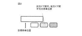
- FIG. 2 is a view showing an openable door when the train can not stop at the target stopping position in the prior art.
- FIG. 3 is a diagram illustrating an example of a block diagram of the first embodiment.
- FIG. 4 is a diagram illustrating an example of a flowchart of the first embodiment.
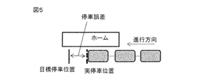
- FIG. 5 is a diagram defining a stop error when the vehicle stops at a position before the target stop position.
- FIG. 6 is a diagram defining a stop error when the target stop position is overrun and the vehicle is stopped.
- FIG. 7 is a diagram illustrating an example of a flowchart for calculating an openable / closable door in the first embodiment.
- FIG. 1 is a view showing a door which can be opened when a train stops at a target position in the prior art.
- FIG. 2 is a view showing an openable door when the train can not stop
- FIG. 8 is a diagram defining the tolerance for the target stopping position.
- FIG. 9 is a view showing a door that can be opened when the vehicle is stopped within the allowable error range with respect to the target stopping position.
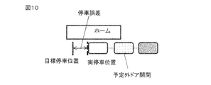
- FIG. 10 is a view showing a door that can be opened when the vehicle stops at a position closer to the target stopping position by an allowable error or more.
- FIG. 11 is a view showing a door that can be opened when the vehicle is stopped past the target stopping position by more than the allowable error.
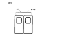
- FIG. 12 is a diagram illustrating an example of a display according to the second embodiment.
- FIG. 13 is a diagram showing an example of display content of the display unit of the second embodiment.
- FIG. 14 is a diagram illustrating an example of display content of the second embodiment.
- FIG. 15 is a diagram showing another example of the display content of the second embodiment.
- FIG. 3 is an example of a block diagram for realizing this.
- a station to be stopped next is specified based on a travel distance calculated by a railway vehicle, on-board GPS, signal information from a ground device, etc.
- Station information of a stopping station including a home position with respect to the traveling direction of the vehicle, a predetermined target stopping position, and scheduled opening / closing door information when stopping at the target stopping position is called from the on-vehicle memory 201, 202.
- the stop position error calculation device 203 calculates stop error information between the target stop position called from the in-vehicle memory 201 and the actual stop position calculated from the speed generator or the like.
- the actual stop position may be any position that can accurately identify the relationship between the home of the stop station and the actual stop position, and is provided at the traveling distance from the ground element installed immediately before the stop station, on the side of the railway vehicle.
- the start end of the home is detected by an infrared sensor or the like, and detection can be performed by various methods such as a travel distance from the start end or a difference between GPS information of a target stop position and GPS information of the stop position.
- the open / close door selection device 204 In the open / close door selection device 204, the home length of the stop station, the home position with respect to the traveling direction of the rail vehicle, and the scheduled open / close door information recorded in the on-vehicle memory 202 are called up. And select the open / close door, and give the open / close permission to the door control device 205 for opening / closing the door. With this configuration, it is possible to select the open / close door based on the error between the target stop position and the actual stop position, that is, the stop error information. That is, if the stop error information is within the allowable range, the open / close door is selected based on the open / close scheduled door information called from the on-vehicle memory 202 as that the railcar has stopped at the target stop position.
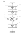
- FIG. 4 is an example of a flowchart for realizing this.
- step S301 as described in the explanation of FIG. 3, stop station information of a station at which a vehicle stops is collected from a traveling kilometer or the like.
- step S302 an error between the target stopping position of the stopping station and the actual stopping position is calculated.
- the stop error is defined as shown in FIG. 5 and FIG. That is, as shown in FIG. 5, when the vehicle traveling in the left direction stops before the stop position, the stop error is defined as negative, and the stop when the vehicle stops past the target stop position as shown in FIG. Define the error as positive.
- step S303 in FIG. 4 it is determined whether the vehicle has stopped at the station. If the vehicle has stopped, the process proceeds to step S304 to select an open / close door based on the stop error.
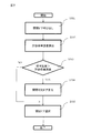
- FIG. 7 is an example of a flowchart showing an open / close door calculation method based on the calculated stop error.
- open / close scheduled door information is called from the memory based on the stop station information.
- the allowable error is calculated from the home length of the stop station, the target stop position, and the scheduled opening / closing door information.
- step S503 of FIG. 7 when the vehicle stop error is negative, the tolerance error B is compared with the absolute value, and when the vehicle stop error is plus, the tolerance error A is compared with the absolute value.
- the stopping error is larger than the allowable error, the door can not be opened in advance, so the process proceeds to step S504. Otherwise, the door recorded in the opening / closing door information is opened. Proceed to step S505.
- step S504 the door that can be opened and closed is calculated according to the stopping error and the position of the door, and the process proceeds to step S505 to open and close the door different from the predetermined door.
- FIG. 9 to 11 are schematic views of door opening and closing when the present invention is implemented.
- the door predetermined by the station information opens and closes.
- the stoppage error is larger than the allowable error A or the allowable error B
- an unexpected door opening / closing is performed. That is, in the case of this schematic view, the first and second eyes in which all the doors are intended to be opened and the third eyes in which all the doors are intended not to be opened and closed. Sends out the open / close command, and prohibits the open / close command for the door whose open / close range is partially out of the home.
- FIG. 10 shows the case where the vehicle stops before the target stopping position, and the measured distance from the rearmost side of the home to the rearmost door scheduled to be opened and closed is larger than the tolerance B, and in the second car, Open and close only the door on the front side in the direction of travel.
- the same unscheduled door opening and closing is performed, For the first door that is scheduled to be opened and closed, opening and closing instructions are prohibited for the front door, and the opening and closing instruction is sent to the third door that is not scheduled to be opened and closed.
- the door control system of the present embodiment can be mounted on a railway vehicle even on a route where infrastructure such as a ground child is not maintained by only recording station information of the installation route in the on-vehicle memories 201 and 202 in advance. it can.
- Example 2 the opening and closing door determined according to the first embodiment is presented to the passenger to realize smooth getting on and off, and door opening and closing information and guidance information presented to the passenger are shown using FIGS. explain.
- FIG. 12 shows an example of a display 801 installed on door information etc., and includes a door information display 801, which can be used by passengers by displaying information as described below. Present information.
- FIGS. 15 and 16 show an example of another display example of the door display 801.
- FIG. 15 the display contents of the display 801 above the door where the door can not be opened and closed, and unlike in FIG. 13, by displaying in which direction the openable door is located, this is displayed in advance It can prompt passengers to move quickly.
- the allowable error is negative, and in FIG. 15, a display installed on a rear vehicle prohibited from opening and closing the door displays guidance to the front in the traveling direction. Also, as shown in FIG.
- the door indicator has been described as door information, but the present invention is not limited to this, and the same information can be provided by an indicator around the door or a lamp near the door opening / closing button.
- the door side information may be transmitted from the vehicle side to the platform side, and the door side opening information and the guidance information may be displayed on the display on the platform side.
- this invention is not limited to an above-described Example, A various modified example is included.
- the embodiments described above are described in detail in order to explain the present invention in an easy-to-understand manner, and are not necessarily limited to those having all the configurations described.
- part of the configuration of one embodiment can be replaced with the configuration of another embodiment, and the configuration of another embodiment can be added to the configuration of one embodiment.
Landscapes
- Engineering & Computer Science (AREA)
- Mechanical Engineering (AREA)
- Transportation (AREA)
- Train Traffic Observation, Control, And Security (AREA)
- Platform Screen Doors And Railroad Systems (AREA)
Abstract
本発明の鉄道車両のドア制御システムは、停車駅のホーム長、鉄道車両の進行方向に対するホーム位置及び予め定められた目標停車位置を含む停車駅情報を記録した車載メモリ(201、202)と、停車駅のホームに対する実停車位置を計測する実停車位置計測手段と、車載メモリ(201、202)から得られる目標停車位置と、実停車位置計測手段が計測した車両の実停車位置との停車誤差を算出する停車誤差算出装置(203)を備えている。開閉ドア選択装置(204)は、停車誤差の大小にかかわらず、停車駅情報と実停車位置とに基づいて、乗客が乗降可能なドアを判定し、開閉ドアを補正する。
Description
本発明は、鉄道車両のドア制御システムに関する。
鉄道車両の編成数、あるいは停止駅のホーム長により、鉄道車両の編成長さが停車するホーム長よりも長い場合に、予め定められたドアを開閉することで、安全な乗降を可能にすることが必要である。
特許文献1には、列車走行路に駅ホームを設け、停車位置にて乗務員により列車側面扉を開閉する鉄道などに搭載される列車乗務員支援システムが記載されている。この支援システムは、列車の存在する駅、番線などの位置データを取得する位置データ送受信装置、基準点からの列車距離データを算出する距離データ算出手段、そして、受信した地上側データと記憶されている車両側データに基づき、駅ホーム上において当該列車の扉開閉が可能な正常停止範囲を算出する制御演算部を有し、該制御演算部は車両位置に関するデータから算出した車両位置データと正常停止範囲とを比較し、駅ホーム乗降可能側方向データを参照して乗降可能な側の開扉操作のみを許容する開扉制御手段を有している。
特許文献1には、列車走行路に駅ホームを設け、停車位置にて乗務員により列車側面扉を開閉する鉄道などに搭載される列車乗務員支援システムが記載されている。この支援システムは、列車の存在する駅、番線などの位置データを取得する位置データ送受信装置、基準点からの列車距離データを算出する距離データ算出手段、そして、受信した地上側データと記憶されている車両側データに基づき、駅ホーム上において当該列車の扉開閉が可能な正常停止範囲を算出する制御演算部を有し、該制御演算部は車両位置に関するデータから算出した車両位置データと正常停止範囲とを比較し、駅ホーム乗降可能側方向データを参照して乗降可能な側の開扉操作のみを許容する開扉制御手段を有している。
特許文献2には、乗務員による扉の開放操作を許可する車両乗務員支援装置が記載されている。この支援装置は、車両が停車する駅ホームの手前に設置されたIDタグから送信されるトリガ信号をIDタグ送受信部で受信し、IDタグ送受信部でトリガ信号を受信してから演算処理部により走行速度がゼロになったことを検出するまでの間に列車が走行した距離を演算する。演算処理部は、演算した走行距離に基づいて停車している列車と駅ホームとの相対的な位置関係を特定するとともに当該位置関係から駅ホームを基準として定められた所定の停車範囲内に列車が停車していると判定される場合にのみ、扉インタロック回路部のインタロックを解除して乗務員による扉の開放操作を許可する。
特許文献3には、位置検知方法の信頼性を向上させた開閉ドア選択システムが記載されている。この開閉ドア選択システムでは、車両内部からの情報を用いるタコジェネレータ等を用いた位置検知方法と、外部からの情報を用いるGPS受信機等を用いた位置検知方法を組み合わせて位置検知を行う。両者の位置検知結果が不一致となった場合、運転士あるいは乗務員に正しい位置を確認あるいは設定を行わせる。
しかし、先行技術文献に開示される技術では、列車が予め定められた目標停車位置に対し、許容誤差範囲内で停車した場合を前提としており、このような場合には、乗降可能なドアを開閉することができるが、目標停車位置に停車できない場合は、乗務員にその旨を警告するか、乗務員がドアの開閉動作を行ってもドアが開かないような構成になっている。
より具体的には、従来技術においては、図1に示すように、列車が目標停車位置近傍に停止した場合には、安全に乗降可能な2両目までのドアを開放し、乗客の乗降が可能となる。
しかし、図2に示すように、列車が目標停車位置に停止できず、例えば、2両目の中央部付近までがホームに到達した状態で停車したような場合、列車を移動させて、図1に示すように目標停車位置近辺に停車させることで、初めて2両目までのドアが開閉できるようになる。このため、停車位置の調整に時間を要し、列車の運行遅れの要因となる。
より具体的には、従来技術においては、図1に示すように、列車が目標停車位置近傍に停止した場合には、安全に乗降可能な2両目までのドアを開放し、乗客の乗降が可能となる。
しかし、図2に示すように、列車が目標停車位置に停止できず、例えば、2両目の中央部付近までがホームに到達した状態で停車したような場合、列車を移動させて、図1に示すように目標停車位置近辺に停車させることで、初めて2両目までのドアが開閉できるようになる。このため、停車位置の調整に時間を要し、列車の運行遅れの要因となる。
また、図2のような停車位置の場合でも、緊急時にはドアを緊急開放する機能はあるものの、ホームに面していないドアまで開放されて、安全な乗降を確保できないおそれがあるため、安易に緊急開放を行うことは困難である。
さらに、車両故障や、先行車両の在線等により、車両を目標停車位置まで移動させることができない場合には、列車の停車位置を調整すること自体が不可能となる。このため列車が、事故や車両故障により、目標停車位置に停車できないような緊急事態が発生すると、乗客が長時間にわたり列車に閉じ込められる要因の一つとなっていた。
さらに、車両故障や、先行車両の在線等により、車両を目標停車位置まで移動させることができない場合には、列車の停車位置を調整すること自体が不可能となる。このため列車が、事故や車両故障により、目標停車位置に停車できないような緊急事態が発生すると、乗客が長時間にわたり列車に閉じ込められる要因の一つとなっていた。
また、地形やインフラ未整備等の事情により、駅毎にホーム長が異なる路線や、ダイヤ毎に車両編成数が異なる路線が数多く存在する諸外国の場合、列車の停止位置の変動にかかわらず、安全に乗降できるドアのみが確実に開放されるようにするための負担が高く、運行遅れの大きな原因のひとつとなっている。
そこで、本発明の目的は、列車停車位置が目標停車位置から大きくずれた場合でも、乗客が安全に乗降可能なドアを自動的に判別して開閉ドアを補正することで、列車停止位置を修正することなく、スムースな乗降を可能にすることにある。
そこで、本発明の目的は、列車停車位置が目標停車位置から大きくずれた場合でも、乗客が安全に乗降可能なドアを自動的に判別して開閉ドアを補正することで、列車停止位置を修正することなく、スムースな乗降を可能にすることにある。
この課題を解決するため、例えば特許請求の範囲に記載の構成を採用する。
本願は上記課題を解決する手段を複数含んでいるが、その一例を挙げるならば、本発明鉄道車両のドア制御システムは、停車駅のホーム長、鉄道車両の進行方向に対するホーム位置及び予め定められた目標停車位置を含む停車駅情報を記録した車載メモリと、前記停車駅のホームに対する実停車位置を計測する実停車位置計測手段とを備えた鉄道車両のドア制御システムにおいて、前記車載メモリから得られる目標停車位置と、前記実停車位置計測手段が計測した鉄道車両の実停車位置との停車誤差を算出する停車誤差算出装置と、前記停車誤差の大小にかかわらず、前記停車駅情報と前記実停車位置とに基づいて、乗客が乗降可能なドアを判定し、開閉ドアを補正する開閉ドア補正装置を備えるようにした。
本願は上記課題を解決する手段を複数含んでいるが、その一例を挙げるならば、本発明鉄道車両のドア制御システムは、停車駅のホーム長、鉄道車両の進行方向に対するホーム位置及び予め定められた目標停車位置を含む停車駅情報を記録した車載メモリと、前記停車駅のホームに対する実停車位置を計測する実停車位置計測手段とを備えた鉄道車両のドア制御システムにおいて、前記車載メモリから得られる目標停車位置と、前記実停車位置計測手段が計測した鉄道車両の実停車位置との停車誤差を算出する停車誤差算出装置と、前記停車誤差の大小にかかわらず、前記停車駅情報と前記実停車位置とに基づいて、乗客が乗降可能なドアを判定し、開閉ドアを補正する開閉ドア補正装置を備えるようにした。
本発明により、駅毎にホーム長が異なる路線や、ダイヤ毎に車両編成数が異なる路線であっても、また、乗務員の運転技量によって、実停車位置が目標停車位置に対し頻繁にばらつくような場合であっても、さらには、緊急時、事故、車両故障等が原因で、鉄道車両が目標停車位置に停車できない場合であっても、開閉可能なドアが自動的に選択されるため、乗客が安全かつ早急にホームに降りることが可能となる。また、開閉予定のドアを開閉するための停車位置修正に要する時間によって発生する運行遅延を効果的に防止することができる。
以下本発明の実施形態を、図面を参照して説明する。
[実施例1]
本実施例では、図1のように列車が目標停車位置に停車した場合だけではなく、図2のように鉄道車両の停車位置が目標停車位置から大きくずれた場合でも、2両目の前方側のドアは乗客が安全に乗降可能であることから、1両目の前後ドアと、2両目の前方ドアのみ開放し、2両目の後方ドア及び3両目以降のドアの開放を禁止する。
[実施例1]
本実施例では、図1のように列車が目標停車位置に停車した場合だけではなく、図2のように鉄道車両の停車位置が目標停車位置から大きくずれた場合でも、2両目の前方側のドアは乗客が安全に乗降可能であることから、1両目の前後ドアと、2両目の前方ドアのみ開放し、2両目の後方ドア及び3両目以降のドアの開放を禁止する。
図3はこれを実現するためのブロック図の一例である。本実施例では、まず、鉄道車両で算出している走行距離あるいは車載されたGPS、もしくは地上装置からの信号情報等に基づいて、次に停車する駅を特定し、この駅のホーム長、鉄道車両の進行方向に対するホーム位置、予め定められた目標停車位置、さらには、目標停車位置に停車した場合の開閉予定ドア情報を含む停車駅の駅情報を車載メモリ201、202から呼び出す。
次に停車位置誤差算出装置203においては、車載メモリ201から呼び出した目標停車位置と、速度発電機等から算出される実停車位置との停車誤差情報を算出する。なお、実停車位置は、停車駅のホームと実際の停車位置の関係が正確に特定できるものであればよく、停車駅の直前に設置された地上子からの走行距離、鉄道車両の側面に設けた赤外線センサ等によりホームの開始端を検出し、この開始端からの走行距離、あるいは、目標停車位置のGPS情報と停車位置のGPS情報との差分など様々な手法により検出することができる。
開閉ドア選択装置204においては、車載メモリ202に記録された、この停車駅のホーム長、鉄道車両の進行方向に対するホーム位置、さらには開閉予定ドア情報を呼び出し、目標停車位置と停車誤差情報をもとに開閉ドアを選択し、ドアを開閉するドア制御装置205に開閉許可を与える。
この構成により目標停車位置と実停車位置との誤差、すなわち、停車誤差情報に基づき開閉ドアを選択することができる。すなわち、停車誤差情報が許容範囲内の場合は、鉄道車両が目標停車位置に停車したものとして、車載メモリ202から呼び出した開閉予定ドア情報に基づいて開閉ドアを選択する。
この構成により目標停車位置と実停車位置との誤差、すなわち、停車誤差情報に基づき開閉ドアを選択することができる。すなわち、停車誤差情報が許容範囲内の場合は、鉄道車両が目標停車位置に停車したものとして、車載メモリ202から呼び出した開閉予定ドア情報に基づいて開閉ドアを選択する。
一方、停車誤差情報が、例えば目標停車位置に対し数十メートル手前、あるいは数十メートル通り越したことを示していても、編成車両中、前方側車両あるいは後方側車両のドアのうち、乗客が乗降可能なドアが存在すれば、これを開放可能とする。ただし、その開放範囲が一部でもホームから外れるドアについては、開放を禁止し、重大な事故が発生した場合などに限り、これを解除する緊急開放ボタンを各車両内に別途設置することが好ましい。
図4は、これを実現するためのフローチャートの一例である。ステップS301では図3の説明で述べたように走行キロ等から車両が停車する駅の停車駅情報を収集する。ステップS302では停車駅の目標停車位置と実停車位置の誤差を算出する。
ここで停車誤差を図5、図6のように定義する。すなわち、図5のように左向きに進行している車両が、停車位置手前で停止した時の停車誤差をマイナスと定義し、図6のように車両が目標停車位置を通り越して停車した場合の停車誤差をプラスと定義する。
ここで停車誤差を図5、図6のように定義する。すなわち、図5のように左向きに進行している車両が、停車位置手前で停止した時の停車誤差をマイナスと定義し、図6のように車両が目標停車位置を通り越して停車した場合の停車誤差をプラスと定義する。
図4におけるステップS303では車両が駅に停車した否かを判定し、停車した場合にはステップS304に進み停車誤差に基づいて開閉ドアを選択する。
図7は、算出した停車誤差に基づいて、開閉ドア算出方法を示すフローチャートの一例である。ステップS501では停車駅情報に基づいて開閉予定ドア情報をメモリから呼び出す。ステップS502では停車駅のホーム長、目標停車位置、開閉予定ドア情報より許容誤差を算出する。
図8を用いて許容誤差について説明する。図8に示すように車両が目標停車位置に停車した際のホーム最前方から開閉予定の最前部ドアまでの距離を許容誤差A、ホーム最後方から開閉予定の最後部ドアまでの距離を許容誤差Bと定義する。
図7のステップS503では、停車誤差がマイナスであるときは許容誤差Bと絶対値を比較し、停車誤差がプラスのときは許容誤差Aと絶対値を比較する。ここで停車誤差が許容誤差より大きい場合は、予め定められている開閉予定ドアを開けることができないのでステップS504に進み、そうでない場合は、開閉予定ドア情報に記録されているドアを開放するためにステップS505に進む。
ステップS504では停車誤差、ドアの位置に応じて開閉可能なドアを算出し、ステップS505に進み予め決めたドアとは異なるドアを開閉する。
ステップS504では停車誤差、ドアの位置に応じて開閉可能なドアを算出し、ステップS505に進み予め決めたドアとは異なるドアを開閉する。
図9~図11は本発明を実施した際のドア開閉の模式図である。図9に示されるように、許容誤差の範囲内に車両が停車した場合は、駅情報によって予め定められたドアが開閉する。一方停車誤差が許容誤差Aあるいは許容誤差Bよりも大きい場合は予定外のドア開閉を行う。すなわち、この模式図の場合、すべてのドアが開閉予定であった1両目と2両目、そして、すべてのドアが開閉禁止予定であった3両目についても、乗客が安全に乗降できるドアに対しては開閉指令を送出し、その開閉範囲が一部でもホームから外れているドアに対しては開閉指令を禁止する。
図10は、車両が目標停車位置より手前に停車し、ホーム最後方から開閉予定の最後部ドアまでの測定距離が許容誤差Bよりも大きい場合を示しており、2両目においては、予定よりも進行方向前方側のドアのみを開閉する。
一方、図11に示すように、車両が目標停車位置を通り越し、ホーム最前方から開閉予定の最前部ドアまでの測定距離が許容誤差Aよりも大きい場合は、同じく予定外のドア開閉を行い、開閉予定であった1両目のドアに対し、前方側のドアに対しては開閉指令を禁止し、開閉予定ではなかった3両目の前方側ドアに対し開閉指令を送出する。このように進行方向に対し、前後どちら側の予定外ドアを開閉するかは、図8で定義した停車誤差の符号で決めることができる。また、どれだけのドアを前後ずらして開放可能となるかは、車両における基準位置(例えば、1両目の前端)に対するドア設置位置から算出することができる。
なお、本実施例において、例えば、鉄道車両の側面に設けた赤外線センサ等によりホームの開始端を検出して、停車誤差情報を算出することで、車両単独で停車駅における実停車位置を正確に求めることができる。したがって、予め、車載メモリ201、202に、設置路線の駅情報を記録するだけで、地上子等のインフラが整備されていない路線でも、本実施例のドア制御システムを鉄道車両に搭載することができる。
[実施例2]
本実施例では、実施例1により決定された開閉ドアを乗客に提示して、スムースな乗降を実現するもので、乗客に提示するドア開閉情報や案内情報を、図12~図15を用いて説明する。
図12は、ドアの情報などに設置される表示機801の一例を示しており、ドア情報表示器801を備え、ここに以下で説明するような情報を表示することで乗客に利用可能なドア情報を提示する。
本実施例では、実施例1により決定された開閉ドアを乗客に提示して、スムースな乗降を実現するもので、乗客に提示するドア開閉情報や案内情報を、図12~図15を用いて説明する。
図12は、ドアの情報などに設置される表示機801の一例を示しており、ドア情報表示器801を備え、ここに以下で説明するような情報を表示することで乗客に利用可能なドア情報を提示する。
図13、図14はドア表示器801の表示例の一例である。図13上段は、ドア開閉が可能なドア上方に設置されたドア表示器801に表示される内容である。また図13下段はドア開閉が不可能なドア上方に設置されたドア表示器801の表示内容である。
本構成により乗客はドアが開くか否かをドア表示器801を確認することで認識できる。
図15、図16はドア表示器801の別の表示例の一例である。本例ではドア開閉ができないドア上方の表示器801の表示内容であり、図13とは異なり、開閉可能なドアがどの方向にあるかを提示することで、これを事前に表示することで、乗客に速やかな移動を促すことができる。本例では許容誤差がマイナスの場合であり、図15では、ドア開閉が禁止された後方車両に設置された表示器で、進行方向前方のドアへの案内を表示している。また図16のように言葉でなく図的に表してもよい。本例ではドアの表示器はドア情報として説明したが、本発明はこれに限らずドア周辺の表示器もしくはドア開閉ボタン付近のランプによっても同様な情報を提供できる。
さらに、車両側からプラットホーム側に開閉ドア情報を送信し、こうしたドア開閉情報や案内情報をプラットホーム側のディスプレイで表示するようにしてもよい。
以上、実施例に即して説明したが、本発明は上記した実施例に限定されるものではなく、様々な変形例が含まれる。例えば、上記した実施例は本発明を分かりやすく説明するために詳細に説明したものであり、必ずしも説明したすべての構成を備えるものに限定されるものではない。また、ある実施例の構成の一部を他の実施例の構成に置き換えることが可能であり、また、ある実施例の構成に他の実施例の構成を加えることも可能である。また、各実施例の構成の一部について、他の構成の追加・削除・置換をすることが可能である。
201 車載メモリ2
202 車載メモリ1
203 停車誤差算出装置
204 開閉ドア選択装置
205 ドア制御装置
801 表示器
202 車載メモリ1
203 停車誤差算出装置
204 開閉ドア選択装置
205 ドア制御装置
801 表示器
Claims (5)
- 停車駅のホーム長、鉄道車両の進行方向に対するホーム位置及び予め定められた目標停車位置を含む停車駅情報を記録した車載メモリと、前記停車駅のホームに対する実停車位置を計測する実停車位置計測手段とを備えた鉄道車両のドア制御システムにおいて、
前記車載メモリから得られる目標停車位置と、前記実停車位置計測手段が計測した車両の実停車位置との停車誤差を算出する停車誤差算出装置と、前記停車誤差の大小にかかわらず、前記停車駅情報と前記実停車位置とに基づいて、乗客が乗降可能なドアを判定し、開閉ドアを補正する開閉ドア補正装置を備えたことを特徴とする鉄道車両のドア制御システム。 - 前記誤差が予め決められた所定値よりも大きい場合は、前記所定値よりも小さい場合と比較して、異なるドアを開閉することを特徴とする請求項1に記載された鉄道車両のドア制御システム。
- 前記誤差の符号に基づいて開閉動作を行うドアを進行方法の前後にずらすことを特徴とする請求項2に記載された鉄道車両のドア制御システム。
- 複数ドアの近傍にドア状態を表示する表示機を備え、開閉動作を行うドアと選択されたドアは開閉可能表示を、それ以外は開閉不可能表示を行うことを特徴とする請求項1に記載された鉄道車両のドア制御システム。
- 開閉動作を行うドアと選択されなかったドアの表示機に開閉動作を行うドアの位置情報を表示することを特徴とする請求項1に記載された鉄道車両のドア制御システム。
Priority Applications (2)
| Application Number | Priority Date | Filing Date | Title |
|---|---|---|---|
| PCT/JP2013/066364 WO2014199491A1 (ja) | 2013-06-13 | 2013-06-13 | 鉄道車両のドア制御システム |
| JP2015522348A JPWO2014199491A1 (ja) | 2013-06-13 | 2013-06-13 | 鉄道車両のドア制御システム |
Applications Claiming Priority (1)
| Application Number | Priority Date | Filing Date | Title |
|---|---|---|---|
| PCT/JP2013/066364 WO2014199491A1 (ja) | 2013-06-13 | 2013-06-13 | 鉄道車両のドア制御システム |
Publications (1)
| Publication Number | Publication Date |
|---|---|
| WO2014199491A1 true WO2014199491A1 (ja) | 2014-12-18 |
Family
ID=52021821
Family Applications (1)
| Application Number | Title | Priority Date | Filing Date |
|---|---|---|---|
| PCT/JP2013/066364 WO2014199491A1 (ja) | 2013-06-13 | 2013-06-13 | 鉄道車両のドア制御システム |
Country Status (2)
| Country | Link |
|---|---|
| JP (1) | JPWO2014199491A1 (ja) |
| WO (1) | WO2014199491A1 (ja) |
Cited By (2)
| Publication number | Priority date | Publication date | Assignee | Title |
|---|---|---|---|---|
| CN112874579A (zh) * | 2019-11-29 | 2021-06-01 | 比亚迪股份有限公司 | 列车开门判定方法和车载控制器 |
| CN115447639A (zh) * | 2022-09-22 | 2022-12-09 | 中车成都机车车辆有限公司 | 一种停车精度测试方法、装置、设备及可读存储介质 |
Families Citing this family (1)
| Publication number | Priority date | Publication date | Assignee | Title |
|---|---|---|---|---|
| DE102017000497B4 (de) * | 2017-01-20 | 2018-09-13 | Knorr-Bremse Gesellschaft Mit Beschränkter Haftung | Türmodul zur Anordnung in einer Türöffnung einer Wand eines Wagenkastens eines Schienenfahrzeugs |
Citations (4)
| Publication number | Priority date | Publication date | Assignee | Title |
|---|---|---|---|---|
| JPH09226572A (ja) * | 1996-02-23 | 1997-09-02 | Nippon Signal Co Ltd:The | 列車のドア制御装置 |
| JP2002505634A (ja) * | 1997-06-19 | 2002-02-19 | センソテック リミテッド | ドア開き制御装置 |
| JP2006315605A (ja) * | 2005-05-16 | 2006-11-24 | Mitsubishi Electric Corp | 列車ドア開閉制御装置 |
| JP2011093429A (ja) * | 2009-10-29 | 2011-05-12 | Hitachi Ltd | 鉄道車両用開閉ドア制御システム |
-
2013
- 2013-06-13 WO PCT/JP2013/066364 patent/WO2014199491A1/ja active Application Filing
- 2013-06-13 JP JP2015522348A patent/JPWO2014199491A1/ja active Pending
Patent Citations (4)
| Publication number | Priority date | Publication date | Assignee | Title |
|---|---|---|---|---|
| JPH09226572A (ja) * | 1996-02-23 | 1997-09-02 | Nippon Signal Co Ltd:The | 列車のドア制御装置 |
| JP2002505634A (ja) * | 1997-06-19 | 2002-02-19 | センソテック リミテッド | ドア開き制御装置 |
| JP2006315605A (ja) * | 2005-05-16 | 2006-11-24 | Mitsubishi Electric Corp | 列車ドア開閉制御装置 |
| JP2011093429A (ja) * | 2009-10-29 | 2011-05-12 | Hitachi Ltd | 鉄道車両用開閉ドア制御システム |
Cited By (3)
| Publication number | Priority date | Publication date | Assignee | Title |
|---|---|---|---|---|
| CN112874579A (zh) * | 2019-11-29 | 2021-06-01 | 比亚迪股份有限公司 | 列车开门判定方法和车载控制器 |
| CN115447639A (zh) * | 2022-09-22 | 2022-12-09 | 中车成都机车车辆有限公司 | 一种停车精度测试方法、装置、设备及可读存储介质 |
| CN115447639B (zh) * | 2022-09-22 | 2024-01-02 | 中车成都机车车辆有限公司 | 一种停车精度测试方法、装置、设备及可读存储介质 |
Also Published As
| Publication number | Publication date |
|---|---|
| JPWO2014199491A1 (ja) | 2017-02-23 |
Similar Documents
| Publication | Publication Date | Title |
|---|---|---|
| CN107709136B (zh) | 用于为轨道车辆确定行驶授权的方法和装置 | |
| JP6228882B2 (ja) | 列車制御方法及び列車制御システム | |
| US9616905B2 (en) | Train navigation system and method | |
| US10558865B2 (en) | Route inspection system | |
| JP5171712B2 (ja) | 踏切制御装置 | |
| JP6001128B1 (ja) | 列車着発時制御システム、車上装置及び地上装置 | |
| CN104973093B (zh) | 计算铁路车辆在铁路轨道上的位置范围的方法及相关装置 | |
| KR101590712B1 (ko) | 운행기록을 이용한 철도차량과 선로 감시시스템 및 방법 | |
| JP6154929B2 (ja) | 鉄道車両の運転方法及びシステム | |
| CN107531261B (zh) | 对在cbtc(基于通信的列车控制系统)列车控制和列车安全系统中行驶的有轨车辆进行定位的方法和设备 | |
| US8996293B2 (en) | System and method for determining a slack condition of a vehicle system | |
| WO2014199491A1 (ja) | 鉄道車両のドア制御システム | |
| JP2012245850A (ja) | 開扉可否決定装置 | |
| TW201410525A (zh) | 車上裝置、地上裝置及門控制方法 | |
| US11270130B2 (en) | Route inspection system | |
| US11458999B2 (en) | On-board control apparatus and platform-door control system | |
| JP5851829B2 (ja) | ホームドアシステム | |
| KR101434309B1 (ko) | 열차간 거리 측정방법 및 그 철도차량 | |
| JP5236611B2 (ja) | 鉄道車両用開閉ドア制御システム | |
| US20200039546A1 (en) | Vehicle control system | |
| KR20140126468A (ko) | 열차 정위치 정차를 위한 위치정보 제공시스템 | |
| JP2010235003A (ja) | 列車在線検知装置 | |
| KR101792931B1 (ko) | 트램 운행 시스템 및 방법 | |
| JP2013100111A (ja) | 異常原因特定装置、異常原因特定システム、および異常原因特定方法 | |
| JP6297511B2 (ja) | 運行管理システム及び運行管理方法 |
Legal Events
| Date | Code | Title | Description |
|---|---|---|---|
| 121 | Ep: the epo has been informed by wipo that ep was designated in this application |
Ref document number: 13886986 Country of ref document: EP Kind code of ref document: A1 |
|
| ENP | Entry into the national phase |
Ref document number: 2015522348 Country of ref document: JP Kind code of ref document: A |
|
| NENP | Non-entry into the national phase |
Ref country code: DE |
|
| 122 | Ep: pct application non-entry in european phase |
Ref document number: 13886986 Country of ref document: EP Kind code of ref document: A1 |