WO2014196601A1 - 炭素膜及び炭素膜の製造方法 - Google Patents
炭素膜及び炭素膜の製造方法 Download PDFInfo
- Publication number
- WO2014196601A1 WO2014196601A1 PCT/JP2014/064973 JP2014064973W WO2014196601A1 WO 2014196601 A1 WO2014196601 A1 WO 2014196601A1 JP 2014064973 W JP2014064973 W JP 2014064973W WO 2014196601 A1 WO2014196601 A1 WO 2014196601A1
- Authority
- WO
- WIPO (PCT)
- Prior art keywords
- carbon film
- hydrogen
- aromatic compound
- carbon
- gas
- Prior art date
Links
- OKTJSMMVPCPJKN-UHFFFAOYSA-N Carbon Chemical compound [C] OKTJSMMVPCPJKN-UHFFFAOYSA-N 0.000 title claims abstract description 196
- 229910052799 carbon Inorganic materials 0.000 title claims abstract description 196
- 238000004519 manufacturing process Methods 0.000 title claims description 15
- 238000000034 method Methods 0.000 title description 13
- 238000000926 separation method Methods 0.000 claims abstract description 107
- 239000001257 hydrogen Substances 0.000 claims abstract description 82
- 229910052739 hydrogen Inorganic materials 0.000 claims abstract description 82
- UFHFLCQGNIYNRP-UHFFFAOYSA-N Hydrogen Chemical compound [H][H] UFHFLCQGNIYNRP-UHFFFAOYSA-N 0.000 claims abstract description 75
- 150000001491 aromatic compounds Chemical class 0.000 claims abstract description 65
- 150000002431 hydrogen Chemical class 0.000 claims abstract description 45
- IJGRMHOSHXDMSA-UHFFFAOYSA-N Atomic nitrogen Chemical compound N#N IJGRMHOSHXDMSA-UHFFFAOYSA-N 0.000 claims abstract description 32
- 238000009835 boiling Methods 0.000 claims abstract description 28
- 229910052757 nitrogen Inorganic materials 0.000 claims abstract description 15
- YXFVVABEGXRONW-UHFFFAOYSA-N Toluene Chemical compound CC1=CC=CC=C1 YXFVVABEGXRONW-UHFFFAOYSA-N 0.000 claims description 81
- 239000012466 permeate Substances 0.000 claims description 22
- 229920006254 polymer film Polymers 0.000 claims description 19
- 238000003763 carbonization Methods 0.000 claims description 17
- 238000002834 transmittance Methods 0.000 claims description 15
- 239000011550 stock solution Substances 0.000 claims description 12
- 239000012510 hollow fiber Substances 0.000 claims description 11
- 230000035699 permeability Effects 0.000 claims description 10
- UHOVQNZJYSORNB-UHFFFAOYSA-N Benzene Chemical compound C1=CC=CC=C1 UHOVQNZJYSORNB-UHFFFAOYSA-N 0.000 claims description 9
- CXWXQJXEFPUFDZ-UHFFFAOYSA-N tetralin Chemical compound C1=CC=C2CCCCC2=C1 CXWXQJXEFPUFDZ-UHFFFAOYSA-N 0.000 claims description 9
- 239000002904 solvent Substances 0.000 claims description 8
- 229920005597 polymer membrane Polymers 0.000 claims description 7
- QPUYECUOLPXSFR-UHFFFAOYSA-N 1-methylnaphthalene Chemical compound C1=CC=C2C(C)=CC=CC2=C1 QPUYECUOLPXSFR-UHFFFAOYSA-N 0.000 claims description 6
- YNQLUTRBYVCPMQ-UHFFFAOYSA-N Ethylbenzene Chemical compound CCC1=CC=CC=C1 YNQLUTRBYVCPMQ-UHFFFAOYSA-N 0.000 claims description 6
- UFWIBTONFRDIAS-UHFFFAOYSA-N Naphthalene Chemical compound C1=CC=CC2=CC=CC=C21 UFWIBTONFRDIAS-UHFFFAOYSA-N 0.000 claims description 6
- 229920002852 poly(2,6-dimethyl-1,4-phenylene oxide) polymer Polymers 0.000 claims description 5
- ZMXIYERNXPIYFR-UHFFFAOYSA-N 1-ethylnaphthalene Chemical compound C1=CC=C2C(CC)=CC=CC2=C1 ZMXIYERNXPIYFR-UHFFFAOYSA-N 0.000 claims description 3
- GVLZQVREHWQBJN-UHFFFAOYSA-N 3,5-dimethyl-7-oxabicyclo[2.2.1]hepta-1,3,5-triene Chemical class CC1=C(O2)C(C)=CC2=C1 GVLZQVREHWQBJN-UHFFFAOYSA-N 0.000 claims description 3
- CTQNGGLPUBDAKN-UHFFFAOYSA-N O-Xylene Chemical compound CC1=CC=CC=C1C CTQNGGLPUBDAKN-UHFFFAOYSA-N 0.000 claims description 3
- RJTJVVYSTUQWNI-UHFFFAOYSA-N beta-ethyl naphthalene Natural products C1=CC=CC2=CC(CC)=CC=C21 RJTJVVYSTUQWNI-UHFFFAOYSA-N 0.000 claims description 3
- 239000008096 xylene Substances 0.000 claims description 3
- 230000007423 decrease Effects 0.000 abstract description 10
- 238000007670 refining Methods 0.000 abstract description 2
- 239000012528 membrane Substances 0.000 description 117
- 239000007789 gas Substances 0.000 description 69
- 238000012360 testing method Methods 0.000 description 50
- 239000011148 porous material Substances 0.000 description 48
- 238000005259 measurement Methods 0.000 description 22
- 238000009987 spinning Methods 0.000 description 17
- 239000000446 fuel Substances 0.000 description 16
- 238000009826 distribution Methods 0.000 description 10
- 239000012071 phase Substances 0.000 description 10
- 238000001514 detection method Methods 0.000 description 9
- 239000000047 product Substances 0.000 description 8
- 239000007788 liquid Substances 0.000 description 7
- 239000000243 solution Substances 0.000 description 7
- CURLTUGMZLYLDI-UHFFFAOYSA-N Carbon dioxide Chemical compound O=C=O CURLTUGMZLYLDI-UHFFFAOYSA-N 0.000 description 6
- OKKJLVBELUTLKV-UHFFFAOYSA-N Methanol Chemical compound OC OKKJLVBELUTLKV-UHFFFAOYSA-N 0.000 description 6
- VYPSYNLAJGMNEJ-UHFFFAOYSA-N Silicium dioxide Chemical compound O=[Si]=O VYPSYNLAJGMNEJ-UHFFFAOYSA-N 0.000 description 6
- 238000005345 coagulation Methods 0.000 description 5
- 230000015271 coagulation Effects 0.000 description 5
- 238000010304 firing Methods 0.000 description 5
- 238000010438 heat treatment Methods 0.000 description 5
- 150000004678 hydrides Chemical class 0.000 description 5
- HEDRZPFGACZZDS-UHFFFAOYSA-N Chloroform Chemical compound ClC(Cl)Cl HEDRZPFGACZZDS-UHFFFAOYSA-N 0.000 description 4
- 125000004429 atom Chemical group 0.000 description 4
- 230000000052 comparative effect Effects 0.000 description 4
- 230000001186 cumulative effect Effects 0.000 description 4
- 238000011156 evaluation Methods 0.000 description 4
- LFQSCWFLJHTTHZ-UHFFFAOYSA-N Ethanol Chemical compound CCO LFQSCWFLJHTTHZ-UHFFFAOYSA-N 0.000 description 3
- 229910021536 Zeolite Inorganic materials 0.000 description 3
- 229910002092 carbon dioxide Inorganic materials 0.000 description 3
- 239000001569 carbon dioxide Substances 0.000 description 3
- 238000006356 dehydrogenation reaction Methods 0.000 description 3
- HNPSIPDUKPIQMN-UHFFFAOYSA-N dioxosilane;oxo(oxoalumanyloxy)alumane Chemical compound O=[Si]=O.O=[Al]O[Al]=O HNPSIPDUKPIQMN-UHFFFAOYSA-N 0.000 description 3
- 239000000203 mixture Substances 0.000 description 3
- 239000000377 silicon dioxide Substances 0.000 description 3
- 238000001179 sorption measurement Methods 0.000 description 3
- 239000010457 zeolite Substances 0.000 description 3
- QEGNUYASOUJEHD-UHFFFAOYSA-N 1,1-dimethylcyclohexane Chemical compound CC1(C)CCCCC1 QEGNUYASOUJEHD-UHFFFAOYSA-N 0.000 description 2
- PAWQVTBBRAZDMG-UHFFFAOYSA-N 2-(3-bromo-2-fluorophenyl)acetic acid Chemical compound OC(=O)CC1=CC=CC(Br)=C1F PAWQVTBBRAZDMG-UHFFFAOYSA-N 0.000 description 2
- XKRFYHLGVUSROY-UHFFFAOYSA-N Argon Chemical compound [Ar] XKRFYHLGVUSROY-UHFFFAOYSA-N 0.000 description 2
- FXHOOIRPVKKKFG-UHFFFAOYSA-N N,N-Dimethylacetamide Chemical compound CN(C)C(C)=O FXHOOIRPVKKKFG-UHFFFAOYSA-N 0.000 description 2
- SECXISVLQFMRJM-UHFFFAOYSA-N N-Methylpyrrolidone Chemical compound CN1CCCC1=O SECXISVLQFMRJM-UHFFFAOYSA-N 0.000 description 2
- WYURNTSHIVDZCO-UHFFFAOYSA-N Tetrahydrofuran Chemical compound C1CCOC1 WYURNTSHIVDZCO-UHFFFAOYSA-N 0.000 description 2
- 150000003863 ammonium salts Chemical class 0.000 description 2
- 125000003118 aryl group Chemical group 0.000 description 2
- 230000005540 biological transmission Effects 0.000 description 2
- 238000010000 carbonizing Methods 0.000 description 2
- NNBZCPXTIHJBJL-UHFFFAOYSA-N decalin Chemical compound C1CCCC2CCCCC21 NNBZCPXTIHJBJL-UHFFFAOYSA-N 0.000 description 2
- 238000004817 gas chromatography Methods 0.000 description 2
- 239000011261 inert gas Substances 0.000 description 2
- UAEPNZWRGJTJPN-UHFFFAOYSA-N methylcyclohexane Chemical compound CC1CCCCC1 UAEPNZWRGJTJPN-UHFFFAOYSA-N 0.000 description 2
- -1 monocyclic aromatic compound Chemical class 0.000 description 2
- 238000000465 moulding Methods 0.000 description 2
- 230000000149 penetrating effect Effects 0.000 description 2
- 238000005191 phase separation Methods 0.000 description 2
- 239000002243 precursor Substances 0.000 description 2
- 238000000746 purification Methods 0.000 description 2
- 239000002994 raw material Substances 0.000 description 2
- 230000000630 rising effect Effects 0.000 description 2
- 239000000126 substance Substances 0.000 description 2
- XTHPWXDJESJLNJ-UHFFFAOYSA-N sulfurochloridic acid Chemical compound OS(Cl)(=O)=O XTHPWXDJESJLNJ-UHFFFAOYSA-N 0.000 description 2
- XLYOFNOQVPJJNP-UHFFFAOYSA-N water Substances O XLYOFNOQVPJJNP-UHFFFAOYSA-N 0.000 description 2
- NHCREQREVZBOCH-UHFFFAOYSA-N 1-methyl-1,2,3,4,4a,5,6,7,8,8a-decahydronaphthalene Chemical compound C1CCCC2C(C)CCCC21 NHCREQREVZBOCH-UHFFFAOYSA-N 0.000 description 1
- HLQZZLGOHWUHQM-UHFFFAOYSA-N 2-ethyl-1,2,3,4,4a,5,6,7,8,8a-decahydronaphthalene Chemical compound C1CCCC2CC(CC)CCC21 HLQZZLGOHWUHQM-UHFFFAOYSA-N 0.000 description 1
- GREARFRXIFVLGB-UHFFFAOYSA-N 2-methyl-1,2,3,4,4a,5,6,7,8,8a-decahydronaphthalene Chemical compound C1CCCC2CC(C)CCC21 GREARFRXIFVLGB-UHFFFAOYSA-N 0.000 description 1
- NLXLAEXVIDQMFP-UHFFFAOYSA-N Ammonia chloride Chemical compound [NH4+].[Cl-] NLXLAEXVIDQMFP-UHFFFAOYSA-N 0.000 description 1
- 229920000049 Carbon (fiber) Polymers 0.000 description 1
- XDTMQSROBMDMFD-UHFFFAOYSA-N Cyclohexane Chemical compound C1CCCCC1 XDTMQSROBMDMFD-UHFFFAOYSA-N 0.000 description 1
- 239000004642 Polyimide Substances 0.000 description 1
- 239000004721 Polyphenylene oxide Substances 0.000 description 1
- 230000002378 acidificating effect Effects 0.000 description 1
- 150000007513 acids Chemical class 0.000 description 1
- BFNBIHQBYMNNAN-UHFFFAOYSA-N ammonium sulfate Chemical compound N.N.OS(O)(=O)=O BFNBIHQBYMNNAN-UHFFFAOYSA-N 0.000 description 1
- 229910052921 ammonium sulfate Inorganic materials 0.000 description 1
- 235000011130 ammonium sulphate Nutrition 0.000 description 1
- 238000013459 approach Methods 0.000 description 1
- 239000007864 aqueous solution Substances 0.000 description 1
- 229910052786 argon Inorganic materials 0.000 description 1
- 150000007514 bases Chemical class 0.000 description 1
- 238000005452 bending Methods 0.000 description 1
- 230000015572 biosynthetic process Effects 0.000 description 1
- 239000004917 carbon fiber Substances 0.000 description 1
- 239000001913 cellulose Substances 0.000 description 1
- 229920002678 cellulose Polymers 0.000 description 1
- 238000006243 chemical reaction Methods 0.000 description 1
- 238000004132 cross linking Methods 0.000 description 1
- 230000007547 defect Effects 0.000 description 1
- 229910001873 dinitrogen Inorganic materials 0.000 description 1
- 229910052734 helium Inorganic materials 0.000 description 1
- 239000001307 helium Substances 0.000 description 1
- SWQJXJOGLNCZEY-UHFFFAOYSA-N helium atom Chemical compound [He] SWQJXJOGLNCZEY-UHFFFAOYSA-N 0.000 description 1
- 125000005842 heteroatom Chemical group 0.000 description 1
- 239000007791 liquid phase Substances 0.000 description 1
- VNWKTOKETHGBQD-UHFFFAOYSA-N methane Chemical compound C VNWKTOKETHGBQD-UHFFFAOYSA-N 0.000 description 1
- GYNNXHKOJHMOHS-UHFFFAOYSA-N methyl-cycloheptane Natural products CC1CCCCCC1 GYNNXHKOJHMOHS-UHFFFAOYSA-N 0.000 description 1
- 239000011259 mixed solution Substances 0.000 description 1
- 230000000704 physical effect Effects 0.000 description 1
- 229920001721 polyimide Polymers 0.000 description 1
- 229920006380 polyphenylene oxide Polymers 0.000 description 1
- 238000002360 preparation method Methods 0.000 description 1
- 238000011160 research Methods 0.000 description 1
- 239000012266 salt solution Substances 0.000 description 1
- 229920006395 saturated elastomer Polymers 0.000 description 1
- 238000007493 shaping process Methods 0.000 description 1
- 239000007787 solid Substances 0.000 description 1
- 238000003786 synthesis reaction Methods 0.000 description 1
- YLQBMQCUIZJEEH-UHFFFAOYSA-N tetrahydrofuran Natural products C=1C=COC=1 YLQBMQCUIZJEEH-UHFFFAOYSA-N 0.000 description 1
- PXXNTAGJWPJAGM-UHFFFAOYSA-N vertaline Natural products C1C2C=3C=C(OC)C(OC)=CC=3OC(C=C3)=CC=C3CCC(=O)OC1CC1N2CCCC1 PXXNTAGJWPJAGM-UHFFFAOYSA-N 0.000 description 1
- 238000004804 winding Methods 0.000 description 1
Images


Classifications
-
- H—ELECTRICITY
- H01—ELECTRIC ELEMENTS
- H01M—PROCESSES OR MEANS, e.g. BATTERIES, FOR THE DIRECT CONVERSION OF CHEMICAL ENERGY INTO ELECTRICAL ENERGY
- H01M8/00—Fuel cells; Manufacture thereof
- H01M8/06—Combination of fuel cells with means for production of reactants or for treatment of residues
- H01M8/0662—Treatment of gaseous reactants or gaseous residues, e.g. cleaning
- H01M8/0687—Reactant purification by the use of membranes or filters
-
- B—PERFORMING OPERATIONS; TRANSPORTING
- B01—PHYSICAL OR CHEMICAL PROCESSES OR APPARATUS IN GENERAL
- B01D—SEPARATION
- B01D67/00—Processes specially adapted for manufacturing semi-permeable membranes for separation processes or apparatus
- B01D67/0039—Inorganic membrane manufacture
- B01D67/0067—Inorganic membrane manufacture by carbonisation or pyrolysis
-
- B—PERFORMING OPERATIONS; TRANSPORTING
- B01—PHYSICAL OR CHEMICAL PROCESSES OR APPARATUS IN GENERAL
- B01D—SEPARATION
- B01D69/00—Semi-permeable membranes for separation processes or apparatus characterised by their form, structure or properties; Manufacturing processes specially adapted therefor
- B01D69/02—Semi-permeable membranes for separation processes or apparatus characterised by their form, structure or properties; Manufacturing processes specially adapted therefor characterised by their properties
-
- B—PERFORMING OPERATIONS; TRANSPORTING
- B01—PHYSICAL OR CHEMICAL PROCESSES OR APPARATUS IN GENERAL
- B01D—SEPARATION
- B01D69/00—Semi-permeable membranes for separation processes or apparatus characterised by their form, structure or properties; Manufacturing processes specially adapted therefor
- B01D69/08—Hollow fibre membranes
-
- B—PERFORMING OPERATIONS; TRANSPORTING
- B01—PHYSICAL OR CHEMICAL PROCESSES OR APPARATUS IN GENERAL
- B01D—SEPARATION
- B01D71/00—Semi-permeable membranes for separation processes or apparatus characterised by the material; Manufacturing processes specially adapted therefor
- B01D71/02—Inorganic material
- B01D71/021—Carbon
-
- C—CHEMISTRY; METALLURGY
- C01—INORGANIC CHEMISTRY
- C01B—NON-METALLIC ELEMENTS; COMPOUNDS THEREOF; METALLOIDS OR COMPOUNDS THEREOF NOT COVERED BY SUBCLASS C01C
- C01B3/00—Hydrogen; Gaseous mixtures containing hydrogen; Separation of hydrogen from mixtures containing it; Purification of hydrogen
- C01B3/02—Production of hydrogen or of gaseous mixtures containing a substantial proportion of hydrogen
- C01B3/32—Production of hydrogen or of gaseous mixtures containing a substantial proportion of hydrogen by reaction of gaseous or liquid organic compounds with gasifying agents, e.g. water, carbon dioxide, air
- C01B3/34—Production of hydrogen or of gaseous mixtures containing a substantial proportion of hydrogen by reaction of gaseous or liquid organic compounds with gasifying agents, e.g. water, carbon dioxide, air by reaction of hydrocarbons with gasifying agents
-
- C—CHEMISTRY; METALLURGY
- C01—INORGANIC CHEMISTRY
- C01B—NON-METALLIC ELEMENTS; COMPOUNDS THEREOF; METALLOIDS OR COMPOUNDS THEREOF NOT COVERED BY SUBCLASS C01C
- C01B3/00—Hydrogen; Gaseous mixtures containing hydrogen; Separation of hydrogen from mixtures containing it; Purification of hydrogen
- C01B3/50—Separation of hydrogen or hydrogen containing gases from gaseous mixtures, e.g. purification
- C01B3/501—Separation of hydrogen or hydrogen containing gases from gaseous mixtures, e.g. purification by diffusion
- C01B3/503—Separation of hydrogen or hydrogen containing gases from gaseous mixtures, e.g. purification by diffusion characterised by the membrane
-
- B—PERFORMING OPERATIONS; TRANSPORTING
- B01—PHYSICAL OR CHEMICAL PROCESSES OR APPARATUS IN GENERAL
- B01D—SEPARATION
- B01D2325/00—Details relating to properties of membranes
- B01D2325/20—Specific permeability or cut-off range
-
- B—PERFORMING OPERATIONS; TRANSPORTING
- B01—PHYSICAL OR CHEMICAL PROCESSES OR APPARATUS IN GENERAL
- B01D—SEPARATION
- B01D53/00—Separation of gases or vapours; Recovering vapours of volatile solvents from gases; Chemical or biological purification of waste gases, e.g. engine exhaust gases, smoke, fumes, flue gases, aerosols
- B01D53/22—Separation of gases or vapours; Recovering vapours of volatile solvents from gases; Chemical or biological purification of waste gases, e.g. engine exhaust gases, smoke, fumes, flue gases, aerosols by diffusion
- B01D53/228—Separation of gases or vapours; Recovering vapours of volatile solvents from gases; Chemical or biological purification of waste gases, e.g. engine exhaust gases, smoke, fumes, flue gases, aerosols by diffusion characterised by specific membranes
-
- C—CHEMISTRY; METALLURGY
- C01—INORGANIC CHEMISTRY
- C01B—NON-METALLIC ELEMENTS; COMPOUNDS THEREOF; METALLOIDS OR COMPOUNDS THEREOF NOT COVERED BY SUBCLASS C01C
- C01B2203/00—Integrated processes for the production of hydrogen or synthesis gas
- C01B2203/02—Processes for making hydrogen or synthesis gas
- C01B2203/0205—Processes for making hydrogen or synthesis gas containing a reforming step
- C01B2203/0227—Processes for making hydrogen or synthesis gas containing a reforming step containing a catalytic reforming step
- C01B2203/0233—Processes for making hydrogen or synthesis gas containing a reforming step containing a catalytic reforming step the reforming step being a steam reforming step
-
- C—CHEMISTRY; METALLURGY
- C01—INORGANIC CHEMISTRY
- C01B—NON-METALLIC ELEMENTS; COMPOUNDS THEREOF; METALLOIDS OR COMPOUNDS THEREOF NOT COVERED BY SUBCLASS C01C
- C01B2203/00—Integrated processes for the production of hydrogen or synthesis gas
- C01B2203/02—Processes for making hydrogen or synthesis gas
- C01B2203/0266—Processes for making hydrogen or synthesis gas containing a decomposition step
-
- C—CHEMISTRY; METALLURGY
- C01—INORGANIC CHEMISTRY
- C01B—NON-METALLIC ELEMENTS; COMPOUNDS THEREOF; METALLOIDS OR COMPOUNDS THEREOF NOT COVERED BY SUBCLASS C01C
- C01B2203/00—Integrated processes for the production of hydrogen or synthesis gas
- C01B2203/04—Integrated processes for the production of hydrogen or synthesis gas containing a purification step for the hydrogen or the synthesis gas
- C01B2203/0465—Composition of the impurity
- C01B2203/048—Composition of the impurity the impurity being an organic compound
-
- C—CHEMISTRY; METALLURGY
- C01—INORGANIC CHEMISTRY
- C01B—NON-METALLIC ELEMENTS; COMPOUNDS THEREOF; METALLOIDS OR COMPOUNDS THEREOF NOT COVERED BY SUBCLASS C01C
- C01B2203/00—Integrated processes for the production of hydrogen or synthesis gas
- C01B2203/06—Integration with other chemical processes
- C01B2203/066—Integration with other chemical processes with fuel cells
-
- C—CHEMISTRY; METALLURGY
- C01—INORGANIC CHEMISTRY
- C01B—NON-METALLIC ELEMENTS; COMPOUNDS THEREOF; METALLOIDS OR COMPOUNDS THEREOF NOT COVERED BY SUBCLASS C01C
- C01B2203/00—Integrated processes for the production of hydrogen or synthesis gas
- C01B2203/08—Methods of heating or cooling
- C01B2203/0805—Methods of heating the process for making hydrogen or synthesis gas
- C01B2203/0811—Methods of heating the process for making hydrogen or synthesis gas by combustion of fuel
- C01B2203/0822—Methods of heating the process for making hydrogen or synthesis gas by combustion of fuel the fuel containing hydrogen
-
- C—CHEMISTRY; METALLURGY
- C01—INORGANIC CHEMISTRY
- C01B—NON-METALLIC ELEMENTS; COMPOUNDS THEREOF; METALLOIDS OR COMPOUNDS THEREOF NOT COVERED BY SUBCLASS C01C
- C01B2203/00—Integrated processes for the production of hydrogen or synthesis gas
- C01B2203/12—Feeding the process for making hydrogen or synthesis gas
- C01B2203/1205—Composition of the feed
- C01B2203/1211—Organic compounds or organic mixtures used in the process for making hydrogen or synthesis gas
- C01B2203/1235—Hydrocarbons
-
- C—CHEMISTRY; METALLURGY
- C01—INORGANIC CHEMISTRY
- C01B—NON-METALLIC ELEMENTS; COMPOUNDS THEREOF; METALLOIDS OR COMPOUNDS THEREOF NOT COVERED BY SUBCLASS C01C
- C01B2203/00—Integrated processes for the production of hydrogen or synthesis gas
- C01B2203/12—Feeding the process for making hydrogen or synthesis gas
- C01B2203/1258—Pre-treatment of the feed
- C01B2203/1264—Catalytic pre-treatment of the feed
-
- C—CHEMISTRY; METALLURGY
- C01—INORGANIC CHEMISTRY
- C01B—NON-METALLIC ELEMENTS; COMPOUNDS THEREOF; METALLOIDS OR COMPOUNDS THEREOF NOT COVERED BY SUBCLASS C01C
- C01B2203/00—Integrated processes for the production of hydrogen or synthesis gas
- C01B2203/16—Controlling the process
- C01B2203/1614—Controlling the temperature
- C01B2203/1619—Measuring the temperature
-
- C—CHEMISTRY; METALLURGY
- C01—INORGANIC CHEMISTRY
- C01B—NON-METALLIC ELEMENTS; COMPOUNDS THEREOF; METALLOIDS OR COMPOUNDS THEREOF NOT COVERED BY SUBCLASS C01C
- C01B2203/00—Integrated processes for the production of hydrogen or synthesis gas
- C01B2203/16—Controlling the process
- C01B2203/1614—Controlling the temperature
- C01B2203/1623—Adjusting the temperature
-
- Y—GENERAL TAGGING OF NEW TECHNOLOGICAL DEVELOPMENTS; GENERAL TAGGING OF CROSS-SECTIONAL TECHNOLOGIES SPANNING OVER SEVERAL SECTIONS OF THE IPC; TECHNICAL SUBJECTS COVERED BY FORMER USPC CROSS-REFERENCE ART COLLECTIONS [XRACs] AND DIGESTS
- Y02—TECHNOLOGIES OR APPLICATIONS FOR MITIGATION OR ADAPTATION AGAINST CLIMATE CHANGE
- Y02E—REDUCTION OF GREENHOUSE GAS [GHG] EMISSIONS, RELATED TO ENERGY GENERATION, TRANSMISSION OR DISTRIBUTION
- Y02E60/00—Enabling technologies; Technologies with a potential or indirect contribution to GHG emissions mitigation
- Y02E60/30—Hydrogen technology
- Y02E60/50—Fuel cells
-
- Y—GENERAL TAGGING OF NEW TECHNOLOGICAL DEVELOPMENTS; GENERAL TAGGING OF CROSS-SECTIONAL TECHNOLOGIES SPANNING OVER SEVERAL SECTIONS OF THE IPC; TECHNICAL SUBJECTS COVERED BY FORMER USPC CROSS-REFERENCE ART COLLECTIONS [XRACs] AND DIGESTS
- Y02—TECHNOLOGIES OR APPLICATIONS FOR MITIGATION OR ADAPTATION AGAINST CLIMATE CHANGE
- Y02P—CLIMATE CHANGE MITIGATION TECHNOLOGIES IN THE PRODUCTION OR PROCESSING OF GOODS
- Y02P20/00—Technologies relating to chemical industry
- Y02P20/10—Process efficiency
-
- Y—GENERAL TAGGING OF NEW TECHNOLOGICAL DEVELOPMENTS; GENERAL TAGGING OF CROSS-SECTIONAL TECHNOLOGIES SPANNING OVER SEVERAL SECTIONS OF THE IPC; TECHNICAL SUBJECTS COVERED BY FORMER USPC CROSS-REFERENCE ART COLLECTIONS [XRACs] AND DIGESTS
- Y02—TECHNOLOGIES OR APPLICATIONS FOR MITIGATION OR ADAPTATION AGAINST CLIMATE CHANGE
- Y02P—CLIMATE CHANGE MITIGATION TECHNOLOGIES IN THE PRODUCTION OR PROCESSING OF GOODS
- Y02P70/00—Climate change mitigation technologies in the production process for final industrial or consumer products
- Y02P70/50—Manufacturing or production processes characterised by the final manufactured product
Definitions
- the present invention relates to a carbon film and a method for producing the carbon film.
- Carbon membranes have excellent gas separation ability among various inorganic membranes, and can be used in environments where heat resistance and chemical resistance that are difficult to achieve with organic membranes are required.
- the hollow fiber-like carbon membrane is excellent in pressure resistance and has a large membrane area per unit volume. Therefore, according to the hollow fiber-like carbon membrane, it is possible to manufacture a hydrogen separation module more compact than a flat membrane or a spiral membrane.
- a cellulose-based carbon film has been known as a carbon film having flexibility and excellent bending strength (see Patent Document 1 below). Further, a carbon membrane obtained by partially carbonizing an asymmetric hollow fiber membrane made of aromatic polyimide has been reported (see Patent Document 2 below). Furthermore, a hollow fiber carbon membrane made of a polyphenylene oxide derivative, which is excellent in flexibility that is difficult to break and excellent in separation ability, is also known (see Patent Document 3 below).
- the present invention has been made in view of such circumstances, and provides a carbon membrane that is excellent in hydrogen separation ability and in which the hydrogen separation ability is unlikely to deteriorate over time, and a method for producing the carbon membrane. Objective.
- One aspect of the carbon membrane according to the present invention is a carbon membrane that purifies hydrogen gas by permeating hydrogen gas containing an aromatic compound or hydrogen gas containing nitrogen, at a temperature below the boiling point of the aromatic compound.
- the molar permeability of hydrogen that permeates the carbon membrane is nH2
- the molar permeability of the aromatic compound that permeates the carbon membrane at a temperature below the boiling point of the aromatic compound is nAH, which is below the boiling point of the aromatic compound.
- separation factor n H2 / n AH in temperature below the boiling point (evaluation temperature) of the aromatic compound is 100,000 or more, the boiling point of the aromatic compound
- the separation coefficient n H2 / n N2 at the following temperature (evaluation temperature) is 200 or more.
- the carbon membrane may be hollow fiber (tubular).
- the aromatic compound may be at least one selected from the group consisting of benzene, toluene, xylene, ethylbenzene, tetralin, naphthalene, methylnaphthalene and ethylnaphthalene.
- a poly (2,6-dimethyl-1,4-phenylene oxide) derivative comprising a structural unit represented by the following general formulas (a) and (b) is used as a solvent.
- 620 a step of preparing a film-forming stock solution, a step of obtaining a polymer film from the film-forming stock solution, a step of infusible treatment of the polymer membrane, and a carbonization treatment of the polymer membrane after the infusibility treatment Performing at 750 ° C.
- R 11 and R 12 each independently represent hydrogen, —SO 3 H, or —SO 3 NH 4 . However, when R 11 is hydrogen, R 12 is other than hydrogen, and when R 12 is hydrogen, R 11 is other than hydrogen.
- An embodiment of the carbon film according to the present invention may be manufactured by the carbon film manufacturing method.
- the present invention it is possible to provide a carbon membrane that is excellent in hydrogen separation ability and in which the hydrogen separation ability hardly decreases with time, and a method for producing the carbon membrane.
- FIG. 2a is a schematic cross-sectional view of a hydrogen separation module including a hollow fiber-like carbon membrane according to an embodiment of the present invention
- FIG. 2b is an enlarged view of a portion b of FIG. 2a
- FIG. 3a is a schematic end view showing a forming apparatus used for manufacturing a hollow fiber-like carbon membrane according to an embodiment of the present invention
- FIG. 3b is a cross-sectional view taken along the line II-II in FIG. 3a.
- the carbon membrane which concerns on this embodiment is a separation membrane used for the refinement
- hydrogen gas and aromatic compounds are produced by dehydrogenation of organic hydride. Hydrogen gas and aromatic compound are separated into a gas phase (hydrogen gas) and a liquid phase (aromatic compound) at room temperature (15 ° C.). However, a small amount of aromatic vapor is present in the gas phase (hydrogen gas). The upper limit of the partial pressure of the aromatic compound in the gas phase is about the saturated vapor pressure of the aromatic compound. High purity is required for hydrogen gas for fuel cells. Therefore, as will be described below, the aromatic compound remaining in the hydrogen gas is removed by the carbon film according to the present embodiment.
- organic hydride for example, one or a plurality selected from the group consisting of cyclohexane, methylcyclohexane, dimethylcyclohexane, decalin, 1-methyldecalin, 2-methyldecalin and 2-ethyldecalin may be used.
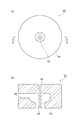
- FIG. 1 is a cross-sectional view perpendicular to the longitudinal direction of a hollow fiber-like carbon membrane 10 according to this embodiment. Since the carbon membrane 10 has a hollow fiber shape, the surface area per unit volume of the carbon membrane 10 is increased as compared with a flat carbon membrane, so that the hydrogen separation ability of the carbon membrane 10 is improved. Further, the hollow fiber-like carbon membrane 10 is excellent in pressure resistance, and is therefore suitable for gas phase separation by pressure difference. Further, the hollow fiber-like carbon membrane 10 is easy to process and has a large surface area per unit volume. Therefore, by using the hollow fiber-like carbon membrane 10, it is possible to manufacture a hydrogen separation module that is small and excellent in separation performance.
- the hydrogen separation module 30 includes an outer cylinder (chamber 32) and a plurality of hollow fiber-like carbon membranes 10 disposed in the chamber 32.
- the plurality of carbon films 10 are bundled.
- the inside of the chamber 32 and the inside of each carbon film 10 are substantially completely separated by each carbon film 10.
- the hydrogen gas obtained by the above dehydrogenation reaction is introduced into the chamber 32.
- the inside of each carbon film 10 is degassed and decompressed from one end of each carbon film 10 by a vacuum pump.
- the carbon film 10 has innumerable pores penetrating the carbon film 10 in the thickness direction.
- the pore diameter is small enough to allow only hydrogen molecules to permeate among molecules composed of a plurality of atoms.
- the carbon film 10 has a narrow pore size distribution showing a maximum value (a steep peak) in the vicinity of the molecular diameter (0.289 nm) of hydrogen molecules. Accordingly, driven by the pressure difference between the inside of the chamber 32 and the inside of the carbon film 10, hydrogen molecules in the chamber 32 move from the outside to the inside of the carbon film 10. On the other hand, the aromatic compound (AH) in the hydrogen gas in the chamber 32 cannot permeate each carbon film 10.
- the hydrogen gas that has moved to the inside of each carbon film 10 is compressed by a compressor and then used as fuel for the fuel cell.
- the aromatic compound separated from the hydrogen gas may be reused as an organic hydride by being recovered and hydrogenated. Even when the pressure inside the chamber 32 is adjusted to several pressures and the pressure inside each carbon film 10 is adjusted to atmospheric pressure, the pressure difference between the inside of the chamber 32 and the inside of the carbon film 10 is As a result, hydrogen molecules in the chamber 32 move from the outside to the inside of the carbon film 10.
- the aromatic compound may be liquid or solid at normal temperature (about 15 ° C.), and may be a monocyclic aromatic compound or a bicyclic aromatic compound.
- the aromatic compound at least one selected from the group consisting of benzene, toluene, xylene, ethylbenzene, tetralin, naphthalene, methylnaphthalene and ethylnaphthalene may be used.
- These aromatic compounds are organic hydride dehydrogenates.
- the carbon film 10 is used for separation of a gas phase (hydrogen gas containing an aromatic compound).
- a gas phase hydrogen gas containing an aromatic compound
- the molar transmittance of the hydrogen passing through the carbon film 10 is n H2.
- the temperature of the gas phase hydrogen gas containing an aromatic compound
- the molar transmittance of the aromatic compound that permeates the carbon film 10 is n AH .
- the temperature of the gas phase a mixed gas of hydrogen and nitrogen
- the molar transmittance of nitrogen passing through the carbon film 10 is n N2.
- the “temperature below the boiling point of the aromatic compound (evaluation temperature)” means a temperature of 110 ° C. or less or a temperature of 100 ° C. or less. (For example, 90 ° C.).
- the separation factor n H2 / n AH is 100,000 or more, and the separation factor n H2 / n N2 is 200 or more.
- the separation factors n H2 / n AH and n H2 / n N2 are each equal to or higher than the lower limit, the carbon membrane 10 exhibits excellent hydrogen separation ability and high purity suitable for a fuel cell (for example, 99.99 to 99.9999 mol%) of hydrogen gas can be purified.
- the carbon membrane 10 according to the present embodiment is excellent in hydrogen separation performance, according to the present embodiment, unlike a conventional hydrogen purification method using a separation membrane, a multi-stage hydrogen separation step is not performed. In any case, high-purity hydrogen gas can be obtained by a single-stage gas phase separation process.
- the separation ability of conventional inorganic membranes was easily lowered by acidic or basic compounds. Since conventional polymer membranes (organic membranes) are easily deteriorated by a gas containing an aromatic compound, it has been difficult to maintain the hydrogen separation ability of conventional polymer membranes over time. In conventional carbon membranes, the pore size distribution is wide, so that toluene is irreversibly adsorbed in the large pores or permeates through the large pores, resulting in a decrease in hydrogen separation ability over time. was there. On the other hand, the carbon membrane 10 according to this embodiment has high separation coefficients n H2 / n AH and n H2 / n N2 .
- the carbon film 10 has a narrow pore size distribution showing a maximum value in the vicinity of the molecular diameter of hydrogen molecules. Therefore, in this embodiment, the aromatic compound is difficult to be adsorbed in the pores of the carbon film 10 even if it is below the boiling point of the aromatic compound. Therefore, the hydrogen separation ability of the carbon membrane 10 according to the present embodiment is less likely to decrease with time even below the boiling point of the aromatic compound, compared to the conventional zeolite membrane, silica membrane, polymer membrane, and carbon membrane. Maintained at a high level.
- the separation coefficient n H2 / n AH is theoretically always 100,000 or more within the range below the boiling point of the aromatic compound (the hydrogen boiling point is ⁇ 252.6 ° C. or more).
- the separation coefficient n H2 / n N2 is also theoretically at least 200 within the range below the boiling point of the aromatic compound (at least the hydrogen boiling point of ⁇ 252.6 ° C.).
- the separation factor n H2 / n N2 at 30 ° C. is about 1000.
- carbon membrane separation factor n H2 / n N2 is 500 at 90 ° C.
- the carbon film 10 selectively transmits only hydrogen molecules among molecules composed of two or more atoms, and does not substantially transmit aromatic compound molecules. Therefore, n AH is as close to zero as possible, and the theoretical upper limit value of the separation coefficient n H2 / n AH is infinite.
- the detection limit of n AH at the present time (the lower limit of the number of moles of quantifiable aromatic compound) is about 10 mol ⁇ ppb
- separation factor n H2 / n AH based on the detection limit of the n AH is about It is about 1 ⁇ 10 9 . Therefore, n H2 / n AH may be 1 ⁇ 10 5 to 1 ⁇ 10 9 .
- the actual separation coefficient n H2 / n AH is larger than 1 ⁇ 10 9 .
- the lower limit value of n AH becomes smaller, so that the upper limit value of the separation coefficient n H2 / n AH becomes larger. For these reasons, it is difficult to define the upper limit value of the separation factor n H2 / n AH .
- the separation factor n H2 / n N2 may be 217 or more, 311 or more, 323 or more, or 500 or more. Further, the separation factor n H2 / n N2 may be 591 or less and may be 570 or less.
- the pore diameter of the carbon film 10 is controlled to be about the molecular diameter of hydrogen molecules, only hydrogen molecules permeate the carbon film 10 out of molecules composed of two or more atoms, and nitrogen molecules are substantially It does not permeate the carbon film 10. In this case, n N2 approaches zero as much as possible, and the theoretical upper limit value of the separation coefficient n H2 / n N2 diverges infinitely. Therefore, the upper limit value of the separation coefficient n H2 / n AH is not particularly limited.
- a separation factor nH2 / nN2 is It also has an meaning as an alternative indicator of hydrogen separation ability.
- the carbon film 10 has innumerable pores penetrating the carbon film 10 in the thickness direction.
- the separation factor n H2 / n AH of the carbon membrane 10 is 100000 or more because the pore diameter and the number of pores (or moles) are large enough to allow hydrogen molecules to permeate and smaller than the molecular diameter of the aromatic compound.
- the cumulative value of the product with the transmittance n H2 ) is at least about 100,000 times the cumulative value of the product of the pore diameter larger than the molecular diameter of the aromatic compound and the number of pores (or molar transmittance n AH ). It means that there is.
- the separation factor n H2 / n N2 of the carbon membrane 10 being 200 or more means that the pore diameter and the number of pores (or molar permeation) are large enough to allow hydrogen molecules to permeate and smaller than the molecular diameter of nitrogen molecules.
- the cumulative value of the product with the ratio n H2 ) is about 200 times or more the cumulative value of the product of the pore diameter larger than the molecular diameter of the nitrogen molecule and the number of pores (or molar permeability n N2 ). Means.
- the separation factors n H2 / n AH and n H 2 / n AH reflect the pore size distribution in the carbon membrane 10.
- n H2 / n AH is 100,000 or more and n H2 / n N2 is 200 or more means that the number of pores small enough to selectively permeate only hydrogen molecules in the carbon film 10 is remarkably high. It represents a lot. That is, the pore size distribution of the carbon film 10 is narrow, and shows a maximum value (a steep peak) in the vicinity of the molecular diameter (0.289 nm) of hydrogen molecules. In other words, n H2 / n AH is 100,000 or more and n H2 / n N2 is 200 or more.
- the range of the pore diameter of the carbon film 10 may be large enough to permeate hydrogen molecules and smaller than the molecular diameter of the aromatic compound. Therefore, the pore diameter range of the carbon film 10 may be, for example, 0.3 to 0.5 nm.
- the molar transmittance (number of moles) of each molecule in the carbon film 10 is measured.
- the upper and lower limit values of the molecular diameter of the molecule that is equal to or greater than the detection limit value substantially correspond to the upper and lower limit values of the pore diameter of the carbon membrane 10.
- the average value of the pore diameter of the carbon film 10 may be 0.2 to 0.4 nm, or 0.25 to 0.35 nm.
- the average value of the pore diameter is, for example, a weighted average of the molecular diameter of each molecule based on the measured value of the molar transmittance of each molecule.
- the pore size distribution, pore volume ratio, specific surface area and the like of the pores of the gas separation membrane are measured by an adsorption method using a gas such as carbon dioxide (or nitrogen).
- a gas such as carbon dioxide (or nitrogen).
- the carbon film 10 according to this embodiment substantially transmits only hydrogen molecules and does not transmit atoms and molecules larger than the hydrogen molecules. Accordingly, it is difficult for carbon dioxide molecules having a molecular diameter of 0.33 nm (or nitrogen molecules having a molecular diameter of 0.364 nm) to enter the pores of the carbon film 10. Therefore, unlike the case of the conventional gas separation membrane, it is difficult to specify the pore size distribution, the pore volume ratio, and the specific surface area of the carbon membrane 10 according to the present embodiment by the conventional adsorption method.
- n H2 / n AH may be measured using a pure hydrogen gas and a pure gas of an aromatic compound, respectively, or may be measured using a mixed gas of hydrogen and an aromatic compound. Good.
- n H2 and n N2 may be measured using a pure hydrogen gas and a pure nitrogen gas, respectively, or may be measured using a mixed gas of hydrogen and nitrogen.
- the composition of the mixed gas of hydrogen and nitrogen is not particularly limited.
- the hydrogen content in the mixed gas may be 90 mol% or more.
- the thickness of the carbon film 10 may be 0.1 to 50 ⁇ m, or 5 to 20 ⁇ m. As a result, sufficient mechanical strength of the carbon membrane 10 and excellent hydrogen separation ability can be easily achieved.
- the thickness of the carbon membrane 10 is the thickness of the separation active layer, and the separation active layer means a portion that contributes to hydrogen separation in the carbon membrane 10.
- the raw material of the hollow fiber-like carbon membrane 10 is a poly (2,6-dimethyl-1,4-phenylene oxide) derivative (hereinafter referred to as the case where the structural unit is represented by the following general formulas (a) and (b)). "Sulfonated PPO").
- R 11 and R 12 each independently represent hydrogen, —SO 3 H, or —SO 3 NH 4 . However, when R 11 is hydrogen, R 12 is other than hydrogen, and when R 12 is hydrogen, R 11 is other than hydrogen. ]
- the content A of the structural unit represented by (b) in the sulfonated PPO may be 15 to 60 mol% with respect to the total amount of the structural units (a) and (b).
- the molecular weight of the sulfonated PPO is not limited as long as the carbonized film can be produced, but the weight average molecular weight of the sulfonated PPO may be 5000 to 1000000.
- FIG. 3a and 3b show a molding device 20 for forming a hollow fiber-like carbon membrane 10.
- FIG. The forming apparatus 20 includes a spinning nozzle outer tube 24 and a spinning nozzle inner tube 22 disposed inside the spinning nozzle outer tube 24.
- a core liquid inlet 26 is formed at one end of the spinning nozzle inner tube 22.
- the film-forming stock solution is supplied from the film-forming stock solution inlet 28 and is pushed out from the gap between the spinning nozzle inner tube 22 and the spinning nozzle outer tube 24. By adjusting the gap, the thickness of the obtained carbon film 10 is controlled.
- the above sulfonated PPO is dissolved in an arbitrary solvent to prepare a film forming stock solution.
- a substance that stabilizes the film-forming stock solution may be added to the film-forming stock solution.
- the solvent include methanol, ethanol, tetrahydrofuran, N, N-dimethylacetamide, N-methyl-2-pyrrolidone and the like. A mixture of these solvents may be used.
- the film-forming stock solution is extruded through the gap between the spinning nozzle inner tube 22 and the spinning nozzle outer tube 24, thereby producing a hollow fiber shaped molded body. Then, the molded body is solidified in a coagulation bath. At this time, the outer diameter of the hollow fiber-shaped molded body can be controlled by appropriately adjusting the ratio of the diameter of the spinning nozzle outer tube 24 and the winding speed of the molded body.
- the core solution and the coagulation bath are mixed with the solvent of the film forming stock solution in the above process.
- the core liquid and the coagulation bath may be a solvent that is insoluble in the sulfonated PPO.
- a solvent may be water or an aqueous ammonium salt solution.
- ammonium salts include ammonium nitrate, ammonium hydrochloride, and ammonium sulfate.
- the temperature of the core liquid and coagulation bath may be ⁇ 20 to 60 ° C., or 0 to 30 ° C.
- the hollow fiber-shaped molded body is dried to obtain a hollow fiber-shaped polymer film that is a precursor of the carbon film 10.
- the polymer film is heated at a temperature lower than the temperature required for carbonization. This heating is called infusibilization treatment.
- Infusibilization means a crosslinking reaction in the polymer film.
- the infusibilization treatment may be performed in an air atmosphere.
- the heating rate of the atmosphere in the infusibilization treatment may be 1 to 20 ° C./min.
- the temperature of the atmosphere (heating temperature) in the infusibilization treatment may be 260 to 300 ° C.
- the time for maintaining this heating temperature (heating time) may be 30 to 180 minutes.
- Carbonization is performed on the infusible polymer film.
- a carbon fiber 10 having a hollow fiber shape is obtained by the carbonization treatment.
- the polymer film is accommodated in a decompressed container, and the polymer film is heated and carbonized in the container.
- the pressure of the container may be about 10 Pa or less.
- the atmosphere in the container may be replaced with an inert gas such as helium, argon, or nitrogen. In this case, the polymer film is heated and carbonized in an inert gas.
- the temperature rising rate of the atmosphere in the container for carbonization may be 1 to 20 ° C./min.
- the temperature (firing temperature) of the atmosphere in the container for performing the carbonization treatment is 620 to 750 ° C.
- the time for maintaining this firing temperature (firing time) may be 30 to 180 minutes.
- the carbon content in the carbon film 10 can be controlled by adjusting various conditions of the carbonization treatment.
- the carbon content in the carbon film 10 may be 85 atomic% or more and 100 atomic% or less.
- There may be a portion not carbonized in the carbon film 10 (a portion having the same composition as the polymer film, or a portion in which hydrogen or heteroatoms remain).
- the portion that is not carbonized imparts flexibility to the carbon film 10 and makes it difficult for the carbon film 10 to break.
- an aromatic compound having a large molecular structure such as toluene spreads the pores of the carbon film 10 in the non-carbonized part and permeates the carbon film 10. It becomes easy to do.
- the pore diameter of the carbon film 10 varies depending on the degree of carbonization of the polymer film (the degree of film shrinkage accompanying carbonization). Therefore, by adjusting various conditions of the carbonization treatment, the pore size and pore size distribution of the carbon membrane 10 can be controlled, and excellent hydrogen separation performance can be realized.
- the obtained carbon film 10 may be heated in the range of 150 to 300 ° C. for 30 minutes to 4 hours. By this post-treatment, flexibility can be imparted to the carbon membrane 10 while maintaining the hydrogen separation ability of the carbon membrane 10.
- Example 1 ⁇ Synthesis of sulfonated PPO> A solution 1 of poly (2,6-dimethyl-1,4-phenylene oxide) was prepared by dissolving 25.0 g of poly (2,6-dimethyl-1,4-phenylene oxide) in 600 ml of chloroform. Further, 15.5 ml of chlorosulfuric acid was dissolved in 80 ml of chloroform to prepare solution 2. Solution 1 to which solution 2 was added dropwise was reacted at room temperature for 30 minutes to obtain sulfonated PPO. The content A of the structural unit (b) in the obtained sulfonated PPO was 30 mol%.
- a polymer film which is a precursor of a carbon film, was obtained by the following method using the molding apparatus 20 shown in FIGS. 3a and 3b.
- the inner diameter of the spinning nozzle outer tube 24 was 0.5 mm, and the outer diameter of the spinning nozzle inner tube 22 was 0.35 mm.
- the core liquid is extruded from the spinning nozzle inner tube 22 and at the same time, the above-mentioned film forming raw solution is extruded into the coagulation bath (water) through the gap between the spinning nozzle inner tube 22 and the spinning nozzle outer tube 24, thereby forming a hollow fiber shaped molded body.
- the molded body was air-dried at room temperature or lower to obtain a polymer film.
- the polymer film was infusible by the following procedure. First, the polymer film was placed in a muffle furnace filled with air. Next, the temperature of the air atmosphere in the muffle furnace was increased to 290 ° C. at a rate of temperature increase of 8 ° C./min, and the temperature of the air atmosphere was maintained at 290 ° C. for 1 hour, and then the inside of the furnace was allowed to cool.
- the polymer membrane was carbonized by the following procedure.
- Example 2 A hollow fiber carbon membrane 10b was obtained in the same manner as in Example 1 except that the temperature in the vacuum electric furnace was maintained at 700 ° C. for 1 hour in the carbonization treatment.
- Example 1 A hollow fiber-like carbon membrane 10c was obtained in the same manner as in Example 1 except that the temperature in the vacuum electric furnace was maintained at 600 ° C. for 1 hour in the carbonization treatment.
- the flow rate of the mixed gas supplied into the chamber 32 was adjusted to about 100 times the gas permeation flow rate.
- concentrations (molar fractions) of H 2 and N 2 in the permeated gas were measured by gas chromatography of the above measuring apparatus. From the product of the gas permeation flow rate and the molar fraction of H 2 in the permeation gas, the H 2 permeation flow rate was calculated.
- the N 2 permeation flow rate was calculated from the product of the gas permeation flow rate and the mole fraction of N 2 in the permeation gas.
- the temperature of the test gas 1 was adjusted to 30 ° C.
- Test 1a the H 2 permeation flow rate and the N 2 permeation flow rate were measured at the beginning of the test.
- Test 1b In the test 1b, the temperature of the test gas 1 was adjusted to 90 ° C. In Test 1b, the H 2 permeation flow rate and the N 2 permeation flow rate were measured at two points in time at the beginning of the test and 800 hours after the start of the test. Except for these matters, Test 1b was carried out in the same manner as Test 1a.
- Test gas 2 mixtureed gas of toluene and H 2
- concentration of toluene was adjusted to 0.35 to 0.58 mol%.
- test gas 2 was used instead of test gas 1
- the flow rate (gas permeation amount) of the gas (permeated gas) permeated inside the carbon film 10a was measured by the same method as in test 1b.
- concentrations (molar fractions) of H 2 and toluene in the permeated gas were measured by gas chromatography of the above measuring apparatus.
- the H 2 permeation flow rate was determined. From the product of the gas permeation flow rate and the mole fraction of toluene in the permeation gas, the toluene permeation flow rate was determined.
- Test 2 the temperature of the test gas 2 was adjusted to 90 ° C.
- Test 2 the permeate flow rate of H 2 and the permeate flow rate of toluene were measured at two points in time at the beginning of the test and 800 hours after the start of the test. The toluene permeation flow rate after 800 hours from the start of the test was smaller than the detection limit value.
- boiling point of toluene was 111 ° C.
- the temperature of the test gas 1 in the tests 1a and 1b and the temperature of the test gas 2 in the test 2 were both lower than the boiling point of toluene.
- the transmittance Q of the gas component of interest is defined by the following formula 1.
- Q ⁇ permeation flow rate of gas component of interest (cm 3 ⁇ STP) ⁇ ⁇ ⁇ area (cm 2 ) ⁇ time (seconds) ⁇ partial pressure difference (cmHg) ⁇ (1)
- the target gas component means any one gas of H 2 , N 2 , and toluene (aromatic compound).
- the area is the total area of the carbon membrane 10a included in the hydrogen separation module 30.
- the time is the time during which the gas is allowed to pass through the carbon film 10a.
- the partial pressure difference is a difference between the partial pressure of the gas component of interest inside the chamber 32 and the partial pressure of the gas component of interest inside the carbon film 10a.
- the N 2 permeability Q N2 in the carbon film 10a at each measurement time point is obtained based on each value of the N 2 permeation flow rate measured at each measurement time point in the tests 1a and 1b. It was.
- the separation coefficient Q H2 / Q N2 of the carbon membrane 10a at each measurement time in the tests 1a and 1b was determined.
- Q H2 and Q N2 are based on the permeate flow rate of H 2 and the permeate flow rate of N 2 measured under the same pressure and temperature conditions. Therefore, the separation factor Q H2 / Q N2 is equal to the separation factor n H2 / n N2 expressed by the molar transmittance ratio.
- the separation factor Q H2 / Q N2 is referred to as n H2 / n N2 .
- Table 1 below shows the separation coefficient n H2 / n N2 of the carbon membrane 10 a at each measurement time of the tests 1a and 1b.
- the separation factor Q H2 / Q AH of the carbon membrane 10 a at each measurement time point in Test 2 was determined.
- Q H2 and Q AH are based on the permeate flow rate of H 2 and the permeate flow rate of toluene measured under the same pressure and temperature conditions. Therefore, the separation factor Q H2 / Q AH is equal to n H2 / n AH expressed in molar ratio.
- the separation factor Q H2 / Q AH is denoted as n H2 / n AH .
- Table 1 below shows the separation factor n H2 / n AH of the carbon membrane 10 a at each measurement time point in Test 2 above.
- a hydrogen separation module 30 shown in FIGS. 2a and 2b was produced using the carbon membrane 10b instead of the carbon membrane 10a.
- Tests 1a, 1b, and 2 using the carbon film 10b were performed in the same manner as in Example 1.
- transmission flow rate of toluene at the time of 800 hours after the start of the test 2 using the carbon film 10b was smaller than a detection limit value.
- the separation coefficient n H2 / n N2 of the carbon membrane 10 b at each measurement time of the tests 1 a and 1 b was obtained.
- a hydrogen separation module 30 shown in FIGS. 2a and 2b was produced using the carbon membrane 10c instead of the carbon membrane 10a.
- Tests 1a, 1b, and 2 using the carbon film 10c were performed in the same manner as in Example 1.
- the separation coefficient n H2 / n N2 of the carbon membrane 10 c at each measurement time of the tests 1 a and 1 b was obtained.
- the separation coefficient n H2 / n AH of the carbon membrane 10 c at each measurement time in Test 2 was obtained.
- Table 1 below shows the separation coefficient n H2 / n N2 of the carbon membrane 10 c at each measurement time of the tests 1a and 1b.
- Table 1 below shows the separation coefficient n H2 / n AH of the carbon membrane 10 c at each measurement time point in Test 2.
- Example 3 In the same manner as in Example 1 except that the upper limit value of the pore diameter of the carbon film was controlled to be close to the molecular diameter of toluene (0.585 nm) by adjusting various conditions of infusibilization treatment and carbonization treatment.
- a carbon film 10d of Example 3 was produced.
- a hydrogen separation module 30 shown in FIGS. 2a and 2b was produced using the carbon membrane 10d instead of the carbon membrane 10a.
- the following gas permeation flow rates in the carbon membrane 10d were measured. The temperature of each gas at the time of measurement was adjusted to 90 ° C.
- the carbon membrane according to the present invention is suitable for refining hydrogen gas used as fuel for fuel cells.
Landscapes
- Chemical & Material Sciences (AREA)
- Chemical Kinetics & Catalysis (AREA)
- Inorganic Chemistry (AREA)
- Engineering & Computer Science (AREA)
- Organic Chemistry (AREA)
- Manufacturing & Machinery (AREA)
- Combustion & Propulsion (AREA)
- General Health & Medical Sciences (AREA)
- Health & Medical Sciences (AREA)
- Life Sciences & Earth Sciences (AREA)
- Sustainable Development (AREA)
- Sustainable Energy (AREA)
- Electrochemistry (AREA)
- General Chemical & Material Sciences (AREA)
- Separation Using Semi-Permeable Membranes (AREA)
- Hydrogen, Water And Hydrids (AREA)
- Carbon And Carbon Compounds (AREA)
Abstract
水素の分離能に優れ、且つ水素の分離能が経時的に低下し難い炭素膜を提供する。本発明に係る炭素膜の一態様は、芳香族化合物を含む水素ガス、又は窒素を含む水素ガスを透過させて、水素ガスを精製する炭素膜10であって、芳香族化合物の沸点以下の温度において炭素膜を透過した水素、芳香族化合物及び窒素のモル透過率がそれぞれnH2、nAH及びnN2であるとき、芳香族化合物の沸点以下の温度における分離係数nH2/nAHが100000以上であり、芳香族化合物の沸点以下の温度における分離係数nH2/nN2が200以上である。
Description
本発明は、炭素膜及び炭素膜の製造方法に関する。
炭素膜は、種々の無機膜の中でも優れた気体分離能を示し、有機膜では達成困難な耐熱性・耐薬品性が要求される環境でも使用できることから、炭素膜の実用化が期待されている。特に、中空糸状の炭素膜は、耐圧性に優れ、かつ単位容積あたりに占める膜面積が大きい。したがって、中空糸状の炭素膜によれば、平膜やスパイラル膜に比べてコンパクトな水素分離モジュールの製作が可能である。
これまでに、柔軟性があり、曲げ強度に優れた炭素膜として、セルロース系炭素膜が知られている(下記特許文献1参照)。また、芳香族ポリイミドからなる非対称性中空糸膜を部分的に炭化して得られる炭素膜が報告されている(下記特許文献2参照)。さらに、破損しにくい柔軟性に優れ、かつ分離能に優れた、ポリフェニレンオキシド誘導体からなる中空糸炭素膜も知られている(下記特許文献3参照)。
燃料電池用の燃料として用いられる水素ガスの製造では、有機ハイドライドの脱水素化によって水素ガスと芳香族化合物とを生成させる。この水素ガスを燃料電池用の燃料として用いるためには、さらなる水素ガスの精製により、水素ガスから芳香族化合物を除去する必要がある。なぜなら、燃料電池用の燃料として用いる水素ガスには、極めて高い純度(例えば99.99~99.9999mol%)が要求されるからである。本発明者らは、水素ガスの精製に炭素膜を用いる研究を行った。しかしながら、本発明者らの研究の結果、従来の炭素膜の水素の分離能は十分ではなく、経時的に低下し易いため、燃料電池に利用可能な高純度の水素ガスを従来の炭素膜を用いて精製することは困難であることが判明した。
本発明は、このような実情に鑑みてなされたものであり、水素の分離能に優れ、且つ水素の分離能が経時的に低下し難い炭素膜及び当該炭素膜の製造方法を提供することを目的とする。
本発明に係る炭素膜の一態様は、芳香族化合物を含む水素ガス、又は窒素を含む水素ガスを透過させて、水素ガスを精製する炭素膜であって、芳香族化合物の沸点以下の温度において炭素膜を透過する水素のモル透過率がnH2であり、芳香族化合物の沸点以下の温度において炭素膜を透過する芳香族化合物のモル透過率がnAHであり、芳香族化合物の沸点以下の温度において炭素膜を透過する窒素のモル透過率がnN2であるとき、芳香族化合物の沸点以下の温度(評価温度)における分離係数nH2/nAHが100000以上であり、芳香族化合物の沸点以下の温度(評価温度)における分離係数nH2/nN2が200以上である。
炭素膜は中空糸状(管状)であってよい。
芳香族化合物は、ベンゼン、トルエン、キシレン、エチルベンゼン、テトラリン、ナフタレン、メチルナフタレン及びエチルナフタレンからなる群より選ばれる少なくとも一種であればよい。
本発明に係る炭素膜の製造方法の一態様は、下記一般式(a)及び(b)で表される構成単位からなるポリ(2,6-ジメチル-1,4-フェニレンオキシド)誘導体を溶媒に溶かして、製膜原液を調製する工程と、製膜原液から高分子膜を得る工程と、高分子膜の不融化処理を行う工程と、不融化処理後の高分子膜の炭化処理を620~750℃で行う工程と、を備える。


[上記一般式中、R11及びR12は、各々独立して、水素、-SO3H、又は-SO3NH4を示す。ただし、R11が水素であるとき、R12は水素以外のものであり、R12が水素であるとき、R11は水素以外のものである。]
本発明に係る炭素膜の一態様は、上記炭素膜の製造方法によって製造されるものであってよい。
本発明によれば、水素の分離能に優れ、且つ水素の分離能が経時的に低下し難い炭素膜及び当該炭素膜の製造方法を提供することができる。
以下、本発明の好適な実施形態について詳細に説明する。ただし、本発明は下記実施形態に限られるものではない。
(炭素膜)
本実施形態に係る炭素膜は、燃料電池用の燃料として用いられる水素ガスの精製に用いる分離膜である。燃料電池用の水素ガスの製造では、有機ハイドライドの脱水素化によって、水素ガスと芳香族化合物とを生成させる。水素ガスと芳香族化合物とは、常温(15℃)において、気相(水素ガス)と液相(芳香族化合物)とに分離される。しかし、気相(水素ガス)中には微量の芳香族化合物の蒸気が存在する。気相における芳香族化合物の分圧の上限値は、芳香族化合物の飽和蒸気圧程度である。燃料電池用の水素ガスには高い純度が求められる。したがって、以下に説明するように、水素ガス中に残存する芳香族化合物を、本実施形態に係る炭素膜によって除去する。
本実施形態に係る炭素膜は、燃料電池用の燃料として用いられる水素ガスの精製に用いる分離膜である。燃料電池用の水素ガスの製造では、有機ハイドライドの脱水素化によって、水素ガスと芳香族化合物とを生成させる。水素ガスと芳香族化合物とは、常温(15℃)において、気相(水素ガス)と液相(芳香族化合物)とに分離される。しかし、気相(水素ガス)中には微量の芳香族化合物の蒸気が存在する。気相における芳香族化合物の分圧の上限値は、芳香族化合物の飽和蒸気圧程度である。燃料電池用の水素ガスには高い純度が求められる。したがって、以下に説明するように、水素ガス中に残存する芳香族化合物を、本実施形態に係る炭素膜によって除去する。
有機ハイドライドとしては、例えば、シクロヘキサン、メチルシクロヘキサン、ジメチルシクロヘキサン、デカリン、1-メチルデカリン、2-メチルデカリン及び2-エチルデカリンからなる群より選ばれる一種又は複数種を用いればよい。
図1は、本実施形態に係る中空糸状の炭素膜10の長手方向に垂直な断面図である。炭素膜10が中空糸状であることにより、炭素膜10の単位容積当たりの表面積が、平坦な炭素膜に比べて増加するため、炭素膜10の水素の分離能が向上する。また、中空糸状の炭素膜10は耐圧性に優れるので、圧力差による気相の分離に適している。さらに、中空糸状の炭素膜10は加工しやすく、その単位容積当たりの表面積が大きい。したがって、中空糸状の炭素膜10を用いることにより、小型で分離能に優れた水素分離モジュールを製造することが可能となる。
図2a及び図2bに、本実施形態に係る炭素膜10を具備する水素分離モジュール30を示す。水素分離モジュール30は、外筒(チャンバー32)と、チャンバー32内に配置された複数の中空糸状の炭素膜10と、を備える。複数の炭素膜10は束ねられている。チャンバー32の内部と各炭素膜10の内側とは、各炭素膜10によって略完全に隔てられている。上記の脱水素化反応によって得られた水素ガスは、チャンバー32の内部に導入される。各炭素膜10の内側は、各炭素膜10の一方の端部から、真空ポンプによって脱気され、減圧される。炭素膜10には、炭素膜10を厚さ方向に貫通する無数の細孔が形成されている。その細孔径は、複数の原子からなる分子のうち水素分子のみを透過させる程度に小さい。そして、炭素膜10は水素分子の分子径(0.289nm)近傍で極大値(急峻なピーク)を示す狭小な細孔径の分布を有する。したがって、チャンバー32の内部と炭素膜10の内側との気圧差で駆動されて、チャンバー32内の水素分子は炭素膜10の外側から内側へ移動する。一方、チャンバー32内の水素ガス中の芳香族化合物(AH)は各炭素膜10を透過することができない。各炭素膜10の内側に移動した水素ガスは、コンプレッサーで圧縮された後、燃料電池用の燃料として用いられる。水素ガスから分離された芳香族化合物は、回収され、水素化されることにより、有機ハイドライドとして再利用されてもよい。なお、チャンバー32の内部の気圧を数気圧に調整し、各炭素膜10の内側の気圧を大気圧に調整した場合であっても、チャンバー32の内部と炭素膜10の内側との気圧差が生じるため、チャンバー32内の水素分子は炭素膜10の外側から内側へ移動する。
芳香族化合物は、常温(約15℃)において、液体又は固体であればよく、単環式の芳香族化合物又は二環式の芳香族化合物であればよい。芳香族化合物としては、ベンゼン、トルエン、キシレン、エチルベンゼン、テトラリン、ナフタレン、メチルナフタレン及びエチルナフタレンからなる群より選ばれる少なくとも一種を用いればよい。これら芳香族化合物は、有機ハイドライドの脱水素化物である。
上記のように、炭素膜10は気相(芳香族化合物を含む水素ガス)の分離に用いられる。本実施形態において、気相の温度が芳香族化合物の沸点以下であるとき、炭素膜10を透過する水素のモル透過率はnH2である。気相(芳香族化合物を含む水素ガス)の温度が芳香族化合物の沸点以下であるとき、炭素膜10を透過する芳香族化合物のモル透過率はnAHである。気相(水素と窒素の混合ガス)の温度が芳香族化合物の沸点以下であるとき、炭素膜10を透過する窒素のモル透過率はnN2である。なお、芳香族化合物がトルエンである場合、トルエンの沸点は約110℃であるので、「芳香族化合物の沸点以下の温度(評価温度)」とは、110℃以下の温度又は100℃以下の温度(例えば90℃)である。
本実施形態では、分離係数nH2/nAHが100000以上であり、分離係数nH2/nN2が200以上である。分離係数nH2/nAH及びnH2/nN2がそれぞれ上記下限値以上であることにより、炭素膜10は優れた水素の分離能を示し、燃料電池に適した高純度(例えば99.99~99.9999mol%)の水素ガスを精製することが可能となる。
本実施形態に係る炭素膜10は水素の分離能に優れるので、本実施形態によれば、従来の分離膜を用いた水素の精製方法とは異なり、多段階の水素の分離工程を実施しなくとも、一段階の気相分離工程によって高純度の水素ガスを得ることが可能である。
ゼオライト膜又はシリカ膜等の従来の無機膜では、その製造の過程で欠陥を低減することが容易ではないため、細孔径及びその分布を制御して高純度の水素ガスを得ることが困難であった。また、ゼオライト膜又はシリカ膜等の従来の無機膜を用いて芳香族化合物の沸点以下で水素の分離を行った場合、無機膜の表面(細孔表面)に芳香族化合物が吸着して無機膜の細孔を塞ぎ、無機膜の分離能が低下する。したがって、従来は、芳香族化合物を無機膜から脱着させるために、芳香族化合物の沸点より高い温度で水素の分離を行わなければならなかった。さらに、従来の無機膜の分離能は、酸性又は塩基性の化合物によって低下し易かった。従来の高分子膜(有機膜)は、芳香族化合物を含むガスによって劣化し易いため、従来の高分子膜の水素の分離能を経時的に維持することは困難であった。従来の炭素膜では、その細孔径の分布が広いため、トルエンが大きな細孔内に不可逆的に吸着したり、大きな細孔を透過したりして、水素の分離能が経時的に低下することがあった。一方、本実施形態に係る炭素膜10は、高い分離係数nH2/nAH及びnH2/nN2を有する。これは炭素膜10が水素分子の分子径近傍で極大値を示す狭小な細孔径の分布を有することを意味する。したがって、本実施形態では、芳香族化合物の沸点以下であっても、芳香族化合物が炭素膜10の細孔内に吸着し難い。したがって、本実施形態に係る炭素膜10の水素の分離能は、従来のゼオライト膜、シリカ膜、高分子膜及び炭素膜に比べて、芳香族化合物の沸点以下においても経時的に低下し難く、高い水準に維持される。
分離係数は、理論的に、分離される気相の温度が高いほど小さくなり、気相の温度が低いほど高くなる。したがって、分離係数nH2/nAHは、理論的に、芳香族化合物の沸点以下(水素の沸点である-252.6℃以上)の範囲において、必ず100000以上であり、温度の低下に伴って増加する。また、分離係数nH2/nN2も、理論的に、芳香族化合物の沸点以下(水素の沸点である-252.6℃以上)の範囲において、必ず200以上であり、温度の低下に伴って増加する。例えば、90℃における分離係数nH2/nN2が300程度である炭素膜の場合、30℃における分離係数nH2/nN2は約1000である。90℃における分離係数nH2/nN2が500である炭素膜の場合、30℃における分離係数nH2/nN2は約1300である。
炭素膜10は、2つ以上の原子から構成される分子のうち、水素分子のみを選択的に透過させ、芳香族化合物の分子を実質的に透過させない。したがって、nAHは限りなくゼロに近く、分離係数nH2/nAHの理論的な上限値は無限大である。ただし、現時点におけるnAHの検出限界値(定量可能な芳香族化合物のモル数の下限値)は10mol・ppb程度であり、このnAHの検出限界値に基づく分離係数nH2/nAHは約1×109程度である。したがって、nH2/nAHは1×105~1×109であってもよい。ただし、実際に炭素膜10を透過する芳香族化合物のモル数は検出限界値よりも小さいので、実際の分離係数nH2/nAHは1×109よりも大きい。また、芳香族化合物の検出精度の向上に伴い、nAHの下限値は小さくなるので、分離係数nH2/nAHの上限値は大きくなる。これらの理由から、分離係数nH2/nAHの上限値を規定することは困難である。
分離係数nH2/nN2は、217以上であってもよく、311以上であってもよく、323以上であってもよく、500以上であってもよい。また、分離係数nH2/nN2は、591以下であってよく、570以下であってもよい。なお、炭素膜10の細孔径を水素分子の分子径程度に制御した場合、2つ以上の原子から構成される分子のうち、水素分子のみが炭素膜10を透過し、窒素分子は実質的に炭素膜10を透過しない。この場合、nN2は限りなくゼロに近づき、分離係数nH2/nN2の理論的な上限値は無限大に発散する。そのため、分離係数nH2/nAHの上限値は特に限定されない。なお、炭素膜10における芳香族化合物の透過量が検出限界値を下回るほど著しく少なく、分離係数nH2/nAHが無限大に発散する場合には、分離係数nH2/nN2は炭素膜の水素の分離能を示す代替的指標としての意味も有する。
炭素膜10には、上記の通り、炭素膜10を厚さ方向に貫通する無数の細孔が形成されている。そして、炭素膜10の分離係数nH2/nAHが100000以上であることは、水素分子を透過させる程度に大きく且つ芳香族化合物の分子径よりも小さい細孔の孔径とその孔数(又はモル透過率nH2)との積の累積値が、芳香族化合物の分子径よりも大きい細孔の孔径とその孔数(又はモル透過率nAH)との積の累積値の約100000倍以上であることを意味する。また、炭素膜10の分離係数nH2/nN2が200以上であることは、水素分子を透過させる程度に大きく且つ窒素分子の分子径よりも小さい細孔の孔径とその孔数(又はモル透過率nH2)との積の累積値が、窒素分子の分子径よりも大きい細孔の孔径とその孔数(又はモル透過率nN2)との積の累積値の約200倍以上であることを意味する。このように、分離係数nH2/nAH及びnH2/nAHは、炭素膜10における細孔径の分布を反映している。そして、nH2/nAHが100000以上であり、且つnH2/nN2が200以上であることは、炭素膜10において、水素分子のみを選択的に透過させる程度に小さい細孔の数が著しく多いことを表している。つまり、炭素膜10の細孔径の分布は狭小であり、水素分子の分子径(0.289nm)近傍で極大値(急峻なピーク)を示す。換言すれば、nH2/nAHが100000以上であり、且つnH2/nN2が200以上であることは、炭素膜10が、気相中の分子をその分子径に応じて篩い分け、水素分子のみを選択的に透過させる機能を有することを意味する。
炭素膜10の細孔径の範囲は、水素分子を透過させる程度に大きく、且つ芳香族化合物の分子径よりも小さければよい。したがって、炭素膜10の細孔径の範囲は、例えば0.3~0.5nmであればよい。下記のような分子径の異なる複数の分子を用いて、炭素膜10における各分子のモル透過率(炭素膜10を透過した分子のモル数)を測定したとき、モル透過率(モル数)が検出限界値以上である分子の分子径の上下限値が、炭素膜10の細孔径の上下限値にほぼ対応する。なお、本発明者らは、このような測定により、炭素膜10の細孔径が上記数値範囲内にあることを確認した。炭素膜10の細孔径の平均値は、0.2~0.4nm、又は0.25~0.35nmであってよい。なお、細孔径の平均値とは、例えば、各分子のモル透過率の測定値に基づく各分子の分子径の加重平均である。
He(単原子分子径:0.26nm)
H2(分子径:0.289nm)
CO2(分子径:0.33nm)
O2(分子径:0.346nm)
N2(分子径:0.364nm)
CH4(分子径:0.38nm)
トルエン(分子径:0.585nm)
He(単原子分子径:0.26nm)
H2(分子径:0.289nm)
CO2(分子径:0.33nm)
O2(分子径:0.346nm)
N2(分子径:0.364nm)
CH4(分子径:0.38nm)
トルエン(分子径:0.585nm)
一般に、気体分離膜の細孔の孔径分布、細孔容積率及び比表面積等は、二酸化炭素(又は窒素)等のガスを用いた吸着法によって測定される。しかし、本実施形態に係る炭素膜10は、実質的に水素分子のみを透過させ、水素分子よりも大きい原子及び分子を透過させない。したがって、分子径が0.33nmである二酸化炭素分子(又は分子径が0.364nmである窒素分子)は炭素膜10の細孔に侵入することが困難である。したがって、従来の気体分離膜の場合とは異なり、本実施形態に係る炭素膜10の孔径分布、細孔容積率及び比表面積を、従来の吸着法によって特定することは困難である。また、二酸化炭素を用いた吸着法で評価される細孔は、必ずしも水素の透過に寄与する細孔(貫通孔)を反映するわけではない。したがって、本実施形態の炭素膜10において水素の透過に寄与する細孔に係る特徴を、上記の分離係数nH2/nAH及びnH2/nN2以外の物性値を用いて特定することは困難である。なお、nH2及びnAHの各値は、水素の純ガス及び芳香族化合物の純ガスをそれぞれ単独で用いて測定してもよく、水素及び芳香族化合物の混合ガスを用いて測定してもよい。またnH2及びnN2の各値は、水素の純ガス及び窒素の純ガスをそれぞれ単独で用いて測定してもよく、水素及び窒素の混合ガスを用いて測定してもよい。水素及び窒素の混合ガスの組成は特に限定されないが、例えば、混合ガスにおける水素の含有率は90mol%以上であればよい。
炭素膜10の厚みは、0.1~50μm、又は5~20μmであってよい。これにより炭素膜10の十分な機械的強度と優れた水素の分離能とが両立し易くなる。なお、炭素膜10の厚みとは分離活性層の厚みであり、分離活性層とは炭素膜10において水素の分離に寄与する部分を意味する。
(炭素膜の製造方法)
中空糸状の炭素膜10の原料は、下記一般式(a)及び(b)で表される構成単位からなるポリ(2,6-ジメチル-1,4-フェニレンオキシド)誘導体(以下、場合により、「スルホン化PPO」という。)である。
中空糸状の炭素膜10の原料は、下記一般式(a)及び(b)で表される構成単位からなるポリ(2,6-ジメチル-1,4-フェニレンオキシド)誘導体(以下、場合により、「スルホン化PPO」という。)である。


上記スルホン化PPOにおける(b)で表される構成単位の含有量Aは、構成単位(a)及び(b)の合計量に対して、15~60モル%であってよい。
上記スルホン化PPOの分子量は、炭化膜を作製できる大きさであれば制限されないが、スルホン化PPOの重量平均分子量は、5000~1000000であってよい。
図3a及び図3bは、中空糸状の炭素膜10の成形装置20を示す。成形装置20は、紡糸ノズル外管24と、紡糸ノズル外管24の内側に配置された紡糸ノズル内管22と、を備える。紡糸ノズル内管22の一方の端部には、芯液の導入口26が形成されている。製膜原液は、製膜原液の導入口28から供給され、紡糸ノズル内管22と紡糸ノズル外管24と隙間から押し出される。この隙間の調整により、得られる炭素膜10の厚さが制御される。
上記スルホン化PPOを任意の溶媒に溶かし、製膜原液を調製する。製膜原液を安定させる物質等を製膜原液に添加してもよい。溶媒としては、メタノール、エタノール、テトラヒドロフラン、N,N-ジメチルアセトアミド、N-メチル-2-ピロリドン等が挙げられる。これらの溶媒の混合液を用いてよい。
芯液を紡糸ノズル内管22から押し出すと同時に、製膜原液を紡糸ノズル内管22と紡糸ノズル外管24と隙間から押し出すことにより、中空糸状の成形体を作製する。そして、成形体を凝固浴で凝固させる。この際に、紡糸ノズル外管24の径と、成形体の巻き取り速度との比等を適宜調節することにより、中空糸状の成形体の外径を制御することができる。
芯液及び凝固浴は、上記の工程において製膜原液の溶媒と混合する。芯液及び凝固浴は、上記スルホン化PPOに対して非溶解性の溶媒であってよい。このような溶媒としては、水又はアンモニウム塩水溶液であってよい。アンモニウム塩としては、硝酸アンモニウム、塩酸アンモニウム、硫酸アンモニウム等が挙げられる。芯液及び凝固浴の温度は-20~60℃、又は0~30℃であってよい。
中空糸状の成形体を乾燥して、炭素膜10の前駆体である中空糸状の高分子膜を得る。この高分子膜を炭化する前に、炭化に要する温度よりも低い温度で高分子膜を加熱する。この加熱を不融化処理という。不融化とは、高分子膜内における架橋反応を意味する。不融化処理は、空気雰囲気中で行ってよい。不融化処理における雰囲気の昇温速度は、1~20℃/分であってよい。不融化処理における雰囲気の温度(加熱温度)は、260~300℃であってよい。この加熱温度を保持する時間(加熱時間)は、30~180分であってよい。
不融化処理後の高分子膜に対して炭化処理(焼成)を行う。炭化処理により、中空糸状の炭素膜10が得られる。炭化処理では、高分子膜を減圧された容器内に収容し、容器内で高分子膜を加熱して炭化する。容器の圧力は約10Pa以下であってよい。容器内を減圧する代わりに、ヘリウム、アルゴン、窒素等の不活性ガスで容器内の雰囲気を置換してもよい。この場合、不活性ガス中で高分子膜を加熱して炭化する。
炭化処理を行う容器内の雰囲気の昇温速度は、1~20℃/分であってよい。炭化処理を行う容器内の雰囲気の温度(焼成温度)は、620~750℃である。この焼成温度を保持する時間(焼成時間)は、30~180分であってよい。なお、焼成温度が低い場合、得られる炭素膜の細孔径の分布が広く、炭素膜に大きな細孔が残っている。そのため、トルエン等の芳香族化合物が大きな細孔内に吸着したり、細孔を透過したりして、炭素膜の分離能が経時的に低下する。
炭化処理の諸条件の調整により、炭素膜10における炭素の含有率を制御することができる。炭素膜10における炭素の含有率は、85原子%以上100原子%以下であればよい。炭素膜10中に炭化していない部分(高分子膜と同様の組成を有する部分、又は水素又はヘテロ原子等が残存した部分)があってもよい。炭化していない部分により、炭素膜10に柔軟性が付与され、炭素膜10が折れ難くなる。ただし、炭化していない部分は炭素に比べて柔らかいので、トルエン等の大きな分子構造を有する芳香族化合物が、炭化していない部分において炭素膜10の細孔を押し広げて、炭素膜10を透過し易くなる。したがって、炭化していない部分が多過ぎる場合(炭素膜10における炭素の含有率が低過ぎる場合)、炭素膜10の分離能が経時的に低下して、分離係数nH2/nAH及びnH2/nN2が小さくなる。
高分子膜の炭化の程度(炭化に伴う膜の収縮の程度)によって、炭素膜10の細孔径は変化する。したがって、炭化処理の諸条件の調整により、炭素膜10の細孔径及び細孔径の分布を制御し、優れた水素の分離能を実現することができる。
炭化処理の後処理として、得られた炭素膜10を150~300℃の範囲で30分~4時間加熱してもよい。この後処理により、炭素膜10の水素の分離能を維持したまま、炭素膜10に柔軟性を付与することができる。
以下、本発明を実施例に基づき詳細に説明する。ただし、本発明は以下の実施例によって何ら限定されるものではない。
(実施例1)
<スルホン化PPOの合成>
ポリ(2,6-ジメチル-1,4-フェニレンオキシド)25.0gをクロロホルム600mlに溶解させ、ポリ(2,6-ジメチル-1,4-フェニレンオキシド)の溶液1を調製した。また、クロロ硫酸15.5mlをクロロホルム80mlに溶かして、溶液2を調製した。溶液2を滴下した溶液1を、30分室温で反応させて、スルホン化PPOを得た。得られたスルホン化PPOにおける上記構成単位(b)の含有量Aは、30モル%であった。
<スルホン化PPOの合成>
ポリ(2,6-ジメチル-1,4-フェニレンオキシド)25.0gをクロロホルム600mlに溶解させ、ポリ(2,6-ジメチル-1,4-フェニレンオキシド)の溶液1を調製した。また、クロロ硫酸15.5mlをクロロホルム80mlに溶かして、溶液2を調製した。溶液2を滴下した溶液1を、30分室温で反応させて、スルホン化PPOを得た。得られたスルホン化PPOにおける上記構成単位(b)の含有量Aは、30モル%であった。
<高分子膜の作製>
スルホン化PPO7.0gを、メタノール9.0gとジメチルアセトアミド9.0gとの混合溶液に溶解させて、スルホン化PPOの含有率が28質量%である製膜原液を調製した。また、芯液として、硝酸アンモニウムの含有率が20質量%である水溶液を調製した。
スルホン化PPO7.0gを、メタノール9.0gとジメチルアセトアミド9.0gとの混合溶液に溶解させて、スルホン化PPOの含有率が28質量%である製膜原液を調製した。また、芯液として、硝酸アンモニウムの含有率が20質量%である水溶液を調製した。
図3a及び図3bに示す成形装置20を用いた以下の方法により、炭素膜の前駆体である高分子膜を得た。紡糸ノズル外管24の内径は0.5mmであり、紡糸ノズル内管22の外径は0.35mmであった。芯液を紡糸ノズル内管22から押し出すと同時に、上記の製膜原液を紡糸ノズル内管22と紡糸ノズル外管24と隙間から凝固浴(水)内へ押し出すことにより、中空糸状の成形体を作製した。成形体を室温以下で風乾することにより、高分子膜を得た。
<不融化処理>
以下の手順で、高分子膜の不融化処理を行った。まず、高分子膜を、空気が満たされたマッフル炉内に設置した。次に、マッフル炉内の空気雰囲気の温度を8℃/分の昇温速度で290℃まで上昇させ、空気雰囲気の温度を1時間290℃に保持した後、炉内を放冷した。
以下の手順で、高分子膜の不融化処理を行った。まず、高分子膜を、空気が満たされたマッフル炉内に設置した。次に、マッフル炉内の空気雰囲気の温度を8℃/分の昇温速度で290℃まで上昇させ、空気雰囲気の温度を1時間290℃に保持した後、炉内を放冷した。
<炭化処理>
不融化処理に続き、以下の手順で高分子膜の炭化処理を行った。まず、不融化処理後の高分子膜を真空電気炉内に設置した。真空電気炉内の減圧により、真空電気炉の気圧を1.3×10⁻²Pa以下に調整し、真空電気炉内の雰囲気の温度を10℃/分の昇温速度で620℃まで上昇させ、真空電気炉内の雰囲気の温度を1時間620℃に保持した後、炉内を放冷した。
不融化処理に続き、以下の手順で高分子膜の炭化処理を行った。まず、不融化処理後の高分子膜を真空電気炉内に設置した。真空電気炉内の減圧により、真空電気炉の気圧を1.3×10⁻²Pa以下に調整し、真空電気炉内の雰囲気の温度を10℃/分の昇温速度で620℃まで上昇させ、真空電気炉内の雰囲気の温度を1時間620℃に保持した後、炉内を放冷した。
以上の工程を経て、中空糸状の炭素膜10aを得た。
(実施例2)
炭化処理において真空電気炉内の温度を1時間700℃に保持した以外は、実施例1と同様に、中空糸状の炭素膜10bを得た。
炭化処理において真空電気炉内の温度を1時間700℃に保持した以外は、実施例1と同様に、中空糸状の炭素膜10bを得た。
(比較例1)
炭化処理において真空電気炉内の温度を1時間600℃に保持した以外は、実施例1と同様に、中空糸状の炭素膜10cを得た。
炭化処理において真空電気炉内の温度を1時間600℃に保持した以外は、実施例1と同様に、中空糸状の炭素膜10cを得た。
[実施例1の炭素膜10aの気体分離能]
<試験1a>
実施例1の炭素膜10aを用いて、図2a及び図2bに示す水素分離モジュール30を作製した。この水素分離モジュールを中空糸用気体透過率測定装置に装着した。試験ガス1(濃度が既知のH2及びN2の混合ガス)を、一定の圧力及び温度で、水素分離モジュール30のチャンバー32(外筒)内に供給し続けた。炭素膜10aの内側に透過してきたガス(透過ガス)の流量(ガス透過流量)を上記測定装置で測定した。この時、チャンバー32内に供給する混合ガスの流量を、ガス透過流量に比して約100倍に調整した。ガス透過流量の測定と同時に、透過ガス中のH2及びN2それぞれの濃度(モル分率)を上記測定装置のガスクロマトグラフィーで測定した。ガス透過流量と透過ガスにおけるH2のモル分率との積から、H2の透過流量を算出した。ガス透過流量と透過ガスにおけるN2のモル分率との積から、N2の透過流量を算出した。なお、試験1aでは、試験ガス1の温度を30℃に調整した。試験1aでは、試験開始当初の時点において、H2の透過流量及びN2の透過流量を測定した。
<試験1b>
試験1bでは、試験ガス1の温度を90℃に調整した。また試験1bでは、試験開始当初と、試験開始から800時間後の2つの時点において、H2の透過流量及びN2の透過流量を測定した。これらの事項以外は、試験1aと同様の方法で、試験1bを実施した。
試験1bでは、試験ガス1の温度を90℃に調整した。また試験1bでは、試験開始当初と、試験開始から800時間後の2つの時点において、H2の透過流量及びN2の透過流量を測定した。これらの事項以外は、試験1aと同様の方法で、試験1bを実施した。
<試験2>
水素ガスを、15℃に保持したトルエン浴に通過させ、トルエンの濃度が0.35~0.58mol%に調整された試験ガス2(トルエン及びH2の混合ガス)を調製した。試験ガス1の代わりに試験ガス2を用いたこと以外は上記試験1bと同様の方法で、炭素膜10aの内側に透過してきたガス(透過ガス)の流量(ガス透過量)を測定した。ガス透過流量の測定と同時に、透過ガス中のH2及びトルエンそれぞれの濃度(モル分率)を上記測定装置のガスクロマトグラフィーで測定した。ガス透過流量と透過ガスにおけるH2のモル分率との積から、H2の透過流量を求めた。ガス透過流量と透過ガスにおけるトルエンのモル分率との積から、トルエンの透過流量を求めた。
水素ガスを、15℃に保持したトルエン浴に通過させ、トルエンの濃度が0.35~0.58mol%に調整された試験ガス2(トルエン及びH2の混合ガス)を調製した。試験ガス1の代わりに試験ガス2を用いたこと以外は上記試験1bと同様の方法で、炭素膜10aの内側に透過してきたガス(透過ガス)の流量(ガス透過量)を測定した。ガス透過流量の測定と同時に、透過ガス中のH2及びトルエンそれぞれの濃度(モル分率)を上記測定装置のガスクロマトグラフィーで測定した。ガス透過流量と透過ガスにおけるH2のモル分率との積から、H2の透過流量を求めた。ガス透過流量と透過ガスにおけるトルエンのモル分率との積から、トルエンの透過流量を求めた。
試験2では、試験ガス2の温度を90℃に調整した。試験2では、試験開始当初と、試験開始から800時間後の2つの時点において、H2の透過流量及びトルエンの透過流量を測定した。試験開始から800時間後の時点におけるトルエンの透過流量は検出限界値よりも小さかった。
なお、トルエンの沸点は111℃であり、上記試験1a及び1bにおける試験ガス1の温度、及び試験2における試験ガス2の温度はいずれも、トルエンの沸点以下であった。
<分離係数の算出>
上記試験1a、1b及び2において測定されたH2の透過流量の各値に基づいて、上記試験1a、1b及び2の各測定時点におけるH2の炭素膜10aに対する透過率QH2を求めた。着目ガス成分の透過率Qは、下記式1で定義される。
Q={着目ガス成分の透過流量(cm3・STP)}÷{面積(cm2)×時間(秒)×分圧差(cmHg)} (1)
式(1)において、着目ガス成分とは、H2、N2、又はトルエン(芳香族化合物)のうちいずれか一つのガスを意味する。面積とは、水素分離モジュール30が備える炭素膜10aの面積の合計である。時間とは、ガスを炭素膜10aに透過させた時間である。分圧差とは、チャンバー32の内部における着目ガス成分の分圧と炭素膜10aの内側における着目ガス成分の分圧との差である。
上記と同様の方法で、上記試験1a及び1bの各測定時点において測定されたN2の透過流量の各値に基づいて、各測定時点での炭素膜10aにおけるN2の透過率QN2を求めた。
上記と同様の方法で、上記試験2の各測定時点において測定されたトルエンの透過流量の各値に基づいて、各測定時点での炭素膜10aにおけるトルエンの透過率QAHを求めた。
上記試験1a及び1bの各測定時点における炭素膜10aの分離係数QH2/QN2を求めた。QH2及びQN2は、圧力及び温度が同じである条件下で測定されたH2の透過流量及びN2の透過流量に基づくものである。したがって、分離係数QH2/QN2は、モル透過率の比で表される分離係数nH2/nN2に等しい。以下では、分離係数QH2/QN2をnH2/nN2と記す。上記試験1a及び1bの各測定時点における炭素膜10aの分離係数nH2/nN2を下記表1に記す。
上記試験2の各測定時点における炭素膜10aの分離係数QH2/QAHを求めた。QH2及びQAHは、圧力及び温度が同じである条件下で測定されたH2の透過流量及びトルエンの透過流量に基づくものである。したがって、分離係数QH2/QAHは、モル比で表されるnH2/nAHに等しい。以下では、分離係数QH2/QAHをnH2/nAHと記す。上記試験2の各測定時点における炭素膜10aの分離係数nH2/nAHを下記表1に記す。
[実施例2の炭素膜10bの気体分離能]
炭素膜10aの代わりに、炭素膜10bを用いて、図2a及び図2bに示す水素分離モジュール30を作製した。実施例1と同様の方法で、炭素膜10bを用いた試験1a、1b、及び2を実施した。なお、炭素膜10bを用いた試験2の開始から800時間後の時点におけるトルエンの透過流量は検出限界値よりも小さかった。実施例1と同様の方法で、上記試験1a及び1bの各測定時点における炭素膜10bの分離係数nH2/nN2を求めた。実施例1と同様の方法で、上記試験2の各測定時点における炭素膜10bの分離係数nH2/nAHを求めた。上記試験1a及び1bの各測定時点における炭素膜10bの分離係数nH2/nN2を下記表1に記す。上記試験2の各測定時点における炭素膜10bの分離係数nH2/nAHを下記表1に記す。
炭素膜10aの代わりに、炭素膜10bを用いて、図2a及び図2bに示す水素分離モジュール30を作製した。実施例1と同様の方法で、炭素膜10bを用いた試験1a、1b、及び2を実施した。なお、炭素膜10bを用いた試験2の開始から800時間後の時点におけるトルエンの透過流量は検出限界値よりも小さかった。実施例1と同様の方法で、上記試験1a及び1bの各測定時点における炭素膜10bの分離係数nH2/nN2を求めた。実施例1と同様の方法で、上記試験2の各測定時点における炭素膜10bの分離係数nH2/nAHを求めた。上記試験1a及び1bの各測定時点における炭素膜10bの分離係数nH2/nN2を下記表1に記す。上記試験2の各測定時点における炭素膜10bの分離係数nH2/nAHを下記表1に記す。
[比較例1の炭素膜10cの気体分離能]
炭素膜10aの代わりに、炭素膜10cを用いて、図2a及び図2bに示す水素分離モジュール30を作製した。実施例1と同様の方法で、炭素膜10cを用いた試験1a、1b及び2を実施した。実施例1と同様の方法で、上記試験1a及び1bの各測定時点における炭素膜10cの分離係数nH2/nN2を求めた。実施例1と同様の方法で、上記試験2の各測定時点における炭素膜10cの分離係数nH2/nAHを求めた。上記試験1a及び1bの各測定時点における炭素膜10cの分離係数nH2/nN2を下記表1に記す。上記試験2の各測定時点における炭素膜10cの分離係数nH2/nAHを下記表1に記す。
炭素膜10aの代わりに、炭素膜10cを用いて、図2a及び図2bに示す水素分離モジュール30を作製した。実施例1と同様の方法で、炭素膜10cを用いた試験1a、1b及び2を実施した。実施例1と同様の方法で、上記試験1a及び1bの各測定時点における炭素膜10cの分離係数nH2/nN2を求めた。実施例1と同様の方法で、上記試験2の各測定時点における炭素膜10cの分離係数nH2/nAHを求めた。上記試験1a及び1bの各測定時点における炭素膜10cの分離係数nH2/nN2を下記表1に記す。上記試験2の各測定時点における炭素膜10cの分離係数nH2/nAHを下記表1に記す。

表1中の(*)は、トルエンの検出下限値に基づいて算出したnH2/nAHの下限値を意味する。
[気体分離能の評価]
実施例1の炭素膜10a及び実施例2の炭素膜10bは比較例1の炭素膜10cに比べて水素の分離能に優れていることが分かった。各実施例の炭素膜では、試験2の開始から800時間の時点においても、高い分離係数nH2/nAHが維持されていることが分かった。一方、比較例1の炭素膜10cでは、試験2の開始から800時間が経過すると、分離係数nH2/nAHが著しく減少したことが分かった。以上の結果から、各実施例の炭素膜では、高い水素の分離能が実現し、且つ分離能が経時的に低下し難いことがわかった。
実施例1の炭素膜10a及び実施例2の炭素膜10bは比較例1の炭素膜10cに比べて水素の分離能に優れていることが分かった。各実施例の炭素膜では、試験2の開始から800時間の時点においても、高い分離係数nH2/nAHが維持されていることが分かった。一方、比較例1の炭素膜10cでは、試験2の開始から800時間が経過すると、分離係数nH2/nAHが著しく減少したことが分かった。以上の結果から、各実施例の炭素膜では、高い水素の分離能が実現し、且つ分離能が経時的に低下し難いことがわかった。
(実施例3)
不融化処理及び炭化処理の諸条件の調整により、炭素膜の細孔径の上限値をトルエンの分子径(0.585nm)に近接するように制御したこと以外は、実施例1と同様の方法で、実施例3の炭素膜10dを作製した。炭素膜10aの代わりに、炭素膜10dを用いて、図2a及び図2bに示す水素分離モジュール30を作製した。この水素分離モジュール30と実施例1と同様に中空糸用気体透過率測定装置を用いて、炭素膜10dにおける下記のガスの透過流量を測定した。測定時の各ガスの温度は90℃に調整した。各ガスの透過流量に基づいて炭素膜10dにおける各ガスの透過率Qを算出した。
He(単原子分子径:0.26nm)
H2(分子径:0.289nm)
CO2(分子径:0.33nm)
O2(分子径:0.346nm)
N2(分子径:0.364nm)
CH4(分子径:0.38nm)
各ガスの分子径Dと、炭素膜10dにおける各ガスの透過率Qとは、下記式2で近似される線形的な関係にあることが確認された。なお、a及びbは測定に用いる炭素膜に依存する値である。
Q=aD+b (2)
式2中、aは負の実数であり、bは正の実数である。
Q=aD+b (2)
式2中、aは負の実数であり、bは正の実数である。
式2とトルエンの分子径(0.585nm)とに基づいて算出された炭素膜10dの分離係数nH2/nAHは約100000であることが確認された。また、炭素膜10dにおけるH2の透過率QH2と炭素膜10dにおけるN2の透過率QN2との比QH2/QN2は200以上であることが確認された。
本発明に係る炭素膜は、燃料電池用の燃料として用いられる水素ガスの精製に適している。
10…中空糸状の炭素膜、20…中空糸状の炭素膜の成形装置、22…紡糸ノズル内管、24…紡糸ノズル外管、26…芯液の導入口、28…製膜原液の導入口、30…水素分離モジュール、32…チャンバー(外筒)。
Claims (5)
- 芳香族化合物を含む水素ガス、又は窒素を含む水素ガスを透過させて、前記水素ガスを精製する炭素膜であって、
前記芳香族化合物の沸点以下の温度において前記炭素膜を透過する水素のモル透過率がnH2であり、
前記芳香族化合物の沸点以下の前記温度において前記炭素膜を透過する前記芳香族化合物のモル透過率がnAHであり、
前記芳香族化合物の沸点以下の前記温度において前記炭素膜を透過する前記窒素のモル透過率がnN2であるとき、
前記芳香族化合物の沸点以下の前記温度における分離係数nH2/nAHが100000以上であり、
前記芳香族化合物の沸点以下の前記温度における分離係数nH2/nN2が200以上である、
炭素膜。 - 中空糸状である、
請求項1に記載の炭素膜。 - 前記芳香族化合物が、ベンゼン、トルエン、キシレン、エチルベンゼン、テトラリン、ナフタレン、メチルナフタレン及びエチルナフタレンからなる群より選ばれる少なくとも一種である、
請求項1又は2に記載の炭素膜。 - 下記一般式(a)及び(b)で表される構成単位からなるポリ(2,6-ジメチル-1,4-フェニレンオキシド)誘導体を溶媒に溶かして、製膜原液を調製する工程と、
前記製膜原液から高分子膜を得る工程と、
前記高分子膜の不融化処理を行う工程と、
前記不融化処理後の前記高分子膜の炭化処理を620~750℃で行う工程と、
を備える、
炭素膜の製造方法。


- 請求項4に記載の炭素膜の製造方法によって製造される、
炭素膜。
Priority Applications (1)
| Application Number | Priority Date | Filing Date | Title |
|---|---|---|---|
| JP2015521486A JPWO2014196601A1 (ja) | 2013-06-05 | 2014-06-05 | 炭素膜及び炭素膜の製造方法 |
Applications Claiming Priority (2)
| Application Number | Priority Date | Filing Date | Title |
|---|---|---|---|
| JP2013119179 | 2013-06-05 | ||
| JP2013-119179 | 2013-06-05 |
Publications (1)
| Publication Number | Publication Date |
|---|---|
| WO2014196601A1 true WO2014196601A1 (ja) | 2014-12-11 |
Family
ID=52008232
Family Applications (1)
| Application Number | Title | Priority Date | Filing Date |
|---|---|---|---|
| PCT/JP2014/064973 WO2014196601A1 (ja) | 2013-06-05 | 2014-06-05 | 炭素膜及び炭素膜の製造方法 |
Country Status (2)
| Country | Link |
|---|---|
| JP (1) | JPWO2014196601A1 (ja) |
| WO (1) | WO2014196601A1 (ja) |
Cited By (2)
| Publication number | Priority date | Publication date | Assignee | Title |
|---|---|---|---|---|
| JP2016185530A (ja) * | 2015-03-27 | 2016-10-27 | Jxエネルギー株式会社 | 中空糸炭素膜の製造方法、分離膜モジュール、並びに膜分離器 |
| JP2017013004A (ja) * | 2015-07-01 | 2017-01-19 | 旭化成株式会社 | 中空糸状炭素膜を用いた分離膜モジュール |
Citations (6)
| Publication number | Priority date | Publication date | Assignee | Title |
|---|---|---|---|---|
| JP2006231095A (ja) * | 2005-02-21 | 2006-09-07 | National Institute Of Advanced Industrial & Technology | 炭化膜及びその製造法 |
| JP2009034614A (ja) * | 2007-08-02 | 2009-02-19 | National Institute Of Advanced Industrial & Technology | 中空糸炭素膜とその製造方法 |
| JP2012081375A (ja) * | 2010-10-07 | 2012-04-26 | Nok Corp | 中空糸炭素膜の製造方法 |
| WO2012105335A1 (ja) * | 2011-02-02 | 2012-08-09 | Nok株式会社 | 炭素膜用製膜原液およびこれを用いた炭素中空糸膜の製造方法 |
| JP2013071073A (ja) * | 2011-09-28 | 2013-04-22 | Toyobo Co Ltd | 中空糸炭素膜、分離膜モジュールおよび中空糸炭素膜の製造方法 |
| JP2013094741A (ja) * | 2011-11-02 | 2013-05-20 | Toyobo Co Ltd | 中空糸炭素膜およびその製造方法 |
-
2014
- 2014-06-05 WO PCT/JP2014/064973 patent/WO2014196601A1/ja active Application Filing
- 2014-06-05 JP JP2015521486A patent/JPWO2014196601A1/ja active Pending
Patent Citations (6)
| Publication number | Priority date | Publication date | Assignee | Title |
|---|---|---|---|---|
| JP2006231095A (ja) * | 2005-02-21 | 2006-09-07 | National Institute Of Advanced Industrial & Technology | 炭化膜及びその製造法 |
| JP2009034614A (ja) * | 2007-08-02 | 2009-02-19 | National Institute Of Advanced Industrial & Technology | 中空糸炭素膜とその製造方法 |
| JP2012081375A (ja) * | 2010-10-07 | 2012-04-26 | Nok Corp | 中空糸炭素膜の製造方法 |
| WO2012105335A1 (ja) * | 2011-02-02 | 2012-08-09 | Nok株式会社 | 炭素膜用製膜原液およびこれを用いた炭素中空糸膜の製造方法 |
| JP2013071073A (ja) * | 2011-09-28 | 2013-04-22 | Toyobo Co Ltd | 中空糸炭素膜、分離膜モジュールおよび中空糸炭素膜の製造方法 |
| JP2013094741A (ja) * | 2011-11-02 | 2013-05-20 | Toyobo Co Ltd | 中空糸炭素膜およびその製造方法 |
Cited By (2)
| Publication number | Priority date | Publication date | Assignee | Title |
|---|---|---|---|---|
| JP2016185530A (ja) * | 2015-03-27 | 2016-10-27 | Jxエネルギー株式会社 | 中空糸炭素膜の製造方法、分離膜モジュール、並びに膜分離器 |
| JP2017013004A (ja) * | 2015-07-01 | 2017-01-19 | 旭化成株式会社 | 中空糸状炭素膜を用いた分離膜モジュール |
Also Published As
| Publication number | Publication date |
|---|---|
| JPWO2014196601A1 (ja) | 2017-02-23 |
Similar Documents
| Publication | Publication Date | Title |
|---|---|---|
| US8303690B2 (en) | Hollow fiber carbon membrane and method for production thereof | |
| JP4911417B2 (ja) | 金属イオンを導入した中空糸炭素膜及びそれを用いたアルコール水溶液の脱水方法 | |
| KR101676586B1 (ko) | 중합체, 중합체 막 및 이의 제조 방법 | |
| Salleh et al. | Fabrication and characterization of PEI/PVP‐based carbon hollow fiber membranes for CO2/CH4 and CO2/N2 separation | |
| US20140137735A1 (en) | Polyimide membranes and method of production | |
| Hou et al. | Carbon nanotube networks as nanoscaffolds for fabricating ultrathin carbon molecular sieve membranes | |
| Wang et al. | Fabrication of polyimide membrane incorporated with functional graphene oxide for CO2 separation: the effects of GO surface modification on membrane performance | |
| KR101196867B1 (ko) | 가스 정제 방법 | |
| Abdulhamid et al. | Carbon molecular sieve membranes with integrally skinned asymmetric structure for organic solvent nanofiltration (OSN) and organic solvent reverse osmosis (OSRO) | |
| US9795927B2 (en) | Manufacturing carbon molecular sieve membranes using a pyrolysis atmosphere comprising sulfur-containing compounds | |
| WO2014196601A1 (ja) | 炭素膜及び炭素膜の製造方法 | |
| US8608837B2 (en) | Process for producing carbon membranes | |
| JP6572512B2 (ja) | 中空糸炭素膜の製造方法及び分離膜モジュール | |
| WO2016067900A1 (ja) | 炭素膜用製膜原液およびこれを用いた炭素中空糸膜の製造方法 | |
| US9962648B2 (en) | Carbon membrane, process for the manufacture of carbon membranes and use thereof | |
| Caralin et al. | Annealing treatment for enhancing of H2/C3H8 separation performance on polysulfone membrane | |
| KR20210025659A (ko) | 아산화질소의 정제 방법 | |
| CN113195081A (zh) | 用于高压过滤的多孔膜 | |
| JP2005334687A (ja) | ガス分離膜 | |
| KR102033239B1 (ko) | Ce, Sm 및 Sr을 포함하는 산화물로 코팅된 BSCF 분리막 및 이의 제조방법 | |
| Sazali | The Effect of Different Pyrolysis Environment towards Carbon Membrane Performances | |
| CN113750817A (zh) | 聚(苯并恶唑-共-酰胺)中空纤维气体分离膜及其应用 | |
| US20160184776A1 (en) | Manufacturing carbon molecular sieve membranes using a pyrolysis atmosphere comprising sulfur-containing compounds | |
| Lee et al. | Influence of thermally labile polymer on gas separation properties of carbon membranes derived from poly (2, 6-dimethyl-1, 4-phenylene oxide) |
Legal Events
| Date | Code | Title | Description |
|---|---|---|---|
| 121 | Ep: the epo has been informed by wipo that ep was designated in this application |
Ref document number: 14807078 Country of ref document: EP Kind code of ref document: A1 |
|
| ENP | Entry into the national phase |
Ref document number: 2015521486 Country of ref document: JP Kind code of ref document: A |
|
| NENP | Non-entry into the national phase |
Ref country code: DE |
|
| 122 | Ep: pct application non-entry in european phase |
Ref document number: 14807078 Country of ref document: EP Kind code of ref document: A1 |