WO2014196510A1 - カメラモジュールの製造方法および製造装置 - Google Patents
カメラモジュールの製造方法および製造装置 Download PDFInfo
- Publication number
- WO2014196510A1 WO2014196510A1 PCT/JP2014/064677 JP2014064677W WO2014196510A1 WO 2014196510 A1 WO2014196510 A1 WO 2014196510A1 JP 2014064677 W JP2014064677 W JP 2014064677W WO 2014196510 A1 WO2014196510 A1 WO 2014196510A1
- Authority
- WO
- WIPO (PCT)
- Prior art keywords
- axis
- array lens
- axis direction
- camera module
- lens
- Prior art date
- Legal status (The legal status is an assumption and is not a legal conclusion. Google has not performed a legal analysis and makes no representation as to the accuracy of the status listed.)
- Ceased
Links
Images









Classifications
-
- H—ELECTRICITY
- H04—ELECTRIC COMMUNICATION TECHNIQUE
- H04N—PICTORIAL COMMUNICATION, e.g. TELEVISION
- H04N23/00—Cameras or camera modules comprising electronic image sensors; Control thereof
- H04N23/57—Mechanical or electrical details of cameras or camera modules specially adapted for being embedded in other devices
Definitions
- the present invention relates to a camera module manufacturing method and a manufacturing apparatus for manufacturing a camera module.
- the camera module is a device that forms an optical image of an object (subject) on an imaging surface (imaging surface) and picks up an optical image of the subject imaged on the imaging surface.
- This camera module normally has an imaging optical system that forms an optical image of a subject on an imaging surface and an imaging surface on the imaging surface, and picks up an optical image of the subject imaged on the imaging surface.
- An image pickup device, and a housing and other members that hold the image pickup optical system and the image pickup device are provided.
- the camera module has an autofocus function (autofocus function) or a zooming function (zoom function)
- the camera module is driven to move one or more lenses included in the imaging optical system along the optical axis direction.
- the unit is further provided.
- Such a camera module is manufactured by performing multi-axis adjustment on an imaging optical system and attaching an imaging device, and the manufacturing method thereof is disclosed in, for example, Patent Document 1.
- a photographing lens and an image sensor that captures a chart image formed by the photographing lens are set on a Z axis orthogonal to a measurement chart, and the Z axis is
- the imaging lens or the image sensor is sequentially moved to a plurality of discrete measurement positions set in advance to perform imaging, and obtained from at least five imaging positions set on the imaging surface of the image sensor.
- An individual focus evaluation value representing the degree of focus at each image pickup position is calculated for each of the plurality of measurement positions based on the image pickup signal obtained, and a predetermined focus evaluation value is obtained for each of the image pickup positions.
- a focus coordinate value acquisition step in which each position on the Z axis is a focus coordinate value, and an XY coordinate value of each imaging position when the imaging surface is made to correspond to an XY coordinate plane orthogonal to the Z axis That's it
- At least five evaluation points represented by combinations with in-focus coordinate values on the Z-axis obtained for each imaging position are expanded into a three-dimensional coordinate system combining the XY coordinate plane and the Z-axis.
- the adjustment value calculating step for calculating the rotation angle around the X axis and the Y axis of the approximate image plane with respect to the XY coordinate plane, based on the image plane plane coordinate value and the rotation angle, Adjusting the position of the image sensor on the Z-axis and the inclination about the X-axis and the Y-axis, and adjusting the image-capturing surface to the approximate image-forming surface. Then, the method of least squares is used for calculating the approximate imaging plane.
- an array lens in which a plurality of imaging optical systems (individual eyes) are arranged in an array is used for the imaging optical system in order to make the camera module thin (low profile).
- a plurality of images are obtained by capturing an optical image of a subject formed by each individual eye in each region of one image sensor.
- One image is formed by so-called super-resolution processing of a plurality of single-eye images.
- the camera module using the array lens generates an image with substantially the same resolution as when an optical image of a subject is formed on the entire image sensor with a single imaging optical system while achieving a reduction in thickness. it can.
- the 1 in order to perform autofocus or zooming, one or more lenses for that purpose are moved along the optical axis direction.
- the 1 there may be a dynamic tilt that shifts the postures of a plurality of lenses.
- the camera module manufacturing method disclosed in Patent Document 1 is used for manufacturing a camera module using an array lens, if this dynamic tilt occurs, the entire array lens is tilted with respect to the image sensor. Not only the posture of the single eye deviating from the center but also the posture of the single eye near the center of the array lens is deviated from the adjustment posture, and the image position formed on the image sensor by the individual eye is deviated.
- the present invention has been made in view of the above-described circumstances, and an object of the present invention is to use an array lens that can suppress each shift at each position along the optical axis direction even when a dynamic tilt occurs. It is an object of the present invention to provide a camera module manufacturing method and a manufacturing apparatus capable of manufacturing a conventional camera module.
- the array lens is configured such that deviation amounts from a predetermined reference posture of the array lens are respectively measured at a plurality of positions along the optical axis direction and become intermediate values thereof.
- the posture of the array lens is adjusted by moving the lens along the optical axis direction.
- FIG. 6 is a diagram for explaining measurement of a shift amount around the Z axis in an array lens when adjusting around the Z axis.
- FIG. 6 is a diagram for describing measurement of a shift amount around a Z axis in an image sensor when adjusting around a Z axis. It is a figure for demonstrating adjustment of the deviation
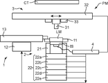
- FIG. 1 is a diagram illustrating a configuration of a camera module manufacturing apparatus according to an embodiment.
- FIG. 1A is a schematic view of a camera module manufacturing apparatus
- FIG. 1B is a functional block diagram of a control calculation unit.
- FIG. 2 is a diagram showing a lens unit used in the camera module manufacturing apparatus shown in FIG.
- FIG. 2A is a schematic cross-sectional view of the lens unit
- FIG. 2A is a plan view of the array lens.
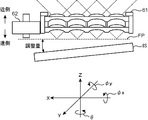
- FIG. 3 is a view for explaining six axes in the camera module manufacturing apparatus shown in FIG.
- the amount of deviation from a predetermined reference posture with respect to the image sensor of the array lens is measured at each of a plurality of positions along the optical axis direction, and an intermediate between the measured amounts of deviation. A value is obtained, and the image sensor is adjusted with respect to the attitude of the array lens at the position where the obtained intermediate value is obtained, whereby a camera module is manufactured.
- the camera module manufactured by this camera module manufacturing method includes a lens module LM including an array lens 61 and an image sensor IS.
- the lens module LM includes an array lens 61, a drive unit 62, and a lens module housing member (not shown) that houses the array lens 61, the drive unit 62, and the like.
- the array lens 61 includes a plurality of imaging optical systems (single eyes) 611 arranged in an array.
- the array lenses 61 are arranged in a two-dimensional array in two linearly independent directions, that is, in the example of FIG. 2, the X direction and the Y direction orthogonal to each other.
- a plurality (16 in 4 rows and 4 columns in FIG. 2) of imaging optical systems 611 is provided.
- Each of the imaging optical systems 611 may be composed of a single lens or a plurality of lenses. In the example shown in FIG. 2, two array lenses are stacked in the optical axis direction while aligning the positions of the corresponding single-lens lenses, and each imaging optical system 611 is composed of two single-lens lenses.
- the array lens 61 is held in a frame body 612 having an inner shape corresponding to the outer shape of the array lens 61, for example, a hollow low-profile prism member 612.
- the array lens 61 includes a light shielding structure 613 that prevents each light received by each imaging optical system 611 from leaking to the adjacent imaging optical system 611.
- a plane including each focal position of each imaging optical system 611 in the array lens 61 is appropriately referred to as a focus plane FP (see FIG. 3).
- the drive unit 62 is a device that moves the array lens 61 along the optical axis direction.
- various actuators such as a voice coil motor and an ultrasonic motor can be used.
- an ultrasonic motor called SIDM (Smooth Impact Drive Mechanism, “SIDM” is a registered trademark) is used.
- SIDM actuator includes an electromechanical transducer such as a piezoelectric element that converts electrical energy into mechanical energy, a drive member that is fixed to one end of the electromechanical transducer and transmits the mechanical energy, and the drive A moving member or the like that is engaged with the member with a predetermined frictional force is provided.
- the SIDM actuator when the electromechanical conversion element (for example, a piezoelectric element) is repeatedly expanded and contracted so that the moving speed of the driving member is asymmetric between the forward path and the backward path, the asymmetric reciprocating motion of the driving member The moving member moves along the longitudinal direction of the driving member, and electric energy is converted into movement of the moving member.
- the SIDM actuator can 61 can be moved in the optical axis direction.
- the array lens 61 shown in FIG. 2 may be the entire imaging optical system that forms an optical image of an object on the imaging surface of the imaging device, or may be a part thereof (the array shown in FIG. 2). There may be a lens in addition to the lens 61).
- the array lens 61 may be a focusing optical system for focusing by moving the array lens 61 along the optical axis direction of the imaging optical system.
- the array lens 61 may be an array.
- the lens 61 may be a zooming optical system for zooming by moving the array lens 61 along the optical axis direction of the imaging optical system.
- the array lens 61 is an optical system for focusing by extending all balls.
- the imaging element IS includes a plurality of photoelectric conversion elements (pixels), and R (red), G according to each light quantity in each optical image of an object (subject) imaged by each imaging optical system 611 of the array lens 61. It is an element that photoelectrically converts the image signals of the respective components (green) and B (blue) and outputs them to an image processing circuit (not shown) that performs predetermined image processing.
- the imaging element IS includes a rectangular package and an imaging surface disposed on the front side of the package.
- the imaging element IS is, for example, a CCD type image sensor, a CMOS type image sensor, or the like.
- the imaging element IS is disposed on the rear surface side (image side) of the array lens 61 of the lens module LM with the imaging surface facing the front side (object side).
- the orientation of the array lens 61 of the lens module LM (the orientation of the focus plane) is adjusted with respect to the imaging device IS, and in this state, the imaging device IS and the array lens 61 of the lens module LM are, for example, an ultraviolet curable adhesive or the like It is fixedly attached by an adhesive such as an energy curable adhesive.
- the imaging element IS is electrically connected to a camera module manufacturing apparatus via a connector or the like during manufacture, and is electrically connected to a camera body or the like via a connector or the like after manufacture.
- the predetermined reference posture is a two-dimensional array in a predetermined row in a plurality of pixels of the image sensor IS arranged in a two-dimensional array with the center position of the array lens 61 coincided with the center position of the image sensor IS.
- the array lens 61 in a plurality of imaging optical systems are aligned with each other, and the orientation of the array lens 61 when the focus plane of the array lens 61 is parallel to the imaging surface of the imaging element IS ( Focus plane attitude).
- Such a camera module is manufactured by a camera module manufacturing apparatus in which the above-described camera module manufacturing method is mounted.
- the camera module manufacturing apparatus PM in this embodiment includes, for example, as shown in FIG. 1, a lens module operation gripping section 1, an image sensor operation gripping section 2, an imaging section 3, and a control calculation section 4.
- an XYZ orthogonal coordinate system is set with the Z axis as the vertical direction (the vertical direction in FIG. 1) with respect to the substantially horizontal installation surface on which the camera module manufacturing apparatus PM is installed. Is done. Therefore, the X axis is set in the direction orthogonal to the Z axis (left and right direction in FIG. 1), and Y in the direction orthogonal to the Z axis and orthogonal to the X axis (front and rear direction (depth direction in FIG. 1)). An axis is set.
- the lens module operation gripper 1 is a device that detachably grips the lens module LM, and the lens module operation gripper 1 is arranged so that the optical axis direction of the array lens 61 in the lens module LM is along the Z-axis direction.
- the lens module LM is detachably held. Therefore, in the array lens 61 and the image sensor IS of the camera module, the above-described XYZ orthogonal coordinate system is set as shown in FIG.
- the camera module manufacturing apparatus PM in the present embodiment mainly adjusts the rotation angle ⁇ around the Z axis, the rotation angle ⁇ x around the X axis, and the rotation angle ⁇ y around the Y axis in such a coordinate system,
- the attitude of the imaging surface of the imaging element IS is adjusted with respect to the array lens 61 of the lens module LM.
- the lens module operation gripping unit 1 that grips the lens module LM so as to be detachable includes a lens module gripping unit 11, a rotation operation unit 12, and a movement operation unit. 13.
- the lens module gripping part 11 detachably grips the lens module LM so as to sandwich the side surface of the housing member (not shown) in the lens module LM.
- the rotation operation unit 12 is for rotating the lens module holding unit 11.
- the lens module gripping unit 11 is rotated by the rotation operation unit 12.
- the movement operation unit 13 operates to move the lens module holding unit 11.
- the movement operation unit 13 moves the lens module gripping unit 11 from the separation position (position shown in FIG. 1A) away from the side of the image sensor gripping unit 21 of the image sensor operation gripping unit 2 described later.
- the moving operation is performed in the horizontal direction up to the position above the grip portion 21 (the position shown in FIG. 9).
- the image sensor operation gripping unit 2 is a device that detachably grips the image sensor IS, and includes an image sensor grip unit 21 that grips the image sensor IS and an image sensor control unit 22 that operates the image sensor grip unit 21. .
- the image sensor gripping part 21 is configured to detachably grip the image sensor IS so as to sandwich the side surface of the package of the image sensor IS.
- the image sensor operation unit 22 is a device that operates the attitude of the image sensor IS with respect to the five axes (X, Y, Z, ⁇ x, ⁇ y) (the attitude of the image pickup surface).
- the Z-axis direction movement operation unit 22a For example, the Z-axis direction movement operation unit 22a; An X-axis direction moving operation unit 22b, a Y-axis direction moving operation unit 22c, and tilting operation units 22d and 22e are provided.
- the Z-axis direction moving operation unit 22a is for moving the image sensor gripping unit 21 in the Z-axis direction.
- the X-axis direction moving operation unit 22b is for moving the image sensor gripping unit 21 in the X-axis direction.
- the Y-axis direction moving operation unit 22c is for moving the image sensor holding unit 21 in the Y-axis direction.
- the tilt operation units 22d and 22e include an X-axis tilt operation unit 22d and a Y-axis tilt operation unit 22e.
- the X-axis tilt operation unit 22d is a plane perpendicular to the Z-axis (an XY plane having the Z-axis as a normal line).
- the Y-axis tilt operation unit 22e tilts the image-capturing element gripping part 21 with respect to the Y-axis direction in the plane perpendicular to the Z-axis. To operate.
- the imaging unit 3 is an apparatus that obtains an image of a subject at a predetermined position.
- the imaging unit 3 includes, for example, a camera 31, a camera movement operation unit 32 that operates to move the camera 31, and an illumination unit 33.
- the camera 31 images a plurality of imaging optical systems 611 in the array lens 61 of the lens module LM held by the lens module holding unit 11 and images the imaging surface of the imaging element IS held by the imaging element holding unit 21.
- the camera movement operation unit 32 moves from the upper position of the lens module holding unit 11 at the separated position shown in FIG. 1A to the upper position of the image pickup device holding unit 21 shown in FIG. 10 is a device for moving and operating the camera 31 to the side position of the image sensor gripping portion 21 shown in FIG.
- the illumination unit 33 illuminates the subject array lens 61 and the image sensor IS when the camera 31 images the array lens 61 and the image sensor IS.
- the control calculation unit 4 controls each part of the camera module manufacturing apparatus PM according to the function of each part in order to manufacture the camera module.
- the control calculation unit 4 is, for example, a CPU (Central Processing Unit), a ROM (Read Only Memory) or an EEPROM (Electrically Erasable Programmable Read Only) that stores various programs executed by the CPU and data necessary for the execution in advance.
- a non-volatile memory element such as Memory
- a volatile memory element such as a RAM (Random Access Memory) serving as a so-called working memory of the CPU
- the control calculation unit 4 may further include a relatively large-capacity storage device such as a hard disk in order to store the image data obtained by the imaging unit 3.
- control calculation unit 4 functionally receives predetermined data such as a control unit 41, a deviation amount calculation unit 42, an intermediate value calculation unit 43, an adjustment unit 44, and image data.
- predetermined data such as a control unit 41, a deviation amount calculation unit 42, an intermediate value calculation unit 43, an adjustment unit 44, and image data.
- a data storage unit 45 to be stored is configured.
- the control unit 41 controls each part of the camera module manufacturing apparatus PM according to the function of each part.
- the displacement amount calculation unit 42 moves the array lens 61 along the optical axis direction (Z-axis direction) by the driving unit 62 of the lens module LM, thereby moving the array lens 61 in the array lens 61 at each of a plurality of positions along the optical axis direction.
- the amount of deviation from a predetermined reference posture is measured.
- the plurality of positions may be three or more, but in the present embodiment, the plurality of positions are moved along the optical axis direction (Z-axis direction) in the array lens 61 in order to shorten the manufacturing time. In the range, the farthest position farthest from the image sensor IS disposed with respect to the array lens 61 and the nearest position closest to the imaging element IS.
- the far side position is a position (near end) that focuses on the closest subject within the focusable distance range of the camera module, and the near side position is focused on a subject that is regarded as infinity. This is the position (end of infinity).
- the deviation amount calculation unit 42 is farthest from the image sensor IS arranged with respect to the array lens 61 in the movement range along the optical axis direction (Z-axis direction) of the array lens 61. The amount of deviation is measured at a far side position, and the amount of deviation is measured at a near side position closest to the imaging element IS arranged with respect to the array lens 61 in the movement range. Then, the deviation amount calculation unit 42 notifies the intermediate value calculation unit 43 of each deviation amount at each of the near side position and the far side position.
- the intermediate value calculation unit 43 obtains intermediate values of a plurality of deviation amounts measured by the deviation amount calculation unit 42.
- the adjustment unit 44 adjusts the posture of the image sensor IS with respect to the posture of the array lens 61 at the position where the intermediate value calculated by the intermediate value calculation unit 43 is obtained, and the lens module operation grip unit 1 and the image sensor operation grip unit
- the array lens 62 is arranged on the image sensor IS by at least one of the two.
- FIG. 4 is a flowchart showing a posture adjustment method in the operation of the camera module manufacturing apparatus shown in FIG.
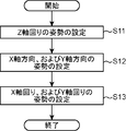
- FIG. 5 is a flowchart showing the adjustment order of each axis in the operation of the camera module manufacturing apparatus shown in FIG.
- FIG. 6 is a diagram for explaining the measurement of the shift amount around the Z axis in the array lens when adjusting around the Z axis.
- FIG. 6A shows the case of the near side position
- FIG. 6B shows the case of the far side position.
- FIG. 7 is a diagram for explaining the measurement of the shift amount around the Z axis in the image sensor when adjusting around the Z axis.
- FIG. 4 is a flowchart showing a posture adjustment method in the operation of the camera module manufacturing apparatus shown in FIG.
- FIG. 5 is a flowchart showing the adjustment order of each axis in the operation of the camera module manufacturing apparatus shown in FIG.
- FIG. 6 is a diagram for explaining the measurement of the shift amount around the Z axis in the array lens
- FIG. 8 is a diagram for explaining adjustment of the shift amount around the Z axis.
- FIG. 9 is a diagram showing a state in which the array lens 61 is arranged on the image sensor IS by adjusting the shift amount around the Z axis.
- FIG. 10 is a diagram illustrating a state of the camera module manufacturing apparatus illustrated in FIG. 1 when the X-axis direction and the Y-axis direction are adjusted, and when the X-axis direction and the Y-axis direction are adjusted.
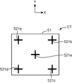
- FIG. 11 is a diagram showing a chart used in the camera module manufacturing apparatus shown in FIG.
- FIG. 12 is a diagram for explaining measurement of each shift amount around the X axis and around the Y axis when adjusting around the X axis and around the Y axis.
- FIG. 13 is a diagram for explaining adjustment of each shift amount around the X axis and around the Y axis.
- FIG. 14 is a diagram for explaining the calculation method of the first aspect for the intermediate value
- the camera module manufacturing apparatus PM When manufacturing the camera module, the camera module manufacturing apparatus PM according to the present embodiment, first, as shown in FIG. 4, first, the amount of deviation from a predetermined reference posture in the array lens 61 is measured at a plurality of positions along the optical axis direction. Each is measured (S1, measurement process), then an intermediate value in a plurality of deviations measured by this process S1 is obtained (S2, intermediate value calculation process), and the intermediate value calculated in process S2 is obtained.
- the attitude of the array lens 61 is adjusted by moving the array lens 61 along the optical axis direction (S3, adjustment step).
- the camera module manufacturing apparatus PM first changes the posture of the array lens 61 around the Z axis by each of the processes S1 to S3 shown in FIG. Then, the attitude of the array lens 61 in the X-axis direction and the Y-axis direction is set (S12, XY-axis) by each of the processes S1 to S3 shown in FIG. The orientation of the array lens 61 around the X axis and the Y axis is set by each of the processing S1 to S3 shown in FIG. 4 (S11, tilt orientation setting step).
- the lens module LM including the array lens 61 is placed on the lens module holding portion 11 at the separated position, and the upper surface of the lens module LM is on the upper side.
- the image sensor IS is gripped by the image sensor grip portion 21 with the imaging surface facing upward.
- the shift amount calculation unit 42 of the control calculation unit 4 performs the array lens 61 of the lens module LM held by the lens module holding unit 11.
- the camera 31 is moved and operated by the camera moving operation unit 32 via the control unit 41.
- the deviation amount calculation unit 42 and the adjustment unit 44 operate each unit via the control unit 41, but hereinafter, “via the control unit 41” is appropriately omitted.
- the shift amount calculation unit 42 moves the array lens 61 to the near position along the optical axis direction (Z-axis direction) by the driving unit 62 of the lens module LM, and in this state, moves the array lens 61 upward by the camera 31.
- the deviation amount calculation unit 42 acquires, from the camera 31, a captured image of the array lens 61 (a captured image on the near side position around the Z axis) at the near position captured by the camera 31.
- the deviation amount calculation unit 42 moves the array lens 61 to the far side position along the optical axis direction (Z-axis direction) by the driving unit 62 of the lens module LM, and in this state, the camera 31 performs the array lens 61. Is imaged from above.
- the deviation amount calculation unit 42 acquires, from the camera 31, a captured image of the array lens 61 (far-side position captured image about the Z axis) captured at the far side position captured by the camera 31.
- the captured image is acquired by moving the array lens 61 to the near side position, and the captured image is acquired by moving the array lens 61 to the far side position.
- the captured image may be acquired by moving to the position and acquiring the captured image and moving the array lens 61 to the near position. The same applies to the following.
- the shift amount calculation unit 42 that has acquired the Z-axis near-side position captured image and the Z-axis far-side position captured image based on the Z-axis near-side position captured image and the Z-axis far-side position captured image, respectively.
- the deviation amounts ⁇ 1 and ⁇ 2 at the rotation angle ⁇ around the Z axis of the array lens 61 with respect to a preset reference line RL (shown in FIG. 6, one of the reference postures) are detected. More specifically, for example, in the present embodiment, the deviation amount calculation unit 42 is configured to center the imaging optical systems 611 arranged in a line as illustrated in FIG.
- the array line AL1 is generated by detecting and sequentially connecting the detected centers.
- the deviation amount calculation unit 42 detects an angle ⁇ 1 formed by the array line AL1 and the reference line RL as a deviation amount ⁇ 1.
- the deviation amount calculation unit 42 detects the centers of the imaging optical systems 611 arranged in a line with respect to the Z-axis far side position captured image, and sequentially detects the detected centers.
- An array line AL2 is generated by connecting the lines.
- the deviation amount calculation unit 42 detects an angle ⁇ 2 formed by the array line AL2 and the reference line RL as a deviation amount ⁇ 2. Then, the deviation amount calculation unit 42 notifies the intermediate value calculation unit 43 of these detected deviation amounts ⁇ 1 and ⁇ 2.
- the intermediate value calculation unit 43 that has received the notifications of the respective shift amounts ⁇ 1 and ⁇ 2 detected by the shift amount calculation unit 42 is an intermediate value in the shift amount ⁇ 1 at the near side position and the shift amount ⁇ 2 at the far side position. ⁇ m is obtained.
- the displacement amount calculation unit 42 then moves the camera 31 by the camera movement operation unit 32 to a position above the image pickup surface of the image pickup element IS held by the image pickup element holding unit 21.
- the deviation amount calculation unit 42 images the imaging surface of the imaging element IS from above with the camera 31.
- the deviation amount calculation unit 42 acquires a captured image (imaging element captured image) of the imaging surface of the imaging element IS captured by the camera 31 from the camera 31.
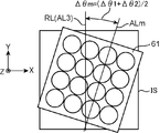
- the deviation amount calculation unit 42 that has acquired the image pickup element picked-up image detects the amount of deviation ⁇ 3 at the rotation angle ⁇ around the Z axis of the image pickup element IS with respect to the reference line RL based on the image pickup element picked-up image. More specifically, for example, in the present embodiment, the deviation amount calculation unit 42 detects the edge of each pixel (photoelectric conversion element) PX aligned in a row as illustrated in FIG. The array line AL3 is generated by detecting and sequentially connecting the detected edges. Then, the deviation amount calculation unit 42 detects an angle ⁇ 3 formed by the array line AL3 and the reference line RL as a deviation amount ⁇ 3 of the imaging element IS. The detection of the deviation amount ⁇ 3 is not limited to this form.
- the detection on the photoelectric conversion elements arranged in a line is performed.
- the array line AL3 may be generated by detecting the center of each microlens and connecting the detected centers in order, and the shift amount ⁇ 3 may be detected. Then, the deviation amount calculation unit 42 notifies the adjustment unit 44 of the detected deviation amount ⁇ 3 at the rotation angle ⁇ around the Z axis of the imaging element IS.
- the adjustment unit 44 receives the notification of the intermediate value ⁇ m and the shift amount ⁇ 3 of the image sensor IS, the adjustment unit 44 first sets the reference line RL to the array line AL3 (around the Z axis of the image sensor IS as shown in FIG. 8).
- the lens module gripping unit 11 is rotated by the rotation operation unit 12 so as to match the posture.
- the adjustment unit 44 moves the array lens 61 along the optical axis direction by the drive unit 62 so as to obtain an intermediate value ⁇ m in order to adjust the posture around the Z axis. More specifically, the adjustment unit 44 images the array lens 61 with the camera 31 and detects the rotation angle ⁇ around the Z axis of the array lens 61, while the drive unit 62 moves the array lens 61 along the optical axis direction.
- the array lens 61 is stopped at a position where the rotation angle around the Z axis becomes an intermediate value ⁇ m, moving from one end (for example, the near side position) to the other end (for example, the far side position). Then, as shown in FIG. 9, the adjustment unit 44 moves the lens module gripping unit 11 to a position above the image sensor gripping unit 21 of the image sensor operation gripping unit 2 by the movement operation unit 13. As a result, the posture around the Z axis between the focus plane FP of the array lens 61 of the lens module LM and the imaging surface of the imaging element IS is adjusted and arranged in that state.
- the shift amount calculation unit 42 of the control calculation unit 4 includes a camera as shown in FIG.
- the camera 31 is moved to the side position of the image sensor gripping portion 21 shown in FIG.
- the chart CT disposed above the image sensor operation gripping portion 2 faces the image sensor IS, and the image sensor IS can image the chart CT as a subject.
- the chart CT is formed in a rectangular shape and includes a test pattern image 521 drawn on one main surface of the chart plate 51.
- the test pattern image 521 of the present embodiment has a cross-shaped (X-shaped) first test pattern image 521a arranged at a substantially central position, and the same pattern arranged at the four corners of the rectangle.
- the displacement amount calculation unit 42 moves the array lens 61 to the near side position along the optical axis direction (Z-axis direction) by the driving unit 62 of the lens module LM, and in this state, the image pickup element IS performs each imaging optical operation.
- Each captured image (each chart near side position captured image) of the chart CT by the system (each individual eye) is acquired.
- the shift amount calculation unit 42 moves the array lens 61 to the far side position along the optical axis direction (Z-axis direction) by the driving unit 62 of the lens module LM, and in this state, each image pickup from the image sensor IS.
- Each captured image (each chart far-side position captured image) of the chart CT by the optical system (each individual eye) is acquired.
- the shift amount calculation unit 42 that has acquired the respective chart near-side position captured images and the respective chart far-side position captured images acquires the array lens 61 based on the respective chart near-side position captured images and the respective chart far-side position captured images.
- the respective displacement amounts ⁇ x1, ⁇ x2, ⁇ y1, and ⁇ y2 of the position X in the X-axis direction and the position Y in the Y-axis direction of the array lens 61 with respect to the center position are detected. More specifically, for example, in the present embodiment, the shift amount calculation unit 42 sets the cross intersection of the center first test pattern image 521a with respect to the focused image in each chart near-side position captured image.
- the deviation amount calculation unit 42 detects the cross intersection of the center first test pattern image 521a for the focused image in each chart far side position captured image, and the detected intersection and the chart far distance are detected.
- Differences in the X-axis direction and the Y-axis direction from the center of the side-position captured image are detected as deviation amounts ⁇ x2 and ⁇ y2 at the position X in the X-axis direction and the position Y in the Y-axis direction.
- the deviation amount calculation unit 42 notifies the intermediate value calculation unit 43 of the detected deviation amounts ⁇ x1, ⁇ x2, ⁇ y1, and ⁇ y2.
- the intermediate value calculation unit 43 that has received the notification of the respective shift amounts ⁇ x1, ⁇ x2, ⁇ y1, and ⁇ y2 detected by the shift amount calculation unit 42 is in the near-side position with respect to the X-axis direction and the Y-axis direction, respectively.
- the intermediate values ⁇ xm and ⁇ ym of the shift amounts ⁇ x1 and ⁇ y1 and the far-side shift amounts ⁇ x2 and ⁇ y2 are obtained.
- the intermediate values ⁇ xm and ⁇ ym are average values of the shift amounts ⁇ x1 and ⁇ y1 at the near side position and the shift amounts ⁇ x2 and ⁇ y2 at the far side position.
- the intermediate value calculation unit 43 notifies the adjustment unit 44 of the obtained intermediate values ⁇ xm and ⁇ ym.
- the adjustment unit 44 adjusts the intermediate values ⁇ xm and ⁇ ym in order to adjust the posture in the X-axis direction and the Y-axis direction.
- the drive unit 62 moves the array lens 61 along the optical axis direction. More specifically, the adjustment unit 44 images the chart CT with the imaging element IS and detects the position X in the X-axis direction and the position Y in the Y-axis direction of the array lens 61, while the array lens 61 is driven by the drive unit 62.
- the array lens 61 is stopped at a position where the intermediate value ⁇ xm and the intermediate value ⁇ ym in the Y-axis direction are reached. Thereby, the postures in the X-axis direction and the Y-axis direction between the focus plane FP of the array lens 61 of the lens module LM and the imaging surface of the imaging element IS are adjusted.
- the intermediate values ⁇ xm and ⁇ ym are obtained to adjust the array lens 61 of the lens module LM and the image pickup surface and posture of the image pickup element IS.
- the posture is adjusted in the following simple manner. Also good. That is, the adjustment unit 44 first moves the array lens 61 by the drive unit 62 to a central position in a range along the optical axis direction (Z-axis direction) from the near side position to the far side position. .
- the adjusting unit 44 based on the test pattern images 521a to 521e in the captured image of the chart CT acquired from the image sensor IS, the X-axis direction and the Y-axis direction of the imaging surface of the image sensor IS gripped by the image sensor gripper 21 Adjust the axial position. More specifically, the adjustment unit 44 uses the X-axis direction movement operation unit 21b and the Y-axis direction movement operation unit 21c so that the first test pattern image 521a is positioned at the center of the captured image of the chart CT. The gripper 21 is moved and operated in the X-axis direction and the Y-axis direction. Thereby, the postures in the X-axis direction and the Y-axis direction between the array lens 61 of the lens module LM and the imaging surface of the imaging element IS are adjusted.
- the deviation amount calculation unit of the control calculation unit 4 12A the array lens 61 is moved to the near side position along the optical axis direction (Z-axis direction) by the drive unit 62 of the lens module LM, and the image sensor IS is moved by the image sensor operation unit 22, as shown in FIG. 12A. While moving in the Z-axis direction, an image of the chart CT is acquired by the imaging element IS.
- the deviation amount calculation unit 42 scans the image sensor IS along the Z-axis direction by the image sensor operation unit 22 via the control unit 41, and the second to fifth test pattern images 521b at the four corners in the chart CT.
- the in-focus positions (positions in focus) of each of ⁇ 521e are detected.
- the shift amount calculation unit 42 uses the shift amount of the rotation angle around the X axis as the inclination information about the X axis (the XY plane with the Z axis as the normal line (1 of the reference posture).
- the tilt amount about the X-axis from ⁇ ) and ⁇ Yx1 and the amount of deviation about the Y-axis (the tilt about the Y-axis from the XY plane) ⁇ y1 are obtained as the Y-axis tilt information.
- deviation amounts ⁇ x1 and ⁇ y1 from a predetermined reference posture at the near side position in the array lens 61 are obtained.
- the deviation amount calculation unit 42 moves the array lens 61 to the far side position along the optical axis direction (Z-axis direction) by the driving unit 62 of the lens module LM.
- Deviation amounts ⁇ x2 and ⁇ y2 from a predetermined reference posture at the far side position in the lens 61 are obtained.
- the deviation amount calculation unit 42 notifies the intermediate value calculation unit 43 of the deviation amounts ⁇ x1, ⁇ x2, ⁇ y1, and ⁇ y2 at the near side position and the far side position, respectively.
- the intermediate value calculation unit 43 that has received the notification of each of the shift amounts ⁇ x1, ⁇ x2, ⁇ y1, and ⁇ y2 detected by the shift amount calculation unit 42 is located in the near side position with respect to the X-axis direction and the Y-axis direction, respectively.
- the intermediate values ⁇ xm and ⁇ ym of the shift amounts ⁇ x1 and ⁇ y1 and the shift amounts ⁇ x2 and ⁇ y2 at the far side are obtained.
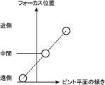
- the intermediate values ⁇ xm and ⁇ ym have the deviation amounts ⁇ x1 and ⁇ y1 at the near side position and the deviation amounts ⁇ x2 and ⁇ at the far side position as shown in FIG.
- the intermediate value calculation unit 43 notifies the adjustment unit 44 of the obtained intermediate values ⁇ xm and ⁇ ym.
- the adjustment unit 44 that has received the notification of the intermediate values ⁇ xm and ⁇ ym in the X-axis direction and the Y-axis direction performs an intermediate operation to adjust the posture around the X-axis and the Y-axis (inclination of the focus plane FP).
- the drive unit 62 moves the array lens 61 along the optical axis direction so that the values ⁇ xm and ⁇ ym are obtained. More specifically, the adjustment unit 44 images the chart CT with the imaging element IS and detects the rotation angle ⁇ x around the X axis and the rotation angle ⁇ y around the Y axis of the array lens 61, while the array is performed by the drive unit 62.
- the lens 61 is moved from one end (for example, near position) to the other end (for example, far position) of the moving range along the optical axis direction, and the rotation angle ⁇ x around the X axis and the rotation angle ⁇ y around the Y axis Stops the array lens 61 at a position where the intermediate value ⁇ xm around the X axis and the intermediate value ⁇ ym around the Y axis are reached.
- the adjustment unit 44 has a rotation angle ⁇ x around the X axis and a rotation angle ⁇ y around the Y axis within a predetermined range (within an allowable range around the X axis) centered on an intermediate value ⁇ xm around the X axis.
- the array lens 61 may be stopped at a position within a predetermined range centered on the intermediate value ⁇ ym around the Y axis (within the allowable range around the Y axis). That is, the adjusting unit 44 may stop the array lens 61 at a position in the vicinity of the intermediate value ⁇ xm around the X axis and the intermediate value ⁇ ym around the Y axis.
- the allowable range around the X axis and the allowable range around the Y axis are appropriately set in advance according to, for example, manufacturing tolerances. As a result, the postures around the X axis and the Y axis (inclination of the focus plane FP) between the focus plane FP of the array lens 61 and the imaging surface of the imaging element IS in the lens module LM are adjusted.
- the array lens 61 and the imaging element IS in the lens module LM are fixedly attached with an adhesive such as an energy curable adhesive such as an ultraviolet curable adhesive.
- the camera module manufacturing apparatus PM and the manufacturing method mounted thereon when the camera module is manufactured, the orientation of the array lens 61 is adjusted by an intermediate value of a plurality of deviation amounts. The For this reason, compared with the case where the attitude of the array lens 61 is not adjusted by the intermediate value, the maximum value of the shift amount is reduced. Therefore, the camera module manufacturing apparatus PM and the manufacturing method mounted thereon in this embodiment are Even if a dynamic tilt occurs, it is possible to manufacture a camera module in which each shift at each position along the optical axis direction is suppressed.
- the position of the array lens 61 around the Z axis is adjusted so as to be the intermediate value ⁇ m of the deviation amount around the Z axis, and the intermediate value ⁇ xm of the deviation amount around the X axis and the Y axis are adjusted.
- the position around the X axis and the position around the Y axis in the array lens 61 are adjusted so that the intermediate value ⁇ ym of the amount of misalignment is obtained.
- the camera module manufacturing apparatus PM and the manufacturing method mounted thereon in the present embodiment can reduce the repetition of adjustment by adjusting the position around the Z axis with relatively low adjustment sensitivity first, Manufacturing time can be shortened.
- the deviation amount calculation unit 42 moves the array lens 61 to the near side position and the far side position, respectively, and obtains a captured image of the chart CT.
- the respective deviation amounts ⁇ x, ⁇ y of the respective positions in the X-axis direction and the Y-axis direction, and the respective deviation amounts ⁇ x, ⁇ y of the respective rotation angles around the X-axis and the Y-axis (inclination of the focus plane FP) Is calculated, but from the captured image of the chart CT acquired when obtaining the shift amounts ⁇ x, ⁇ y (inclination of the focus plane FP) of the respective rotation angles around the X axis and the Y axis, the X axis direction and the Y You can calculate the amount of deviation ⁇ x, ⁇ y at each position in the axial direction. .
- the deviation amount calculation unit 42 moves the camera 31 as described above, moves the array lens 61 to the near side position, and the image sensor operation unit 22
- the imaging element IS is scanned along the Z-axis direction, and the focus positions of the second to fifth test pattern images 521b to 521e of the chart CT are detected.
- the deviation amount calculation unit 42 uses each of the focused second to fifth test pattern images 521b to 521e, and similarly to the above, each deviation amount of each position in the X-axis direction and the Y-axis direction.
- ⁇ x1 and ⁇ y1 are detected, and in the same manner as described above, the shift amounts ⁇ x1 and ⁇ y1 of the rotation angles around the X axis and the Y axis are obtained based on the detected in-focus positions.
- the shift amount calculation unit 42 moves the array lens 61 to the far side position, scans the image sensor IS along the Z-axis direction by the image sensor operation unit 22, and the second to fifth test pattern images of the chart CT.
- the in-focus positions of 521b to 521e are detected.
- the deviation amount calculation unit 42 uses each of the focused second to fifth test pattern images 521b to 521e, and similarly to the above, each deviation amount of each position in the X-axis direction and the Y-axis direction.
- ⁇ x2 and ⁇ y2 are detected, and in the same manner as described above, the shift amounts ⁇ x2 and ⁇ y2 of the rotation angles around the X axis and the Y axis are obtained based on the detected focus positions.
- the shift amounts ⁇ x and ⁇ y at the respective positions in the X-axis direction and the Y-axis direction are adjusted, but this may be omitted.
- the posture of the array lens 61 is represented by a rotation angle ⁇ around the Z axis, a rotation angle ⁇ x around the X axis, and a rotation angle ⁇ y around the Y axis.
- the camera module manufacturing apparatus PM and In the mounted manufacturing method the attitude of the array lens 61 is adjusted by the amount of deviation ⁇ of the rotation angle about the Z axis, the amount of deviation ⁇ x of the rotation angle about the X axis, and the amount of deviation ⁇ y of the rotation angle about the Y axis.
- An image picked up by a camera module that uses the array lens 61 and moves the array lens 61 along the optical axis direction includes a rotation angle ⁇ around the Z axis, a rotation angle ⁇ x around the X axis, and a rotation angle ⁇ y around the Y axis. Is relatively affected by the posture represented by.
- such a camera module manufacturing apparatus PM and a manufacturing method mounted thereon adjust the posture of the array lens 61 by adjusting the rotation angle ⁇ about the Z axis, the rotation angle ⁇ x about the X axis, and the Y axis.
- the rotation angle ⁇ y By limiting to the adjustment of the posture represented by the rotation angle ⁇ y, it is possible to effectively adjust while reducing the number of adjustments. Therefore, such a camera module manufacturing apparatus PM and a manufacturing method mounted thereon can shorten the manufacturing time and effectively suppress each displacement at each position along the optical axis direction even if a dynamic tilt occurs.
- the camera module can be manufactured.
- the intermediate values ⁇ m, ⁇ xm, ⁇ ym, ⁇ xm, and ⁇ ym are obtained as the first mode from the shift amount of the near side position and the shift amount of the far side position.
- the intermediate values ⁇ m, ⁇ xm, ⁇ ym, ⁇ xm, and ⁇ ym may be obtained by the calculation method of the following second mode or third mode.
- FIG. 15 is a diagram for explaining a calculation method according to the second mode for intermediate values.
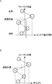
- 15A shows the distribution of the deviation amount ⁇ x around the X axis and the deviation amount ⁇ y around the Y axis (inclination of the focus plane FP), and
- FIG. 15B shows the deviation amount ⁇ x (or the center point deviation of the array lens 61).
- the distribution of ⁇ y) is shown.
- FIG. 16 is a diagram for explaining the calculation method of the third aspect for the intermediate value.
- the deviation amount calculation unit 42 moves the array lens 61 along the optical axis direction (Z-axis direction) by the driving unit 62 of the lens module LM, thereby moving the array lens 61 along the optical axis direction (a plurality of positions ( The amount of deviation of the array lens 61 from a predetermined reference posture is measured at each of the three or more positions), and the intermediate value calculation unit 43 determines the maximum value and the minimum value of the plurality of deviation amounts measured by the deviation amount calculation unit 42. Find the intermediate value for.
- the shift amount calculation unit 42 moves the camera 31 to the side position of the image sensor holding unit 21 shown in FIG. 10 by the camera moving operation unit 32 via the control unit 41 so that the chart CT faces the image sensor IS.
- the deviation amount calculation unit 42 moves the array lens 61 to any one of the plurality of positions along the optical axis direction (Z-axis direction) by the driving unit 62 of the lens module LM, and the image sensor operation unit.
- the image of the chart CT is acquired by the image sensor IS while moving the image sensor IS in the Z-axis direction by 22.
- the deviation amount calculation unit 42 scans the image sensor IS along the Z-axis direction by the image sensor operation unit 22, and focuses each of the second to fifth test pattern images 521b to 521e at the four corners in the chart CT. Detect position. Then, based on the detected in-focus positions, the deviation amount calculation unit 42 obtains the inclination ⁇ x1 about the X axis and the inclination ⁇ y1 about the Y axis as the Y axis inclination information. As a result, deviation amounts ⁇ x1 and ⁇ y1 from the predetermined reference posture in the array lens 61 are obtained.
- the shift amount calculation unit 42 moves the array lens 61 to any other position of the plurality of positions along the optical axis direction (Z-axis direction) by the driving unit 62 of the lens module LM.
- Deviation amounts ⁇ x2 and ⁇ y2 from the predetermined reference posture in the array lens 61 are obtained.
- the deviation amount calculation unit 42 obtains a deviation amount from a predetermined reference posture in the array lens 61 at each of the plurality of positions, and each of the obtained deviation amounts.
- To the intermediate value calculation unit 43 An example of each shift amount at each position along the optical axis direction measured in this way is shown in FIG. 15A.
- the intermediate value calculation unit 43 has a maximum value (maximum shift amount in the positive direction with the reference posture as the origin 0) and a minimum value (reference posture as the origin 0) in each of the plurality of shift amounts measured by the shift amount calculation unit 42. Find the intermediate value for the maximum amount of deviation in the negative direction.
- the amount of deviation is measured at each of five different first to fifth positions from the near side position to the far side position, and the amount of deviation is the maximum value at the second position.
- the deviation amount is the minimum value at three positions. Therefore, in the example illustrated in FIG. 15A, the intermediate value calculation unit 43 includes the maximum value of the shift amount at the second position measured by the shift amount calculation unit 42 and the third position measured by the shift amount calculation unit 42. These intermediate values are obtained from the minimum value of the deviation amount at.
- FIG. 15B shows an example of each deviation amount at each position along the optical axis direction when adjusting each deviation amount ⁇ x, ⁇ y at each position in the X-axis direction and Y-axis direction.
- the amount of deviation is measured at each of five different first to fifth positions from the near side position to the far side position, the deviation amount is the maximum value at the second position, and at the third position.
- the amount of deviation is the minimum value. Therefore, in the example illustrated in FIG. 15B, the intermediate value calculation unit 43 includes the maximum value of the shift amount at the second position measured by the shift amount calculation unit 42 and the third position measured by the shift amount calculation unit 42. These intermediate values are obtained from the minimum value of the deviation amount at.
- each displacement amount at each position along the optical axis direction is shown in FIG. As such, it occurs with random (random) values.
- the camera module manufacturing apparatus PM using the calculation method of the second aspect and the manufacturing method mounted thereon have an intermediate value from the maximum value and the minimum value of the deviation amount most deviated from the reference posture. Therefore, the posture can be adjusted effectively. Therefore, the camera module manufacturing apparatus PM and the manufacturing method mounted on the camera module manufacturing apparatus PM using the calculation method of the second aspect as described above are effective for each shift at each position along the optical axis direction even if a dynamic tilt occurs. It is possible to manufacture a camera module that is suppressed.
- the deviation amount calculation unit 42 moves the array lens 61 from one of the moving ranges along the optical axis direction (Z-axis direction) to the other, thereby obtaining an XY plane at the center point of the array lens 61.
- XY movement range is measured, and the shift amounts ⁇ xa and ⁇ ya around the X axis and Y axis are measured at a position along the optical axis direction giving one end of the measured XY movement range.
- the deviation amounts ⁇ xb and ⁇ yb around the X axis and the Y axis are measured at a position along the optical axis direction that gives the other end of the measured XY movement range.
- the plurality of positions are the XY movement ranges in the XY plane at the center point of the array lens 61 obtained by moving the array lens 61 from one of the movement ranges along the optical axis direction (Z-axis direction) to the other. These are both positions along the optical axis direction that give both ends.
- the intermediate value calculator 43 determines the intermediate values ⁇ xm, ⁇ at each shift amount at both positions of the array lens 61 along the optical axis direction that gives both ends of the XY movement range measured by the shift amount calculator 42. Find ⁇ ym.
- the shift amount calculation unit 42 causes the camera 31 to move the camera 31 by the camera movement operation unit 32 via the control unit 41 so that the chart CT faces the image sensor IS. Move to the side position 21.
- the shift amount calculation unit 42 moves the array lens 61 along the optical axis direction (Z-axis direction) from the near side position to the far side position by the driving unit 62 of the lens module LM, while the chart CT uses the imaging element IS. Sampling and obtaining images.
- the deviation amount calculation unit 42 determines the deviation of the center point of the array lens 61 from the center point of the entire image and the cross point of the first test pattern image 521a from each sampled chart CT image. The amounts ⁇ x and ⁇ y are obtained.
- the shift amount calculation unit 42 is a drive unit of the lens module LM at a position along the optical axis direction that gives one end P1 of the XY movement range.
- the array lens 61 is moved by 62, and the image of the chart CT is acquired by the image sensor IS while moving the image sensor IS in the Z-axis direction by the image sensor operation unit 22.
- the deviation amount calculation unit 42 scans the image sensor IS along the Z-axis direction by the image sensor operation unit 22 via the control unit 41, and the second to fifth test pattern images 521b at the four corners in the chart CT. The in-focus positions of ⁇ 521e are detected. Then, the deviation amount calculation unit 42 obtains a deviation amount ⁇ xa around the X axis and a deviation amount ⁇ ya around the Y axis based on the detected in-focus positions. Thus, the shift amounts ⁇ xa and ⁇ ya at the position along the optical axis direction that gives the one end P1 of the XY movement range are obtained.
- the shift amount calculation unit 42 is at a position along the optical axis direction that gives the other end P2 of the XY movement range, and the drive unit 62 of the lens module LM.
- the array lens 61 is moved, and similarly, the shift amounts ⁇ xb and ⁇ yb at the position along the optical axis direction giving the one end P2 of the XY movement range are obtained.
- the deviation amount calculation unit 42 notifies the intermediate value calculation unit 43 of each deviation amount at both positions of the array lens 61 along the optical axis direction that gives both ends of the XY movement range.
- the intermediate value calculator 43 determines the intermediate values ⁇ xm, ⁇ at each shift amount at both positions of the array lens 61 along the optical axis direction that gives both ends of the XY movement range measured by the shift amount calculator 42. Find ⁇ ym.
- the shift amount in the XY plane at the center point of the array lens 61 is the shift amount ⁇ x of the rotation angle around the X axis and the rotation angle around the Y axis when the optical axis direction is the Z axis direction.
- the camera module manufacturing apparatus PM using the calculation method of the second aspect and the manufacturing method mounted on the camera module need only have a minimum number of measurements at both ends of the XY movement range as the plurality of positions.
- the posture can be adjusted effectively from the proportional relationship. Therefore, such a camera module manufacturing apparatus PM and a manufacturing method mounted thereon can shorten the manufacturing time and effectively suppress each displacement at each position along the optical axis direction even if a dynamic tilt occurs.
- the camera module can be manufactured.
- a method of manufacturing a camera module wherein an amount of deviation from a predetermined reference posture with respect to an imaging element of an array lens including a plurality of imaging optical systems arranged in an array is respectively determined at a plurality of positions along the optical axis direction.
- a measuring step for measuring, an intermediate value calculating step for obtaining an intermediate value in a plurality of deviation amounts measured by the measuring step, and an attitude of the array lens at a position where the intermediate value is calculated in the intermediate value calculating step And an adjustment step of adjusting the posture of the image sensor.
- the measurement step may be performed on an image sensor disposed with respect to the array lens in a movement range along the optical axis direction of the array lens.
- a far side position measuring step for measuring the amount of deviation at the farthest far side position; and the amount of deviation at the closest side position with respect to the imaging device arranged with respect to the array lens in the movement range.
- the amount of deviation is measured at the far side position, the amount of deviation is measured at the near side position, and the intermediate amount is based on the amount of deviation at each of these positions.
- a value is determined. For example, when the array lens is moved along the optical axis direction by an actuator such as a voice coil motor, there is a characteristic that the absolute value of the deviation amount is maximized at both end positions of the far side position and the near side position. is there. For this reason, when the camera module has the above characteristics, such a manufacturing method of the camera module suffices to measure the minimum number of the both end positions as the plurality of positions. Can be adjusted. Therefore, such a manufacturing method of the camera module can reduce the manufacturing time, and can manufacture a camera module that effectively suppresses each shift at each position along the optical axis direction even when a dynamic tilt occurs.
- the array lens is aligned along the optical axis direction.
- An XY movement range measurement step of measuring an XY movement range in the XY plane at the center point of the array lens by moving from one to the other of the movement ranges, and the XY movement measured by the XY movement range measurement step One end position measuring step of measuring the deviation amount at a position along the optical axis direction giving one end of the range, and the optical axis giving the other end of the XY moving range measured by the XY moving range measuring step
- the plurality of positions are preferably moved along the optical axis direction when an XYZ orthogonal coordinate system with the optical axis as the Z axis is set. Both positions along the optical axis direction provide both ends of the XY movement range in the XY plane at the center point of the array lens obtained by moving from one side of the range to the other.
- the amounts of deviation are measured at both ends of the XY movement range in the XY plane at the center point of the array lens, and based on the amounts of deviation at these positions.
- the intermediate value is determined.
- the amount of deviation in the XY plane at the center point of the array lens is respectively the amount of deviation of rotation about the X axis and the amount of deviation of rotation about the Y axis when the optical axis direction is the Z axis direction. Proportional. For this reason, such a manufacturing method of the camera module requires only a minimum number of measurements at both ends of the XY movement range as the plurality of positions, and can effectively adjust the posture from the proportional relationship. Therefore, the manufacturing method of such a camera module can shorten the manufacturing time, and can manufacture a camera module that effectively suppresses each shift at each position along the optical axis direction even when a dynamic tilt occurs.
- the intermediate value calculation step obtains intermediate values for the maximum value and the minimum value in a plurality of deviation amounts measured by the measurement step.
- each shift amount at each position along the optical axis direction is a random (random) value. It occurs in.
- the manufacturing method of such a camera module is such that the maximum deviation amount (the maximum deviation amount in the positive direction with the reference orientation as the origin 0) and the minimum value (the reference orientation as the origin 0 and minus) with the most deviation from the reference orientation. Since the intermediate value is obtained from the maximum deviation amount in the direction), the posture can be adjusted effectively. Therefore, such a method for manufacturing a camera module can manufacture a camera module that effectively suppresses each shift at each position along the optical axis direction even when a dynamic tilt occurs.
- the orientation of the array lens is determined by setting a rotation angle ⁇ around the Z axis when an XYZ orthogonal coordinate system having the optical axis as the Z axis is set. , The rotation angle ⁇ x around the X axis and the rotation angle ⁇ y around the Y axis.
- the posture of the array lens is represented by a rotation angle ⁇ around the Z axis, a rotation angle ⁇ x around the X axis, and a rotation angle ⁇ y around the Y axis.
- the posture of the array lens is adjusted by the rotation angle ⁇ around the Z axis, the rotation angle ⁇ x around the X axis, and the rotation angle ⁇ y around the Y axis.
- a camera module that uses an array lens to move the array lens along the optical axis in the X-axis, Y-axis, Z-axis, Z-axis rotation, X-axis rotation, and Y-axis rotation.
- the posture that greatly affects the image picked up by is the posture represented by the rotation angle ⁇ around the Z axis, the rotation angle ⁇ x around the X axis, and the rotation angle ⁇ y around the Y axis.
- the manufacturing method of such a camera module is limited by adjusting the posture of the array lens to the posture adjustment by rotation around the Z axis, rotation around the X axis, and rotation around the Y axis. It is possible to adjust effectively while reducing the number of times. Therefore, such a manufacturing method of the camera module can reduce the manufacturing time, and can manufacture a camera module that effectively suppresses each shift at each position along the optical axis direction even when a dynamic tilt occurs.
- the adjustment step adjusts a position around the Z axis in the array lens so that the intermediate value around the Z axis is adjusted.
- the position around the X axis and the position around the Y axis in the array lens are adjusted so that the intermediate value around the X axis and the intermediate value around the Y axis are obtained.
- an XY axis adjustment step is performed.
- Such a camera module manufacturing method can reduce the repetition of the adjustment and shorten the manufacturing time by adjusting the position around the Z-axis with relatively low adjustment sensitivity first.
- An apparatus for manufacturing a camera module includes an array lens including a plurality of imaging optical systems arranged in an array, and a drive unit that moves the array lens along the optical axis direction.
- a lens module operation gripping unit that detachably grips the lens module
- an image sensor operation gripping unit that detachably grips the image sensor
- the drive unit that moves the array lens along the optical axis direction.
- a measuring unit for measuring a deviation amount from a predetermined reference posture in the array lens at each of a plurality of positions along the optical axis direction, and an intermediate for obtaining an intermediate value in the plurality of deviation amounts measured by the measuring unit A posture of the image sensor with respect to a posture of the array lens at a position that is an intermediate value calculated by a value calculator and the intermediate value calculator Adjusted, and an adjustment unit for placing the array lens on the imaging element by at least one of said lens module operating grip portion and the image pickup device operation grip part.
- such a camera module manufacturing apparatus when the camera module is manufactured, the orientation of the array lens is adjusted by an intermediate value of a plurality of shift amounts. For this reason, since the maximum value of the absolute value of the deviation amount is reduced as compared with the case where the posture is not adjusted by the intermediate value, such a camera module manufacturing apparatus is capable of operating in the optical axis direction even if a dynamic tilt occurs. It is possible to manufacture a camera module in which each shift at each position along the line is suppressed.
- a camera module manufacturing method and manufacturing apparatus can be provided.
Landscapes
- Engineering & Computer Science (AREA)
- Multimedia (AREA)
- Signal Processing (AREA)
- Studio Devices (AREA)
- Lens Barrels (AREA)
Abstract
本発明にかかるカメラモジュールの製造方法および製造装置では、アレイレンズにおける所定の基準姿勢からのズレ量が光軸方向に沿った複数の位置でそれぞれ測定され、その中間値となるように、前記アレイレンズを前記光軸方向に沿って移動することで前記アレイレンズの姿勢が調整される。
Description
本発明は、カメラモジュールを製造するカメラモジュールの製造方法および製造装置に関する。
カメラモジュールは、物体(被写体)の光学像を結像面(撮像面)に結像し、この撮像面に結像された被写体の光学像を撮像する装置である。このカメラモジュールは、通常、被写体の光学像を結像面に結像する撮像光学系と、前記結像面に撮像面を配置し、この撮像面に結像された被写体の光学像を撮像する撮像素子と、これら撮像光学系および撮像素子を保持する筐体その他の部材とを備える。また、カメラモジュールは、自動焦点機能(オートフォーカス機能)や変倍機能(ズーム機能)を持つ場合には、前記撮像光学系に含まれる1または複数のレンズを光軸方向に沿って移動する駆動部をさらに備える。このようなカメラモジュールは、撮像光学系に多軸調整を行って撮像素子を取り付けることによって製造され、その製造方法は、例えば、特許文献1に開示されている。
この特許文献1に開示されたカメラモジュール製造方法は、測定チャートに直交するZ軸上に撮影レンズと前記撮影レンズによって結像されるチャート像を撮像する撮像素子とをセットし、前記Z軸上に予め離散的に設定された複数の測定位置に前記撮影レンズまたは撮像素子のいずれかを順次に移動して撮像を行い、前記撮像素子の撮像面上に設定された少なくとも5つの撮像位置から得られる撮像信号に基づいて各々の撮像位置での合焦度合を表す個別の合焦評価値を前記複数の測定位置ごとに算出し、前記撮像位置の各々について所定の合焦評価値が得られたときにそれぞれのZ軸上の位置を合焦座標値とする合焦座標値取得工程と、前記撮像面をZ軸に直交するXY座標平面に対応させたときの各撮像位置のXY座標値と、それぞれの撮像位置ごとに得られたZ軸上の合焦座標値との組み合わせで表される少なくとも5つの評価点を前記XY座標平面とZ軸とを組み合わせた三次元座標系に展開したときに、これらの評価点の相対位置に基づいて前記三次元座標系で一平面として表される近似結像面を算出する結像面算出工程と、前記Z軸と前記近似結像面との交点である結像面座標値と、前記XY座標平面に対する前記近似結像面のX軸及びY軸回りの回転角度とを算出する調整値算出工程と、前記結像面座標値及び回転角度に基づいて、前記撮像素子のZ軸上での位置とX軸及びY軸回りの傾きとを調整し、前記撮像面を前記近似結像面に一致させる調整工程と、を含む。そして、前記近似結像面の算出には、最小自乗法が用いられる。
一方、近年、カメラモジュールの薄型化(低背化)のために、撮像光学系には、複数の撮像光学系(個眼)をアレイ状に配列したアレイレンズが用いられる。このアレイレンズを用いたカメラモジュールでは、個々の個眼によって形成された被写体の光学像を1個の撮像素子における各領域でそれぞれ撮像することによって複数の画像(個眼画像)が得られ、これら複数の個眼画像をいわゆる超解像処理することによって1つの画像が形成される。これによってアレイレンズを用いたカメラモジュールは、薄型化を達成しつつ、1個の撮像光学系で前記1個の撮像素子全体に被写体の光学像を形成した場合と略同等の解像度の画像を生成できる。
ところで、オートフォーカスまたは変倍では、オートフォーカスまたは変倍を行うために、そのための1または複数のレンズが光軸方向に沿って移動される。この移動を行うと、光軸に対する直進性の誤差によって、撮像光学系に撮像素子を調整して組み付けた際における前記1または複数のレンズの姿勢(調整姿勢)から、前記移動に伴って前記1または複数のレンズの姿勢がずれてしまう動チルトが生じる場合がある。アレイレンズを用いたカメラモジュールの製造に、特許文献1に開示されたカメラモジュール製造方法を用いた場合、この動チルトが生じると、アレイレンズ全体が撮像素子に対して傾くことから、アレイレンズの中心から外れた個眼の姿勢だけでなく、アレイレンズの中心付近の個眼の姿勢も調整姿勢からずれてしまい、個々の個眼で撮像素子に結像する像位置がずれてしまう。
本発明は、上述の事情に鑑みて為された発明であり、その目的は、動チルトが生じても光軸方向に沿った個々の位置における各ずれを抑制することができる、アレイレンズを用いたカメラモジュールを製造できるカメラモジュールの製造方法および製造装置を提供することである。
本発明にかかるカメラモジュールの製造方法および製造装置では、アレイレンズにおける所定の基準姿勢からのズレ量が光軸方向に沿った複数の位置でそれぞれ測定され、その中間値となるように、前記アレイレンズを前記光軸方向に沿って移動することで前記アレイレンズの姿勢が調整される。このため、本発明にかかるカメラモジュールの製造方法および製造装置は、動チルトが生じても光軸方向に沿った個々の位置における各ずれを抑制した、アレイレンズを用いたカメラモジュールを製造できる。
上記並びにその他の本発明の目的、特徴及び利点は、以下の詳細な記載と添付図面から明らかになるであろう。
以下、本発明にかかる実施の一形態を図面に基づいて説明する。なお、各図において同一の符号を付した構成は、同一の構成であることを示し、適宜、その説明を省略する。また、本明細書において、総称する場合には添え字を省略した参照符号で示し、個別の構成を指す場合には添え字を付した参照符号で示す。
図1は、実施形態におけるカメラモジュールの製造装置の構成を示す図である。図1Aは、カメラモジュールの製造装置の概略図であり、図1Bは、制御演算部の機能ブロック図である。図2は、図1に示すカメラモジュールの製造装置で用いられるレンズユニットを示す図である。図2Aは、レンズユニットの概略断面図であり、図2Aは、アレイレンズの平面図である。図3は、図1に示すカメラモジュールの製造装置における6軸を説明するための図である。
本実施形態におけるカメラモジュールの製造方法は、アレイレンズの撮像素子に対する所定の基準姿勢からのズレ量を光軸方向に沿った複数の位置でそれぞれ測定し、これら測定された複数のズレ量における中間値を求め、この求めた中間値となる位置でのアレイレンズの姿勢に対して撮像素子を調整し、これによって、カメラモジュールを製造する。
このカメラモジュールの製造方法によって製造されるカメラモジュールは、アレイレンズ61を含むレンズモジュールLMと、撮像素子ISとを備える。
レンズモジュールLMは、例えば、図2に示すように、アレイレンズ61と、駆動部62と、これらアレイレンズ61および駆動部62等を収容する図略のレンズモジュール収容部材とを備える。
アレイレンズ61は、アレイ状に配列された複数の撮像光学系(個眼)611を備える。本実施形態では、図2Aに示すように、アレイレンズ61は、線形独立な2方向、この図2の例では、互いに直交するX方向およびY方向の2方向に2次元アレイ状に配列された複数(図2では4行4列の16個)の撮像光学系611を備えている。各撮像光学系611それぞれは、1枚のレンズで構成されてもよく、また複数枚のレンズで構成されてもよい。図2に示す例では、2枚のアレイレンズが、互いに対応する個眼のレンズにおける位置を合わせつつ光軸方向に積層されており、各撮像光学系611は、2枚の個眼のレンズで構成されている。そして、アレイレンズ61は、アレイレンズ61の外形状に応じた内形状を持つ枠体612内、例えば、中空低背の角柱部材612内に保持される。また、アレイレンズ61は、各撮像光学系611それぞれで受光した各光が隣接する撮像光学系611に漏れ出すことを防ぐ遮光構造613を備えている。なお、アレイレンズ61における各撮像光学系611の各焦点位置を含む平面が、ピント平面FP(図3参照)と適宜に呼称される。
駆動部62は、アレイレンズ61を光軸方向に沿って移動させる装置である。駆動部62は、例えば、ボイスコイルモータや超音波モータ等の種々のアクチュエータを用いることができる。本実施形態では、占有体積に比し比較的大きなトルクが得られることから、例えば、SIDM(Smooth Impact Drive Mechanism、「SIDM」は登録商標)と呼ばれる超音波モータが用いられる。このSIDMのアクチュエータは、電気エネルギーを機械エネルギーに変換する例えば圧電素子等の電気機械変換素子、前記電気機械変換素子の一方端部に固定され前記機械エネルギーが伝達される駆動部材、および、前記駆動部材に所定の摩擦力で係合される移動部材等を備えている。このSIDMのアクチュエータでは、前記駆動部材を往路と復路とでその移動速度が非対称となるように前記電気機械変換素子(例えば圧電素子)を繰り返し伸縮させると、この駆動部材の非対称な往復運動により、前記移動部材が前記駆動部材の長手方向に沿って移動し、電気エネルギーが移動部材の運動に変換される。このようなSIDMのアクチュエータにおける前記移動部材にアレイレンズ61の枠体612を固定することによって、あるいは、アレイレンズ61の枠体612を前記移動部材と兼用することによって、SIDMのアクチュエータは、アレイレンズ61を光軸方向に移動できる。
そして、図2に示すアレイレンズ61は、物体の光学像を撮像素子の撮像面上に結像する撮像光学系の全部であってよく、またはその一部であってよい(図2に示すアレイレンズ61の他にレンズがあってよい)。また、アレイレンズ61は、該アレイレンズ61を前記撮像光学系の光軸方向に沿って移動することによって合焦するための合焦用(フォーカス用)の光学系であってよく、あるいは、アレイレンズ61は、該アレイレンズ61を前記撮像光学系の光軸方向に沿って移動することによって変倍するための変倍用(ズーム用)の光学系であってよい。図2に示す例では、アレイレンズ61は、全玉繰り出しによるフォーカス用の光学系である。
撮像素子ISは、複数の光電変換素子(画素)を備え、アレイレンズ61の各撮像光学系611によって結像された物体(被写体)の各光学像における各光量に応じてR(赤)、G(緑)、B(青)の各成分の画像信号にそれぞれ光電変換して、所定の画像処理を行う画像処理回路(不図示)へ出力する素子である。撮像素子ISは、矩形状のパッケージと、前記パッケージの前面側に配設された撮像面とを備える。撮像素子ISは、例えば、CCD型のイメージセンサや、CMOS型のイメージセンサ等である。
そして、本実施形態では、撮像素子ISは、撮像面を前方側(対物側)に向けてレンズモジュールLMのアレイレンズ61の後面側(像側)に配設され、上述のカメラモジュールの製造方法によって、撮像素子ISに対しレンズモジュールLMのアレイレンズ61の姿勢(ピント平面の姿勢)が調整され、その状態で、撮像素子ISとレンズモジュールLMのアレイレンズ61とが例えば紫外線硬化性接着剤等のエネルギー硬化型接着剤等の接着剤によって固定的に取り付けられる。なお、この撮像素子ISは、製造中ではコネクター等を介してカメラモジュールの製造装置に電気的に接続され、製造後ではコネクター等を介してカメラ本体等に電気的に接続される。
ここで、前記所定の基準姿勢は、撮像素子ISの中心位置にアレイレンズ61の中心位置を一致させ、2次元アレイ状に配列された撮像素子ISの複数の画素における所定の一列に2次元アレイ状に配列されたアレイレンズ61の複数の撮像光学系における所定の一列を一致させ、そして、撮像素子ISの撮像面にアレイレンズ61のピント平面を平行にさせた場合におけるアレイレンズ61の姿勢(ピント平面の姿勢)である。
このようなカメラモジュールは、上述のカメラモジュールの製造方法を実装したカメラモジュールの製造装置によって製造される。この実施形態におけるカメラモジュールの製造装置PMは、例えば、図1に示すように、レンズモジュール操作把持部1と、撮像素子操作把持部2と、撮像部3と、制御演算部4とを備える。
まず、カメラモジュールの製造装置PMおよびカメラモジュールの座標系について説明する。本実施形態では、図1Aに示すように、カメラモジュールの製造装置PMが設置される略水平な設置面に対し垂直方向(図1で紙面上下方向)をZ軸としたXYZ直交座標系が設定される。したがって、Z軸に直交する方向(図1で紙面左右方向)にX軸が設定され、これらZ軸に直交するとともにX軸に直交する方向(図1で紙面前後方向(奥行き方向))にY軸が設定される。そして、レンズモジュール操作把持部1は、レンズモジュールLMを脱着自在に把持する装置であり、レンズモジュール操作把持部1は、レンズモジュールLMにおけるアレイレンズ61の光軸方向がZ軸方向に沿うように、レンズモジュールLMを脱着自在に把持する。したがって、カメラモジュールのアレイレンズ61および撮像素子ISにおいて、上述のXYZ直交座標系は、図3に示すように、設定されることになる。本実施形態におけるカメラモジュールの製造装置PMは、主に、このような座標系におけるZ軸回りの回転角度θ、X軸回りの回転角度φxおよびY軸回りの回転角度φyを調整することで、レンズモジュールLMのアレイレンズ61に対し、撮像素子ISの撮像面の姿勢を調整する。
図1に戻って、このようなレンズモジュールLMを脱着自在に把持するレンズモジュール操作把持部1は、例えば、本実施形態では、レンズモジュール把持部11と、回動操作部12と、移動操作部13とを備えている。
レンズモジュール把持部11は、レンズモジュールLMにおける図略の前記収容部材の側面を挟持するようにしてレンズモジュールLMを着脱自在に把持するものである。回動操作部12は、レンズモジュール把持部11を回動操作するものである。この回動操作部12によってレンズモジュール把持部11が回動操作される。これによってレンズモジュール把持部11に把持されたレンズモジュールLMのアレイレンズ61が、光軸と平行なZ軸回りに回動される。移動操作部13は、レンズモジュール把持部11を移動操作する。この実施形態では、移動操作部13は、レンズモジュール把持部11を、後述の撮像素子操作把持部2の撮像素子把持部21の側方に離れた離間位置(図1Aに示す位置)から撮像素子把持部21の上方位置(図9に示す位置)まで、水平方向に移動操作する。
撮像素子操作把持部2は、撮像素子ISを脱着自在に把持する装置であり、撮像素子ISを把持する撮像素子把持部21と、撮像素子把持部21を操作する撮像素子操作部22とを備える。
撮像素子把持部21は、撮像素子ISの前記パッケージの側面を挟持するようにして撮像素子ISを着脱自在に把持するものである。撮像素子操作部22は、5軸(X、Y、Z、φx、φy)に対する撮像素子ISの姿勢(撮像面の姿勢)を操作する装置であり、例えば、Z軸方向移動操作部22aと、X軸方向移動操作部22bと、Y軸方向移動操作部22cと、傾動操作部22d、22eとを備えている。Z軸方向移動操作部22aは、Z軸方向に撮像素子把持部21を移動操作するものである。X軸方向移動操作部22bは、X軸方向に撮像素子把持部21を移動操作するものである。Y軸方向移動操作部22cは、Y軸方向に撮像素子把持部21を移動操作するものである。傾動操作部22d、22eは、X軸傾動操作部22dと、Y軸傾動操作部22eとを備え、X軸傾動操作部22dは、Z軸に垂直な平面(Z軸を法線とするXY平面)におけるX軸方向に対して撮像素子把持部21を傾動操作するものであり、Y軸傾動操作部22eは、Z軸に垂直な前記平面におけるY軸方向に対して撮像素子把持部21を傾動操作するものである。
撮像部3は、所定位置における被写体の画像を得る装置であり、本実施形態では、例えば、カメラ31と、カメラ31を移動操作するカメラ移動操作部32と、照明部33とを備える。
カメラ31は、レンズモジュール把持部11に把持されたレンズモジュールLMのアレイレンズ61における複数の撮像光学系611を撮像するとともに、撮像素子把持部21に把持された撮像素子ISの撮像面を撮像する装置である。カメラ移動操作部32は、図1Aに示す離間位置のレンズモジュール把持部11の上方位置から、図7に示す撮像素子把持部21の上方位置、さらに、撮像素子把持部21を挟んで上記離間位置と反対側の図10に示す撮像素子把持部21の側方位置まで、カメラ31を移動操作する装置である。照明部33は、カメラ31でアレイレンズ61や撮像素子ISを撮像する際に、被写体のアレイレンズ61や撮像素子ISを照明する。
制御演算部4は、カメラモジュールを製造するべく、カメラモジュールの製造装置PMの各部を当該各部の機能に応じてそれぞれ制御するものである。制御演算部4は、例えば、CPU(Central Processing Unit)、このCPUによって実行される種々のプログラムやその実行に必要なデータ等を予め記憶するROM(Read Only Memory)やEEPROM(Electrically Erasable Programmable Read Only Memory)等の不揮発性記憶素子、このCPUのいわゆるワーキングメモリとなるRAM(Random Access Memory)等の揮発性記憶素子およびその周辺回路等を備えたマイクロコンピュータによって構成される。なお、制御演算部4は、撮像部3によって得られた画像データ等を記憶するために、例えばハードディスク等の比較的大容量の記憶装置をさらに備えてもよい。そして、制御演算部4には、プログラムを実行することによって、機能的に、制御部41、ズレ量演算部42、中間値演算部43、調整部44、および、画像データ等の所定のデータを記憶するデータ記憶部45が構成される。
制御部41は、カメラモジュールの製造装置PMの各部を当該各部の機能に応じてそれぞれ制御するものである。
ズレ量演算部42は、レンズモジュールLMの駆動部62によってアレイレンズ61を光軸方向(Z軸方向)に沿って移動することによって前記光軸方向に沿った複数の位置それぞれでアレイレンズ61における所定の基準姿勢からのズレ量を測定する。前記複数の位置は、3箇所以上であってよいが、本実施形態では、製造時間を短縮するために、前記複数の位置は、アレイレンズ61における光軸方向(Z軸方向)に沿った移動範囲において、アレイレンズ61に対して配置される撮像素子ISに対し、最も離れる遠側位置および最も近接する近側位置である。前記遠側位置は、カメラモジュールの合焦可能な距離範囲において、最も近接する被写体に対し合焦する位置(近接端)であり、前記近側位置は、無限遠と見なされる被写体に対し合焦する位置(無限遠端)である。すなわち、本実施形態では、ズレ量演算部42は、アレイレンズ61における光軸方向(Z軸方向)に沿った移動範囲において、アレイレンズ61に対して配置される撮像素子ISに対し、最も離れる遠側位置で前記ズレ量を測定し、前記移動範囲において、アレイレンズ61に対して配置される撮像素子ISに対し、最も近接する近側位置で前記ズレ量を測定するものである。そして、ズレ量演算部42は、これら近側位置および遠側位置それぞれにおける各ズレ量を中間値演算部43へ通知する。
中間値演算部43は、ズレ量演算部42によって測定された複数のズレ量における中間値を求めるものである。
調整部44は、中間値演算部43で演算された中間値となる位置でのアレイレンズ61の姿勢に対して撮像素子ISの姿勢を調整し、レンズモジュール操作把持部1および撮像素子操作把持部2のうちの少なくとも一方によって撮像素子ISにアレイレンズ62を配置するものである。
次に、本実施形態におけるカメラモジュールの製造装置PMの動作について説明する。図4は、図1に示すカメラモジュールの製造装置の動作における姿勢調整方法を示すフローチャートである。図5は、図1に示すカメラモジュールの製造装置の動作における各軸の調整順を示すフローチャートである。図6は、Z軸回りを調整する場合において、アレイレンズにおけるZ軸回りのズレ量の測定を説明するための図である。図6Aは、近側位置の場合を示し、図6Bは、遠側位置の場合を示す。図7は、Z軸回りを調整する場合において、撮像素子におけるZ軸回りのズレ量の測定を説明するための図である。図8は、Z軸回りのズレ量の調整を説明するための図である。図9は、Z軸回りのズレ量を調整してアレイレンズ61を撮像素子ISに配設した状態を示す図である。図10は、X軸方向およびY軸方向を調整する場合、ならびに、X軸回りおよびY軸回りを調整する場合における、図1に示すカメラモジュールの製造装置の状態を示す図である。図11は、図1に示すカメラモジュールの製造装置で用いられるチャートを示す図である。図12は、X軸回りおよびY軸回りを調整する場合におけるX軸回りおよびY軸回りの各ズレ量の測定を説明するための図である。図13は、X軸回りおよびY軸回りの各ズレ量の調整を説明するための図である。図14は、中間値における第1態様の演算方法を説明するための図である。
本実施形態におけるカメラモジュールの製造装置PMは、カメラモジュールの製造に際し、図4に示すように、まず、アレイレンズ61における所定の基準姿勢からのズレ量を光軸方向に沿った複数の位置でそれぞれ測定し(S1、測定工程)、次に、この処理S1によって測定された複数のズレ量における中間値を求め(S2、中間値演算工程)、そして、処理S2で演算された中間値となるようにアレイレンズ61を光軸方向に沿って移動することでアレイレンズ61の姿勢を調整する(S3、調整工程)。
より具体的には、本実施形態におけるカメラモジュールの製造装置PMは、図5に示すように、まず、図4に示す処理S1ないし処理S3の各処理によってZ軸回りのアレイレンズ61の姿勢を設定し(S11、Z軸回り姿勢設定工程)、次に、図4に示す処理S1ないし処理S3の各処理によってX軸方向およびY軸方向のアレイレンズ61の姿勢を設定し(S12、XY軸方向姿勢設定工程)、そして、図4に示す処理S1ないし処理S3の各処理によってX軸回りおよびY軸回りのアレイレンズ61の姿勢を設定する(S11、傾き姿勢設定工程)。
すなわち、本実施形態におけるカメラモジュールの製造装置PMでは、まず、図1Aに示すように、アレイレンズ61を含むレンズモジュールLMが離間位置のレンズモジュール把持部11に、レンズモジュールLMの上面を上側にして把持され、撮像素子ISが撮像素子把持部21に、撮像面を上側にして把持される。
この状態から、Z軸回りの回転角度θのズレ量△θを調整するために、制御演算部4のズレ量演算部42は、レンズモジュール把持部11に把持されたレンズモジュールLMのアレイレンズ61の上方位置に、制御部41を介してカメラ移動操作部32によってカメラ31を移動操作する。なお、ズレ量演算部42および調整部44は、制御部41を介して各部を操作するが、以下、「制御部41を介して」を適宜省略する。ズレ量演算部42は、レンズモジュールLMの駆動部62によってアレイレンズ61を光軸方向(Z軸方向)に沿って近側位置に移動し、その状態で、カメラ31によってアレイレンズ61を上方側から撮像する。そして、ズレ量演算部42は、カメラ31によって撮像された近側位置におけるアレイレンズ61の撮像画像(Z軸回り近側位置撮像画像)を、カメラ31から取得する。次に、ズレ量演算部42は、レンズモジュールLMの駆動部62によってアレイレンズ61を光軸方向(Z軸方向)に沿って遠側位置に移動し、その状態で、カメラ31によってアレイレンズ61を上方側から撮像する。そして、ズレ量演算部42は、カメラ31によって撮像された遠側位置におけるアレイレンズ61の撮像画像(Z軸回り遠側位置撮像画像)を、カメラ31から取得する。なお、上述では、アレイレンズ61を近側位置に移動して撮像画像が取得されてアレイレンズ61を遠側位置に移動して撮像画像が取得されたが、逆に、アレイレンズ61を遠側位置に移動して撮像画像が取得されてアレイレンズ61を近側位置に移動して撮像画像が取得されてもよい。以下も同様である。
これらZ軸回り近側位置撮像画像およびZ軸回り遠側位置撮像画像を取得したズレ量演算部42は、これらZ軸回り近側位置撮像画像およびZ軸回り遠側位置撮像画像それぞれに基づいて、予め設定した基準線RL(図6に図示、基準姿勢の1つ)に対するアレイレンズ61のZ軸回りの回転角度θにおける各ズレ量△θ1、△θ2をそれぞれ検出する。より具体的には、例えば、本実施形態では、ズレ量演算部42は、Z軸回り近側位置撮像画像に対し、図6Aに示すように、一列に並んだ各撮像光学系611の中心を検出し、その検出した中心を順次に結ぶことによって配列線AL1を生成する。そして、ズレ量演算部42は、その配列線AL1と基準線RLとのなす角度△θ1をズレ量△θ1として検出する。同様に、ズレ量演算部42は、Z軸回り遠側位置撮像画像に対し、図6Bに示すように、一列に並んだ各撮像光学系611の中心を検出し、その検出した中心を順次に結ぶことによって配列線AL2を生成する。そして、ズレ量演算部42は、その配列線AL2と基準線RLとのなす角度△θ2をズレ量△θ2として検出する。そして、ズレ量演算部42は、これら検出した各ズレ量△θ1、△θ2を中間値演算部43に通知する。
これらズレ量演算部42によって検出された各ズレ量△θ1、△θ2の通知を受けた中間値演算部43は、近側位置のズレ量△θ1および遠側位置のズレ量△θ2における中間値△θmを求める。本実施形態では、近側位置および遠側位置の2箇所であるので、中間値△θmは、近側位置のズレ量△θ1と遠側位置のズレ量△θ2との平均値となる(△θm=(△θ1+△θ2)/2)。そして、中間値演算部43は、この求めた中間値△θmを調整部44に通知する。
一方、ズレ量演算部42は、その後、撮像素子把持部21に把持された撮像素子ISの撮像面の上方位置に、カメラ移動操作部32によってカメラ31を移動操作する。ズレ量演算部42は、その状態で、カメラ31によって撮像素子ISの撮像面を上方側から撮像する。そして、ズレ量演算部42は、カメラ31によって撮像された撮像素子ISの撮像面の撮像画像(撮像素子撮像画像)を、カメラ31から取得する。
この撮像素子撮像画像を取得したズレ量演算部42は、撮像素子撮像画像に基づいて、前記基準線RLに対する撮像素子ISのZ軸回りの回転角度θにおけるズレ量△θ3を検出する。より具体的には、例えば、本実施形態では、ズレ量演算部42は、撮像素子撮像画像に対し、図7に示すように、一列に並んだ各画素(光電変換素子)PXの端縁を検出し、その検出した端縁を順次に結ぶことによって配列線AL3を生成する。そして、ズレ量演算部42は、その配列線AL3と基準線RLとのなす角度△θ3を撮像素子ISのズレ量△θ3として検出する。なお、このズレ量△θ3の検出は、この形態に限らず、例えば、撮像素子ISにおける各光電変換素子の撮像面上にマイクロレンズを備える場合には、一列に並んだ各光電変換素子上の各マイクロレンズの中心を検出し、その検出した中心を順次に結ぶことによって配列線AL3が生成され、ズレ量△θ3が検出されてもよい。そして、ズレ量演算部42は、この検出した撮像素子ISのZ軸回りの回転角度θにおけるズレ量△θ3を調整部44に通知する。
上述の中間値△θmおよび撮像素子ISのズレ量△θ3の通知を受けた調整部44は、まず、図8に示すように、基準線RLを配列線AL3(撮像素子ISのZ軸回りの姿勢)に合わせるように、回動操作部12によってレンズモジュール把持部11を回動操作する。そして、調整部44は、Z軸回りの姿勢を調整するために、中間値△θmとなるように駆動部62によってアレイレンズ61を光軸方向に沿って移動する。より具体的には、調整部44は、カメラ31でアレイレンズ61を撮像してアレイレンズ61のZ軸回りの回転角度θを検出しつつ、駆動部62によってアレイレンズ61を光軸方向に沿った移動範囲の一方端(例えば近側位置)から他方端(例えば遠側位置)へ向けて移動し、Z軸回りの回転角度が中間値△θmとなった位置でアレイレンズ61を停止する。そして、調整部44は、図9に示すように、移動操作部13によってレンズモジュール把持部11を撮像素子操作把持部2の撮像素子把持部21の上方位置まで移動操作する。これによってレンズモジュールLMのアレイレンズ61のピント平面FPと撮像素子ISの撮像面とのZ軸回りの姿勢が調整され、その状態で配設される。
次に、X軸方向の位置のズレ量△xおよびY軸方向の位置のズレ量△yを調整するために、制御演算部4のズレ量演算部42は、図10に示すように、カメラ移動操作部32によってカメラ31を図10に示す撮像素子把持部21の側方位置まで移動する。これによって、撮像素子操作把持部2の上方位置に配設されているチャートCTが撮像素子ISに臨み、撮像素子ISがチャートCTを被写体として撮像できるようになる。
チャートCTは、矩形状に形成されており、チャート板51の一主面上に描画されたテストパターン像521を備える。本実施形態のテストパターン像521は、図11に示すように略中央位置に配設された十字状(X字状)の第1テストパターン像521aと、矩形の四隅にそれぞれ配設された同様の十字状(X字状)の第2ないし第5テストパターン像521b~521eとを備える。
そして、ズレ量演算部42は、レンズモジュールLMの駆動部62によってアレイレンズ61を光軸方向(Z軸方向)に沿って近側位置に移動し、その状態で、撮像素子ISから各撮像光学系(各個眼)によるチャートCTの各撮像画像(各チャート近側位置撮像画像)を取得する。次に、ズレ量演算部42は、レンズモジュールLMの駆動部62によってアレイレンズ61を光軸方向(Z軸方向)に沿って遠側位置に移動し、その状態で、撮像素子ISから各撮像光学系(各個眼)によるチャートCTの各撮像画像(各チャート遠側位置撮像画像)を取得する。
これら各チャート近側位置撮像画像および各チャート遠側位置撮像画像を取得したズレ量演算部42は、これら各チャート近側位置撮像画像および各チャート遠側位置撮像画像それぞれに基づいて、アレイレンズ61の中央位置に対するアレイレンズ61のX軸方向の位置XおよびY軸方向の位置Yにおける各ズレ量△x1、△x2、△y1、△y2をそれぞれ検出する。より具体的には、例えば、本実施形態では、ズレ量演算部42は、各チャート近側位置撮像画像における合焦している画像に対し、中央の第1テストパターン像521aの十字の交差点を検出し、その検出した交差点とこのチャート近側位置撮像画像の中心(基準姿勢の1つ)とのX軸方向およびY軸方向の各差を、X軸方向の位置XおよびY軸方向の位置Yにおける各ズレ量△x1、△y1として検出する。同様に、ズレ量演算部42は、各チャート遠側位置撮像画像における合焦している画像に対し、中央の第1テストパターン像521aの十字の交差点を検出し、その検出した交差点とチャート遠側位置撮像画像の中心とのX軸方向およびY軸方向の各差を、X軸方向の位置XおよびY軸方向の位置Yにおける各ズレ量△x2、△y2として検出する。そして、ズレ量演算部42は、これら検出した各ズレ量△x1、△x2、△y1、△y2を中間値演算部43に通知する。
これらズレ量演算部42によって検出された各ズレ量△x1、△x2、△y1、△y2の通知を受けた中間値演算部43は、X軸方向およびY軸方向それぞれに対し、近側位置のズレ量△x1、△y1および遠側位置のズレ量△x2、△y2における各中間値△xm、△ymを求める。本実施形態では、上述と同様に理由により、中間値△xm、△ymは、近側位置のズレ量△x1、△y1と遠側位置のズレ量△x2、△y2との平均値となる(△xm=(△x1+△x2)/2、△ym=(△y1+△y2)/2)。そして、中間値演算部43は、これら求めた各中間値△xm、△ymを調整部44に通知する。
これらX軸方向およびY軸方向における各中間値△xm、△ymの通知を受けた調整部44は、X軸方向およびY軸方向の姿勢を調整するために、中間値△xm、△ymとなるように駆動部62によってアレイレンズ61を光軸方向に沿って移動する。より具体的には、調整部44は、撮像素子ISでチャートCTを撮像してアレイレンズ61のX軸方向の位置XおよびY軸方向の位置Yを検出しつつ、駆動部62によってアレイレンズ61を光軸方向に沿った移動範囲の一方端(例えば近側位置)から他方端(例えば遠側位置)へ向けて移動し、X軸方向の位置XおよびY軸方向の位置YがX軸方向の中間値△xmおよびY軸方向の中間値△ymとなった位置でアレイレンズ61を停止する。これによってレンズモジュールLMのアレイレンズ61のピント平面FPと撮像素子ISの撮像面とのX軸方向およびY軸方向の姿勢が調整される。
なお、上述では、中間値△xm、△ymを求めてレンズモジュールLMのアレイレンズ61と撮像素子ISの撮像面と姿勢が調整されたが、次のように簡略されて前記姿勢が調整されてもよい。すなわち、調整部44は、まず、近側位置から遠側位置までの光軸方向(Z軸方向)に沿った範囲における中央位置に、調整部44は、駆動部62によってアレイレンズ61を移動する。そして、調整部44は、撮像素子ISから取得したチャートCTの撮像画像におけるテストパターン像521a~521eに基づいて、撮像素子把持部21に把持された撮像素子ISの撮像面のX軸方向及びY軸方向の位置を調整する。より具体的には、調整部44は、第1テストパターン像521aがチャートCTの撮像画像の中央に位置するように、X軸方向移動操作部21bおよびY軸方向移動操作部21cによって、撮像素子把持部21をX軸方向およびY軸方向に移動操作する。これによってレンズモジュールLMのアレイレンズ61と撮像素子ISの撮像面とのX軸方向およびY軸方向の姿勢が調整される。
次に、X軸回りの回転角度φxのズレ量△φxおよびY軸回りの回転角度φyのズレ量△φy(ピント平面FPの傾き)を調整するために、制御演算部4のズレ量演算部42は、図12Aに示すように、レンズモジュールLMの駆動部62によってアレイレンズ61を光軸方向(Z軸方向)に沿って近側位置に移動し、撮像素子操作部22によって撮像素子ISをZ軸方向に移動しながら撮像素子ISによってチャートCTの画像を取得する。この際に、ズレ量演算部42は、制御部41を介して撮像素子操作部22によって撮像素子ISをZ軸方向に沿って走査し、チャートCTにおける四隅の第2ないし第5テストパターン像521b~521eそれぞれの合焦位置(ピントが合う位置)を検出する。そして、ズレ量演算部42は、これら検出した各合焦位置に基づいて、X軸回り傾斜情報としてX軸回りの回転角度のズレ量(Z軸を法線とするXY平面(基準姿勢の1つ)からのX軸回りの傾き)△φx1およびY軸回り傾斜情報としてY軸回りのズレ量(XY平面からのY軸回りの傾き)△φy1を求める。これによってアレイレンズ61における近側位置での所定の基準姿勢からのズレ量△φx1、△φy1が求められる。そして、ズレ量演算部42は、図12Bに示すように、レンズモジュールLMの駆動部62によってアレイレンズ61を光軸方向(Z軸方向)に沿って遠側位置に移動し、同様に、アレイレンズ61における遠側位置での所定の基準姿勢からのズレ量△φx2、△φy2を求める。そして、ズレ量演算部42は、これら近側位置および遠側位置それぞれにおける各ズレ量△φx1、△φx2、△φy1、△φy2を中間値演算部43へ通知する。
これらズレ量演算部42によって検出された各ズレ量△φx1、△φx2、△φy1、△φy2の通知を受けた中間値演算部43は、X軸方向およびY軸方向それぞれに対し、近側位置のズレ量△φx1、△φy1および遠側位置のズレ量△φx2、△φy2における各中間値△φxm、△φymを求める。本実施形態では、上述と同様に理由により、中間値△φxm、△φymは、図14に示すように、近側位置のズレ量△φx1、△φy1と遠側位置のズレ量△φx2、△φy2との平均値となる(△φxm=(△φx1+△φx2)/2、△φym=(△φy1+△φy2)/2)。そして、中間値演算部43は、これら求めた各中間値△φxm、△φymを調整部44に通知する。
これらX軸方向およびY軸方向における各中間値△φxm、△φymの通知を受けた調整部44は、X軸回りおよびY軸回りの姿勢(ピント平面FPの傾き)を調整するために、中間値△φxm、△φymとなるように駆動部62によってアレイレンズ61を光軸方向に沿って移動する。より具体的には、調整部44は、撮像素子ISでチャートCTを撮像してアレイレンズ61のX軸回りの回転角度φxおよびY軸回りの回転角度φyを検出しつつ、駆動部62によってアレイレンズ61を光軸方向に沿った移動範囲の一方端(例えば近側位置)から他方端(例えば遠側位置)へ向けて移動し、X軸回りの回転角度φxおよびY軸回りの回転角度φyがX軸回りの中間値△φxmおよびY軸回りの中間値△φymとなった位置でアレイレンズ61を停止する。なお、調整部44は、X軸回りの回転角度φxおよびY軸回りの回転角度φyが、X軸回りの中間値△φxmを中心とする所定の範囲内(X軸回り許容範囲内)であってY軸回りの中間値△φymを中心とする所定の範囲内(Y軸回り許容範囲内)である場合に、その位置でアレイレンズ61を停止してもよい。すなわち、調整部44は、X軸回りの中間値△φxmおよびY軸回りの中間値△φymの近傍の位置でアレイレンズ61を停止してもよい。X軸回り許容範囲およびY軸回り許容範囲は、例えば、製造公差等に応じて適宜に予め設定される。これによってレンズモジュールLMにおけるアレイレンズ61のピント平面FPと撮像素子ISの撮像面とのX軸回りおよびY軸回りの姿勢(ピント平面FPの傾き)が調整される。
そして、上述したように、その状態で、例えば紫外線硬化性接着剤等のエネルギー硬化型接着剤等の接着剤によって、レンズモジュールLMにおけるアレイレンズ61と撮像素子ISとが固定的に取り付けられる。
以上説明したように、本実施形態におけるカメラモジュールの製造装置PMおよびこれに実装された製造方法は、カメラモジュールを製造する際に、アレイレンズ61の姿勢が複数のズレ量の中間値で調整される。このため、アレイレンズ61の姿勢を前記中間値で調整しない場合に較べて、ズレ量の最大値が低減されるから、本実施形態におけるカメラモジュールの製造装置PMおよびこれに実装された製造方法は、動チルトが生じても光軸方向に沿った個々の位置における各ずれを抑制した、カメラモジュールを製造できる。
また、上述の実施形態では、Z軸回りのズレ量の中間値△θmとなるようにアレイレンズ61におけるZ軸回りの位置が調整され、X軸回りのズレ量の中間値△φxmおよびY軸回りのズレ量の中間値△φymとなるようにアレイレンズ61におけるX軸回りの位置およびY軸回りの位置が調整される。このように本実施形態におけるカメラモジュールの製造装置PMおよびこれに実装された製造方法は、相対的に調整感度の低いZ軸回りの位置を先に調整することで、調整の繰り返しを低減でき、製造時間を短縮できる。
なお、上述の実施形態では、X軸方向およびY軸方向の各位置の各ズレ量△x、△yを調整する場合、ならびに、X軸回りおよびY軸回りの各回転角度の各ズレ量△φx、△φy(ピント平面FPの傾き)を調整する場合の各々で、ズレ量演算部42は、アレイレンズ61を近側位置および遠側位置それぞれに移動し、チャートCTの撮像画像を取得してX軸方向およびY軸方向の各位置の各ズレ量△x、△y、ならびに、X軸回りおよびY軸回りの各回転角度の各ズレ量△φx、△φy(ピント平面FPの傾き)を演算したが、X軸回りおよびY軸回りの各回転角度の各ズレ量△φx、△φy(ピント平面FPの傾き)を求める際に取得したチャートCTの撮像画像から、X軸方向およびY軸方向の各位置の各ズレ量△x、△yを求めてもよい。
すなわち、この場合では、Z軸回りの姿勢を調整した後に、ズレ量演算部42は、カメラ31を上述のように移動し、アレイレンズ61を近側位置に移動し、撮像素子操作部22によって撮像素子ISをZ軸方向に沿って走査し、チャートCTの第2ないし第5テストパターン像521b~521eそれぞれの合焦位置を検出する。そして、ズレ量演算部42は、合焦した第2ないし第5テストパターン像521b~521eのいずれかを用いることによって、上述と同様に、X軸方向およびY軸方向の各位置の各ズレ量△x1、△y1を検出し、上述と同様に、これら検出した各合焦位置に基づいて、X軸回りおよびY軸回りの各回転角度の各ズレ量△φx1、△φy1を求める。そして、ズレ量演算部42は、アレイレンズ61を遠側位置に移動し、撮像素子操作部22によって撮像素子ISをZ軸方向に沿って走査し、チャートCTの第2ないし第5テストパターン像521b~521eそれぞれの合焦位置を検出する。そして、ズレ量演算部42は、合焦した第2ないし第5テストパターン像521b~521eのいずれかを用いることによって、上述と同様に、X軸方向およびY軸方向の各位置の各ズレ量△x2、△y2を検出し、上述と同様に、これら検出した各合焦位置に基づいて、X軸回りおよびY軸回りの各回転角度の各ズレ量△φx2、△φy2を求める。
また、上述の実施形態では、X軸方向およびY軸方向の各位置の各ズレ量△x、△yを調整したが、これを省略してもよい。この場合では、アレイレンズ61の姿勢は、Z軸回りの回転角度θ、X軸回りの回転角度φxおよびY軸回りの回転角度φyによって表され、この場合におけるカメラモジュールの製造装置PMおよびこれに実装された製造方法は、アレイレンズ61の姿勢をZ軸回りの回転角度のズレ量△θ、X軸回りの回転角度のズレ量△φxおよびY軸回りの回転角度のズレ量△φyによって調整する。X軸方向の位置x、Y軸方向の位置y、Z軸方向の位置z、Z軸回りの回転角度θ、X軸回りの回転角度φxおよびY軸回りの回転角度φyの6軸の調整において、アレイレンズ61を用いアレイレンズ61を光軸方向に沿って移動するカメラモジュールによって撮像される画像は、Z軸回りの回転角度θ、X軸回りの回転角度φxおよびY軸回りの回転角度φyによって表される姿勢によって比較的大きな影響を受ける。このため、このようなカメラモジュールの製造装置PMおよびこれに実装された製造方法は、アレイレンズ61の姿勢の調整を、Z軸回りの回転角度θ、X軸回りの回転角度φxおよびY軸回りの回転角度φyによって表される姿勢の調整に限定することで、調整回数を少なくしつつ、効果的に調整できる。したがって、このようなカメラモジュールの製造装置PMおよびこれに実装された製造方法は、製造時間を短縮でき、動チルトが生じても光軸方向に沿った個々の位置における各ずれを効果的に抑制した、カメラモジュールを製造できる。
また、上述の実施形態では、各中間値△θm、△xm、△ym、△φxm、△φymは、第1態様として、前記近側位置のズレ量および前記遠側位置のズレ量から求められたが、他の態様で求められてもよい。例えば、次の第2態様または第3態様の演算方法によって各中間値△θm、△xm、△ym、△φxm、△φymが求められてもよい。
図15は、中間値における第2態様の演算方法を説明するための図である。図15Aは、X軸回りのズレ量△φxおよびY軸回りのズレ量△φy(ピント平面FPの傾き)の分布を示し、図15Bは、アレイレンズ61の中心点のズレ量△x(または△y)の分布を示す。図16は、中間値における第3態様の演算方法を説明するための図である。
第2態様では、ズレ量演算部42は、レンズモジュールLMの駆動部62によってアレイレンズ61を光軸方向(Z軸方向)に沿って移動することによって前記光軸方向に沿った複数の位置(3個以上の位置)それぞれでアレイレンズ61における所定の基準姿勢からのズレ量を測定し、中間値演算部43は、ズレ量演算部42によって測定された複数のズレ量における最大値および最小値に対する中間値を求める。
一例として、X軸回りおよびY軸回りの各回転角度の各ズレ量△φx、△φy(ピント平面FPの傾き)を調整する場合について説明すると、より具体的には、まず、ズレ量演算部42は、チャートCTを撮像素子ISに臨ませるように、制御部41を介してカメラ移動操作部32によってカメラ31を図10に示す撮像素子把持部21の側方位置まで移動する。次に、ズレ量演算部42は、レンズモジュールLMの駆動部62によってアレイレンズ61を光軸方向(Z軸方向)に沿って前記複数の位置のいずれかの位置に移動し、撮像素子操作部22によって撮像素子ISをZ軸方向に移動しながら撮像素子ISによってチャートCTの画像を取得する。この際に、ズレ量演算部42は、撮像素子操作部22によって撮像素子ISをZ軸方向に沿って走査し、チャートCTにおける四隅の第2ないし第5テストパターン像521b~521eそれぞれの合焦位置を検出する。そして、ズレ量演算部42は、これら検出した各合焦位置に基づいて、X軸回りの傾き△φx1およびY軸回り傾斜情報としてY軸回りの傾き△φy1を求める。これによってアレイレンズ61における所定の基準姿勢からのズレ量△φx1、△φy1が求められる。そして、ズレ量演算部42は、レンズモジュールLMの駆動部62によってアレイレンズ61を光軸方向(Z軸方向)に沿って前記複数の位置のいずれかの他の位置に移動し、同様に、アレイレンズ61における所定の基準姿勢からのズレ量△φx2、△φy2を求める。このような動作を前記複数の各位置で実施することによって、ズレ量演算部42は、前記複数の位置それぞれでアレイレンズ61における所定の基準姿勢からのズレ量を求め、これら求めた各ズレ量を中間値演算部43へ通知する。このように測定された光軸方向に沿った各位置での各ズレ量の一例が図15Aに示されている。
そして、中間値演算部43は、ズレ量演算部42によって測定された複数の各ズレ量における最大値(基準姿勢を原点0としてプラス方向の最大ズレ量)および最小値(基準姿勢を原点0としてマイナス方向の最大ズレ量)に対する中間値を求める。図15Aに示す例では、近側位置から遠側位置までに互いに異なる5個の第1ないし第5位置それぞれでズレ量が測定されており、第2位置でそのズレ量が最大値となり、第3位置でそのズレ量が最小値となっている。このため、図15Aに示す例では、中間値演算部43は、ズレ量演算部42によって測定された第2位置でのズレ量の最大値と、ズレ量演算部42によって測定された第3位置でのズレ量の最小値とからこれらの中間値を求める。
なお、X軸方向およびY軸方向の各位置の各ズレ量△x、△yを調整する場合において、測定された光軸方向に沿った各位置での各ズレ量の一例が図15Bに示されている。この例では、近側位置から遠側位置までに互いに異なる5個の第1ないし第5位置それぞれでズレ量が測定されており、第2位置でそのズレ量が最大値となり、第3位置でそのズレ量が最小値となっている。このため、図15Bに示す例では、中間値演算部43は、ズレ量演算部42によって測定された第2位置でのズレ量の最大値と、ズレ量演算部42によって測定された第3位置でのズレ量の最小値とからこれらの中間値を求める。
ボイスコイルモータを除く所定のアクチュエータ、例えばSIDMのアクチュエータによってアレイレンズ61を光軸方向に沿って移動した場合に、一般に、光軸方向に沿った各位置の各ズレ量は、例えば図15に示すように、ランダムな(無作為な)値で生じる。このため、このような第2態様の演算方法を用いたカメラモジュールの製造装置PMおよびこれに実装された製造方法は、前記基準姿勢から最も乖離したズレ量の最大値および最小値から中間値を求めるので、効果的に前記姿勢を調整できる。したがって、このような第2態様の演算方法を用いたカメラモジュールの製造装置PMおよびこれに実装された製造方法は、動チルトが生じても光軸方向に沿った個々の位置における各ずれを効果的に抑制した、カメラモジュールを製造できる。
また、第3態様では、ズレ量演算部42は、アレイレンズ61を光軸方向(Z軸方向)に沿った移動範囲の一方から他方まで移動することによって、アレイレンズ61の中心点におけるXY平面内のXY移動範囲を測定し、これによって測定されたXY移動範囲の一方端を与える光軸方向に沿った位置でX軸回りおよびY軸回りの各ズレ量△φxa、△φyaを測定し、前記測定された前記XY移動範囲の他方端を与える光軸方向に沿った位置でX軸回りおよびY軸回りの各ズレ量△φxb、△φybを測定する。すなわち、前記複数の位置は、アレイレンズ61を光軸方向(Z軸方向)に沿った移動範囲の一方から他方まで移動することによって得られるアレイレンズ61の中心点におけるXY平面内のXY移動範囲の両端を与える前記光軸方向に沿った両位置である。そして、中間値演算部43は、ズレ量演算部42によって測定された前記XY移動範囲の両端を与える光軸方向に沿ったアレイレンズ61の両位置での各ズレ量における中間値△φxm、△φymを求める。
より具体的には、まず、ズレ量演算部42は、チャートCTを撮像素子ISに臨ませるように、制御部41を介してカメラ移動操作部32によってカメラ31を図10に示す撮像素子把持部21の側方位置まで移動する。次に、ズレ量演算部42は、レンズモジュールLMの駆動部62によってアレイレンズ61を光軸方向(Z軸方向)に沿って近側位置から遠側位置まで移動ながら撮像素子ISによってチャートCTの画像をサンプリングして取得する。この際に、ズレ量演算部42は、例えば、サンプリングされたチャートCTの各画像から、画像全体の中心点と第1テストパターン像521aにおける十字の交差点とから、アレイレンズ61の中心点のズレ量△x、△yを求める。このように測定された光軸方向に沿ってアレイレンズ61を走査した場合におけるアレイレンズ61の中心点の各ズレ量△x、△yの一例が図16に示されている。そして、ズレ量演算部42は、このアレイレンズ61の中心点におけるそのズレ量の測定に基づいて、XY移動範囲の一方端P1を与える光軸方向に沿った位置に、レンズモジュールLMの駆動部62によってアレイレンズ61を移動し、撮像素子操作部22によって撮像素子ISをZ軸方向に移動しながら撮像素子ISによってチャートCTの画像を取得する。この際に、ズレ量演算部42は、制御部41を介して撮像素子操作部22によって撮像素子ISをZ軸方向に沿って走査し、チャートCTにおける四隅の第2ないし第5テストパターン像521b~521eそれぞれの合焦位置を検出する。そして、ズレ量演算部42は、これら検出した各合焦位置に基づいて、X軸回りのズレ量△φxaおよびY軸回りのズレ量△φyaを求める。これによってXY移動範囲の一方端P1を与える光軸方向に沿った位置でのズレ量△φxa、△φyaが求められる。そして、ズレ量演算部42は、アレイレンズ61の中心点におけるそのズレ量の測定に基づいて、XY移動範囲の他方端P2を与える光軸方向に沿った位置に、レンズモジュールLMの駆動部62によってアレイレンズ61を移動し、同様に、XY移動範囲の一方端P2を与える光軸方向に沿った位置でのズレ量△φxb、△φybを求める。そして、ズレ量演算部42は、これらXY移動範囲の両端を与える光軸方向に沿ったアレイレンズ61の両位置における各ズレ量を中間値演算部43へ通知する。そして、中間値演算部43は、ズレ量演算部42によって測定された前記XY移動範囲の両端を与える光軸方向に沿ったアレイレンズ61の両位置での各ズレ量における中間値△φxm、△φymを求める。
3点以上の複数の各位置で前記ズレ量を測定する場合、特にアレイレンズのうち、平面を作る3個以上の撮像光学系(線形独立な2方向の位置に配置されている3個以上の撮像光学系)611の合焦位置でアレイレンズ61の姿勢を測定する場合、各撮像光学系611に対しデフォーカス測定によって合焦位置を求めるので、前記ズレ量の測定に比較的長い時間を要する。その一方、アレイレンズ61の中心点におけるXY平面内のズレ量は、光軸方向をZ軸方向とした場合にアレイレンズにおけるX軸回りの回転角度のズレ量△φxおよびY軸回りの回転角度のズレ量△φyにそれぞれ比例する。このため、このような第2態様の演算方法を用いたカメラモジュールの製造装置PMおよびこれに実装された製造方法は、前記複数の位置として前記XY移動範囲の両端という最小数の測定で済み、前記比例の関係から効果的に前記姿勢を調整できる。したがって、このようなカメラモジュールの製造装置PMおよびこれに実装された製造方法は、製造時間を短縮でき、動チルトが生じても光軸方向に沿った個々の位置における各ずれを効果的に抑制した、カメラモジュールを製造できる。
本明細書は、上記のように様々な態様の技術を開示しているが、そのうち主な技術を以下に纏める。
一態様にかかるカメラモジュールの製造方法は、アレイ状に配列された複数の撮像光学系を備えるアレイレンズの撮像素子に対する所定の基準姿勢からのズレ量を光軸方向に沿った複数の位置でそれぞれ測定する測定工程と、前記測定工程によって測定された複数のズレ量における中間値を求める中間値演算工程と、前記中間値演算工程で演算された中間値となる位置での前記アレイレンズの姿勢に対して前記撮像素子の姿勢を調整する調整工程とを備える。
このようなカメラモジュールの製造方法では、カメラモジュールを製造する際に、アレイレンズの姿勢が複数のズレ量の中間値で調整される。このため、アレイレンズの姿勢を前記中間値で調整しない場合に較べて、ズレ量の絶対値の最大値が低減されるから、このようなカメラモジュールの製造方法は、動チルトが生じても光軸方向に沿った個々の位置における各ずれを抑制した、カメラモジュールを製造できる。
また、他の一態様では、上述のカメラモジュールの製造方法において、前記測定工程は、前記アレイレンズにおける前記光軸方向に沿った移動範囲において、前記アレイレンズに対して配置される撮像素子に対し、最も離れる遠側位置で前記ズレ量を測定する遠側位置測定工程と、前記移動範囲において、前記アレイレンズに対して配置される前記撮像素子に対し、最も近接する近側位置で前記ズレ量を測定する近側位置測定工程とを備える。すなわち、上述のカメラモジュールの製造方法において、前記複数の位置は、好ましくは、前記アレイレンズにおける前記光軸方向に沿った移動範囲において、前記アレイレンズに対して配置される撮像素子に対し、最も離れる遠側位置および最も近接する近側位置である。
このようなカメラモジュールの製造方法では、前記遠側位置で前記ズレ量が測定され、前記近側位置で前記ズレ量が測定され、そして、これら各位置での前記各ズレ量に基づいて前記中間値が求められる。例えば、ボイスコイルモータ等のアクチュエータによって前記アレイレンズを前記光軸方向に沿って移動した場合には、前記遠側位置および前記近側位置の両端位置でズレ量の絶対値が最大となる特性がある。このため、このようなカメラモジュールの製造方法は、カメラモジュールが前記特性を有する場合に、前記複数の位置として前記両端位置という最小数の測定で済み、前記特性から効果的にアレイレンズの姿勢を調整できる。したがって、このようなカメラモジュールの製造方法は、製造時間を短縮でき、動チルトが生じても光軸方向に沿った個々の位置における各ずれを効果的に抑制した、カメラモジュールを製造できる。
また、他の一態様では、上述のカメラモジュールの製造方法において、前記測定工程は、前記光軸をZ軸としたXYZ直交座標系を設定した場合に、前記アレイレンズを前記光軸方向に沿った移動範囲の一方から他方まで移動することによって、前記アレイレンズの中心点におけるXY平面内のXY移動範囲を測定するXY移動範囲測定工程と、前記XY移動範囲測定工程によって測定された前記XY移動範囲の一方端を与える前記光軸方向に沿った位置で前記ズレ量を測定する一方端位置測定工程と、前記XY移動範囲測定工程によって測定された前記XY移動範囲の他方端を与える前記光軸方向に沿った位置で前記ズレ量を測定する他方端位置測定工程とを備える。すなわち、上述のカメラモジュールの製造方法において、前記複数の位置は、好ましくは、前記光軸をZ軸としたXYZ直交座標系を設定した場合に、前記アレイレンズを前記光軸方向に沿った移動範囲の一方から他方まで移動することによって得られる前記アレイレンズの中心点におけるXY平面内のXY移動範囲の両端を与える前記光軸方向に沿った両位置である。
このようなカメラモジュールの製造方法では、前記アレイレンズの中心点におけるXY平面内のXY移動範囲の両端で、前記各ズレ量が測定され、そして、これら各位置での前記各ズレ量に基づいて前記中間値が求められる。3点以上の複数の各位置で前記ズレ量を測定する場合、特にアレイレンズのうち、平面を作る3個以上の撮像光学系(線形独立な2方向の位置に配置されている3個以上の撮像光学系)の合焦位置でアレイレンズの姿勢を測定する場合、各撮像光学系に対しデフォーカス測定によって前記合焦位置を求めるので、前記ズレ量の測定に比較的長い時間を要する。一方、前記アレイレンズの中心点におけるXY平面内のズレ量は、光軸方向をZ軸方向とした場合にアレイレンズにおけるX軸回りの回転のズレ量およびY軸回りの回転のズレ量にそれぞれ比例する。このため、このようなカメラモジュールの製造方法は、前記複数の位置として前記XY移動範囲の両端という最小数の測定で済み、前記比例の関係から効果的に前記姿勢を調整できる。したがって、このようなカメラモジュールの製造方法は、製造時間を短縮でき、動チルトが生じても光軸方向に沿った個々の位置における各ずれを効果的に抑制した、カメラモジュールを製造できる。
また、他の一態様では、上述のカメラモジュールの製造方法において、前記中間値演算工程は、前記測定工程によって測定された複数のズレ量における最大値および最小値に対する中間値を求める。
前記ボイスコイルモータを除く所定のアクチュエータによって前記アレイレンズを前記光軸方向に沿って移動した場合に、一般に、光軸方向に沿った各位置の各ズレ量は、ランダムな(無作為な)値で生じる。このため、このようなカメラモジュールの製造方法は、前記基準姿勢から最も乖離したズレ量の最大値(基準姿勢を原点0としてプラス方向の最大ズレ量)および最小値(基準姿勢を原点0としてマイナス方向の最大ズレ量)より中間値を求めるので、効果的に前記姿勢を調整できる。したがって、このようなカメラモジュールの製造方法は、動チルトが生じても光軸方向に沿った個々の位置における各ずれを効果的に抑制した、カメラモジュールを製造できる。
また、他の一態様では、これら上述のカメラモジュールの製造方法において、前記アレイレンズの姿勢は、前記光軸をZ軸としたXYZ直交座標系を設定した場合に、Z軸回りの回転角度θ、X軸回りの回転角度φxおよびY軸回りの回転角度φyによって表される。
このようなカメラモジュールの製造方法では、前記アレイレンズの姿勢は、Z軸回りの回転角度θ、X軸回りの回転角度φxおよびY軸回りの回転角度φyによって表され、このようなカメラモジュールの製造方法は、前記アレイレンズの姿勢をZ軸回りの回転角度θ、X軸回りの回転角度φxおよびY軸回りの回転角度φyによって調整することになる。X軸、Y軸、Z軸、Z軸回りの回転、X軸回りの回転およびY軸回りの回転の6軸の調整において、アレイレンズを用いアレイレンズを光軸方向に沿って移動するカメラモジュールによって撮像される画像に大きく影響する姿勢は、Z軸回りの回転角度θ、X軸回りの回転角度φxおよびY軸回りの回転角度φyによって表される姿勢である。このため、このようなカメラモジュールの製造方法は、前記アレイレンズの姿勢の調整を、Z軸回りの回転、X軸回りの回転およびY軸回りの回転による姿勢の調整に限定することで、調整回数を少なくしつつ、効果的に調整できる。したがって、このようなカメラモジュールの製造方法は、製造時間を短縮でき、動チルトが生じても光軸方向に沿った個々の位置における各ずれを効果的に抑制した、カメラモジュールを製造できる。
また、他の一態様では、上述のカメラモジュールの製造方法において、前記調整工程は、前記Z軸回りにおける前記中間値となるように前記アレイレンズにおけるZ軸回りの位置を調整するZ軸回り調整工程と、前記Z軸回り調整工程以降に、前記X軸回りにおける前記中間値および前記Y軸回りにおける前記中間値となるように前記アレイレンズにおけるX軸回りの位置およびY軸回りの位置を調整するXY軸回り調整工程とを備える。
このようなカメラモジュールの製造方法は、相対的に調整感度の低いZ軸回りの位置を先に調整することで、調整の繰り返しを低減でき、製造時間を短縮できる。
そして、本発明の他の一態様にかかるカメラモジュールの製造装置は、アレイ状に配列された複数の撮像光学系を備えるアレイレンズと、前記アレイレンズを前記光軸方向に沿って移動させる駆動部とを備えるレンズモジュールを脱着自在に把持するレンズモジュール操作把持部と、撮像素子を脱着自在に把持する撮像素子操作把持部と、前記駆動部によって前記アレイレンズを前記光軸方向に沿って移動することによって前記光軸方向に沿った複数の位置それぞれで前記アレイレンズにおける所定の基準姿勢からのズレ量を測定する測定部と、前記測定部によって測定された複数のズレ量における中間値を求める中間値演算部と、前記中間値演算部で演算された中間値となる位置での前記アレイレンズの姿勢に対して前記撮像素子の姿勢を調整し、前記レンズモジュール操作把持部および前記撮像素子操作把持部のうちの少なくとも一方によって前記撮像素子に前記アレイレンズを配置する調整部とを備える。
このようなカメラモジュールの製造装置は、カメラモジュールを製造する際に、アレイレンズの姿勢が複数のズレ量の中間値で調整される。このため、前記姿勢を前記中間値で調整しない場合に較べて、ズレ量の絶対値の最大値が低減されるから、このようなカメラモジュールの製造装置は、動チルトが生じても光軸方向に沿った個々の位置における各ずれを抑制した、カメラモジュールを製造できる。
この出願は、2013年6月5日に出願された日本国特許出願特願2013-118575を基礎とするものであり、その内容は、本願に含まれるものである。
本発明を表現するために、上述において図面を参照しながら実施形態を通して本発明を適切且つ十分に説明したが、当業者であれば上述の実施形態を変更および/または改良することは容易に為し得ることであると認識すべきである。したがって、当業者が実施する変更形態または改良形態が、請求の範囲に記載された請求項の権利範囲を離脱するレベルのものでない限り、当該変更形態または当該改良形態は、当該請求項の権利範囲に包括されると解釈される。
本発明によれば、カメラモジュールの製造方法および製造装置を提供できる。
Claims (7)
- アレイ状に配列された複数の撮像光学系を備えるアレイレンズの撮像素子に対する所定の基準姿勢からのズレ量を光軸方向に沿った複数の位置でそれぞれ測定する測定工程と、
前記測定工程によって測定された複数のズレ量における中間値を求める中間値演算工程と、
前記中間値演算工程で演算された中間値となる位置での前記アレイレンズの姿勢に対して前記撮像素子の姿勢を調整する調整工程とを備えること
を特徴とするカメラモジュールの製造方法。 - 前記測定工程は、
前記アレイレンズにおける前記光軸方向に沿った移動範囲において、前記アレイレンズに対して配置される撮像素子に対し、最も離れる遠側位置で前記ズレ量を測定する遠側位置測定工程と、
前記移動範囲において、前記アレイレンズに対して配置される前記撮像素子に対し、最も近接する近側位置で前記ズレ量を測定する近側位置測定工程とを備えること
を特徴とする請求項1に記載のカメラモジュールの製造方法。 - 前記測定工程は、前記光軸をZ軸としたXYZ直交座標系を設定した場合に、
前記アレイレンズを前記光軸方向に沿った移動範囲の一方から他方まで移動することによって、前記アレイレンズの中心点におけるXY平面内のXY移動範囲を測定するXY移動範囲測定工程と、
前記XY移動範囲測定工程によって測定された前記XY移動範囲の一方端を与える前記光軸方向に沿った位置で前記ズレ量を測定する一方端位置測定工程と、
前記XY移動範囲測定工程によって測定された前記XY移動範囲の他方端を与える前記光軸方向に沿った位置で前記ズレ量を測定する他方端位置測定工程とを備えること
を特徴とする請求項1に記載のカメラモジュールの製造方法。 - 前記中間値演算工程は、前記測定工程によって測定された複数のズレ量における最大値および最小値に対する中間値を求めること
を特徴とする請求項1に記載のカメラモジュールの製造方法。 - 前記アレイレンズの姿勢は、前記光軸をZ軸としたXYZ直交座標系を設定した場合に、Z軸回りの回転角度、X軸回りの回転角度およびY軸回りの回転角度によって表されること
を特徴とする請求項1ないし請求項4のいずれか1項に記載のカメラモジュールの製造方法。 - 前記調整工程は、
前記Z軸回りにおける前記中間値となるように前記アレイレンズにおけるZ軸回りの位置を調整するZ軸回り調整工程と、
前記Z軸回り調整工程以降に、前記X軸回りにおける前記中間値および前記Y軸回りにおける前記中間値となるように前記アレイレンズにおけるX軸回りの位置およびY軸回りの位置を調整するXY軸回り調整工程とを備えること
を特徴とする請求項5に記載のカメラモジュールの製造方法。 - アレイ状に配列された複数の撮像光学系を備えるアレイレンズと、前記アレイレンズを前記光軸方向に沿って移動させる駆動部とを備えるレンズモジュールを脱着自在に把持するレンズモジュール操作把持部と、
撮像素子を脱着自在に把持する撮像素子操作把持部と、
前記駆動部によって前記アレイレンズを前記光軸方向に沿って移動することによって前記光軸方向に沿った複数の位置それぞれで前記アレイレンズにおける所定の基準姿勢からのズレ量を測定する測定部と、
前記測定部によって測定された複数のズレ量における中間値を求める中間値演算部と、
前記中間値演算部で演算された中間値となる位置での前記アレイレンズの姿勢に対して前記撮像素子の姿勢を調整し、前記レンズモジュール操作把持部および前記撮像素子操作把持部のうちの少なくとも一方によって前記撮像素子に前記アレイレンズを配置する調整部とを備えること
を特徴とするカメラモジュールの製造装置。
Applications Claiming Priority (2)
| Application Number | Priority Date | Filing Date | Title |
|---|---|---|---|
| JP2013-118575 | 2013-06-05 | ||
| JP2013118575 | 2013-06-05 |
Publications (1)
| Publication Number | Publication Date |
|---|---|
| WO2014196510A1 true WO2014196510A1 (ja) | 2014-12-11 |
Family
ID=52008151
Family Applications (1)
| Application Number | Title | Priority Date | Filing Date |
|---|---|---|---|
| PCT/JP2014/064677 Ceased WO2014196510A1 (ja) | 2013-06-05 | 2014-06-03 | カメラモジュールの製造方法および製造装置 |
Country Status (1)
| Country | Link |
|---|---|
| WO (1) | WO2014196510A1 (ja) |
Citations (3)
| Publication number | Priority date | Publication date | Assignee | Title |
|---|---|---|---|---|
| JP2004096358A (ja) * | 2002-08-30 | 2004-03-25 | Olympus Corp | 撮像素子 |
| JP2008259172A (ja) * | 2007-03-15 | 2008-10-23 | Ricoh Co Ltd | 画像処理装置、画像処理方法およびプログラム |
| JP2011183723A (ja) * | 2010-03-10 | 2011-09-22 | Seiko Epson Corp | ノズル列の配置検査方法およびヘッドの取付位置調整方法 |
-
2014
- 2014-06-03 WO PCT/JP2014/064677 patent/WO2014196510A1/ja not_active Ceased
Patent Citations (3)
| Publication number | Priority date | Publication date | Assignee | Title |
|---|---|---|---|---|
| JP2004096358A (ja) * | 2002-08-30 | 2004-03-25 | Olympus Corp | 撮像素子 |
| JP2008259172A (ja) * | 2007-03-15 | 2008-10-23 | Ricoh Co Ltd | 画像処理装置、画像処理方法およびプログラム |
| JP2011183723A (ja) * | 2010-03-10 | 2011-09-22 | Seiko Epson Corp | ノズル列の配置検査方法およびヘッドの取付位置調整方法 |
Similar Documents
| Publication | Publication Date | Title |
|---|---|---|
| JP6858211B2 (ja) | 複数の光チャネルを備えるマルチアパーチャ光学系を画像センサに対して相対的に位置決めするためのデバイス及び方法 | |
| US10863164B2 (en) | Stereo camera and method of controlling stereo camera | |
| JP2011145115A (ja) | 測距装置、測距用モジュール及びこれを用いた撮像装置 | |
| CN107534715B (zh) | 相机生产方法和高级驾驶辅助系统 | |
| JP2009241247A (ja) | ステレオ画像型検出移動装置 | |
| JP2011205263A (ja) | 撮像素子の位置調整方法、カメラモジュール製造方法及び装置、カメラモジュール | |
| JP7342238B2 (ja) | 撮影機器及び方法、並びに調整要素 | |
| CN108260360B (zh) | 场景深度计算方法、装置及终端 | |
| JP5951793B2 (ja) | 撮像素子位置検出装置 | |
| JP6727670B2 (ja) | 撮像装置および撮像方法 | |
| JP2001036799A (ja) | 固定焦点型撮像装置の光学レンズ位置調整法およびその方法にかかるプログラムを記録したコンピュータ読み取り可能な記録媒体並びに固定焦点型撮像装置の光学レンズ位置調整装置 | |
| US9979868B2 (en) | Image pickup module manufacturing method, and image pickup module manufacturing device | |
| JP2008288869A (ja) | キャリブレーション装置、キャリブレーション方法及びプログラム | |
| JP2008197323A (ja) | 光学機器 | |
| JP6155924B2 (ja) | 寸法測定装置、及び寸法測定方法 | |
| JP2011151551A (ja) | カメラモジュールの製造方法及び装置 | |
| WO2014196510A1 (ja) | カメラモジュールの製造方法および製造装置 | |
| CN104718494A (zh) | 位置调整装置和位置调整方法 | |
| WO2013153645A1 (ja) | 撮像装置及び画像処理装置 | |
| JP5434816B2 (ja) | 測距装置及び撮像装置 | |
| KR101618364B1 (ko) | 카메라에서 렌즈계의 위치를 측정하기 위한 장치 및 방법 | |
| JP5857163B2 (ja) | 撮像モジュールの製造方法及び撮像モジュールの製造装置 | |
| JP6072511B2 (ja) | 位置調整装置、および位置調整方法 | |
| JP2013005425A (ja) | カメラ、カメラ付きロボット | |
| WO2014171099A1 (ja) | カメラモジュールの製造方法及び製造装置 |
Legal Events
| Date | Code | Title | Description |
|---|---|---|---|
| 121 | Ep: the epo has been informed by wipo that ep was designated in this application |
Ref document number: 14808072 Country of ref document: EP Kind code of ref document: A1 |
|
| NENP | Non-entry into the national phase |
Ref country code: DE |
|
| 122 | Ep: pct application non-entry in european phase |
Ref document number: 14808072 Country of ref document: EP Kind code of ref document: A1 |
|
| NENP | Non-entry into the national phase |
Ref country code: JP |