WO2014196499A1 - Spot welded joint and spot welding method - Google Patents
Spot welded joint and spot welding method Download PDFInfo
- Publication number
- WO2014196499A1 WO2014196499A1 PCT/JP2014/064616 JP2014064616W WO2014196499A1 WO 2014196499 A1 WO2014196499 A1 WO 2014196499A1 JP 2014064616 W JP2014064616 W JP 2014064616W WO 2014196499 A1 WO2014196499 A1 WO 2014196499A1
- Authority
- WO
- WIPO (PCT)
- Prior art keywords
- welding
- energization
- steel plate
- mass
- post
- Prior art date
Links
Images


Classifications
-
- B—PERFORMING OPERATIONS; TRANSPORTING
- B23—MACHINE TOOLS; METAL-WORKING NOT OTHERWISE PROVIDED FOR
- B23K—SOLDERING OR UNSOLDERING; WELDING; CLADDING OR PLATING BY SOLDERING OR WELDING; CUTTING BY APPLYING HEAT LOCALLY, e.g. FLAME CUTTING; WORKING BY LASER BEAM
- B23K11/00—Resistance welding; Severing by resistance heating
- B23K11/10—Spot welding; Stitch welding
- B23K11/11—Spot welding
- B23K11/115—Spot welding by means of two electrodes placed opposite one another on both sides of the welded parts
-
- B—PERFORMING OPERATIONS; TRANSPORTING
- B23—MACHINE TOOLS; METAL-WORKING NOT OTHERWISE PROVIDED FOR
- B23K—SOLDERING OR UNSOLDERING; WELDING; CLADDING OR PLATING BY SOLDERING OR WELDING; CUTTING BY APPLYING HEAT LOCALLY, e.g. FLAME CUTTING; WORKING BY LASER BEAM
- B23K11/00—Resistance welding; Severing by resistance heating
- B23K11/10—Spot welding; Stitch welding
- B23K11/11—Spot welding
-
- B—PERFORMING OPERATIONS; TRANSPORTING
- B23—MACHINE TOOLS; METAL-WORKING NOT OTHERWISE PROVIDED FOR
- B23K—SOLDERING OR UNSOLDERING; WELDING; CLADDING OR PLATING BY SOLDERING OR WELDING; CUTTING BY APPLYING HEAT LOCALLY, e.g. FLAME CUTTING; WORKING BY LASER BEAM
- B23K11/00—Resistance welding; Severing by resistance heating
- B23K11/16—Resistance welding; Severing by resistance heating taking account of the properties of the material to be welded
-
- B—PERFORMING OPERATIONS; TRANSPORTING
- B23—MACHINE TOOLS; METAL-WORKING NOT OTHERWISE PROVIDED FOR
- B23K—SOLDERING OR UNSOLDERING; WELDING; CLADDING OR PLATING BY SOLDERING OR WELDING; CUTTING BY APPLYING HEAT LOCALLY, e.g. FLAME CUTTING; WORKING BY LASER BEAM
- B23K2103/00—Materials to be soldered, welded or cut
- B23K2103/02—Iron or ferrous alloys
- B23K2103/04—Steel or steel alloys
Definitions
- the present invention relates to a joint formed by superposing and spot welding a plurality of steel plates.
- Tensile strength is an important property in joints formed by superposing multiple steel sheets and spot welding (hereinafter also referred to as “spot weld joints”). Such tensile strength includes a tensile shear force (TSS) measured by applying a tensile load in the shear direction and a cross tensile force (CTS) measured by applying a tensile load in the peeling direction. Note that the methods for measuring the tensile shear force and the cross tensile force are defined in JIS Z 3136 and JIS Z 3137.
- CTS of a spot welded joint formed by a plurality of steel plates having a tensile strength of 270 MPa to 600 MPa increases as the strength of the steel plate increases. Therefore, in a spot welded joint formed of a steel plate having a tensile strength of 270 MPa to 600 MPa, a problem related to the joint strength hardly occurs.
- CTS in a spot welded joint formed by a plurality of steel plates including at least one steel plate having a tensile strength of 750 MPa or more does not increase or decreases even if the tensile strength of the steel plate increases.
- CTS is likely to be lowered.
- the reason is that the stress concentration on the welded portion is increased due to the lowering of the deformability, and the toughness of the welded portion is lowered due to quenching in the welded portion.
- the improvement of CTS in the spot-welded joint formed of a plurality of steel plates including at least one steel plate having a tensile strength of 750 MPa or more is required.
- Patent Document 1 discloses a method of reducing the hardness by annealing a spot welded joint (nugget portion and heat affected zone) by performing temper energization after a certain period of time has elapsed after the main energization is completed. Are listed.
- Patent Document 2 describes a method of heating and tempering the welded portion after welding.
- this method requires a separate process after welding and complicates the work procedure.
- this method requires a special device for using high frequency.
- the nugget is softened and the shearing force is reduced.
- Patent Document 3 describes a method in which post-energization is performed at a current equal to or higher than the main welding current after the nugget is formed by main welding.
- this method when the post-energization time is lengthened, the nugget diameter is only enlarged, and the structure becomes the same as that of normal welding.
- Patent Document 4 describes a method of spot welding a steel plate having a tensile strength of 440 MPa or more.
- the component composition of the steel sheet is restricted to C ⁇ P ⁇ 0.0025, P: 0.015% or less, and S: 0.01% or less.
- heat treatment is performed on the welded portion at about 300 ° C. for about 20 minutes.
- this method applicable steel plates are limited. Furthermore, this method requires a long time for welding and has low productivity.
- Patent Document 5 discloses a high-strength steel sheet (tensile strength: 750 to 1850 MPa, carbon equivalent Ceq: 0.22 to ”) that defines the microstructure of the nugget outer layer region and the average particle size and number density of carbides in the microstructure. 0.55% by weight) spot welded joints are described. However, in the case of fracture on the outside of the nugget, the structure of the nugget makes no contribution, so the provisions relating to the microstructure are meaningless.
- Patent Document 6 describes a method of spot welding a steel plate having a tensile strength of 900 to 1850 MPa and a plate thickness of 1.8 to 2.8 mm. In this method, after welding, post-energization is continuously performed at a current 0.5 to 0.9 times the welding current for a time 0.3 to 0.5 times the welding time. However, this method does not sufficiently study the time between the main welding and the post-energization, and does not contribute to the improvement of joint strength.
- JP 2002-103048 A JP 2009-125801 A JP 2010-115706 A JP 2010-059451 A International Publication No. 2011-025015 JP 2011-5544 A
- an object of the present invention is to improve the cross tensile force of a spot welded joint formed by a plurality of steel plates including at least one steel plate of 750 MPa to 2500 MPa.
- the spot welded joint of the present invention is a spot welded joint formed by stacking a plurality of steel plates and performing spot welding, and at least one of the plurality of steel plates has a tensile strength of 750 MPa to 750 MPa.
- the high-strength steel plate of 2500 MPa, the carbon equivalent Ceq represented by the following formula (A) of the high-strength steel plate is 0.20% by mass to 0.55% by mass, and is formed on the surface of the steel plate by the spot welding.
- iron-based carbides having a longest length of 0.1 ( ⁇ m) or more in a square region having a side of 10 ( ⁇ m) as a direction, and the center position of the square region is In the cross section
- the position of the end of the nugget is 100 ( ⁇ m) away from the position of the line indicating the end of the nugget in the direction perpendicular to the tangent at the position, and the position of the end of the nugget is the end of the nugget
- the position is within a range having a length four times as long.
- Ceq [C] + [Si] / 30 + [Mn] / 20 + 2 [P] +4 [S] (A)
- [C], [Si], [Mn], [P], and [S] in the formula (A) are contents (mass%) of C, Si, Mn, P, and S, respectively.
- a first example of the spot welding method of the present invention is a spot welding method in which a plurality of steel plates are overlapped and spot welded, and at least one of the plurality of steel plates has a tensile strength of 750 MPa to 750 MPa.
- the high-strength steel plate of 2500 MPa, the carbon equivalent Ceq represented by the following formula (A) of the high-strength steel plate is 0.20 mass% to 0.55 mass%.
- a step of performing a main welding in which a main welding current I W (kA) is energized to the welding electrode in a state in which the welding electrode is pressed with a pressing force F E (N) satisfying the following formula (B):
- a main welding current I W (kA) is energized to the welding electrode in a state in which the welding electrode is pressed with a pressing force F E (N) satisfying the following formula (B):
- the applied pressure F E (N) satisfying the following equation (B) is maintained, and the post-main welding cooling time t S (msec) satisfying the following equation (C) is cooled for cooling the plurality of steel plates.
- the applied pressure F E (N) that satisfies the equation (B) satisfies the following equation (F): And after releasing the holding time t H (msec), releasing the pressurization with the applied pressure F E (N).
- a second example of the spot welding method of the present invention is a spot welding method in which a plurality of steel plates are overlapped and spot welded, and at least one of the plurality of steel plates has a tensile strength of 750 MPa to 750 MPa.
- the high-strength steel plate of 2500 MPa, the carbon equivalent Ceq represented by the following formula (A) of the high-strength steel plate is 0.20 mass% to 0.55 mass%.
- the pre-energization current I f (kA) satisfying the following formula (C) is satisfied with the welding pressure F E (N) satisfying the following formula (B) by the welding electrode, and the following formula (D) is satisfied.
- the cross tension force of a spot welded joint formed by a plurality of steel plates including at least one steel plate of 750 MPa to 2500 MPa can be improved.
- FIG. 1 is a diagram illustrating an example of the arrangement of two steel plates and welding electrodes when spot welding is started.
- FIG. 2 is a diagram schematically showing an example of a nugget formed by spot welding and a heat affected zone.
- FIG. 3 is a diagram illustrating a first example of the energization pattern.
- FIG. 4 is a diagram schematically illustrating an example of an aspect in the middle of solidification of a melted portion that solidifies to become a nugget.
- FIG. 5 is a diagram illustrating an example of the relationship between the cooling time after the main welding and the plate thickness of the steel plate.
- FIG. 1 is a diagram illustrating an example of the arrangement of two steel plates and welding electrodes when spot welding is started.
- FIG. 2 is a diagram schematically showing an example of a nugget formed by spot welding and a heat affected zone.
- FIG. 3 is a diagram illustrating a first example of the energization pattern.
- FIG. 4 is a diagram schematically
- FIG. 6 is a diagram showing a first example of the relationship between the post-energization time and the value obtained by squaring the value obtained by dividing the post-energization current by the main welding current.
- FIG. 7 is a diagram conceptually showing an example of the relationship between the post-energization time and the degree of embrittlement of the outer periphery and the heat affected zone of the nugget.
- FIG. 8 is a diagram illustrating a second example of the energization pattern.
- FIG. 9 is a diagram illustrating an example of the relationship between the cooling time after pre-energization and the plate thickness of the steel plate.
- FIG. 10 is a diagram illustrating a second example of the relationship between the post-energization time and the value obtained by squaring the value obtained by dividing the post-energization current by the main welding current.
- FIG. 11A is a diagram (photograph) showing an example of a structure of a heat affected zone of a welded joint of non-normal welding.
- FIG. 11B is a diagram (photograph) showing an example of a structure of a heat affected zone of a welded joint of normal welding.
- FIG. 12A is a diagram illustrating an example of iron-based carbide precipitation conditions.
- FIG. 12B is an enlarged view showing a region A in FIG. 12A.
- the inventors of the present invention have a cross tensile force (CTS) of a spot welded joint formed by a plurality of steel plates including at least one steel plate having a tensile strength of 750 MPa to 2500 MPa.
- CTS cross tensile force
- the reason why it was not possible to sufficiently improve the quality of the metal was investigated from a metallurgical viewpoint and a mechanical viewpoint.
- a steel plate having a tensile strength of 750 MPa to 2500 MPa is referred to as a “high strength steel plate” as necessary.
- the heat-affected zone around the nugget ( It has been found that the low load break caused by HAZ) cannot be sufficiently suppressed.
- the nugget is a portion of the steel sheet that is melted by energization between the welding electrodes and then solidified.
- a heat-affected zone is a portion of a steel sheet heated to a temperature higher than Ac1 and lower than the melting temperature.
- the present inventors need to improve not only the inside of the nugget but also the breaking load at the periphery of the nugget. I found it. Therefore, in this embodiment, after a solidification zone is formed on the inner periphery of the melting portion, the solidification zone and the heat-affected zone surrounding the solidification zone are held at a high temperature for a long time.
- the steel type is not particularly limited.
- a two-phase structure type for example, a structure containing martensite in ferrite, a structure containing bainite in ferrite), a processing-induced transformation type (structure containing residual austenite in ferrite), a quenching type (martensite structure), Any type of steel such as a fine crystal type (ferrite main structure) may be used.
- the steel type of the steel sheet to be superposed on the high-strength steel sheet is not particularly limited.
- a steel plate of a steel type different from that of the high-strength steel plate may be used.
- a steel plate that is superposed on a high-strength steel plate may be a mild steel plate.
- the steel plate overlapped with the high-strength steel plate may be a steel plate of the same steel type as that of the high-strength steel plate.
- the tensile strength of at least one steel plate (high-strength steel plate) out of a plurality of stacked steel plates is 750 MPa to 2500 MPa.
- the cross tensile force (CTS) of the spot welded joint increases in proportion to the strength of the steel plate in the 590 MPa to 780 MPa class steel plate, but decreases in the steel plate having a strength of 780 MPa or more.
- the tensile strength of the high-strength steel sheet is less than 750 MPa, the cross tensile force is originally high and the load on the spot welded joint is small. Therefore, it is hard to produce the problem regarding the deterioration of the fracture form in a welding part, or joint strength. Therefore, the tensile strength of the high-strength steel plate is set to 750 MPa or more.
- the tensile strength of the high-strength steel sheet exceeds 2500 MPa, it becomes difficult to suppress “decrease and variation” in joint strength. Further, along with this, it becomes difficult to suppress the deterioration of the fracture form in the weld and the occurrence of defects and cracks inside the nugget. Therefore, the tensile strength of the high-strength steel plate is set to 2500 MPa or less.
- the tensile strength of the steel sheet to be overlapped with the high-strength steel sheet is not particularly limited.
- the steel plate to be overlapped with the high-strength steel plate may be a high-strength steel plate having a tensile strength of 750 MPa to 2500 MPa, or a steel plate having a tensile strength of less than 750 MPa.
- the tensile strength may be selected according to the steel member used.
- the plate thickness of the high-strength steel plate is not particularly limited. For example, it may be about the thickness (0.5 mm to 3.2 mm) of a high-strength steel plate generally used for the body of an automobile. However, since the stress concentration around the nugget increases as the plate thickness of the high strength steel plate increases, the plate thickness of the high strength steel plate is preferably 2.6 mm or less.
- the thickness of the steel sheet to be overlaid with the high-strength steel sheet is not particularly limited.
- the plate thicknesses of the plurality of steel plates to be stacked may be different from each other. For example, when three or more steel plates are overlapped, the thickness of each of the three or more steel plates may be different. Of the three or more steel plates, at least one may be a high-strength steel plate, and the other may be a mild steel plate. When three or more steel plates are overlapped, the thickness of at least two steel plates may be the same. In general, the thickness of the steel plate is 6 mm or less.
- the carbon equivalent Ceq represented by the following formula (1) of the high-strength steel plate is preferably in the range of 0.20 mass% to 0.55 mass%.
- a tensile strength of 750 MPa or more which is the lower limit value of the tensile strength of the high-strength steel plate described above, cannot be obtained.
- the carbon equivalent Ceq is more than 0.55% by mass, the tensile strength exceeds 2500 MPa, which is the upper limit value of the tensile strength of the high-strength steel plate, which is not preferable.
- Ceq of the steel sheet to be overlapped with the high-strength steel sheet may be any value.
- Ceq [C] + [Si] / 30 + [Mn] / 20 + 2 [P] +4 [S] (1)
- [C], [Si], [Mn], [P], and [S] are the contents (mass%) of C, Si, Mn, P, and S, respectively.
- the component composition of the high-strength steel sheet is preferably the following component composition.
- % means mass%.
- C ((C: 0.07 mass% to 0.45 mass%)) is an element that increases the tensile strength of steel.
- the C content in the steel is less than 0.07% by mass, it is difficult to obtain a tensile strength of 750 MPa or more.
- the C content of the high-strength steel plate is preferably 0.07% by mass to 0.45% by mass.
- Si ((Si: 0.001% to 2.50% by mass)) Si is an element that increases the strength of steel by solid solution strengthening and structure strengthening. However, if the Si content in the steel exceeds 2.50 mass%, the workability of the steel is lowered. On the other hand, it is technically difficult to industrially reduce the Si content in steel to less than 0.001% by mass. Therefore, the Si content of the high-strength steel plate is preferably 0.001% by mass to 2.50% by mass.
- Mn is an element that increases the strength of steel. However, if the Mn content in the steel exceeds 5.0 mass%, the workability of the steel deteriorates. On the other hand, if the Mn content in the steel is less than 0.8% by mass, it is difficult to obtain a tensile strength of 750 MPa or more. Accordingly, the Mn content of the high-strength steel plate is preferably 0.8% by mass to 5.0% by mass.
- the P content in the high-strength steel plate is preferably 0.03% by mass or less.
- the content of P in the high-strength steel plate is preferably 0.001% by mass or more.
- the P content of the high-strength steel plate may be less than 0.001% by mass.
- S is an element that embrittles the nugget.
- S is an element that binds to Mn to form coarse MnS and inhibits the workability of steel. If the S content in the steel exceeds 0.01% by mass, cracks in the nugget are likely to occur, and it becomes difficult to obtain sufficiently high joint strength. Furthermore, the workability of steel is reduced. Therefore, the content of S in the high-strength steel plate is preferably 0.01% by mass or less. In addition, it is not preferable in terms of cost to reduce the S content in the steel to less than 0.0001% by mass. Therefore, the content of S in the high-strength steel plate is preferably 0.0001% by mass or more. However, the S content of the high-strength steel plate may be less than 0.0001% by mass.
- N is an element that forms coarse nitrides and degrades the workability of steel.
- N is an element that causes blowholes during welding.
- the N content of the high-strength steel plate is preferably 0.01% by mass or less. Note that it is not preferable in terms of cost to reduce the N content in the steel to less than 0.0005 mass%. Therefore, the N content of the high-strength steel plate is preferably 0.0005% by mass or more. However, the N content of the high-strength steel plate may be less than 0.0005 mass%.
- O is an element that forms an oxide and degrades the workability of steel.
- the O content of the high-strength steel plate is preferably 0.01% by mass or less.
- the O content of the high-strength steel plate is preferably 0.0005% by mass or more.
- the O content of the high-strength steel plate may be less than 0.0005 mass%.
- Al ((Al: 1.00 mass% or less))
- Al is a ferrite stabilizing element and has effects such as suppression of cementite precipitation during bainite transformation. For this reason, it is contained for the control of the steel structure.
- Al also functions as a deoxidizer.
- Al is easy to oxidize. If the Al content exceeds 1.00% by mass, inclusions increase, and the workability of the steel tends to deteriorate. Therefore, the Al content of the high-strength steel plate is preferably 1.00% by mass or less.
- the high-strength steel sheet may selectively contain the following elements as necessary in addition to the above main elements.
- Ti, Nb, and V contribute to an increase in steel strength by at least one of precipitation strengthening, fine grain strengthening by suppressing the growth of ferrite crystal grains, and dislocation strengthening by suppressing recrystallization.
- Element if any element has a content in steel of less than 0.005% by mass, the effect of addition hardly appears. On the other hand, if the content in the steel exceeds 0.20% by mass, the workability of the steel is impaired. Accordingly, the content of these elements in the high-strength steel plate is preferably 0.005% by mass to 0.20% by mass.
- B ((B: 0.0001 mass% to 0.01 mass%)) B is an element that strengthens steel by controlling the steel structure. However, if the content of B in the steel is less than 0.0001% by mass, the effect of addition is hardly exhibited. On the other hand, when the content of B in the steel exceeds 0.01% by mass, the addition effect is saturated. Therefore, the content of B in the high-strength steel plate is preferably 0.0001% by mass to 0.01% by mass.
- Cr, Ni, Cu, and Mo are elements that contribute to improving the strength of steel. These elements can be used in place of a part of Mn (strength improving element), for example. However, any element does not contribute to the improvement of strength when the content in steel is less than 0.01% by mass.
- the content of these elements in the high-strength steel plate is preferably 0.01% by mass or more.
- the content of Cr, Ni, and Cu in the steel exceeds 2.0% by mass
- the content of Mo in the steel exceeds 0.8% by mass.
- the content of Cr, Ni, and Cu in the high-strength steel plate is preferably 2.0% by mass or less.
- the Mo content in the high-strength steel plate is preferably 0.8% by mass or less.
- Ca, Ce, Mg, and REM are elements that contribute to improving the workability of steel by reducing the size of the oxide after deoxidation and the size of the sulfide present in the hot-rolled steel sheet.
- the content of these elements in the steel is less than 0.0001% by mass in total, the effect of addition is hardly exhibited.
- the content of these elements in the steel exceeds 1.0% by mass in total, the workability of the steel decreases. Accordingly, the total content of these elements in the high-strength steel plate is preferably 0.0001% by mass to 1.0% by mass.
- REM is an element belonging to the lanthanoid series
- REM and Ce can be added to molten steel as misch metal at the stage of steelmaking.
- lanthanoid series elements may be contained in a composite.
- the balance other than the above elements in the high-strength steel plate may be Fe and inevitable impurities.
- Ca, Ce, Mg, La, and REM are allowed to contain a trace amount less than the lower limit of the total amount as impurities.
- the component composition of the high-strength steel plate has been described above.
- the component composition of the steel plate to be superposed on the high-strength steel plate may be any component composition.
- a plating layer may be formed on the surface of the high-strength steel plate. Furthermore, a plating layer may be formed on the surface of the steel sheet to be overlaid with the high-strength steel sheet. Examples of the plating layer include Zn-based, Zn-Fe-based, Zn-Ni-based, Zn-Al-based, Zn-Mg-based, Pb-Sn-based, Sn-Zn-based, and Al-Si-based.
- Examples of the high-strength steel plate provided with the Zn-based plating layer include alloyed hot-dip galvanized steel plate, hot-dip galvanized steel plate, and electrogalvanized steel plate.
- the plating layer is formed on the surface of the high-strength steel plate, the spot welded joint exhibits excellent corrosion resistance.
- the plating layer is a galvanized layer alloyed on the surface of a high-strength steel plate, excellent corrosion resistance is obtained, and the adhesion of the paint is improved.
- the basis weight of the plating layer is not particularly limited. It is preferable that the basis weight of the plating layer on one side of the high-strength steel plate is 100 g / m 2 or less. If the basis weight on one side of the high-strength steel plate exceeds 100 g / m 2 , the plating layer may become an obstacle during welding.
- the plating layer may be formed on only one side of the high-strength steel plate or may be formed on both sides. Note that an inorganic or organic film (for example, a lubricating film) or the like may be formed on the surface layer of the plating layer.
- the conditions regarding the above plating layer are the same also about the steel plate piled up with a high strength steel plate.
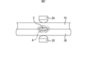
- FIG. 1 is a diagram showing an example of the arrangement of two steel plates including at least one high-strength steel plate and welding electrodes when spot welding is started. As shown in FIG. 1, the steel plates 1A and 1B are overlapped so that the plate surfaces face each other. The superposed steel plates 1A and 1B are sandwiched between the welding electrodes 2A and 2B from above and below, and a predetermined pressure is applied to energize the welding electrodes 2A and 2B.
- FIG. 2 is a diagram schematically showing an example of a nugget formed by spot welding and a heat affected zone.
- FIG. 3 is a diagram illustrating a first example of an energization pattern when energizing a welding electrode.
- spot welding can be performed by the same method as described below.
- the steel plates 1A and 1B and the welding electrodes 2A and 2B are arranged.
- the nugget 3 is formed at the boundary between the steel plates 1 ⁇ / b> A and 1 ⁇ / b> B as shown in FIG. 2.
- the heat affected zone 4 is formed around the nugget 3. Note that at least one of the steel plates 1A and 1B is the high-strength steel plate described above.
- the energization pattern shown in FIG. 3 is as follows.
- the following current is a current flowing between the welding electrode 2A and the welding electrode 2B.
- the current value is gradually increased (upslope) from 0 (zero) until the current value reaches the main welding current I W (kA).
- the main welding is performed with the current value set to the main welding current I W (kA).
- the current value is set to 0 (zero), and the state where the current value is 0 (zero) is maintained after the main welding cooling time (solidification time) t S (msec).
- the current value rear energization current I P (kA) rear energization time the state of t P (msec) retention is set to 0 (zero).
- the holding time t H (msec) shown in FIG. 3 is a time for holding the applied pressure F E (N) after the end of energization, as will be described later.
- the current value becomes the welding current I W (kA)
- the current value without causing 0 increasing from (zero) (up-slope) may immediately present the welding current I W a current value (kA) .
- Pressure F E is lower than "1960 ⁇ h" (N), is possible to suppress the occurrence of defects and cracks in the inside and the heat affected zone 4 of the nugget 3 becomes difficult. As a result, the fracture form of the spot welded joint cannot be improved, and it is difficult to improve the joint strength and reduce the variation in joint strength.
- the tip diameter of the welding electrodes 2A and 2B is preferably about 6 mm to 8 mm.
- h is the plate thickness (mm) of the steel plate.
- the thicknesses of the two steel plates are different (in the example shown in FIG. 2, the thicknesses of the steel plates 1A and 1B are different).
- the arithmetic average value of the plate thicknesses of the two steel plates may be used as “h” in the equation (2).
- spot welding three or more steel plates for example, the sum of the thicknesses of the steel plates is obtained, and the value obtained by dividing the sum into two is used as “h” in equation (2). That's fine.
- This welding current IW and the welding time (time that the flow of the welding current I W) is not particularly limited. Conventionally, a welding current and energization time comparable to the welding current and energization time employed to stably obtain a nugget of a required size may be employed as the main welding current IW and the main welding time.
- the square root of the average value in the main welding time (that is, the effective value of the main welding current) of the value obtained by squaring the main welding current in the main welding time, or the maximum value of the main welding current is the main welding current I W.
- the main welding current I W the main welding current
- the conventional general spot welding equipment can be used as it is.
- the conventional welding electrode can be used as it is also about a welding electrode.
- the power source is not particularly limited, and an AC power source, a DC inverter, an AC inverter, or the like can be used.
- FIG. 4 is a diagram schematically illustrating an example of an aspect in the middle of solidification of a melted portion that solidifies to become a nugget.
- Steel plates 1A while pressing the welding electrodes 2A in pressure F E in 1B, when energized the welding current I W to 2B, the molten portion is formed solidified in the nugget.
- the energization is terminated, the solidification from a molten boundary 3a starts and the post-weld cooling time t S has elapsed, the solidification zone 5 are formed.
- the unsolidified region 6 remains inside the solidified region 5.
- a heat affected zone 4 is formed around the solidification zone 5.
- the unsolidified region 6 is solidified to form a nugget.
- the post-energization is started when the unsolidified region 6 exists. That is, the cooling time t S after the main welding determines the width (length in the plate surface direction) of the solidified region 5 at the start of post-energization.
- the post-weld cooling time t S exceeds 300 (msec)
- the temperature decreases and the solidified region 5 expands. Therefore, long-time post-energization is required in order to obtain the effect of post-energization (effect of improving the structure and improving segregation), which will be described later, at the outer peripheral portion of the nugget 3 and the heat-affected zone 4 around the nugget 3. Therefore, the productivity of the spot welded joint is reduced.
- the post-weld cooling time t S exceeding 300 (msec) is not realistic.
- the cooling time t S after the main welding is less than “7 ⁇ h + 5” (msec)
- the melted portion is not sufficiently solidified and the width of the solidified region 5 is narrowed.
- the post-weld cooling time t S is less than “7 ⁇ h + 5” (msec)
- the prior austenite grains become excessively large, and the toughness of the heat-affected zone 4 is lowered by post-energization described later. Therefore, the effect of post-energization (structure improvement / segregation improvement effect) to be described later cannot be obtained, and it is difficult to sufficiently improve the joint strength.
- the cooling rate of the steel plates 1A and 1B becomes slower as the plate thickness h of the steel plate is larger.
- the cooling time of the steel plates 1A and 1B increases exponentially as the plate thickness h of the steel plate increases.
- the relationship between the cooling time of the steel plates 1A and 1B and the plate thickness h of the steel plate is linearly approximated. can do. Therefore, in the present embodiment, as shown in the equation (3), the lower limit value of the post-weld cooling time t S is expressed in a line format using the plate thickness h of the steel plate.
- a spot welded joint having the same nugget diameter as the weld joint of the first non-normal welding is overlapped with two steel plates having the carbon equivalent and the plate thickness, and cooling after the main welding is performed.
- spot welding was performed by the same method as described above except that no post-energization was performed.
- CTS cross tensile force
- FIG. 5 is a diagram illustrating an example of the relationship between the post-weld cooling time t S and the steel sheet thickness h.
- a plot based on h is indicated by ⁇ .
- the CTS in the first non-normal welding weld joint is improved compared with the CTS in the first normal welding weld joint, but the improvement allowance is less than 20%, or the main welding in the case where it has not improved.
- a plot based on the post-cooling time t S and the plate thickness h of the steel sheet is shown by ⁇ . As shown in FIG. 5, the horizontal axis h (mm) is and the vertical axis is t S (msec). In FIG. 5, the boundary line between ⁇ and ⁇ was determined as a regression curve. From the result, a linear format for determining the lower limit of the equation (3) was obtained.
- the post-weld cooling time t S is set to “7 ⁇ h + 5” (msec) or more and 300 (msec) or less.
- the post-weld cooling time tS is set to “7 ⁇ h + 5” (msec) or more and 250 (msec) or less.
- no current is supplied during the cooling time t S after the main welding.
- the post-weld cooling time t S 0.5 times or less of the current of the welding current I W, the welding electrodes 2A, it may be energized 2B.
- the same value as the thickness h of the steel sheet of the formula (2) is adopted as the thickness h of the steel sheet of the formula (3).
- the post-weld cooling time t S if keep the pressure F E when the main welding, the working efficiency, preferred.
- the pressure F E in the post-weld cooling time t S within a range satisfying the equation (2) may be different from the pressure F E when the main welding.
- the pressing force F E at the rear energization time t P a pressure that satisfies the equation (2).
- the pressure F E is usually (when energizing the main welding current I W) when the main welding, and the melting portion solidifying from the molten boundary, when forming a solidification zone 5 of the shell-like (after the welding If the same as pressure F E at cooling time t S), the working efficiency, preferred.
- the (2) as long as it satisfies the equation, not necessarily the same as in these pressure F E at the rear energization time t P.
- Rear energization current I P Rear energization current I P, the tissue and the segregation of shell-like solidification zone 5, organizations and the segregation of the nugget 3 solidification is completed, a large effect on the organization or segregation of the heat affected zone 4.
- the rear energization current I P is less than "0.66 ⁇ I W" (kA)
- the coagulation zone 5 and the heat-affected zone 4 is heat input is insufficient, the effect of improving the tissue and segregation (tissue ameliorating and segregation Improvement effect) is not obtained.
- the rear energization current I P when the rear energization current I P is in the welding current I W (kA) above, the solidification zone 5 and the heat-affected zone 4 is excessively heated. Furthermore, the solidified zone 5 is remelted. Therefore, the effect of improving the structure and segregation (effect of improving the structure and improving segregation) cannot be obtained. Therefore, in the present embodiment, the rear energization current I P, and less than "0.66 ⁇ I W" (kA) or "I W" (kA).
- the rear energization current I P equal to or less than "0.70 ⁇ I W" (kA) or "0.98 ⁇ I W" (kA) Is preferred.
- an effective value as the welding current I W is a rear energizing current I P is also preferred to employ an effective value.
- a rear energizing current I P is also preferred to employ the maximum value.
- the post-energization current I P is energized to the welding electrodes 2A and 2B for a time that satisfies the formula (5) (post-energization time t P (msec)).
- Patent Document 5 The rear energization time t P, Paragraph [0087] of Patent Document 5, "exceeds 200 msec, the effect of the variation reduction improved and joint strength of the joint strength is reduced, also, productivity is reduced. Is described. That is, Patent Document 5, that which should be a post-energization time t P to 200 (msec) or less is disclosed.
- Patent Document 5 describes a structure inside a nugget. However, there is no description of measures for improving CTS in the case of plug rupture. Therefore, the present inventors conducted a systematic experiment on post-energization for further increasing the CTS in the case of plug rupture.
- a spot welded joint having the same nugget diameter as that of the weld joint of the first non-normal welding is used as the carbon equivalent and the carbon Spot welding was performed in the same manner as described above, except that two steel plates having a plate thickness were overlapped and cooling after main welding and post-energization were not performed.
- the CTS (cross tension force) of the spot welded joint was measured by the method prescribed in JIS Z 3137.
- this spot welded joint is referred to as a first normal welded joint as necessary.
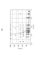
- FIG. 6 shows a rear energization time and t P, a first example of the relationship between the square value of the value obtained by dividing the post-energization current I P in the welding current I W ((I P / I W) 2) FIG.
- the post-energization time t P the post-energization current I P
- the CTS in the first non-normal welding weld joint is improved by 20% or more compared to the CTS in the first normal welding weld joint
- the CTS in the first non-normal welding weld joint is improved as compared with the CTS in the first normal welding weld joint, but the improvement is less than 20%, or the post-energization is not improved.
- a plot based on the time t P , the post-energizing current I P , and the main welding current I W is indicated by ⁇ . As shown in FIG. 6, the horizontal axis is (I P / I W ) 2 and the vertical axis is t P (ms).
- Plug breakage in the spot welded joint occurs in the heat affected zone 4. Therefore, it was estimated that the difference in plug rupture strength was caused by a difference in resistance to propagation of cracks in the heat affected zone 4, that is, a difference in toughness of the heat affected zone 4. Therefore, the concentration distribution of P and S that greatly affects the toughness of the heat affected zone 4 was measured by FE-EPMA. As a result, in the heat-affected zone 4 of the first non-normal weld joint obtained by the conditions indicated by ⁇ in FIG.
- post-energization current I P is solidified zone 5 is required to be a current value which does not melt. That is, it is required that I W> I P.
- I P / I W is an index that determines the amount of heat input (the size of the nugget 3) during post-energization. Therefore, I P / I W is expressed as ⁇ ( ⁇ 1).
- FIG. 7 is a rear energization time t P, is a diagram conceptually illustrating an example of the relationship between the outer peripheral portion and the degree of embrittlement of the heat-affected zone 4 of the nugget 3.
- FIG. 7 conceptually shows how the segregation of P and S is reduced and the toughness is improved.
- the vertical axis indicates the degree of embrittlement due to segregation or insufficient automatic tempering. As the value is below the vertical axis, segregation is reduced and automatic tempering is sufficiently performed to improve toughness.
- the temperature reaches a substantially steady temperature ( ⁇ melting point) by the main welding for forming the welded portion, and the temperature is increased.
- the heat affected zone 4 the temperature is not sufficiently raised by the main welding.
- the temperature of the heat affected zone 4 is lower than the temperature of the outer periphery of the hot nugget 3 immediately after solidification. Therefore, in order to heat-treat the heat-affected zone 4 at a high temperature by post-energization, it takes a long time compared to heat-treating the outer periphery of the nugget 3. This is presumed to be the reason why the result shown in FIG. 6 is obtained.
- the upper limit of the rear energization time t P is not particularly defined, considering the productivity of the spot welded joint, preferably 2000 (msec) or less.
- the pressing force F E (N) when the steel plates 1A and 1B are held under pressure by the welding electrodes 2A and 2B with the holding time t H in the range shown in the formula (9) is, for example, the formula (2). This is the range to be specified.
- the holding time t H affects the structure of the nugget 3 and the heat affected zone 4 and the occurrence of defects and cracks in the nugget 3.
- the holding time t H exceeds 300 (msec)
- the productivity of the spot welded joint is lowered. Therefore, in this embodiment, the holding time t H is set to 300 (msec) or less. It is desirable that the holding time t H be short in order to start air cooling at an early stage and stably obtain the desired effect.
- the holding time t H is usually longer than the retention time set t H. Therefore, it is necessary to set the holding time t H taking this into consideration. Further, the temperature of the nugget 3 also decreases during post-energization. Therefore, the retention time t H a Shortened even shrinkage defects and cracks hardly occur when. Therefore, welding electrodes 2A, 2B and steel plates 1A, if it is possible to spaced immediately from 1B, the holding time t H may be 0 (zero). When the holding time is not set to 0 (zero), the equation (9) becomes the following equation (9a). 0 ⁇ t H ⁇ 300 (9a)
- the steel plates 1A and 1B are overlapped so that the plate surfaces face each other.
- the superposed steel plate 1A and steel plate 1B are sandwiched between the welding electrode 2A and the welding electrode 2B from above and below, and a predetermined pressure is applied to energize.
- a case where two steel plates including at least one high-strength steel plate are spot welded will be described as an example.
- spot welding can be performed by the same method as described below.
- at least two high-strength steel plates can be overlapped and the three or more steel plates can be spot welded.
- high-strength steel plates tend to generate heat during main welding because of their large electrical resistance.
- One of the purposes of pre-energization is to suppress the occurrence of this scattering.
- FIG. 8 is a diagram illustrating a second example of the energization pattern when the welding electrode is energized.
- the current value before flowing current I f (kA) state the previous energization time t f (msec) holding the current value before the supply current I f (kA), performs pre energized.
- the pre-energization time t f (msec) elapses, the current value is set to 0 (zero), and the state where the current value is 0 (zero) is held after the pre-energization cooling time t C (msec).
- the current value is set to the main welding current I W (kA) and the main welding is performed.
- the current value is set to 0 (zero), and the state where the current value is 0 (zero) is maintained after the main welding cooling time (solidification time) t S (msec). If after the welding cooling time t S (msec) has elapsed, the rear electric current I P (kA) the current value, the current value rear energization current I P (kA) rear energization time the state of t P (msec) retention Then, after energization.
- the current value is set to 0 (zero).
- the holding time t H (msec) shown in FIG. 8 is the time for holding the pressurizing force F E (N) after the post-energization is completed, as described in the first example.
- the current value is not immediately changed to the pre-energization current If (kA), but the current value is gradually increased from 0 (zero) until the current value becomes the pre-energization current If (kA). ).
- I W Main welding current (kA) 20 ⁇ t f (11)
- the pre-energization current I f When the pre-energization current I f than the welding current I W, scattered upon before the supply there is a possibility to occur.
- the pre-energization current I f when the pre-energization current I f to less than 0.4 times the main welding current I W, steel plates 1A, the amount of heat given to 1B is not sufficient. Then, the steel plates 1A and 1B cannot be softened, and the gap between the steel plates 1A and 1B cannot be sufficiently reduced by the pressurization described above, and there is a possibility that scattering occurs during the main welding. . From the above, in the present embodiment, the pre-energization current I f, 0.4 times or more of the welding current I W, and less than the welding current I W.
- the pre-energization current I f 0.6 times or more of the welding current I W, that the range of 0.95 times or less of the welding current I W preferable.
- an effective value as the welding current I W is before the supply current I f is also preferred to employ an effective value.
- the maximum value as the welding current I W is before the supply current I f is also preferable to adopt the maximum value.
- the front energization time t f is less than 20 (msec)
- steel plates 1A, the amount of heat given to 1B is not sufficient. Then, the steel plates 1A and 1B cannot be softened, and the gap between the steel plates 1A and 1B cannot be sufficiently reduced by the pressurization described above, and there is a possibility that scattering occurs during the main welding. .
- the welding current I W in the regions shown in the equation (10) even long before the energization time t f, it is possible to suppress the scattering upon before welding occurs. Therefore, the upper limit value before the energization time t f is not particularly defined, considering the productivity of the spot welded joint, preferably 300 (msec) or less.
- the cooling time t C after the pre-energization can be set to a time exceeding 0 (zero). However, if there is no scattering during pre-energization, the cooling time t C after pre-energization can be set to 0 (zero). Further, if the cooling time t C after the pre-energization becomes “200 + 7 ⁇ h” (msec) or more, the steel plates 1A and 1B are excessively cooled, and there is a possibility that the steel plates 1A and 1B become unfamiliar during the main welding. The cooling rate of the steel plates 1A and 1B decreases as the plate thickness h of the steel plate increases.
- the upper limit value of the cooling time t C after the pre-energization is expressed in a line format using the plate thickness h of the steel plate.
- Two steel plates with various plate thicknesses having a carbon equivalent Ceq of 0.3% by mass or more shown in the formula (1) are overlapped, and various aspects are provided in a part or all of the region between the two steel plates.
- a gap was provided at, and spot welding was performed using a servo gun type welding machine in various energization patterns in this order: pre-energization, cooling, main welding, cooling, and post-energization. Then, it was investigated whether or not scattering occurred during the main welding.
- FIG. 9 is a diagram illustrating an example of the relationship between the post-pre-energization cooling time t C and the steel sheet thickness h.
- a plot based on the cooling time after pre-energization t C and the plate thickness h of the steel plate when no scattering occurs in the above-described investigation is indicated by ⁇ .
- a plot based on the cooling time after pre-energization t C and the thickness h of the steel sheet when scatter occurs in the above-described investigation is indicated by ⁇ .
- the horizontal axis h (mm) is and the vertical axis is t C (msec).
- the boundary line between ⁇ and ⁇ was determined as a regression curve. From the result, a line format for determining the upper limit value of the equation (12) was obtained.
- the post-pre-energization cooling time t C is set to 0 (zero) or more and 200 + 7 ⁇ h ”(msec) or less.
- the same value as the thickness h of the steel sheet of the formula (2) is adopted as the thickness h of the steel sheet of the formula (12).
- the pressure F E before after power cooling time t C in a range satisfying the equation (2) may be different from the pressure F E when the pre-energization.
- the equation (12) becomes the following equation (12a). 0 ⁇ t C ⁇ 200 + 7 ⁇ h (12a)
- main welding current I W (Main welding current: I W ) Immediately before or after energizing cooling time t C has elapsed, while maintaining the pressure F E when before the supply as, welding electrodes 2A, between 2B, energized the main welding current I W, it performs the welding.
- the main welding current IW and the main welding time are not particularly limited. Incidentally, the main welding time, if holding the pressure F E when before the supply it, the working efficiency, preferred. However, the pressure F E in the welding time in the range satisfying the equation (2) may be different from the pressure F E when the pre-energization.
- the cooling time t after the main welding is set. to S, 0.5 times or less of the current of the welding current I W may be energized.
- the present post-weld cooling time t S if keep the pressure F E when before the supply and the welding, the working efficiency, preferred.
- the pressure F E in the post-weld cooling time t S within a range satisfying the equation (2) may be different from the pressure F E when before the supply and the welding.
- the expression (13) is the same as the expression (4). That is, the method of determining the post-energization current I P is the same as the first example. As described in the first example, in order to obtain the effect of improving the structure and segregation more reliably, the post-energization current I P is set to “0.70 ⁇ I W ” (kA) or more and “0.98”. ⁇ I W ”(kA) or less is preferable. Further, the rear energization time t P, if keep the pressure F E when before the supply and the welding, the working efficiency, preferred. However, the pressure F E at the rear energization time t P, in a range satisfying the equation (2) may be different from the pressure F E when before the supply and the welding.
- a spot welded joint having the same nugget diameter as that of the second non-normal welded joint is overlapped with two steel plates having the carbon equivalent and the plate thickness, and cooling and post-main welding are performed. Spot welding was performed in the same manner as described above, except that energization was not performed. And the CTS (cross tensile force) of the spot welded joint was measured by the method prescribed in JIS Z 3137. In the following description, this spot welded joint is referred to as a second normal welded joint as necessary.
- FIG. 10 shows a rear energization time t P, a second example of the relationship between the rear energization current I P the value obtained by squaring the value obtained by dividing the welding current I W ((I P / I W) 2)
- FIG. 10 shows a rear energization time t P, a second example of the relationship between the rear energization current I P the value obtained by squaring the value obtained by dividing the welding current I W ((I P / I W) 2)
- the post-energization time t P , post-energization current I P when the CTS in the second non-normal welding weld joint is improved by 20% or more compared to the CTS in the second normal welding weld joint, and a plot in accordance with the present welding current I W in ⁇ . Further, the CTS in the second non-normal welding weld joint is improved as compared with the CTS in the second normal welding weld joint, but the improvement is less than 20%, or the post-energization is not improved.
- a plot based on the time t P , the post-energizing current I P , and the main welding current I W is indicated by ⁇ . As shown in FIG. 10, the horizontal axis is (I P / I W ) 2 and the vertical axis is t P (msec).
- FIG. 10 corresponds to FIG.
- the boundary line between ⁇ and ⁇ was determined as a regression curve (that is, the coefficients A and ⁇ in equation (8) were determined). From the result, the formula (14) was obtained.
- the expression (14) corresponds to the expression (5).
- the coefficient ⁇ is “0.44”.
- the coefficient ⁇ is “0.4”.
- the lower limit of the rear energization time t P is reduced. It is thought that this is because the total heat input to the heat affected zone 4 is increased by performing the pre-energization.
- the upper limit of the rear energization time t P is not particularly defined, considering the productivity of the spot welded joint, preferably 2000 (msec) or less.
- (14) By employing the equation, it is possible to reduce the lower limit of the rear energization time t P.
- the method for determining the holding time t H is the same as in the first example.
- the actual holding time t H is, taking into account the fact that longer than the holding time set t H, it is necessary to set the holding time t H. Further, as described in the first example, the holding time t H may be set to 0 (zero).
- the spot welded joint was formed as in the first and second examples of the spot welding method, an improvement in toughness in the heat affected zone (HAZ) was observed.
- HZ heat affected zone
- the inventors observed the structure of the heat-affected zone of the weld joint for normal welding and the weld joint for non-normal weld with an electron microscope.
- the non-normal welding welded joint in which the CTS is improved by 20% or more of the CTS of the normal welding welded joint, is adopted.
- FIG. 11A is a diagram (photograph) showing an example of a structure of a heat affected zone of the non-normal welding weld joint (the first non-normal welding weld joint).
- FIG. 11B is a figure (photograph) which shows an example of the structure
- tissue of the heat affected zone of the weld joint of the said normal welding welding joint of the said 1st normal welding.
- the iron-based carbide is mainly cementite (Fe 3 C).
- the iron-based carbide is not limited to cementite.
- ⁇ carbide Fe 2.4 C
- other metals such as Mn and Cr may be included in the iron-based carbide.
- the heat input to the heat affected zone 4 is increased, and the highest in the heat affected zone 4
- the ultimate temperature can be increased. Therefore, since the prior austenite grains become large, the apparent martensitic transformation temperature rises. As the apparent martensitic transformation temperature rises, transformation in the heat affected zone 4 occurs at a relatively high temperature in the cooling process after post-energization, and automatic tempering (autotempering) is likely to occur. Thereby, precipitation of fine iron-based carbide is often observed. Thus, the present inventors have found that the precipitation of fine iron carbide in the heat affected zone 4 contributes to the improvement of toughness in the heat affected zone 4.
- the present inventors investigated the precipitation state of iron-based carbides in the heat-affected zone of a plurality of non-normal welded joints where the CTS is improved by 20% or more of the CTS of the welded welded joints. As a result, it was confirmed that if the CTS is a non-normal welding welded joint that improves by 20% or more of the CTS of the normal welded joint, the iron carbide precipitation conditions described below are surely satisfied.
- FIG. 12A is a diagram illustrating an example of iron-based carbide precipitation conditions.
- FIG. 12B is an enlarged view showing a region A in FIG. 12A.
- FIG. 12A is a diagram schematically showing a cross-section cut along the thickness direction of the steel plates 1A and 1B through the center of the welding marks formed on the surfaces of the steel plates 1A and 1B by spot welding.
- a target position (spot position) of the welding electrodes 2A and 2B at the most advanced region
- the contour of the actually formed welding mark can be approximated by a circle, and the center of the circle can be used as the welding mark.
- the iron-based carbide precipitation condition is that 10 or more iron-based carbides having a length of 0.1 ( ⁇ m) or more are precipitated (present).
- the center position of the square region 123 is 100 ( ⁇ m) in a direction perpendicular to the tangent line 121 at the position 120 of the line indicating the end of the nugget 3 from the position 120 of the end of the nugget 3 in the cross section. ) A distant position 102.
- the position 120 of the end portion of the nugget 3 is the position on the line indicating the end portion of the nugget 3 before the spot welding is performed along the plate thickness direction with the center in the plate thickness direction of the spot weld joint as the center. It is a position within a range (within a range indicated by t sum / 4 in FIG. 12A) having a length that is 1 ⁇ 4 times the total plate thickness t sum that is the total thickness of the steel plates 1A and 1B.
- a length including a gap portion between the steel plates 1A and 1B is expressed as a total thickness t sum .
- the total thickness t of the steel plates 1A and 1B before spot welding is calculated without including the length of the gap between the steel plates 1A and 1B. Sum .
- the position of the center in the plate thickness direction of the spot welded joint for example, the center position of the length in the plate thickness direction of the portion passing through the center of the weld mark in the cross section described above can be adopted.
- the length of the longest part of the iron-based carbide for example, the maximum value of the distance between any two points on the line indicating the end of the iron-based carbide in the cross section can be adopted.
- the length of the straight line which passes along the position of the gravity center of iron-based carbide Comprising: The maximum value of the length of the straight line between the two points of the line which comprises the edge part of iron-based carbide is set to iron-based carbide. You may employ
- the square area 123 is defined as described above. This area 123 is an area inside the heat-affected zone 4, and when the plug break occurs in the cross tension test, the crack can be cracked at the initial stage. This is because it occurs.
- At least one of the steel plates 1A and 1B is the above-described high-strength steel plate.
- the case where the two steel plates 1A and 1B were spot-welded was mentioned as an example, and was demonstrated.
- the aforementioned iron-based carbide precipitation conditions can be applied.
- an example of a method for observing iron carbide will be described.
- the cross section is polished.
- an electron micrograph of an area including the square area 123 is taken. From this electron micrograph, the length of the longest part of each iron-based carbide is measured, and the number of iron-based carbides having a longest part length of 0.1 ( ⁇ m) or more is counted. From the number of iron-based carbides, it can be determined whether or not the iron-based carbide precipitation conditions described above are satisfied.
- the above-described square region 123 is referred to as an iron-based carbide counting region as necessary.
- the conditions in the examples are one example of conditions used for confirming the feasibility and effects of the present invention, and the present invention is based on this one example of conditions. It is not limited.
- the present invention can adopt various conditions as long as the object of the present invention is achieved without departing from the gist of the present invention.
- Steel plates A, B, and C shown in Table 1 were prepared.
- Steel plate A is obtained by applying Al plating to the surface of a hot stamped steel plate having a thickness of 2.0 (mm) and a tensile strength of 1470 MPa.
- the steel plate B is obtained by applying Al plating to the surface of a hot stamped steel plate having a thickness of 1.6 (mm) and a tensile strength of 1470 MPa.
- the steel plate C is obtained by applying Zn plating to the surface of a hot stamped steel plate having a thickness of 1.4 (mm) and a tensile strength of 1470 MPa.
- the steel plates D and E shown in Table 1 were prepared.
- the steel plate D is obtained by applying Zn plating to the surface of a cold rolled steel plate having a thickness of 1.2 (mm) and a tensile strength of 1180 MPa.
- the steel plate E is a cold-rolled steel plate having a thickness of 1.4 (mm) and a tensile strength of 980 MPa.
- Ceq shown in Table 1 is a carbon equivalent shown by the formula (1).
- Only C content is shown on account of description.
- Steel plates A to E are steel plates containing the above-described component composition within the above-described upper and lower limits.
- the strength ratio of normal welded joints is based on CTS of spot welded joints (CTS of welded joints of non-normal welds) formed under the welding conditions indicated by numbers 1-1 to 33 and 2-1 to 18.
- CTS of the spot welded joint for normal welding The value obtained by subtracting the CTS of the spot welded joint formed under the same conditions as the welding conditions (CTS of the welded joint for normal welding) is used, except that cooling after the main welding and post-energization are not performed.
- the value obtained by dividing the value by the CTS of the spot welded joint formed by (CTS of the welded joint of non-normal welding) is multiplied by 100.
- FIG. 5, FIG. 6, and FIG. 10 the type of plot is changed depending on whether or not the normal welded joint strength ratio is improved by 20% or more.
- the criterion for determining whether or not the normal weld joint strength ratio has improved by 20% or more is that if the normal weld joint strength ratio has improved by 20% or more, the CTS of the non-normal weld joint and the normal weld weld This is because it can be said that there is a significant difference in the CTS of the joint.
- the length of the longest portion existing in the iron carbide counting region of the spot welded joint formed by performing welding under the welding conditions shown in Tables 2 to 6 is 0.1 ( ⁇ m) or more.
- the number of iron-based carbides was counted with a scanning electron microscope (SEM). The results are shown in the columns of the number of precipitated iron carbides in Tables 7 and 8.
- the target position of the electrode was the center of the welding mark.
- the said 2 steel plate was cut
- the position of the nugget end portion of the cut surface after the polishing, from the center in the plate thickness direction of the spot welded joint to the plate thickness direction 1/8 times the total plate thickness before welding of the two steel plates.
- a region in the heat-affected zone of the cut surface after polishing is located at a position 100 ( ⁇ m) away from this position in a direction perpendicular to the tangent at the position of the line indicating the end of the nugget (line indicating the outline of the nugget). Identified from.
- a copper dome radius type electrode having a radius of curvature of the tip 40 (mm) was used.
- Steel plates A, B, and C were welded at an applied pressure of 5000 (N) using an electrode having a tip diameter of 8 (mm).
- Steel plates D and E were welded at an applied pressure of 3500 (N) using an electrode having a tip diameter of 6 (mm). During pressurization, the applied pressure was not changed.
- the present invention can be used, for example, in industries that use spot welding as a manufacturing technique.
Landscapes
- Engineering & Computer Science (AREA)
- Mechanical Engineering (AREA)
- Resistance Welding (AREA)
- Heat Treatment Of Sheet Steel (AREA)
- Arc Welding In General (AREA)
Abstract
Description
特許文献1には、本通電が終了してから一定時間が経過した後に、テンパー通電を行うことにより、スポット溶接継手(ナゲット部及び熱影響部)を焼鈍して、硬さを低下させる方法が記載されている。 As a method for ensuring strength and toughness in a spot welded joint formed by a plurality of steel plates including at least one steel plate having a tensile strength of 750 MPa or more, there is a two-stage energization method in which post-energization is performed after main energization.
しかし、この方法では、後通電時間を長くすると、ナゲット径が拡大するだけで、組織が通常の溶接と同じになる。 Further,
However, in this method, when the post-energization time is lengthened, the nugget diameter is only enlarged, and the structure becomes the same as that of normal welding.
しかし、この方法では、適用可能な鋼板が限定される。さらに、この方法では、溶接に長時間を要して生産性が低い。
However, in this method, applicable steel plates are limited. Furthermore, this method requires a long time for welding and has low productivity.
しかし、ナゲットの外側で破断する場合には、ナゲットの組織は何の寄与もしないので、ミクロ組織に係る規定は意味がない。
However, in the case of fracture on the outside of the nugget, the structure of the nugget makes no contribution, so the provisions relating to the microstructure are meaningless.
しかし、この方法では、本溶接と後通電との間の時間についての検討が十分になされておらず、継手強度の向上に寄与するものではない。
However, this method does not sufficiently study the time between the main welding and the post-energization, and does not contribute to the improvement of joint strength.
そこで、本発明は、750MPa~2500MPaの鋼板を少なくとも1枚含む複数枚の鋼板により形成されるスポット溶接継手の十字引張力を向上させることを目的とする。 From the above background, spot welded joints formed from a plurality of steel sheets including at least one steel sheet having a tensile strength of 750 MPa to 2500 MPa have a tendency to lack toughness and ensure a sufficiently high cross tensile force. Difficult to do.
Accordingly, an object of the present invention is to improve the cross tensile force of a spot welded joint formed by a plurality of steel plates including at least one steel plate of 750 MPa to 2500 MPa.
Ceq=[C]+[Si]/30+[Mn]/20+2[P]+4[S] ・・・(A)
前記(A)式における[C]、[Si]、[Mn]、[P]、及び[S]は、それぞれC、Si、Mn、P、及びSの各含有量(質量%)である。 The spot welded joint of the present invention is a spot welded joint formed by stacking a plurality of steel plates and performing spot welding, and at least one of the plurality of steel plates has a tensile strength of 750 MPa to 750 MPa. The high-strength steel plate of 2500 MPa, the carbon equivalent Ceq represented by the following formula (A) of the high-strength steel plate is 0.20% by mass to 0.55% by mass, and is formed on the surface of the steel plate by the spot welding. A region in the heat-affected zone in a cross-section cut through the center of the formed welding mark and along the plate thickness direction of the steel plate, wherein the plate thickness direction and plate surface direction of the steel plate are the vertical direction and horizontal direction, respectively. There are 10 or more iron-based carbides having a longest length of 0.1 (μm) or more in a square region having a side of 10 (μm) as a direction, and the center position of the square region is In the cross section The position of the end of the nugget is 100 (μm) away from the position of the line indicating the end of the nugget in the direction perpendicular to the tangent at the position, and the position of the end of the nugget is the end of the nugget The center of the spot welded joint in the plate thickness direction among the positions on the line indicating, and along the plate thickness direction, 1 / of the total plate thickness that is the total value of the plate thickness of the plurality of steel plates The position is within a range having a length four times as long.
Ceq = [C] + [Si] / 30 + [Mn] / 20 + 2 [P] +4 [S] (A)
[C], [Si], [Mn], [P], and [S] in the formula (A) are contents (mass%) of C, Si, Mn, P, and S, respectively.
Ceq=[C]+[Si]/30+[Mn]/20+2[P]+4[S] ・・・(A)
1960×h≦FE≦3920×h ・・・(B)
7×h+5≦tS≦300 ・・・(C)
0.66×IW≦IP<IW ・・・(D)
48/{(IP/IW)2-0.44}≦tP ・・・(E)
0≦tH≦300 ・・・(F)
前記(A)式における[C]、[Si]、[Mn]、[P]、及び[S]は、それぞれC、Si、Mn、P、及びSの各含有量(質量%)であり、前記(B)式及び前記(C)式におけるhは、前記鋼板の板厚(mm)である。 A first example of the spot welding method of the present invention is a spot welding method in which a plurality of steel plates are overlapped and spot welded, and at least one of the plurality of steel plates has a tensile strength of 750 MPa to 750 MPa. The high-strength steel plate of 2500 MPa, the carbon equivalent Ceq represented by the following formula (A) of the high-strength steel plate is 0.20 mass% to 0.55 mass%. A step of performing a main welding in which a main welding current I W (kA) is energized to the welding electrode in a state in which the welding electrode is pressed with a pressing force F E (N) satisfying the following formula (B): When the main welding is completed, the applied pressure F E (N) satisfying the following equation (B) is maintained, and the post-main welding cooling time t S (msec) satisfying the following equation (C) is cooled for cooling the plurality of steel plates. A step of cooling after the main welding and after the main welding When cooling is completed, the post-energization current I P (kA) that satisfies the following formula (D) is maintained by maintaining the applied pressure F E (N) that satisfies the following formula (B), and the post-energization that satisfies the following formula (E). After the time t P (msec), the step of conducting energization after energizing the welding electrode and the post energization are completed, the applied pressure F E (N) that satisfies the equation (B) satisfies the following equation (F): And after releasing the holding time t H (msec), releasing the pressurization with the applied pressure F E (N).
Ceq = [C] + [Si] / 30 + [Mn] / 20 + 2 [P] +4 [S] (A)
1960 × h ≦ F E ≦ 3920 × h (B)
7 × h + 5 ≦ t S ≦ 300 (C)
0.66 × I W ≦ I P <I W (D)
48 / {(I P / I W ) 2 −0.44} ≦ t P (E)
0 ≦ t H ≦ 300 (F)
[C], [Si], [Mn], [P], and [S] in the formula (A) are the contents (mass%) of C, Si, Mn, P, and S, respectively. In the formula (B) and the formula (C), h is the thickness (mm) of the steel plate.
Ceq=[C]+[Si]/30+[Mn]/20+2[P]+4[S] ・・・(A)
1960×h≦FE≦3920×h ・・・(B)
0.40×IW≦If<IW ・・・(C)
20≦tf ・・・(D)
0≦tC<200+7×h ・・・(E)
7×h+5≦tS≦300 ・・・(F)
0.66×IW≦IP<IW ・・・(G)
48/{(IP/IW)2-0.4}≦tP ・・・(H)
0≦tH≦300 ・・・(I)
前記(A)式における[C]、[Si]、[Mn]、[P]、及び[S]は、それぞれC、Si、Mn、P、及びSの各含有量(質量%)であり、前記(B)式、前記(E)式、及び前記(F)式におけるhは、前記鋼板の板厚(mm)である。 A second example of the spot welding method of the present invention is a spot welding method in which a plurality of steel plates are overlapped and spot welded, and at least one of the plurality of steel plates has a tensile strength of 750 MPa to 750 MPa. The high-strength steel plate of 2500 MPa, the carbon equivalent Ceq represented by the following formula (A) of the high-strength steel plate is 0.20 mass% to 0.55 mass%. The pre-energization current I f (kA) satisfying the following formula (C) is satisfied with the welding pressure F E (N) satisfying the following formula (B) by the welding electrode, and the following formula (D) is satisfied. When the pre-energization time t f (msec), the pre-energization process for energizing the welding electrode, and the pre-energization are completed, the pressurizing force F E (N) that satisfies the following formula (B) is maintained, and the following ( E) after the energization before satisfying the cooling time t C (mse ), And performing energization cooled prior to cooling the plurality of steel plates, when the previous energized after cooling ends, to hold the following (B) satisfies the equation pressure F E (N), the welding current I W a (kA), and performing the welding energizing the welding electrode, wherein the main welding is completed, holding the following (B) satisfies the equation pressure F E (N), the following (F) Cooling time after main welding satisfying the equation t S (msec), post-main welding cooling step for cooling the plurality of steel plates, and after the post-main welding cooling, the applied pressure F satisfying the following equation (B) E (N) is maintained, the post-energization current I P (kA) that satisfies the following formula (G), the post-energization time t P (msec) that satisfies the following formula (H), and the post-energization that energizes the welding electrode and performing, when the after power is terminated, the (B) satisfies the equation pressure F E (N) , (I) below after holding time t H (msec) holding satisfying formula, characterized in that and a step of releasing the pressure of the in pressure F E (N).
Ceq = [C] + [Si] / 30 + [Mn] / 20 + 2 [P] +4 [S] (A)
1960 × h ≦ F E ≦ 3920 × h (B)
0.40 × I W ≦ I f <I W (C)
20 ≦ t f (D)
0 ≦ t C <200 + 7 × h (E)
7 × h + 5 ≦ t S ≦ 300 (F)
0.66 × I W ≦ I P <I W (G)
48 / {(I P / I W ) 2 −0.4} ≦ t P (H)
0 ≦ t H ≦ 300 (I)
[C], [Si], [Mn], [P], and [S] in the formula (A) are the contents (mass%) of C, Si, Mn, P, and S, respectively. In the formula (B), the formula (E), and the formula (F), h is the plate thickness (mm) of the steel plate.
ここで、ナゲットとは、溶接電極間の通電で溶融し、その後、凝固した鋼板の部位のことである。熱影響部とは、Ac1点以上、溶融温度未満に加熱された鋼板の部位のことである。 As a result, even if the toughness in the nugget is improved only by improving the toughness in the nugget as in the prior art, the heat-affected zone around the nugget ( It has been found that the low load break caused by HAZ) cannot be sufficiently suppressed.
Here, the nugget is a portion of the steel sheet that is melted by energization between the welding electrodes and then solidified. A heat-affected zone is a portion of a steel sheet heated to a temperature higher than Ac1 and lower than the melting temperature.
まず、スポット溶接に使用する鋼板について説明する。
(鋼種)
鋼種は特に限定されない。例えば、2相組織型(例えば、フェライト中にマルテンサイトを含む組織、フェライト中にベイナイトを含む組織)、加工誘起変態型(フェライト中に残留オーステナイトを含む組織)、焼入れ型(マルテンサイト組織)、微細結晶型(フェライト主体組織)等、何れの型の鋼種でもよい。 [High-strength steel sheet]
First, the steel plate used for spot welding will be described.
(Steel grade)
The steel type is not particularly limited. For example, a two-phase structure type (for example, a structure containing martensite in ferrite, a structure containing bainite in ferrite), a processing-induced transformation type (structure containing residual austenite in ferrite), a quenching type (martensite structure), Any type of steel such as a fine crystal type (ferrite main structure) may be used.
複数枚重ね合せた鋼板のうち少なくとも1枚の鋼板(高強度鋼板)の引張強度は、750MPa~2500MPaとする。通常、高強度鋼板の引張強度が増加するほど、高い継手強度が必要である。スポット溶接継手の十字引張力(CTS)は、590MPa~780MPa級鋼板では、鋼板の強度に比例して増加するが、780MPa以上の強度の鋼板では、減少する。 (Tensile strength)
The tensile strength of at least one steel plate (high-strength steel plate) out of a plurality of stacked steel plates is 750 MPa to 2500 MPa. Usually, the higher the tensile strength of the high-strength steel plate, the higher the joint strength is required. The cross tensile force (CTS) of the spot welded joint increases in proportion to the strength of the steel plate in the 590 MPa to 780 MPa class steel plate, but decreases in the steel plate having a strength of 780 MPa or more.
高強度鋼板の板厚は特に限定されない。例えば、自動車の車体等に一般に用いられている高強度鋼板の板厚(0.5mm~3.2mm)程度であればよい。ただし、高強度鋼板の板厚の増加に伴ってナゲットの周囲での応力集中が増加するので、高強度鋼板の板厚は2.6mm以下が好ましい。 (Thickness)
The plate thickness of the high-strength steel plate is not particularly limited. For example, it may be about the thickness (0.5 mm to 3.2 mm) of a high-strength steel plate generally used for the body of an automobile. However, since the stress concentration around the nugget increases as the plate thickness of the high strength steel plate increases, the plate thickness of the high strength steel plate is preferably 2.6 mm or less.
高強度鋼板の、以下の(1)式で表される炭素当量Ceqは、0.20質量%~0.55質量%の範囲であるのが好ましい。炭素当量Ceqが0.20質量%未満では、引張強度が、前述した高強度鋼板の引張強度の下限値である750MPa以上の引張強度が得られない。一方、炭素当量Ceqが0.55質量%超では、引張強度が、前述した高強度鋼板の引張強度の上限値である2500MPaを超えるので、好ましくない。高強度鋼板と重ね合せる鋼板のCeqは、どのような値でもよい。
Ceq=[C]+[Si]/30+[Mn]/20+2[P]+4[S] ・・・(1)
[C]、[Si]、[Mn]、[P]、及び[S]は、それぞれC、Si、Mn、P、及びSの各含有量(質量%)である。 (Carbon equivalent Ceq)
The carbon equivalent Ceq represented by the following formula (1) of the high-strength steel plate is preferably in the range of 0.20 mass% to 0.55 mass%. When the carbon equivalent Ceq is less than 0.20% by mass, a tensile strength of 750 MPa or more, which is the lower limit value of the tensile strength of the high-strength steel plate described above, cannot be obtained. On the other hand, if the carbon equivalent Ceq is more than 0.55% by mass, the tensile strength exceeds 2500 MPa, which is the upper limit value of the tensile strength of the high-strength steel plate, which is not preferable. Ceq of the steel sheet to be overlapped with the high-strength steel sheet may be any value.
Ceq = [C] + [Si] / 30 + [Mn] / 20 + 2 [P] +4 [S] (1)
[C], [Si], [Mn], [P], and [S] are the contents (mass%) of C, Si, Mn, P, and S, respectively.
前述した高強度鋼板の引張強度(750MPa~2500MPa)を確保できる成分組成を選択すればよい。スポット溶接後の鋼部材が、主として、自動車分野等で使用されることを考慮すれば、高強度鋼板の成分組成は、以下の成分組成が好ましい。なお、以下において、%は質量%を意味する。 (Component composition)
What is necessary is just to select the component composition which can ensure the tensile strength (750 Mpa-2500 Mpa) of the high strength steel plate mentioned above. Considering that the steel member after spot welding is mainly used in the automobile field, etc., the component composition of the high-strength steel sheet is preferably the following component composition. In the following,% means mass%.
Cは、鋼の引張強度を高める元素である。鋼中のCの含有量が多いほど、ナゲットの強度を高めることができる。しかし、鋼中のCの含有量が0.07質量%未満であると、750MPa以上の引張強度を得ることが難しい。一方、鋼中のCの含有量が0.45質量%を超えると、高強度鋼板の加工性が低下する。したがって、高強度鋼板のCの含有量は、0.07質量%~0.45質量%が好ましい。 ((C: 0.07 mass% to 0.45 mass%))
C is an element that increases the tensile strength of steel. The greater the C content in the steel, the higher the strength of the nugget. However, if the C content in the steel is less than 0.07% by mass, it is difficult to obtain a tensile strength of 750 MPa or more. On the other hand, when the content of C in the steel exceeds 0.45% by mass, the workability of the high-strength steel sheet decreases. Therefore, the C content of the high-strength steel plate is preferably 0.07% by mass to 0.45% by mass.
Siは、固溶強化及び組織強化により、鋼の強度を高める元素である。しかし、鋼中のSiの含有量が2.50質量%を超えると、鋼の加工性が低下する。一方、鋼中のSiの含有量を工業的に0.001質量%未満に低減することは技術的に難しい。したがって、高強度鋼板のSiの含有量は、0.001質量%~2.50質量%が好ましい。 ((Si: 0.001% to 2.50% by mass))
Si is an element that increases the strength of steel by solid solution strengthening and structure strengthening. However, if the Si content in the steel exceeds 2.50 mass%, the workability of the steel is lowered. On the other hand, it is technically difficult to industrially reduce the Si content in steel to less than 0.001% by mass. Therefore, the Si content of the high-strength steel plate is preferably 0.001% by mass to 2.50% by mass.
Mnは、鋼の強度を高める元素である。しかし、鋼中のMnの含有量が5.0質量%を超えると、鋼の加工性が劣化する。一方、鋼中のMnの含有量が0.8質量%未満であると、750MPa以上の引張強度を得るのが難しい。したがって、高強度鋼板のMnの含有量は、0.8質量%~5.0質量%が好ましい。 ((Mn: 0.8 mass% to 5.0 mass%))
Mn is an element that increases the strength of steel. However, if the Mn content in the steel exceeds 5.0 mass%, the workability of the steel deteriorates. On the other hand, if the Mn content in the steel is less than 0.8% by mass, it is difficult to obtain a tensile strength of 750 MPa or more. Accordingly, the Mn content of the high-strength steel plate is preferably 0.8% by mass to 5.0% by mass.
Pは、ナゲットを脆化する元素である。鋼中のPの含有量が0.03質量%を超えると、ナゲット内の割れが生じ易くなり、十分に高い継手強度を得ることが難しい。したがって、高強度鋼板のPの含有量は、0.03質量%以下が好ましい。なお、鋼中のPの含有量を0.001質量%未満に低減することは、コストの点で、好ましくない。したがって、高強度鋼板のPの含有量は、0.001質量%以上が好ましい。ただし、高強度鋼板のPの含有量を、0.001質量%未満にしてもよい。 ((P: 0.03 mass% or less))
P is an element that embrittles the nugget. If the P content in the steel exceeds 0.03% by mass, cracks in the nugget are likely to occur, and it is difficult to obtain a sufficiently high joint strength. Therefore, the P content in the high-strength steel plate is preferably 0.03% by mass or less. In addition, it is not preferable in terms of cost to reduce the P content in the steel to less than 0.001% by mass. Therefore, the content of P in the high-strength steel plate is preferably 0.001% by mass or more. However, the P content of the high-strength steel plate may be less than 0.001% by mass.
Sは、ナゲットを脆化する元素である。また、Sは、Mnと結合して粗大なMnSを形成し、鋼の加工性を阻害する元素である。鋼中のSの含有量が0.01質量%を超えると、ナゲット内の割れが生じ易くなることにより、十分に高い継手強度を得ることが難しくなる。さらに、鋼の加工性が低下する。したがって、高強度鋼板のSの含有量は、0.01質量%以下が好ましい。なお、鋼中のSの含有量を0.0001質量%未満に低減することは、コストの点で、好ましくない。したがって、高強度鋼板のSの含有量は、0.0001質量%以上が好ましい。ただし、高強度鋼板のSの含有量を、0.0001質量%未満にしてもよい。 ((S: 0.01% by mass or less))
S is an element that embrittles the nugget. S is an element that binds to Mn to form coarse MnS and inhibits the workability of steel. If the S content in the steel exceeds 0.01% by mass, cracks in the nugget are likely to occur, and it becomes difficult to obtain sufficiently high joint strength. Furthermore, the workability of steel is reduced. Therefore, the content of S in the high-strength steel plate is preferably 0.01% by mass or less. In addition, it is not preferable in terms of cost to reduce the S content in the steel to less than 0.0001% by mass. Therefore, the content of S in the high-strength steel plate is preferably 0.0001% by mass or more. However, the S content of the high-strength steel plate may be less than 0.0001% by mass.
Nは、粗大な窒化物を形成し、鋼の加工性を劣化させる元素である。また、Nは、溶接時のブローホールの発生原因になる元素である。鋼中のNの含有量が0.01質量%を超えると、鋼の加工性の劣化やブローホールの発生が顕著となる。したがって、高強度鋼板のNの含有量は、0.01質量%以下が好ましい。なお、鋼中のNの含有量を0.0005質量%未満に低減することは、コストの点で、好ましくない。したがって、高強度鋼板のNの含有量は、0.0005質量%以上が好ましい。ただし、高強度鋼板のNの含有量を、0.0005質量%未満にしてもよい。 ((N: 0.01% by mass or less))
N is an element that forms coarse nitrides and degrades the workability of steel. N is an element that causes blowholes during welding. When the N content in the steel exceeds 0.01% by mass, deterioration of workability of the steel and occurrence of blowholes become significant. Therefore, the N content of the high-strength steel plate is preferably 0.01% by mass or less. Note that it is not preferable in terms of cost to reduce the N content in the steel to less than 0.0005 mass%. Therefore, the N content of the high-strength steel plate is preferably 0.0005% by mass or more. However, the N content of the high-strength steel plate may be less than 0.0005 mass%.
Oは、酸化物を形成し、鋼の加工性を劣化させる元素である。鋼中のOの含有量が0.01質量%を超えると、鋼の加工性の劣化が顕著となる。したがって、高強度鋼板のOの含有量は0.01質量%以下が好ましい。なお、高強度鋼板のOの含有量を0.0005質量%未満に低減することは、コストの点で、好ましくない。したがって、高強度鋼板のOの含有量は、0.0005質量%以上が好ましい。ただし、高強度鋼板のOの含有量を、0.0005質量%未満にしてもよい。 ((O: 0.01% by mass or less))
O is an element that forms an oxide and degrades the workability of steel. When the content of O in the steel exceeds 0.01% by mass, the workability of the steel is significantly deteriorated. Therefore, the O content of the high-strength steel plate is preferably 0.01% by mass or less. In addition, it is not preferable in terms of cost to reduce the O content of the high-strength steel sheet to less than 0.0005% by mass. Therefore, the O content of the high-strength steel plate is preferably 0.0005% by mass or more. However, the O content of the high-strength steel plate may be less than 0.0005 mass%.
Alは、フェライト安定化元素であり、ベイナイト変態時のセメンタイト析出抑制等の効果がある。このため、鋼組織の制御のために含有されている。また、Alは脱酸材としても機能する。その一方で、Alは酸化しやすい。Alの含有量が1.00質量%を超えていると、介在物が増加することにより、鋼の加工性が劣化しやすくなる。したがって、高強度鋼板のAlの含有量は、1.00質量%以下であることが好ましい。 ((Al: 1.00 mass% or less))
Al is a ferrite stabilizing element and has effects such as suppression of cementite precipitation during bainite transformation. For this reason, it is contained for the control of the steel structure. Al also functions as a deoxidizer. On the other hand, Al is easy to oxidize. If the Al content exceeds 1.00% by mass, inclusions increase, and the workability of the steel tends to deteriorate. Therefore, the Al content of the high-strength steel plate is preferably 1.00% by mass or less.
((Nb:0.005質量%~0.20質量%))
((V :0.005質量%~0.20質量%)) ((Ti: 0.005% to 0.20% by mass))
((Nb: 0.005 mass% to 0.20 mass%))
((V: 0.005 mass% to 0.20 mass%))
Bは、鋼組織を制御して鋼を強化する元素である。しかし、鋼中のBの含有量が0.0001質量%未満であると、添加効果が発現し難い。一方、鋼中のBの含有量が0.01質量%を超えると、添加効果が飽和する。したがって、高強度鋼板のBの含有量は、0.0001質量%~0.01質量%が好ましい。 ((B: 0.0001 mass% to 0.01 mass%))
B is an element that strengthens steel by controlling the steel structure. However, if the content of B in the steel is less than 0.0001% by mass, the effect of addition is hardly exhibited. On the other hand, when the content of B in the steel exceeds 0.01% by mass, the addition effect is saturated. Therefore, the content of B in the high-strength steel plate is preferably 0.0001% by mass to 0.01% by mass.
((Ni:0.01質量%~2.0質量%))
((Cu:0.01質量%~2.0質量%))
((Mo:0.01質量%~0.8質量%)) ((Cr: 0.01% to 2.0% by mass))
((Ni: 0.01 mass% to 2.0 mass%))
((Cu: 0.01% to 2.0% by mass))
((Mo: 0.01% to 0.8% by mass))
高強度鋼板の表面にめっき層が形成されていてもよい。さらに、高強度鋼板と重ね合わせる鋼板の表面にめっき層が形成されていてもよい。めっき層の種類は、例えば、Zn系、Zn-Fe系、Zn-Ni系、Zn-Al系、Zn-Mg系、Pb-Sn系、Sn-Zn系、Al-Si系等が挙げられる。 (Plating)
A plating layer may be formed on the surface of the high-strength steel plate. Furthermore, a plating layer may be formed on the surface of the steel sheet to be overlaid with the high-strength steel sheet. Examples of the plating layer include Zn-based, Zn-Fe-based, Zn-Ni-based, Zn-Al-based, Zn-Mg-based, Pb-Sn-based, Sn-Zn-based, and Al-Si-based.
まず、スポット溶接方法の第1の例を説明する。
[スポット溶接]
図1は、スポット溶接を開始する際の、少なくとも1枚の高強度鋼板を含む2枚の鋼板と溶接電極の配置の一例を示す図である。図1に示すように、鋼板1A、1Bを、板面が互いに向き合うように重ね合わせる。重ね合わせられた鋼板1A、1Bを、上下から溶接電極2A、2Bで挟み、所要の加圧力を加えて、溶接電極2A、2Bを通電する。 <First example of spot welding method>
First, a first example of the spot welding method will be described.
[Spot welding]
FIG. 1 is a diagram showing an example of the arrangement of two steel plates including at least one high-strength steel plate and welding electrodes when spot welding is started. As shown in FIG. 1, the
まず、電流値が本溶接電流IW(kA)になるまで、電流値を0(ゼロ)から漸増(アップスロープ)させる。そして、電流値を本溶接電流IW(kA)にして本溶接を行う。本溶接が終了すると、電流値を0(ゼロ)にし、電流値が0(ゼロ)の状態を本溶接後冷却時間(凝固時間)tS(msec)保持する。本溶接後冷却時間tS(msec)が経過すると、電流値を後通電電流IP(kA)にし、電流値が後通電電流IP(kA)の状態を後通電時間tP(msec)保持し、後通電を行う。後通電時間tP(msec)が経過すると、電流値を0(ゼロ)にする。
なお、図3に示す保持時間tH(msec)は、後述するように、後通電を終了した後、加圧力FE(N)を保持する時間である。
また、電流値が本溶接電流IW(kA)になるまで、電流値を0(ゼロ)から漸増(アップスロープ)させずに、電流値を直ちに本溶接電流IW(kA)にしてもよい。 The energization pattern shown in FIG. 3 is as follows. The following current is a current flowing between the
First, the current value is gradually increased (upslope) from 0 (zero) until the current value reaches the main welding current I W (kA). Then, the main welding is performed with the current value set to the main welding current I W (kA). When the main welding is completed, the current value is set to 0 (zero), and the state where the current value is 0 (zero) is maintained after the main welding cooling time (solidification time) t S (msec). If after the welding cooling time t S (msec) has elapsed, the rear electric current I P (kA) the current value, the current value rear energization current I P (kA) rear energization time the state of t P (msec) retention Then, after energization. When the post-energization time t P (msec) elapses, the current value is set to 0 (zero).
Note that the holding time t H (msec) shown in FIG. 3 is a time for holding the applied pressure F E (N) after the end of energization, as will be described later.
Moreover, until the current value becomes the welding current I W (kA), the current value without causing 0 increasing from (zero) (up-slope), may immediately present the welding current I W a current value (kA) .
重ね合わせた複数枚の鋼板を、溶接電極2A及び2Bにより、以下の(2)式を満たす加圧力FEで加圧しながら、本溶接電流IWを通電する。
1960×h≦FE≦3920×h ・・・(2)
h:鋼板の板厚(mm) (Pressure force: F E )
A superimposed plurality of steel plates were, by
1960 × h ≦ F E ≦ 3920 × h (2)
h: Steel plate thickness (mm)
以上の加圧力FEで鋼板1A、1Bを加圧しながら、溶接電極2A、2Bに、本溶接電流IWを通電し、本溶接を行う。本溶接電流IW及び本溶接時間(本溶接電流IWを流している時間)は特に限定されない。従来、所要の大きさのナゲットを安定して得るのに採用している溶接電流、通電時間と同程度の溶接電流、通電時間を、本溶接電流IW及び本溶接時間として採用すればよい。 (Main welding current: I W )
While applying
本溶接電流IWを、所定の時間、溶接電極2A、2Bに通電し、当該通電が終了した直後、本溶接のとき(本溶接電流IWを通電しているとき)の加圧力FEをそのまま保持しながら、通電を止める。そして、以下の式(3)を満たす本溶接後冷却時間tS(msec)、その状態を保持する。これにより、溶融部を、当該溶融部の外周(すなわち溶融部の他の領域との境界)から凝固させて、内側に未凝固域が残る殻状の凝固域を形成する。なお、以下の説明では、溶融部の他の領域との境界を、必要に応じて溶融境界と称する。
7×h+5≦tS≦300 ・・・(3)
h:鋼板の板厚(mm) (Cooling time after main welding: t S )
The main welding current I W, a predetermined time, the
7 × h + 5 ≦ t S ≦ 300 (3)
h: Steel plate thickness (mm)
鋼板1A、1Bに加圧力FEで加圧しながら溶接電極2A、2Bに本溶接電流IWを通電すると、凝固してナゲットとなる溶融部が形成される。その後、通電が終了すると、溶融境界3aから凝固が始まり、本溶接後冷却時間tSが経過すると、凝固域5が形成される。この時点で、凝固域5の内部には、未凝固域6が残る。凝固域5の周囲には、熱影響部4が形成される。 Immediately after the energization of the welding current I W is finished, solidification of the molten portion begins fusion boundaries. FIG. 4 is a diagram schematically illustrating an example of an aspect in the middle of solidification of a melted portion that solidifies to become a nugget.
図5は、本溶接後冷却時間tSと鋼板の板厚hとの関係の一例を示す図である。
図5において、第1の非通常溶接の溶接継手におけるCTSが、第1の通常溶接の溶接継手におけるCTSに比べ、20%以上向上した場合の、本溶接後冷却時間tS及び鋼板の板厚hに基づくプロットを○で示す。また、第1の非通常溶接の溶接継手におけるCTSが、第1の通常溶接の溶接継手におけるCTSに比べ、向上するが向上代が20%未満の場合、又は向上しなかった場合の、本溶接後冷却時間tS及び鋼板の板厚hに基づくプロットを▲で示す。図5に示すように、横軸h(mm)はであり、縦軸はtS(msec)である。
図5において、○と▲の境界線を回帰曲線として求めた。その結果から、前記(3)式の下限値を定める線形式を得た。 The CTS in the first non-normal welding welded joint was compared with the CTS in the first normal welding welded joint that was not energized afterward.
FIG. 5 is a diagram illustrating an example of the relationship between the post-weld cooling time t S and the steel sheet thickness h.
In FIG. 5, the cooling time t S after the main welding and the plate thickness of the steel sheet when the CTS in the first non-normal welding weld joint is improved by 20% or more compared to the CTS in the first normal welding weld joint. A plot based on h is indicated by ◯. In addition, the CTS in the first non-normal welding weld joint is improved compared with the CTS in the first normal welding weld joint, but the improvement allowance is less than 20%, or the main welding in the case where it has not improved. A plot based on the post-cooling time t S and the plate thickness h of the steel sheet is shown by ▲. As shown in FIG. 5, the horizontal axis h (mm) is and the vertical axis is t S (msec).
In FIG. 5, the boundary line between ○ and ▲ was determined as a regression curve. From the result, a linear format for determining the lower limit of the equation (3) was obtained.
ただし、スポット溶接継手の生産性の低下を避けるため、本溶接後冷却時間tSを、「7×h+5」(msec)以上250(msec)以下にするのがより好ましい。また、凝固域5の形成を促すには、本溶接後冷却時間tSの間、無通電とすることが好ましい。ただし、凝固域5の形成速度と温度を調整するため、本溶接後冷却時間tS、本溶接電流IWの0.5倍以下の電流を、溶接電極2A、2Bに通電してもよい。
なお、(3)式の鋼板の板厚hとして、例えば、前記(2)式の鋼板の板厚hと同じ値を採用する。また、本溶接後冷却時間tS、本溶接のときの加圧力FEをそのまま保持すれば、作業効率上、好ましい。しかしながら、本溶接後冷却時間tSにおける加圧力FEを、前記(2)式を満たす範囲で、本溶接のときの加圧力FEと異ならせてもよい。 From the above, in this embodiment, the post-weld cooling time t S is set to “7 × h + 5” (msec) or more and 300 (msec) or less.
However, in order to avoid a decrease in productivity of the spot welded joint, it is more preferable that the post-weld cooling time tS is set to “7 × h + 5” (msec) or more and 250 (msec) or less. Further, in order to promote the formation of the solidified
For example, the same value as the thickness h of the steel sheet of the formula (2) is adopted as the thickness h of the steel sheet of the formula (3). Further, the post-weld cooling time t S, if keep the pressure F E when the main welding, the working efficiency, preferred. However, the pressure F E in the post-weld cooling time t S, within a range satisfying the equation (2) may be different from the pressure F E when the main welding.
本溶接後冷却時間tSが経過して、所要の幅の凝固域5が形成された直後、本溶接のときの加圧力FE(N)を保持して、以下の(4)式を満たす後通電電流IP(kA)を、以下の(5)式を満たす後通電時間tP(msec)、溶接電極2A、2Bに通電し、後通電を行う。 (Rear electric current: I P, post-energization time: t P)
Immediately after the cooling time t S after the main welding has elapsed and the solidified
IW:本溶接電流(kA)
48/(α2-0.44)≦tP ・・・(5)
α=IP/IW
したがって、(5)式を、以下のように書き換えることができる。
48/(IP/IW)2-0.44)≦tP ・・・(5) 0.66 × I W ≦ I P <I W (4)
I W : Main welding current (kA)
48 / (α 2 −0.44) ≦ t P (5)
α = I P / I W
Therefore, equation (5) can be rewritten as follows.
48 / (I P / I W ) 2 −0.44) ≦ t P (5)
後通電電流IPが「0.66×IW」(kA)未満であると、凝固域5及び熱影響部4は入熱が十分でなく、組織や偏析を改善する効果(組織改善・偏析改善の効果)が得られない。 Rear energization current I P, the tissue and the segregation of shell-
When the rear energization current I P is less than "0.66 × I W" (kA), the
よって、本実施形態では、後通電電流IPを、「0.66×IW」(kA)以上「IW」(kA)未満とする。ただし、組織や偏析を改善する効果をより確実に得るために、後通電電流IPを、「0.70×IW」(kA)以上「0.98×IW」(kA)以下にするのが好ましい。なお、本溶接電流IWとして実効値を採用する場合には、後通電電流IPも実効値を採用するのが好ましい。また、本溶接電流IWとして最大値を採用する場合には、後通電電流IPも最大値を採用するのが好ましい。 On the other hand, when the rear energization current I P is in the welding current I W (kA) above, the
Therefore, in the present embodiment, the rear energization current I P, and less than "0.66 × I W" (kA) or "I W" (kA). However, in order to obtain the effect of improving the tissue and segregation more reliably, the rear energization current I P, equal to or less than "0.70 × I W" (kA) or "0.98 × I W" (kA) Is preferred. In the case of employing an effective value as the welding current I W is a rear energizing current I P is also preferred to employ an effective value. Furthermore, when adopting the maximum value as the welding current I W is a rear energizing current I P is also preferred to employ the maximum value.
図6は、後通電時間tPと、後通電電流IPを本溶接電流IWで除した値の自乗した値((IP/IW)2)との関係の第1の例を示す図である。
図6において、第1の非通常溶接の溶接継手におけるCTSが、第1の通常溶接の溶接継手におけるCTSに比べ、20%以上向上した場合の、後通電時間tP、後通電電流IP、及び本溶接電流IWに基づくプロットを○で示す。また、第1の非通常溶接の溶接継手におけるCTSが、第1の通常溶接の溶接継手におけるCTSに比べ、向上するが向上代が20%未満の場合、又は向上しなかった場合の、後通電時間tP、後通電電流IP、及び本溶接電流IWに基づくプロットを▲で示す。図6に示すように、横軸は(IP/IW)2であり、縦軸はtP(ms)である。 The CTS in the first non-normal welding welded joint was compared with the CTS in the first normal welding welded joint that was not energized afterward.
Figure 6 shows a rear energization time and t P, a first example of the relationship between the square value of the value obtained by dividing the post-energization current I P in the welding current I W ((I P / I W) 2) FIG.
In FIG. 6, the post-energization time t P , the post-energization current I P , when the CTS in the first non-normal welding weld joint is improved by 20% or more compared to the CTS in the first normal welding weld joint, and a plot based on the welding current I W in ○. In addition, the CTS in the first non-normal welding weld joint is improved as compared with the CTS in the first normal welding weld joint, but the improvement is less than 20%, or the post-energization is not improved. A plot based on the time t P , the post-energizing current I P , and the main welding current I W is indicated by ▲. As shown in FIG. 6, the horizontal axis is (I P / I W ) 2 and the vertical axis is t P (ms).
Q∝(α2-β)×tP ・・・(6)
α=IP/IW Heat generated by post-energization is proportional to the square of the rear energization current I P. Therefore, in FIG. 6, (I P / I W ) 2 is adopted on the horizontal axis. Further, part of the heat generated by the post-energization escapes to the
Q∝ (α 2 −β) × t P (6)
α = I P / I W
したがって、スポット溶接部の靭性を改善するための条件は、以下の(7)式を変形して(8)式となる。
A<(α2-β)×tP ・・・(7)
A/(α2-β)<tP ・・・(8) And in order to reduce the segregation of P and S in the outer peripheral part of the
Therefore, the condition for improving the toughness of the spot welded portion is obtained by modifying the following equation (7) into equation (8).
A <(α 2 −β) × t P (7)
A / (α 2 −β) <t P (8)
以上の条件で後通電を行った後、相互に重ね合わせた鋼板1A、1Bを、溶接電極2A、2Bで、以下の(9)式で規定する保持時間tH(msec)、加圧保持した後、加圧を解放する。
0≦tH≦300 ・・・(9) (Retention time: t H )
After post-energization was performed under the above conditions, the
0 ≦ t H ≦ 300 (9)
また、後通電のときにもナゲット3の温度が低下する。このため、保持時間tHを短くした場合でも収縮欠陥や割れが生じにくい。したがって、溶接電極2A、2Bを鋼板1A、1Bから即時に離隔させることが可能であれば、保持時間tHを0(ゼロ)にしてもよい。保持時間を0(ゼロ)にしない場合には、(9)式は、以下の(9a)式になる。
0<tH≦300 ・・・(9a) In the existing welding machine, because the delay in operation of the welding gun, the actual holding time t H is usually longer than the retention time set t H. Therefore, it is necessary to set the holding time t H taking this into consideration.
Further, the temperature of the
0 <t H ≦ 300 (9a)
次に、スポット溶接方法の第2の例を説明する。スポット溶接方法の第1の例では、本溶接と後通電との2回の通電を行う場合を例に挙げて説明した。これに対し、スポット溶接方法の第2の例では、前通電を行った後に、本溶接と後通電とを行う場合を例に挙げて説明する。このように、本例は、第1の例に対し、前通電が追加されたことと、前通電が追加されたことにより、前記(5)式を変更することが可能になったこととが異なる。したがって、本例の説明において、第1の例と同一の部分については、図1~図7に付した符号と同一の符号を付す等して詳細な説明を省略する。 <Second example of spot welding method>
Next, a second example of the spot welding method will be described. In the first example of the spot welding method, the case where two energizations of main welding and post energization are performed has been described as an example. On the other hand, in the second example of the spot welding method, a case where main welding and post-energization are performed after pre-energization will be described as an example. Thus, in this example, the pre-energization is added to the first example, and the addition of the pre-energization makes it possible to change the equation (5). Different. Therefore, in the description of this example, the same parts as those in the first example are denoted by the same reference numerals as those in FIGS. 1 to 7, and detailed description thereof is omitted.
まず、電流値を前通電電流If(kA)にし、電流値が前通電電流If(kA)の状態を前通電時間tf(msec)保持し、前通電を行う。前通電時間tf(msec)が経過すると、電流値を0(ゼロ)にし、電流値が0(ゼロ)の状態を前通電後冷却時間tC(msec)保持する。前通電後冷却時間tCが経過すると、電流値を本溶接電流IW(kA)にして本溶接を行う。本溶接が終了すると、電流値を0(ゼロ)にし、電流値が0(ゼロ)の状態を本溶接後冷却時間(凝固時間)tS(msec)保持する。本溶接後冷却時間tS(msec)が経過すると、電流値を後通電電流IP(kA)にし、電流値が後通電電流IP(kA)の状態を後通電時間tP(msec)保持し、後通電を行う。後通電時間tP(msec)が経過すると、電流値を0(ゼロ)にする。なお、図8に示す保持時間tH(msec)は、第1の例で説明したように、後通電を終了した後、加圧力FE(N)を保持する時間である。また、前通電の開始時に、電流値を直ちに前通電電流If(kA)にせず、電流値が前通電電流If(kA)になるまで、電流値を0(ゼロ)から漸増(アップスロープ)させてもよい。 FIG. 8 is a diagram illustrating a second example of the energization pattern when the welding electrode is energized.
First, the current value before flowing current I f (kA), state the previous energization time t f (msec) holding the current value before the supply current I f (kA), performs pre energized. When the pre-energization time t f (msec) elapses, the current value is set to 0 (zero), and the state where the current value is 0 (zero) is held after the pre-energization cooling time t C (msec). When the cooling time t C elapses after pre-energization, the current value is set to the main welding current I W (kA) and the main welding is performed. When the main welding is completed, the current value is set to 0 (zero), and the state where the current value is 0 (zero) is maintained after the main welding cooling time (solidification time) t S (msec). If after the welding cooling time t S (msec) has elapsed, the rear electric current I P (kA) the current value, the current value rear energization current I P (kA) rear energization time the state of t P (msec) retention Then, after energization. When the post-energization time t P (msec) elapses, the current value is set to 0 (zero). Note that the holding time t H (msec) shown in FIG. 8 is the time for holding the pressurizing force F E (N) after the post-energization is completed, as described in the first example. Also, at the start of pre-energization, the current value is not immediately changed to the pre-energization current If (kA), but the current value is gradually increased from 0 (zero) until the current value becomes the pre-energization current If (kA). ).
重ね合わせた複数枚の鋼板を、溶接電極2A及び2Bにより、前記(2)式を満たす加圧力FEで加圧しながら、前通電電流Ifを通電する。前通電においては、隣り合う2枚の鋼板1A、1Bの隙間を抑制するために、重ね合わせた複数枚の鋼板を加圧する。本実施形態では、前通電における加圧力FEの範囲を、本溶接及び後通電における加圧力FEの範囲と同じ範囲にすることにより、作業効率を高めるようにする。 (Pressure force: F E )
A superimposed plurality of steel plates were, by
以上の加圧力FEで鋼板1A、1Bを加圧しながら、溶接電極2A、2B間に、以下の(10)式を満たす前通電電流If(kA)を、以下の(11)式を満たす前通電時間tf(msec)、通電し、前通電を行う。 (Pre-energization current: I f , pre-energization time: t f )
While pressing the
IW:本溶接電流(kA)
20≦tf ・・・(11) 0.40 × I W ≦ I f <I W (10)
I W : Main welding current (kA)
20 ≦ t f (11)
以上のことから、本実施形態では、前通電電流Ifを、本溶接電流IWの0.4倍以上、本溶接電流IW未満とする。ただし、散りの発生をより確実に抑制するために、前通電電流Ifを、本溶接電流IWの0.6倍以上、本溶接電流IWの0.95倍以下の範囲にするのが好ましい。
なお、本溶接電流IWとして実効値を採用する場合には、前通電電流Ifも実効値を採用するのが好ましい。また、本溶接電流IWとして最大値を採用する場合には、前通電電流Ifも最大値を採用するのが好ましい。 When the pre-energization current I f than the welding current I W, scattered upon before the supply there is a possibility to occur. On the other hand, when the pre-energization current I f to less than 0.4 times the main welding current I W, steel plates 1A, the amount of heat given to 1B is not sufficient. Then, the
From the above, in the present embodiment, the pre-energization current I f, 0.4 times or more of the welding current I W, and less than the welding current I W. However, in order to more reliably suppress the occurrence of scattering, the pre-energization current I f, 0.6 times or more of the welding current I W, that the range of 0.95 times or less of the welding current I W preferable.
In the case of employing an effective value as the welding current I W is before the supply current I f is also preferred to employ an effective value. Furthermore, when adopting the maximum value as the welding current I W is before the supply current I f is also preferable to adopt the maximum value.
前記(10)式に示す範囲の本溶接電流IWであれば、前通電時間tfが長くても、前溶接の際に散りが発生することを抑制することができる。したがって、前通電時間tfの上限値は、特に定めないが、スポット溶接継手の生産性を考慮すれば、300(msec)以下が好ましい。 When the front energization time t f is less than 20 (msec),
If the welding current I W in the regions shown in the equation (10), even long before the energization time t f, it is possible to suppress the scattering upon before welding occurs. Therefore, the upper limit value before the energization time t f is not particularly defined, considering the productivity of the spot welded joint, preferably 300 (msec) or less.
前通電電流Ifを、前通電時間tf、通電し、当該通電が終了した直後、前通電のとき(前通電電流Ifを通電しているとき)の加圧力FEをそのまま保持しながら、通電を止める。そして、以下の(12)式を満たす前通電後冷却時間tC(msec)、その状態を保持する。
0≦tC<200+7×h ・・・(12)
h:鋼板の板厚(mm) (Cooling time after pre-energization: t C )
The pre-energization current I f, before energization time t f, energized, immediately after the energization is terminated, while maintaining the time before the supply of the pressure F E of (when energized a pre-energization current I f) as Turn off the power. And the pre-energization cooling time t C (msec) that satisfies the following expression (12) is maintained for that state.
0 ≦ t C <200 + 7 × h (12)
h: Steel plate thickness (mm)
図9において、前述した調査において散りが発生しなかった場合の、前通電後冷却時間tC及び鋼板の板厚hに基づくプロットを○で示す。また、前述した調査において散りが発生した場合の、前通電後冷却時間tC及び鋼板の板厚hに基づくプロットを▲で示す。図9に示すように、横軸h(mm)はであり、縦軸はtC(msec)である。
図9において、○と▲の境界線を回帰曲線として求めた。その結果から、前記(12)式の上限値を定める線形式を得た。 FIG. 9 is a diagram illustrating an example of the relationship between the post-pre-energization cooling time t C and the steel sheet thickness h.
In FIG. 9, a plot based on the cooling time after pre-energization t C and the plate thickness h of the steel plate when no scattering occurs in the above-described investigation is indicated by ◯. In addition, a plot based on the cooling time after pre-energization t C and the thickness h of the steel sheet when scatter occurs in the above-described investigation is indicated by ▲. As shown in FIG. 9, the horizontal axis h (mm) is and the vertical axis is t C (msec).
In FIG. 9, the boundary line between ○ and ▲ was determined as a regression curve. From the result, a line format for determining the upper limit value of the equation (12) was obtained.
なお、(12)式の鋼板の板厚hとして、例えば、前記(2)式の鋼板の板厚hと同じ値を採用する。また、前通電後冷却時間tCに、前通電のときの加圧力FEをそのまま保持すれば、作業効率上、好ましい。しかしながら、前通電後冷却時間tCにおける加圧力FEを、前記(2)式を満たす範囲で、前通電のときの加圧力FEと異ならせてもよい。
また、前通電後冷却時間tCを確保する場合には、(12)式は、以下の(12a)式になる。
0<tC<200+7×h ・・・(12a) From the above, in this embodiment, the post-pre-energization cooling time t C is set to 0 (zero) or more and 200 + 7 × h ”(msec) or less.
For example, the same value as the thickness h of the steel sheet of the formula (2) is adopted as the thickness h of the steel sheet of the formula (12). Also, before after power cooling time t C, if keep the pressure F E when before the supply, the working efficiency, it preferred. However, the pressure F E before after power cooling time t C, in a range satisfying the equation (2) may be different from the pressure F E when the pre-energization.
Further, when the cooling time t C after pre-energization is ensured, the equation (12) becomes the following equation (12a).
0 <t C <200 + 7 × h (12a)
前通電後冷却時間tCが経過した直後、前通電のときの加圧力FEをそのまま保持しながら、溶接電極2A、2B間に、本溶接電流IWを通電し、本溶接を行う。第1の例で説明したように、本溶接電流IW及び本溶接時間(本溶接電流IWを通電している時間)は特に限定されない。なお、本溶接時間に、前通電のときの加圧力FEをそのまま保持すれば、作業効率上、好ましい。しかしながら、本溶接時間における加圧力FEを、前記(2)式を満たす範囲で、前通電のときの加圧力FEと異ならせてもよい。 (Main welding current: I W )
Immediately before or after energizing cooling time t C has elapsed, while maintaining the pressure F E when before the supply as,
本溶接電流IWを、所定の時間、通電し、当該通電が終了した直後、前通電及び本溶接のときの加圧力FEをそのまま保持しながら、通電を止める。そして、前記(3)式を満たす本溶接後冷却時間tS(msec)、その状態を保持する。
本溶接後冷却時間tSを決定する方法は、第1の例と同じである。なお、第1の例で説明したように、スポット溶接継手の生産性の低下を避けるため、本溶接後冷却時間tSを、「7×h+5」(msec)以上250(msec)以下にするのがより好ましい。また、凝固域5の形成を促すには、本溶接後冷却時間tSの間、無通電とすることが好ましいが、凝固域5の形成速度と温度を調整するため、本溶接後冷却時間tSに、本溶接電流IWの0.5倍以下の電流を通電してもよい。また、本溶接後冷却時間tSに、前通電及び本溶接のときの加圧力FEをそのまま保持すれば、作業効率上、好ましい。しかしながら、本溶接後冷却時間tSにおける加圧力FEを、前記(2)式を満たす範囲で、前通電及び本溶接のときの加圧力FEと異ならせてもよい。 (Cooling time after main welding: t S )
The main welding current I W, a predetermined time, energizing, immediately after the energization is terminated, while keep the pressure F E when before the supply and the welding stop energization. Then, the (3) cooling time after the weld which satisfies the formula t S (msec), and holds the state.
Method of determining the post-weld cooling time t S is the same as the first example. As described in the first example, the cooling time after main welding t S is set to “7 × h + 5” (msec) or more and 250 (msec) or less in order to avoid a decrease in productivity of the spot welded joint. Is more preferable. Further, in order to promote the formation of the solidified
本溶接後冷却時間tSが経過して、所要の幅の凝固域5が形成された直後、前通電及び本溶接のときの加圧力FE(N)を保持して、以下の(13)式を満たす後通電電流IP(kA)を、以下の(14)式を満たす後通電時間tP(msec)、通電し、後通電を行う。 (Rear electric current: I P, post-energization time: t P)
Immediately after the cooling time t S after the main welding has elapsed and the solidified
IW:本溶接電流(kA)
48/(α2-0.4)≦tP ・・・(14)
α=IP/IW
したがって、(14)式は、以下の式のように書き換えることができる。
48/(IP/IW)2-0.4)≦tP ・・・(14) 0.66 × I W ≦ I P <I W (13)
I W : Main welding current (kA)
48 / (α 2 −0.4) ≦ t P (14)
α = I P / I W
Therefore, the equation (14) can be rewritten as the following equation.
48 / (I P / I W ) 2 −0.4) ≦ t P (14)
図10は、後通電時間tPと、後通電電流IPを本溶接電流IWで除した値を自乗した値((IP/IW)2)との関係の第2の例を示す図である。 The CTS in the second non-normal welding welded joint was compared with the CTS in the second normal welding welded joint that was not energized afterward.
Figure 10 shows a rear energization time t P, a second example of the relationship between the rear energization current I P the value obtained by squaring the value obtained by dividing the welding current I W ((I P / I W) 2) FIG.
(14)式は、前記(5)式に対応する。前記(5)式では係数βは「0.44」である。これに対し、(14)式では係数βは「0.4」である。したがって、第1の例に比べて第2の例の方が、後通電時間tPの下限値が小さくなる。前通電を行うことにより熱影響部4に対する総入熱量が大きくなるためであると考えられる。 FIG. 10 corresponds to FIG. As in the first example, in FIG. 10, the boundary line between ◯ and ▲ was determined as a regression curve (that is, the coefficients A and β in equation (8) were determined). From the result, the formula (14) was obtained.
The expression (14) corresponds to the expression (5). In the equation (5), the coefficient β is “0.44”. On the other hand, in the equation (14), the coefficient β is “0.4”. Thus, towards the second example than in the first example, the lower limit of the rear energization time t P is reduced. It is thought that this is because the total heat input to the heat affected
また、本例のように、(14)式を採用すれば、後通電時間tPの下限値を小さくすることができる。ただし、例えば、前通電を行う場合と行わない場合の後通電時間tPを統一することにより、後通電時間tPの設定の間違いを防止するために、本例においても(14)式ではなく、前記(5)式を採用してもよい。 As described in the first example, when the post-energization time t P is less than 200 (msec), the selection range of α (= I P / I W ) described above becomes narrow (see FIG. 10). reference). Therefore, the post-energization time t P, preferably to the 200 (msec) or more, more preferably to 400 (msec) or more. The upper limit of the rear energization time t P is not particularly defined, considering the productivity of the spot welded joint, preferably 2000 (msec) or less.
Moreover, as in this example, (14) By employing the equation, it is possible to reduce the lower limit of the rear energization time t P. However, for example, by unifying the energization time t P after the case of not performing the case of performing the pre-energizing, in order to prevent mistakes rear energization time t P of the setting, rather than also (14) in this example The equation (5) may be adopted.
以上の条件で後通電を行った後、相互に重ね合わせた鋼板1A、1Bを、溶接電極2A、2Bで、前記(9)式で規定される保持時間tH(msec)、加圧保持した後、加圧を解放する。
0≦tH≦300 ・・・(9) (Retention time: t H )
After post-energization was performed under the above conditions, the
0 ≦ t H ≦ 300 (9)
次に、本実施形態のスポット溶接継手について説明する。なお、以下の説明では、前記第1の通常溶接の溶接継手と前記第2の通常溶接の溶接継手を総称する場合、これらを必要に応じて通常溶接の溶接継手と称する。また、前記第1の非通常溶接の溶接継手と前記第2の非通常溶接の溶接継手を総称する場合、これらを必要に応じて非通常溶接の溶接継手と称する。 <Spot welded joint>
Next, the spot welded joint of this embodiment will be described. In the following description, when the first normal-welded weld joint and the second normal-welded weld joint are collectively referred to, they are referred to as normal-welded weld joints as necessary. In addition, when the first non-normal welding weld joint and the second non-normal welding weld joint are collectively referred to, they are referred to as non-normal welding weld joints as necessary.
図12Aは、スポット溶接により鋼板1A、1Bの表面に形成された溶接痕の中心を通り、且つ、鋼板1A、1Bの板厚方向に沿って切った断面を模式的に示す図である。溶接痕の中心としては、例えば、溶接電極2A、2Bの(最先端の領域の)狙い位置(打点位置)を採用することができる。また、実際に形成された溶接痕の輪郭を円で近似し、当該円の中心を溶接痕とすることができる。 FIG. 12A is a diagram illustrating an example of iron-based carbide precipitation conditions. FIG. 12B is an enlarged view showing a region A in FIG. 12A.
FIG. 12A is a diagram schematically showing a cross-section cut along the thickness direction of the
ここで、正方形の領域123の中心の位置は、前記断面において、ナゲット3の端部の位置120から、ナゲット3の端部を示す線の当該位置120における接線121に垂直な方向に100(μm)離れた位置102である。 It is a region in the heat affected
Here, the center position of the
また、鉄系炭化物の最長部の長さとしては、例えば、前記断面において、鉄系炭化物の端部を示す線の任意の2点間の距離の最大値を採用することができる。また、前記断面において、鉄系炭化物の重心の位置を通る直線の長さであって、鉄系炭化物の端部を構成する線の2点間の直線の長さの最大値を、鉄系炭化物の最長部の長さとして採用してもよい。 As the position of the center in the plate thickness direction of the spot welded joint, for example, the center position of the length in the plate thickness direction of the portion passing through the center of the weld mark in the cross section described above can be adopted.
Further, as the length of the longest part of the iron-based carbide, for example, the maximum value of the distance between any two points on the line indicating the end of the iron-based carbide in the cross section can be adopted. Moreover, in the said cross section, it is the length of the straight line which passes along the position of the gravity center of iron-based carbide, Comprising: The maximum value of the length of the straight line between the two points of the line which comprises the edge part of iron-based carbide is set to iron-based carbide. You may employ | adopt as the length of the longest part of.
なお、表1に示すCeqは、(1)式で示される炭素当量である。また、表1では、表記の都合上、Cの含有量のみを示す。鋼板A~Eは、前述した成分組成を、前述した上下限の範囲内で含有する鋼板である。 Steel plates A, B, and C shown in Table 1 were prepared. Steel plate A is obtained by applying Al plating to the surface of a hot stamped steel plate having a thickness of 2.0 (mm) and a tensile strength of 1470 MPa. The steel plate B is obtained by applying Al plating to the surface of a hot stamped steel plate having a thickness of 1.6 (mm) and a tensile strength of 1470 MPa. The steel plate C is obtained by applying Zn plating to the surface of a hot stamped steel plate having a thickness of 1.4 (mm) and a tensile strength of 1470 MPa. Moreover, the steel plates D and E shown in Table 1 were prepared. The steel plate D is obtained by applying Zn plating to the surface of a cold rolled steel plate having a thickness of 1.2 (mm) and a tensile strength of 1180 MPa. The steel plate E is a cold-rolled steel plate having a thickness of 1.4 (mm) and a tensile strength of 980 MPa.
In addition, Ceq shown in Table 1 is a carbon equivalent shown by the formula (1). Moreover, in Table 1, only C content is shown on account of description. Steel plates A to E are steel plates containing the above-described component composition within the above-described upper and lower limits.

前記鉄系炭化物計数領域を得るために、電極の狙い位置を溶接痕の中心とした。そして、当該溶接痕の中心を通り、且つ、2枚の鋼板の板厚方向に沿うように、当該2枚の鋼板を切断し、切断面を研磨した。この研磨後の切断面を走査型電子顕微鏡で観察し、前記鉄系炭化物計数領域を確定した。まず、前記研磨後の切断面のナゲットの端部の位置であって、スポット溶接継手の板厚方向の中心から板厚方向に、2枚の鋼板の溶接前の総板厚の1/8倍の長さだけ離れた2つの位置のうちの1つを特定した。この位置から、ナゲットの端部を示す線(ナゲットの輪郭を示す線)の当該位置における接線に垂直な方向に100(μm)離れた位置を、前記研磨後の切断面の熱影響部内の領域から特定した。そして、この位置を中心とする領域であって、2枚の鋼板の板厚方向、板面方向をそれぞれ縦方向、横方向とする一辺が10μmの正方形の領域を前記鉄系炭化物計数領域とした。また、鉄系炭化物の端部を示す線の任意の2点間の距離の最大値を最長部とした。 Further, the length of the longest portion existing in the iron carbide counting region of the spot welded joint formed by performing welding under the welding conditions shown in Tables 2 to 6 is 0.1 (μm) or more. The number of iron-based carbides was counted with a scanning electron microscope (SEM). The results are shown in the columns of the number of precipitated iron carbides in Tables 7 and 8.
In order to obtain the iron-based carbide counting region, the target position of the electrode was the center of the welding mark. And the said 2 steel plate was cut | disconnected and the cut surface was grind | polished so that it might pass along the center of the said welding trace and the thickness direction of two steel plates. The cut surface after the polishing was observed with a scanning electron microscope to determine the iron-based carbide counting region. First, the position of the nugget end portion of the cut surface after the polishing, from the center in the plate thickness direction of the spot welded joint to the plate thickness direction, 1/8 times the total plate thickness before welding of the two steel plates. One of two locations separated by a length of. A region in the heat-affected zone of the cut surface after polishing is located at a position 100 (μm) away from this position in a direction perpendicular to the tangent at the position of the line indicating the end of the nugget (line indicating the outline of the nugget). Identified from. And it is an area | region centering on this position, Comprising: The square area | region whose one side which makes the board | plate thickness direction of a 2 steel plate and plate | board surface direction a vertical direction and a horizontal direction is respectively 10 micrometers is made into the said iron-type carbide count area | region. . The maximum value of the distance between any two points on the line indicating the end of the iron-based carbide was taken as the longest part.


なお、鋼板中のPの含有量が0.03質量%を超える場合と、Sの含有量が0.01質量%を超える場合には、溶接条件に関わらず、20%以上の通常溶接継手強度比が得られなかった。また、炭素当量Ceq及びその他の成分組成については、前述した範囲でない場合に、高強度鋼板の特性(引張強度、加工性等)が低下することが確認された。 As shown in Tables 7 and 8, numbers 1-4 to 8, 1-12 to 18, 1-20 to 29, 1-31 to 33, 2-5 to 7, 2-12, 2-13 In the invention example, the requirements specified as described above are satisfied (see Tables 7 and 8). Therefore, a welded joint having high joint strength (normal weld joint strength ratio of 20% or more) compared to the joint strength of a welded joint by ordinary spot welding is obtained.
When the P content in the steel sheet exceeds 0.03% by mass and when the S content exceeds 0.01% by mass, the strength of the normal welded joint is 20% or more regardless of welding conditions. The ratio was not obtained. In addition, with respect to the carbon equivalent Ceq and other component compositions, it was confirmed that the properties (tensile strength, workability, etc.) of the high-strength steel plate were lowered when the carbon equivalent Ceq and other component compositions were not within the above-described ranges.
Claims (3)
- 複数枚の鋼板を重ね合わせてスポット溶接することにより形成されるスポット溶接継手であって、
前記複数枚の鋼板のうち少なくとも1枚の鋼板は、引張強度が750MPa~2500MPaの高強度鋼板であり、
前記高強度鋼板の下記(A)式で表される炭素当量Ceqは、0.20質量%~0.55質量%であり、
前記スポット溶接により前記鋼板の表面に形成された溶接痕の中心を通り、且つ、前記鋼板の板厚方向に沿って切った断面における熱影響部内の領域であって、前記鋼板の板厚方向、板面方向をそれぞれ縦方向、横方向とする一辺が10(μm)の正方形の領域内に、最長部の長さが0.1(μm)以上である鉄系炭化物が10個以上存在し、
前記正方形の領域の中心の位置は、前記断面において、ナゲットの端部の位置から、当該ナゲットの端部を示す線の当該位置における接線に垂直な方向に100(μm)離れた位置であり、
前記ナゲットの端部の位置は、当該ナゲットの端部を示す線上の位置のうち、前記スポット溶接継手の前記板厚方向の中心を中心とし、前記板厚方向に沿って、前記複数枚の鋼板の板厚の合計値である総板厚の1/4倍の長さを有する範囲内にある位置であることを特徴とするスポット溶接継手。
Ceq=[C]+[Si]/30+[Mn]/20+2[P]+4[S] ・・・(A)
前記(A)式における[C]、[Si]、[Mn]、[P]、及び[S]は、それぞれC、Si、Mn、P、及びSの各含有量(質量%)である。 It is a spot welded joint formed by spot welding with overlapping multiple steel plates,
At least one of the plurality of steel plates is a high strength steel plate having a tensile strength of 750 MPa to 2500 MPa,
The carbon equivalent Ceq represented by the following formula (A) of the high-strength steel plate is 0.20% by mass to 0.55% by mass,
Through the center of the welding mark formed on the surface of the steel plate by the spot welding, and in the heat affected zone in the cross section cut along the plate thickness direction of the steel plate, the plate thickness direction of the steel plate, 10 or more iron-based carbides having a longest length of 0.1 (μm) or more exist in a square region having a side of 10 (μm) each having a plate surface direction as a vertical direction and a horizontal direction,
The position of the center of the square region is a position away from the position of the end of the nugget in the cross section by 100 (μm) in a direction perpendicular to the tangent at the position of the line indicating the end of the nugget,
The position of the end of the nugget is centered on the center in the plate thickness direction of the spot welded joint among the positions on the line indicating the end of the nugget, and the plurality of steel plates along the plate thickness direction. A spot welded joint having a position within a range having a length that is 1/4 times the total thickness, which is the total value of the thicknesses.
Ceq = [C] + [Si] / 30 + [Mn] / 20 + 2 [P] +4 [S] (A)
[C], [Si], [Mn], [P], and [S] in the formula (A) are contents (mass%) of C, Si, Mn, P, and S, respectively. - 複数枚の鋼板を重ね合わせてスポット溶接するスポット溶接方法であって、
前記複数枚の鋼板のうち少なくとも1枚の鋼板は、引張強度が750MPa~2500MPaの高強度鋼板であり、
前記高強度鋼板の下記(A)式で表される炭素当量Ceqは、0.20質量%~0.55質量%であり、
前記重ね合わせた複数枚の鋼板を、溶接電極により、下記(B)式を満たす加圧力FE(N)で加圧した状態で、本溶接電流IW(kA)を、前記溶接電極に通電する本溶接を行う工程と、
前記本溶接が終了すると、下記(B)式を満たす加圧力FE(N)を保持して、下記(C)式を満たす本溶接後冷却時間tS(msec)、前記複数枚の鋼板を冷却する本溶接後冷却を行う工程と、
前記本溶接後冷却が終了すると、下記(B)式を満たす加圧力FE(N)を保持して、下記(D)式を満たす後通電電流IP(kA)を、下記(E)式を満たす後通電時間tP(msec)、前記溶接電極に通電する後通電を行う工程と、
前記後通電が終了すると、前記(B)式を満たす加圧力FE(N)を、下記(F)式を満たす保持時間tH(msec)保持した後、前記加圧力FE(N)での加圧を解放する工程と、を有することを特徴とするスポット溶接方法。
Ceq=[C]+[Si]/30+[Mn]/20+2[P]+4[S] ・・・(A)
1960×h≦FE≦3920×h ・・・(B)
7×h+5≦tS≦300 ・・・(C)
0.66×IW≦IP<IW ・・・(D)
48/{(IP/IW)2-0.44}≦tP ・・・(E)
0≦tH≦300 ・・・(F)
前記(A)式における[C]、[Si]、[Mn]、[P]、及び[S]は、それぞれC、Si、Mn、P、及びSの各含有量(質量%)であり、前記(B)式及び前記(C)式におけるhは、前記鋼板の板厚(mm)である。 A spot welding method in which a plurality of steel plates are overlapped and spot welded,
At least one of the plurality of steel plates is a high strength steel plate having a tensile strength of 750 MPa to 2500 MPa,
The carbon equivalent Ceq represented by the following formula (A) of the high-strength steel plate is 0.20% by mass to 0.55% by mass,
The welding electrode I is energized with a main welding current I W (kA) in a state in which the plurality of stacked steel plates are pressurized with a welding electrode with a pressure F E (N) satisfying the following expression (B). Performing a main welding process,
When the main welding is completed, the post-main-cooling cooling time t S (msec) satisfying the following expression (C) is maintained while maintaining the applied pressure F E (N) satisfying the following expression (B), and the plurality of steel sheets are combined. A process of cooling after the main welding to cool,
When the cooling after the main welding is finished, the post-energization current I P (kA) that satisfies the following formula (D) is maintained by maintaining the applied pressure F E (N) that satisfies the following formula (B). A post-energization time t P (msec) that satisfies the following step of energizing the welding electrode;
When the post-energization ends, the pressurizing force F E (N) satisfying the formula (B) is held for the holding time t H (msec) satisfying the following formula (F), and then the pressurizing force F E (N) And a step of releasing the pressurization of the spot welding method.
Ceq = [C] + [Si] / 30 + [Mn] / 20 + 2 [P] +4 [S] (A)
1960 × h ≦ F E ≦ 3920 × h (B)
7 × h + 5 ≦ t S ≦ 300 (C)
0.66 × I W ≦ I P <I W (D)
48 / {(I P / I W ) 2 −0.44} ≦ t P (E)
0 ≦ t H ≦ 300 (F)
[C], [Si], [Mn], [P], and [S] in the formula (A) are the contents (mass%) of C, Si, Mn, P, and S, respectively. In the formula (B) and the formula (C), h is the thickness (mm) of the steel plate. - 複数枚の鋼板を重ね合わせてスポット溶接するスポット溶接方法であって、
前記複数枚の鋼板のうち少なくとも1枚の鋼板は、引張強度が750MPa~2500MPaの高強度鋼板であり、
前記高強度鋼板の下記(A)式で表される炭素当量Ceqは、0.20質量%~0.55質量%であり、
前記重ね合わせた複数枚の鋼板を、溶接電極により、下記(B)式を満たす加圧力FE(N)で加圧した状態で、下記(C)式を満たす前通電電流If(kA)を、下記(D)式を満たす前通電時間tf(msec)、前記溶接電極に通電する前通電を行う工程と、
前記前通電が終了すると、下記(B)式を満たす加圧力FE(N)を保持して、下記(E)式を満たす前通電後冷却時間tC(msec)、前記複数枚の鋼板を冷却する前通電後冷却を行う工程と、
前記前通電後冷却が終了すると、下記(B)式を満たす加圧力FE(N)を保持して、本溶接電流IW(kA)を、前記溶接電極に通電する本溶接を行う工程と、
前記本溶接が終了すると、下記(B)式を満たす加圧力FE(N)を保持して、下記(F)式を満たす本溶接後冷却時間tS(msec)、前記複数枚の鋼板を冷却する本溶接後冷却を行う工程と、
前記本溶接後冷却が終了すると、下記(B)式を満たす加圧力FE(N)を保持して、下記(G)式を満たす後通電電流IP(kA)を、下記(H)式を満たす後通電時間tP(msec)、前記溶接電極に通電する後通電を行う工程と、
前記後通電が終了すると、前記(B)式を満たす加圧力FE(N)を、下記(I)式を満たす保持時間tH(msec)保持した後、前記加圧力FE(N)での加圧を解放する工程と、を有することを特徴とするスポット溶接方法。
Ceq=[C]+[Si]/30+[Mn]/20+2[P]+4[S] ・・・(A)
1960×h≦FE≦3920×h ・・・(B)
0.40×IW≦If<IW ・・・(C)
20≦tf ・・・(D)
0≦tC<200+7×h ・・・(E)
7×h+5≦tS≦300 ・・・(F)
0.66×IW≦IP<IW ・・・(G)
48/{(IP/IW)2-0.4}≦tP ・・・(H)
0≦tH≦300 ・・・(I)
前記(A)式における[C]、[Si]、[Mn]、[P]、及び[S]は、それぞれC、Si、Mn、P、及びSの各含有量(質量%)であり、前記(B)式、前記(E)式、及び前記(F)式におけるhは、前記鋼板の板厚(mm)である。
A spot welding method in which a plurality of steel plates are overlapped and spot welded,
At least one of the plurality of steel plates is a high strength steel plate having a tensile strength of 750 MPa to 2500 MPa,
The carbon equivalent Ceq represented by the following formula (A) of the high-strength steel plate is 0.20% by mass to 0.55% by mass,
The pre-energization current If (kA) satisfying the following formula (C) in a state where the plurality of the stacked steel plates are pressed by the welding electrode with the applied pressure F E (N) satisfying the following formula (B). A pre-energization time t f (msec) that satisfies the following equation (D), a step of performing pre-energization to energize the welding electrode,
When the pre-energization is completed, the applied pressure F E (N) satisfying the following equation (B) is maintained, the cooling time after pre-energization satisfying the following equation (E) t C (msec), and the plurality of steel plates A step of cooling after energization before cooling;
When the cooling after the pre-energization is completed, a process of performing a main welding in which the welding force I W (kA) is energized to the welding electrode while maintaining the applied pressure F E (N) satisfying the following equation (B): ,
When the main welding is completed, the post-main-cooling cooling time t S (msec) satisfying the following expression (F) is maintained while maintaining the applied pressure F E (N) satisfying the following expression (B), and the plurality of steel sheets are combined. A process of cooling after the main welding to cool,
When the cooling after the main welding is finished, the post-energization current I P (kA) that satisfies the following equation (G) is maintained by maintaining the applied pressure F E (N) that satisfies the following equation (B). A post-energization time t P (msec) that satisfies the following step of energizing the welding electrode;
When the post-energization ends, the pressurizing force F E (N) satisfying the formula (B) is held for the holding time t H (msec) satisfying the following formula (I), and then the pressurizing force F E (N) And a step of releasing the pressurization of the spot welding method.
Ceq = [C] + [Si] / 30 + [Mn] / 20 + 2 [P] +4 [S] (A)
1960 × h ≦ F E ≦ 3920 × h (B)
0.40 × I W ≦ I f <I W (C)
20 ≦ t f (D)
0 ≦ t C <200 + 7 × h (E)
7 × h + 5 ≦ t S ≦ 300 (F)
0.66 × I W ≦ I P <I W (G)
48 / {(I P / I W ) 2 −0.4} ≦ t P (H)
0 ≦ t H ≦ 300 (I)
[C], [Si], [Mn], [P], and [S] in the formula (A) are the contents (mass%) of C, Si, Mn, P, and S, respectively. In the formula (B), the formula (E), and the formula (F), h is the plate thickness (mm) of the steel plate.
Priority Applications (13)
| Application Number | Priority Date | Filing Date | Title |
|---|---|---|---|
| ES14807362.0T ES2663500T3 (en) | 2013-06-05 | 2014-06-02 | Spot welded joint structure and spot welding method |
| EP14807362.0A EP3006154B1 (en) | 2013-06-05 | 2014-06-02 | Spot welded joined structure and spot welding method |
| KR1020157032845A KR101805284B1 (en) | 2013-06-05 | 2014-06-02 | Spot welded joint and spot welding method |
| CA2912591A CA2912591C (en) | 2013-06-05 | 2014-06-02 | Spot-welded joint and spot welding method |
| RU2015155581A RU2633414C2 (en) | 2013-06-05 | 2014-06-02 | Spot-weld joint and method for spot welding |
| MX2015015832A MX2015015832A (en) | 2013-06-05 | 2014-06-02 | Spot welded joint and spot welding method. |
| MYPI2015704012A MY183966A (en) | 2013-06-05 | 2014-06-02 | Spot-welded joint and spot welding method |
| JP2015521438A JP5987982B2 (en) | 2013-06-05 | 2014-06-02 | Spot welding joint and spot welding method |
| BR112015028782A BR112015028782A2 (en) | 2013-06-05 | 2014-06-02 | spot welded joint and welding method |
| US14/889,111 US20160082543A1 (en) | 2013-06-05 | 2014-06-02 | Spot-welded joint and spot welding method |
| CN201480030432.5A CN105263663B (en) | 2013-06-05 | 2014-06-02 | Tack-weld and spot welding method |
| ZA2015/08065A ZA201508065B (en) | 2013-06-05 | 2015-10-30 | Spot welded joint and spot welding method |
| US16/145,696 US11027361B2 (en) | 2013-06-05 | 2018-09-28 | Spot-welded joint and spot welding method |
Applications Claiming Priority (2)
| Application Number | Priority Date | Filing Date | Title |
|---|---|---|---|
| JP2013-118886 | 2013-06-05 | ||
| JP2013118886 | 2013-06-05 |
Related Child Applications (2)
| Application Number | Title | Priority Date | Filing Date |
|---|---|---|---|
| US14/889,111 A-371-Of-International US20160082543A1 (en) | 2013-06-05 | 2014-06-02 | Spot-welded joint and spot welding method |
| US16/145,696 Division US11027361B2 (en) | 2013-06-05 | 2018-09-28 | Spot-welded joint and spot welding method |
Publications (1)
| Publication Number | Publication Date |
|---|---|
| WO2014196499A1 true WO2014196499A1 (en) | 2014-12-11 |
Family
ID=52008141
Family Applications (1)
| Application Number | Title | Priority Date | Filing Date |
|---|---|---|---|
| PCT/JP2014/064616 WO2014196499A1 (en) | 2013-06-05 | 2014-06-02 | Spot welded joint and spot welding method |
Country Status (14)
| Country | Link |
|---|---|
| US (2) | US20160082543A1 (en) |
| EP (1) | EP3006154B1 (en) |
| JP (1) | JP5987982B2 (en) |
| KR (1) | KR101805284B1 (en) |
| CN (1) | CN105263663B (en) |
| BR (1) | BR112015028782A2 (en) |
| CA (1) | CA2912591C (en) |
| ES (1) | ES2663500T3 (en) |
| MX (1) | MX2015015832A (en) |
| MY (1) | MY183966A (en) |
| RU (1) | RU2633414C2 (en) |
| TW (1) | TWI587954B (en) |
| WO (1) | WO2014196499A1 (en) |
| ZA (1) | ZA201508065B (en) |
Cited By (9)
| Publication number | Priority date | Publication date | Assignee | Title |
|---|---|---|---|---|
| JP2017047476A (en) * | 2015-09-03 | 2017-03-09 | 新日鐵住金株式会社 | Spot welding method |
| JP2017047475A (en) * | 2015-09-03 | 2017-03-09 | 新日鐵住金株式会社 | Spot welding method |
| WO2017038981A1 (en) * | 2015-09-03 | 2017-03-09 | 新日鐵住金株式会社 | Spot welding method |
| WO2017073793A1 (en) * | 2015-10-30 | 2017-05-04 | 新日鐵住金株式会社 | Spot welding electrode having movable pressing member and spot welding method using same |
| CN107921572A (en) * | 2015-08-27 | 2018-04-17 | 杰富意钢铁株式会社 | The manufacture method of resistance spot welding method and welded unit |
| CN108136535A (en) * | 2015-10-16 | 2018-06-08 | 新日铁住金株式会社 | Tack-weld and spot welding method |
| WO2019054116A1 (en) * | 2017-09-13 | 2019-03-21 | Jfeスチール株式会社 | Resistance spot welding method |
| WO2021210541A1 (en) * | 2020-04-15 | 2021-10-21 | 株式会社神戸製鋼所 | Method for producing resistance-welded member |
| WO2022215103A1 (en) * | 2021-04-05 | 2022-10-13 | 日本製鉄株式会社 | Resistance spot welded joint and method for manufacturing resistance spot welded joint |
Families Citing this family (21)
| Publication number | Priority date | Publication date | Assignee | Title |
|---|---|---|---|---|
| WO2013161937A1 (en) * | 2012-04-25 | 2013-10-31 | 新日鐵住金株式会社 | Spot-welding joint |
| MX2015015832A (en) * | 2013-06-05 | 2016-03-04 | Nippon Steel & Sumitomo Metal Corp | Spot welded joint and spot welding method. |
| CN107000109B (en) * | 2014-12-01 | 2021-09-10 | 杰富意钢铁株式会社 | Resistance spot welding method |
| US10933488B2 (en) * | 2015-10-21 | 2021-03-02 | Nippon Steel Corporation | Method of resistance spot welding |
| DE102016208026A1 (en) * | 2016-05-10 | 2017-11-16 | Volkswagen Aktiengesellschaft | Welding electrode, method for resistance spot welding and motor vehicle |
| EP3470161A4 (en) * | 2016-06-09 | 2019-07-24 | JFE Steel Corporation | Resistance spot welding method |
| JP6055154B1 (en) * | 2016-08-29 | 2016-12-27 | オリジン電気株式会社 | Bonding member manufacturing method and bonding member manufacturing apparatus |
| BR112019028089B1 (en) * | 2017-06-30 | 2023-01-10 | Aperam | METHOD FOR WELDING TWO STEEL SHEETS |
| JP6963282B2 (en) * | 2018-04-20 | 2021-11-05 | 株式会社神戸製鋼所 | Aluminum material resistance spot welding joints and aluminum material resistance spot welding method |
| JP6658993B1 (en) * | 2018-06-29 | 2020-03-04 | Jfeスチール株式会社 | Resistance spot welding method and method for manufacturing welded member |
| CN111683787A (en) * | 2018-08-01 | 2020-09-18 | 深圳配天智能技术研究院有限公司 | Automatic welding set, calibration subassembly and calibration system of welding set |
| CN109079304A (en) * | 2018-10-10 | 2018-12-25 | 鞍钢股份有限公司 | A kind of spot-welding technology method of carbon equivalent high cold-rolled biphase steel |
| JP7267770B2 (en) * | 2019-02-25 | 2023-05-02 | 株式会社神戸製鋼所 | Method for joining plated steel sheets and joining structure |
| EP3978178A4 (en) * | 2019-05-28 | 2022-08-03 | JFE Steel Corporation | Resistance spot welding unit and resistance spot welding method, and resistance spot welded joint and method for manufacturing resistance spot welded joint |
| EP4116455A4 (en) * | 2020-03-05 | 2024-02-21 | Jfe Steel Corp | Resistance spot welding method and manufacturing method for resistance spot welded joint |
| CN112695249A (en) * | 2020-12-11 | 2021-04-23 | 马鞍山钢铁股份有限公司 | 1800MPa grade double-sided non-uniform-thickness aluminum-silicon coating hot forming steel and resistance spot welding method thereof |
| CN112695250A (en) * | 2020-12-11 | 2021-04-23 | 马鞍山钢铁股份有限公司 | 1500 MPa-grade double-sided non-uniform-thickness aluminum-silicon coating hot forming steel and resistance spot welding method thereof |
| CN112620906B (en) * | 2020-12-11 | 2022-08-16 | 马鞍山钢铁股份有限公司 | Method for improving corrosion resistance of resistance spot welding spot of 1500 MPa-grade hot forming steel |
| CN112846470A (en) * | 2021-01-05 | 2021-05-28 | 中国科学院上海光学精密机械研究所 | Resistance spot welding method containing ultra-strong hot forming steel plate matching |
| CN113442458A (en) * | 2021-06-30 | 2021-09-28 | 高宜张 | Umbrella belt processing technology |
| CN113441826A (en) * | 2021-07-16 | 2021-09-28 | 上海交通大学 | Spot welding process for inhibiting liquid metal brittle cracks of galvanized high-strength steel resistance spot welding joint |
Citations (9)
| Publication number | Priority date | Publication date | Assignee | Title |
|---|---|---|---|---|
| JP2002103048A (en) | 2000-09-29 | 2002-04-09 | Nippon Steel Corp | Method for spot welding of high strength steel plate |
| JP2009125801A (en) | 2007-11-28 | 2009-06-11 | Nissan Motor Co Ltd | Welding method |
| JP2010059451A (en) | 2008-09-02 | 2010-03-18 | Sumitomo Metal Ind Ltd | Welded joint and manufacturing method therefor |
| JP2010115706A (en) | 2008-10-16 | 2010-05-27 | Jfe Steel Corp | Resistance spot welding method for high-strength steel sheet |
| JP2011005544A (en) | 2009-05-27 | 2011-01-13 | Nippon Steel Corp | Spot welding method for high-strength steel sheet |
| WO2011025015A1 (en) | 2009-08-31 | 2011-03-03 | 新日本製鐵株式会社 | Spot-welded joint and spot welding method |
| JP2011177794A (en) * | 2011-05-18 | 2011-09-15 | Okuchi Kensan Kk | Resistance welding method |
| JP2012192455A (en) * | 2012-05-30 | 2012-10-11 | Nippon Steel Corp | Spot welding method for high-strength steel sheet |
| US20130020288A1 (en) * | 2011-07-21 | 2013-01-24 | Ford Global Technologies, Llc | System and Method of Welding a Workpiece |
Family Cites Families (24)
| Publication number | Priority date | Publication date | Assignee | Title |
|---|---|---|---|---|
| US4072843A (en) * | 1976-06-16 | 1978-02-07 | General Dynamics Corporation | Apparatus and method for weld bonding |
| DE3005083A1 (en) * | 1980-02-12 | 1981-08-20 | GME Entwicklungsgesellschaft für Maschinenbau und Elektronik mbH, 7320 Göppingen | METHOD FOR THE PRODUCTION OF ROUND JOINTED WELDED FRAME |
| GB2249981B (en) * | 1990-10-08 | 1994-05-18 | Sg Kabushiki Kaisha | Method for checking a spot welded portion and spot welding machine |
| US8058584B2 (en) * | 2007-03-30 | 2011-11-15 | Nissan Motor Co., Ltd. | Bonding method of dissimilar materials made from metals and bonding structure thereof |
| US8263234B2 (en) * | 2007-12-05 | 2012-09-11 | Honda Motor Co., Ltd. | High-strength steel sheet, strength member for vehicles using the same, and method for producing strength member for vehicles |
| JP5151615B2 (en) * | 2008-03-28 | 2013-02-27 | 新日鐵住金株式会社 | Spot welding method for high strength steel sheet |
| US8450634B2 (en) * | 2008-09-23 | 2013-05-28 | Honda Motor Co., Ltd. | Resistance welding apparatus and resistance welding method |
| JP5415896B2 (en) * | 2009-01-29 | 2014-02-12 | Jfeスチール株式会社 | Indirect spot welding method |
| US9498840B2 (en) * | 2009-07-31 | 2016-11-22 | Neturen Co., Ltd. | Welding structural part and welding method of the same |
| JP5468350B2 (en) * | 2009-10-23 | 2014-04-09 | マツダ株式会社 | Dissimilar metal plate joining method |
| JP2011152574A (en) * | 2010-01-28 | 2011-08-11 | Honda Motor Co Ltd | Resistance welding method |
| DE112010005316T5 (en) * | 2010-04-07 | 2012-12-20 | GM Global Technology Operations LLC (n. d. Ges. d. Staates Delaware) | A method of controlling the indentation depth of an electrode into a metal substrate during welding |
| US9969026B2 (en) * | 2011-08-25 | 2018-05-15 | GM Global Technology Operations LLC | Weld schedule for resistance spot welding of aluminum alloy workpieces |
| JP5333560B2 (en) * | 2011-10-18 | 2013-11-06 | Jfeスチール株式会社 | Resistance spot welding method and resistance spot welding joint of high strength steel plate |
| JP5267640B2 (en) * | 2011-11-25 | 2013-08-21 | Jfeスチール株式会社 | Evaluation method for resistance spot welded joints |
| CN102581459B (en) * | 2012-03-07 | 2014-06-25 | 上海交通大学 | Electric resistance welding method for variable-thickness ultra-high strength hot formed steel plate and low-carbon steel plate |
| IN2015DN00600A (en) * | 2012-09-24 | 2015-06-26 | Nippon Steel & Sumitomo Metal Corp | |
| JP5609966B2 (en) * | 2012-12-28 | 2014-10-22 | Jfeスチール株式会社 | Resistance spot welding method |
| MX2015015832A (en) * | 2013-06-05 | 2016-03-04 | Nippon Steel & Sumitomo Metal Corp | Spot welded joint and spot welding method. |
| US9737956B2 (en) * | 2013-06-14 | 2017-08-22 | GM Global Technology Operations LLC | Resistance spot welding thin gauge steels |
| DE102013108563A1 (en) * | 2013-08-08 | 2015-02-12 | Thyssenkrupp Steel Europe Ag | Method and device for resistance welding of sandwich panels |
| US9999938B2 (en) * | 2013-08-23 | 2018-06-19 | GM Global Technology Operations LLC | Multi-step direct welding of an aluminum-based workpiece to a steel workpiece |
| DE102013112436A1 (en) * | 2013-11-12 | 2015-05-13 | Thyssenkrupp Ag | Multi-stage resistance welding of sandwich panels |
| CN106255566B (en) * | 2014-05-07 | 2018-12-18 | 新日铁住金株式会社 | Spot welding method |
-
2014
- 2014-06-02 MX MX2015015832A patent/MX2015015832A/en unknown
- 2014-06-02 EP EP14807362.0A patent/EP3006154B1/en active Active
- 2014-06-02 CA CA2912591A patent/CA2912591C/en not_active Expired - Fee Related
- 2014-06-02 WO PCT/JP2014/064616 patent/WO2014196499A1/en active Application Filing
- 2014-06-02 RU RU2015155581A patent/RU2633414C2/en active
- 2014-06-02 JP JP2015521438A patent/JP5987982B2/en active Active
- 2014-06-02 US US14/889,111 patent/US20160082543A1/en not_active Abandoned
- 2014-06-02 ES ES14807362.0T patent/ES2663500T3/en active Active
- 2014-06-02 MY MYPI2015704012A patent/MY183966A/en unknown
- 2014-06-02 KR KR1020157032845A patent/KR101805284B1/en active IP Right Grant
- 2014-06-02 CN CN201480030432.5A patent/CN105263663B/en active Active
- 2014-06-02 BR BR112015028782A patent/BR112015028782A2/en active Search and Examination
- 2014-06-04 TW TW103119395A patent/TWI587954B/en not_active IP Right Cessation
-
2015
- 2015-10-30 ZA ZA2015/08065A patent/ZA201508065B/en unknown
-
2018
- 2018-09-28 US US16/145,696 patent/US11027361B2/en active Active
Patent Citations (9)
| Publication number | Priority date | Publication date | Assignee | Title |
|---|---|---|---|---|
| JP2002103048A (en) | 2000-09-29 | 2002-04-09 | Nippon Steel Corp | Method for spot welding of high strength steel plate |
| JP2009125801A (en) | 2007-11-28 | 2009-06-11 | Nissan Motor Co Ltd | Welding method |
| JP2010059451A (en) | 2008-09-02 | 2010-03-18 | Sumitomo Metal Ind Ltd | Welded joint and manufacturing method therefor |
| JP2010115706A (en) | 2008-10-16 | 2010-05-27 | Jfe Steel Corp | Resistance spot welding method for high-strength steel sheet |
| JP2011005544A (en) | 2009-05-27 | 2011-01-13 | Nippon Steel Corp | Spot welding method for high-strength steel sheet |
| WO2011025015A1 (en) | 2009-08-31 | 2011-03-03 | 新日本製鐵株式会社 | Spot-welded joint and spot welding method |
| JP2011177794A (en) * | 2011-05-18 | 2011-09-15 | Okuchi Kensan Kk | Resistance welding method |
| US20130020288A1 (en) * | 2011-07-21 | 2013-01-24 | Ford Global Technologies, Llc | System and Method of Welding a Workpiece |
| JP2012192455A (en) * | 2012-05-30 | 2012-10-11 | Nippon Steel Corp | Spot welding method for high-strength steel sheet |
Non-Patent Citations (1)
| Title |
|---|
| See also references of EP3006154A4 |
Cited By (27)
| Publication number | Priority date | Publication date | Assignee | Title |
|---|---|---|---|---|
| CN107921572A (en) * | 2015-08-27 | 2018-04-17 | 杰富意钢铁株式会社 | The manufacture method of resistance spot welding method and welded unit |
| CN107921572B (en) * | 2015-08-27 | 2021-03-05 | 杰富意钢铁株式会社 | Resistance spot welding method and method for manufacturing welded member |
| US10835986B2 (en) | 2015-08-27 | 2020-11-17 | Jfe Steel Corporation | Resistance spot welding method and welded member production method |
| EP3342524A4 (en) * | 2015-08-27 | 2019-05-01 | JFE Steel Corporation | Resistance spot welding method and method for manufacturing welded member |
| EP3345711A4 (en) * | 2015-09-03 | 2019-05-01 | Nippon Steel & Sumitomo Metal Corporation | Spot welding method |
| JP2017047475A (en) * | 2015-09-03 | 2017-03-09 | 新日鐵住金株式会社 | Spot welding method |
| WO2017038981A1 (en) * | 2015-09-03 | 2017-03-09 | 新日鐵住金株式会社 | Spot welding method |
| US11007598B2 (en) | 2015-09-03 | 2021-05-18 | Nippon Steel Corporation | Spot welding method |
| JP2017047476A (en) * | 2015-09-03 | 2017-03-09 | 新日鐵住金株式会社 | Spot welding method |
| US20180243853A1 (en) * | 2015-09-03 | 2018-08-30 | Nippon Steel & Sumitomo Metal Corporation | Spot welding method |
| US10994364B2 (en) | 2015-10-16 | 2021-05-04 | Nippon Steel Corporation | Spot welded joint and spot welding method |
| CN108136535A (en) * | 2015-10-16 | 2018-06-08 | 新日铁住金株式会社 | Tack-weld and spot welding method |
| CN108136535B (en) * | 2015-10-16 | 2020-06-12 | 日本制铁株式会社 | Spot welded joint and spot welding method |
| JPWO2017064817A1 (en) * | 2015-10-16 | 2018-09-20 | 新日鐵住金株式会社 | Spot welding joint and spot welding method |
| JPWO2017073793A1 (en) * | 2015-10-30 | 2018-08-02 | 新日鐵住金株式会社 | Spot welding electrode having movable pressing member and spot welding method using the same |
| WO2017073793A1 (en) * | 2015-10-30 | 2017-05-04 | 新日鐵住金株式会社 | Spot welding electrode having movable pressing member and spot welding method using same |
| US10888949B2 (en) | 2015-10-30 | 2021-01-12 | Nippon Steel Corporation | Spot welding electrode having movable pressing members and spot welding method using same |
| KR102253193B1 (en) | 2017-09-13 | 2021-05-17 | 제이에프이 스틸 가부시키가이샤 | Resistance spot welding method |
| KR20200039744A (en) * | 2017-09-13 | 2020-04-16 | 제이에프이 스틸 가부시키가이샤 | Resistance spot welding method |
| JP6493641B1 (en) * | 2017-09-13 | 2019-04-03 | Jfeスチール株式会社 | Resistance spot welding method |
| WO2019054116A1 (en) * | 2017-09-13 | 2019-03-21 | Jfeスチール株式会社 | Resistance spot welding method |
| US11498150B2 (en) | 2017-09-13 | 2022-11-15 | Jfe Steel Corporation | Resistance spot welding method |
| WO2021210541A1 (en) * | 2020-04-15 | 2021-10-21 | 株式会社神戸製鋼所 | Method for producing resistance-welded member |
| CN115379915A (en) * | 2020-04-15 | 2022-11-22 | 株式会社神户制钢所 | Method for manufacturing resistance welding member |
| JP7299192B2 (en) | 2020-04-15 | 2023-06-27 | 株式会社神戸製鋼所 | Manufacturing method of resistance welded member |
| CN115379915B (en) * | 2020-04-15 | 2024-02-02 | 株式会社神户制钢所 | Method for manufacturing resistance welded member |
| WO2022215103A1 (en) * | 2021-04-05 | 2022-10-13 | 日本製鉄株式会社 | Resistance spot welded joint and method for manufacturing resistance spot welded joint |
Also Published As
| Publication number | Publication date |
|---|---|
| CA2912591A1 (en) | 2014-12-11 |
| EP3006154A4 (en) | 2016-12-14 |
| EP3006154A1 (en) | 2016-04-13 |
| ES2663500T3 (en) | 2018-04-13 |
| RU2633414C2 (en) | 2017-10-12 |
| TWI587954B (en) | 2017-06-21 |
| CA2912591C (en) | 2017-12-19 |
| RU2015155581A (en) | 2017-07-20 |
| MX2015015832A (en) | 2016-03-04 |
| CN105263663A (en) | 2016-01-20 |
| ZA201508065B (en) | 2018-05-30 |
| JPWO2014196499A1 (en) | 2017-02-23 |
| US11027361B2 (en) | 2021-06-08 |
| BR112015028782A2 (en) | 2017-07-25 |
| US20160082543A1 (en) | 2016-03-24 |
| JP5987982B2 (en) | 2016-09-07 |
| MY183966A (en) | 2021-03-17 |
| EP3006154B1 (en) | 2018-01-17 |
| CN105263663B (en) | 2017-07-21 |
| US20190030637A1 (en) | 2019-01-31 |
| KR101805284B1 (en) | 2017-12-05 |
| KR20150143818A (en) | 2015-12-23 |
| TW201509575A (en) | 2015-03-16 |
Similar Documents
| Publication | Publication Date | Title |
|---|---|---|
| JP5987982B2 (en) | Spot welding joint and spot welding method | |
| JP6409470B2 (en) | Spot welding method | |
| JP6658764B2 (en) | Spot welded joint and spot welding method | |
| JP5641158B2 (en) | Spot welded joint | |
| WO2020240961A1 (en) | Resistance spot welding unit and resistance spot welding method, and resistance spot welded joint and method for manufacturing resistance spot welded joint | |
| JP6036438B2 (en) | High strength resistance welded joint and manufacturing method thereof | |
| WO2020105266A1 (en) | Joined structure and method for manufacturing joined structure | |
| JP2010115678A (en) | Nut projection weld joint | |
| JP5070866B2 (en) | Hot-rolled steel sheet and spot welded member | |
| JP2010214466A (en) | Method for welding high strength thin steel sheet | |
| JP2007308743A (en) | High-tensile strength steel plate for resistance welding and method for joining the same | |
| WO2022210749A1 (en) | Spot welded joint and method for manufacturing spot welded joint | |
| JP6777270B1 (en) | Resistance spot welds and resistance spot welds, and resistance spot weld joints and resistance spot weld joint manufacturing methods | |
| WO2024029626A1 (en) | Method for manufacturing spot welded joint, and spot welded joint | |
| JP7473009B2 (en) | Resistance spot welded joint and resistance spot welding method thereof | |
| JP5515629B2 (en) | Welding method of high strength thin steel sheet | |
| JP7103923B2 (en) | Joint structure and method for manufacturing the joint structure | |
| JP2001131679A (en) | Joint and structure composed of hyperfine-grained steel |
Legal Events
| Date | Code | Title | Description |
|---|---|---|---|
| WWE | Wipo information: entry into national phase |
Ref document number: 201480030432.5 Country of ref document: CN |
|
| 121 | Ep: the epo has been informed by wipo that ep was designated in this application |
Ref document number: 14807362 Country of ref document: EP Kind code of ref document: A1 |
|
| ENP | Entry into the national phase |
Ref document number: 2015521438 Country of ref document: JP Kind code of ref document: A |
|
| WWE | Wipo information: entry into national phase |
Ref document number: 14889111 Country of ref document: US |
|
| ENP | Entry into the national phase |
Ref document number: 2912591 Country of ref document: CA |
|
| ENP | Entry into the national phase |
Ref document number: 20157032845 Country of ref document: KR Kind code of ref document: A |
|
| WWE | Wipo information: entry into national phase |
Ref document number: MX/A/2015/015832 Country of ref document: MX |
|
| WWE | Wipo information: entry into national phase |
Ref document number: 2014807362 Country of ref document: EP |
|
| WWE | Wipo information: entry into national phase |
Ref document number: IDP00201508213 Country of ref document: ID |
|
| NENP | Non-entry into the national phase |
Ref country code: DE |
|
| REG | Reference to national code |
Ref country code: BR Ref legal event code: B01A Ref document number: 112015028782 Country of ref document: BR |
|
| ENP | Entry into the national phase |
Ref document number: 2015155581 Country of ref document: RU Kind code of ref document: A |
|
| ENP | Entry into the national phase |
Ref document number: 112015028782 Country of ref document: BR Kind code of ref document: A2 Effective date: 20151117 |