WO2014196465A1 - シール機構及びターボ冷凍機 - Google Patents
シール機構及びターボ冷凍機 Download PDFInfo
- Publication number
- WO2014196465A1 WO2014196465A1 PCT/JP2014/064416 JP2014064416W WO2014196465A1 WO 2014196465 A1 WO2014196465 A1 WO 2014196465A1 JP 2014064416 W JP2014064416 W JP 2014064416W WO 2014196465 A1 WO2014196465 A1 WO 2014196465A1
- Authority
- WO
- WIPO (PCT)
- Prior art keywords
- seal body
- seal
- rotating shaft
- rotation shaft
- body support
- Prior art date
- Legal status (The legal status is an assumption and is not a legal conclusion. Google has not performed a legal analysis and makes no representation as to the accuracy of the status listed.)
- Ceased
Links
Images

Classifications
-
- F—MECHANICAL ENGINEERING; LIGHTING; HEATING; WEAPONS; BLASTING
- F04—POSITIVE - DISPLACEMENT MACHINES FOR LIQUIDS; PUMPS FOR LIQUIDS OR ELASTIC FLUIDS
- F04D—NON-POSITIVE-DISPLACEMENT PUMPS
- F04D29/00—Details, component parts, or accessories
- F04D29/08—Sealings
- F04D29/10—Shaft sealings
- F04D29/12—Shaft sealings using sealing-rings
- F04D29/122—Shaft sealings using sealing-rings especially adapted for elastic fluid pumps
-
- F—MECHANICAL ENGINEERING; LIGHTING; HEATING; WEAPONS; BLASTING
- F25—REFRIGERATION OR COOLING; COMBINED HEATING AND REFRIGERATION SYSTEMS; HEAT PUMP SYSTEMS; MANUFACTURE OR STORAGE OF ICE; LIQUEFACTION SOLIDIFICATION OF GASES
- F25B—REFRIGERATION MACHINES, PLANTS OR SYSTEMS; COMBINED HEATING AND REFRIGERATION SYSTEMS; HEAT PUMP SYSTEMS
- F25B1/00—Compression machines, plants or systems with non-reversible cycle
- F25B1/04—Compression machines, plants or systems with non-reversible cycle with compressor of rotary type
- F25B1/053—Compression machines, plants or systems with non-reversible cycle with compressor of rotary type of turbine type
-
- F—MECHANICAL ENGINEERING; LIGHTING; HEATING; WEAPONS; BLASTING
- F04—POSITIVE - DISPLACEMENT MACHINES FOR LIQUIDS; PUMPS FOR LIQUIDS OR ELASTIC FLUIDS
- F04D—NON-POSITIVE-DISPLACEMENT PUMPS
- F04D29/00—Details, component parts, or accessories
- F04D29/08—Sealings
- F04D29/10—Shaft sealings
- F04D29/102—Shaft sealings especially adapted for elastic fluid pumps
-
- F—MECHANICAL ENGINEERING; LIGHTING; HEATING; WEAPONS; BLASTING
- F04—POSITIVE - DISPLACEMENT MACHINES FOR LIQUIDS; PUMPS FOR LIQUIDS OR ELASTIC FLUIDS
- F04D—NON-POSITIVE-DISPLACEMENT PUMPS
- F04D29/00—Details, component parts, or accessories
- F04D29/60—Mounting; Assembling; Disassembling
- F04D29/62—Mounting; Assembling; Disassembling of radial or helico-centrifugal pumps
- F04D29/624—Mounting; Assembling; Disassembling of radial or helico-centrifugal pumps especially adapted for elastic fluid pumps
-
- F—MECHANICAL ENGINEERING; LIGHTING; HEATING; WEAPONS; BLASTING
- F04—POSITIVE - DISPLACEMENT MACHINES FOR LIQUIDS; PUMPS FOR LIQUIDS OR ELASTIC FLUIDS
- F04D—NON-POSITIVE-DISPLACEMENT PUMPS
- F04D29/00—Details, component parts, or accessories
- F04D29/66—Combating cavitation, whirls, noise, vibration or the like; Balancing
- F04D29/661—Combating cavitation, whirls, noise, vibration or the like; Balancing especially adapted for elastic fluid pumps
- F04D29/668—Combating cavitation, whirls, noise, vibration or the like; Balancing especially adapted for elastic fluid pumps damping or preventing mechanical vibrations
-
- F—MECHANICAL ENGINEERING; LIGHTING; HEATING; WEAPONS; BLASTING
- F16—ENGINEERING ELEMENTS AND UNITS; GENERAL MEASURES FOR PRODUCING AND MAINTAINING EFFECTIVE FUNCTIONING OF MACHINES OR INSTALLATIONS; THERMAL INSULATION IN GENERAL
- F16J—PISTONS; CYLINDERS; SEALINGS
- F16J15/00—Sealings
- F16J15/44—Free-space packings
-
- F—MECHANICAL ENGINEERING; LIGHTING; HEATING; WEAPONS; BLASTING
- F16—ENGINEERING ELEMENTS AND UNITS; GENERAL MEASURES FOR PRODUCING AND MAINTAINING EFFECTIVE FUNCTIONING OF MACHINES OR INSTALLATIONS; THERMAL INSULATION IN GENERAL
- F16J—PISTONS; CYLINDERS; SEALINGS
- F16J15/00—Sealings
- F16J15/44—Free-space packings
- F16J15/447—Labyrinth packings
-
- F—MECHANICAL ENGINEERING; LIGHTING; HEATING; WEAPONS; BLASTING
- F25—REFRIGERATION OR COOLING; COMBINED HEATING AND REFRIGERATION SYSTEMS; HEAT PUMP SYSTEMS; MANUFACTURE OR STORAGE OF ICE; LIQUEFACTION SOLIDIFICATION OF GASES
- F25B—REFRIGERATION MACHINES, PLANTS OR SYSTEMS; COMBINED HEATING AND REFRIGERATION SYSTEMS; HEAT PUMP SYSTEMS
- F25B1/00—Compression machines, plants or systems with non-reversible cycle
- F25B1/10—Compression machines, plants or systems with non-reversible cycle with multi-stage compression
-
- F—MECHANICAL ENGINEERING; LIGHTING; HEATING; WEAPONS; BLASTING
- F25—REFRIGERATION OR COOLING; COMBINED HEATING AND REFRIGERATION SYSTEMS; HEAT PUMP SYSTEMS; MANUFACTURE OR STORAGE OF ICE; LIQUEFACTION SOLIDIFICATION OF GASES
- F25B—REFRIGERATION MACHINES, PLANTS OR SYSTEMS; COMBINED HEATING AND REFRIGERATION SYSTEMS; HEAT PUMP SYSTEMS
- F25B2400/00—Component parts or details not otherwise provided for in this subclass
- F25B2400/13—Economisers
-
- F—MECHANICAL ENGINEERING; LIGHTING; HEATING; WEAPONS; BLASTING
- F25—REFRIGERATION OR COOLING; COMBINED HEATING AND REFRIGERATION SYSTEMS; HEAT PUMP SYSTEMS; MANUFACTURE OR STORAGE OF ICE; LIQUEFACTION SOLIDIFICATION OF GASES
- F25B—REFRIGERATION MACHINES, PLANTS OR SYSTEMS; COMBINED HEATING AND REFRIGERATION SYSTEMS; HEAT PUMP SYSTEMS
- F25B2500/00—Problems to be solved
- F25B2500/22—Preventing, detecting or repairing leaks of refrigeration fluids
Definitions
- the present invention relates to a seal mechanism and a turbo refrigerator. This application claims priority based on Japanese Patent Application No. 2013-117738 for which it applied to Japan on June 4, 2013, and uses the content here.
- a centrifugal chiller including a turbo compressor having a motor and an impeller
- the refrigerant is compressed by the impeller, so that the impeller side has a high pressure and the motor side has a relatively low pressure.
- gas leaks from the high pressure side to the low pressure side, and thus it is necessary to seal with a sealing mechanism.
- the impeller and the motor are connected by a rotating shaft for transmitting power, it is difficult to completely separate the high pressure side and the low pressure side. Therefore, for example, as shown in Patent Document 1, the rotation shaft is fixed by using a non-contact type labyrinth seal mechanism that is fixed to the housing and arranged with a slight gap with respect to the peripheral surface of the rotation shaft.
- Patent Document 2 by moving the labyrinth seal in the radial direction of the rotation shaft with respect to the rotation shaft, the clearance between the rotation shaft and the labyrinth seal is made slightly during steady operation of the rotation shaft, and when the rotation shaft starts and stops.
- a mechanism for widening the gap and preventing contact between the rotating shaft and the labyrinth seal is disclosed.
- Patent Document 3 the labyrinth seal is moved in the axial direction of the rotating shaft with respect to the rotating shaft, so that the clearance between the rotating shaft and the labyrinth seal is made slightly during steady operation of the rotating shaft, and the above-mentioned when starting the rotating shaft.
- a mechanism for widening the gap and preventing contact between the rotating shaft and the labyrinth seal is disclosed.
- the present invention has been made in view of the above-described circumstances, and an object of the present invention is to improve sealing performance in a sealing mechanism arranged around a rotating shaft installed in a turbo refrigerator or the like.
- a first aspect of the present invention is provided between a seal body support that is fastened to a casing of a turbo compressor and surrounds a rotation shaft included in the casing, and between the seal body support and the rotation shaft.
- a seal mechanism comprising: a seal body sandwiched on a sliding surface with the seal body support and surrounding the rotation shaft; and an elastic member sandwiched between the seal body and the seal body support and surrounding the seal body. is there.
- a labyrinth groove is provided in a portion of the seal body facing the rotation shaft.
- the elastic member is an O-ring that surrounds the entire circumference of the seal body as viewed from the axial direction of the rotating shaft.
- the seal body support includes an annular base portion and a cover portion that are in contact with the housing, and the seal body includes the base portion. And the cover part.
- a turbo compressor that has a rotating shaft that connects an impeller and a motor and that compresses the refrigerant, a condenser that condenses the refrigerant compressed by the turbo compressor, and a condensed refrigerant And a vaporizer that evaporates the turbo compressor, wherein the seal mechanism of the first aspect is provided as a seal mechanism for sealing around the rotation axis of the turbo compressor.
- an annular seal body which is fastened to a casing of a turbo compressor and surrounds a rotation shaft included in the casing when viewed from the axial direction, and the seal body is arranged in a radial direction of the rotation shaft.
- a seal mechanism comprising: a seal body support that is movably supported; and an elastic member that is interposed between the seal body and the seal body support.
- the seal body surrounding the rotation shaft is supported by the seal body support so as to be movable in the radial direction of the rotation shaft, and the elastic member is interposed between the seal body and the seal body support.
- the elastic member can be flexibly deformed, the position of the seal body with respect to the rotation axis can be easily adjusted. Therefore, the seal body can be centered with high accuracy with respect to the rotation shaft by the elastic member, and the gap between the seal body and the rotation shaft can be narrower than before.
- the gap between the seal body and the rotating shaft can be made narrower than before. Therefore, according to the present invention, it is possible to improve the sealing performance in the sealing mechanism arranged around the rotation shaft installed in the turbo refrigerator or the like.
- FIG. 1 is a system diagram of a turbo refrigerator 1 in an embodiment of the present invention.
- the turbo refrigerator 1 includes a condenser 2, an economizer 3, an evaporator 4, a turbo compressor 5, an expansion valve 6, and an expansion valve 7.
- the condenser 2 is connected to the gas discharge pipe 5a of the turbo compressor 5 through the flow path R1.
- the refrigerant (compressed refrigerant gas X1) compressed by the turbo compressor 5 is supplied to the condenser 2 through the flow path R1.
- the condenser 2 liquefies this compressed refrigerant gas X1.
- the condenser 2 includes a heat transfer tube 2a through which cooling water flows, and cools and liquefies the compressed refrigerant gas X1 by heat exchange between the compressed refrigerant gas X1 and the cooling water.
- a refrigerant chlorofluorocarbon or the like can be used.
- Compressed refrigerant gas X1 is cooled by heat exchange with cooling water, liquefied, becomes refrigerant liquid X2, and accumulates at the bottom of condenser 2.
- the bottom of the condenser 2 is connected to the economizer 3 via the flow path R2.
- the flow path R2 is provided with an expansion valve 6 for decompressing the refrigerant liquid X2.
- the economizer 3 is supplied with the refrigerant liquid X2 decompressed by the expansion valve 6 through the flow path R2.
- the economizer 3 temporarily stores the decompressed refrigerant liquid X2, and separates the refrigerant into a liquid phase and a gas phase.
- the top of the economizer 3 is connected to the economizer connecting pipe 5b of the turbo compressor 5 through the flow path R3.
- the refrigerant gas phase component X3 separated by the economizer 3 is supplied to the second compression stage 12 (described later) through the flow path R3 without passing through the evaporator 4 and the first compression stage 11 (described later). Increase efficiency.
- the bottom of the economizer 3 is connected to the evaporator 4 via a flow path R4.
- the flow path R4 is provided with an expansion valve 7 for further reducing the pressure of the refrigerant liquid X2.
- the evaporator 4 is supplied with the refrigerant liquid X2 further decompressed by the expansion valve 7 through the flow path R4.
- the evaporator 4 evaporates the refrigerant liquid X2 and cools the cold water with the heat of vaporization.
- the evaporator 4 includes a heat transfer tube 4a through which cold water flows, and cools the cold water and evaporates the refrigerant liquid X2 by heat exchange between the refrigerant liquid X2 and the cold water.
- Refrigerant liquid X2 takes heat by heat exchange with cold water and evaporates to become refrigerant gas X4.
- the top of the evaporator 4 is connected to a gas suction pipe 5c of the turbo compressor 5 via a flow path R5.
- the refrigerant gas X4 evaporated in the evaporator 4 is supplied to the turbo compressor 5 through the flow path R5.
- the turbo compressor 5 compresses the evaporated refrigerant gas X4 and supplies it to the condenser 2 as the compressed refrigerant gas X1.
- the turbo compressor 5 is a two-stage compressor that includes a first compression stage 11 that compresses the refrigerant gas X4 and a second compression stage 12 that further compresses the refrigerant compressed in one stage.
- the first compression stage 11 is provided with an impeller 13, and the second compression stage 12 is provided with an impeller 14, which are connected by a rotating shaft 15.
- the turbo compressor 5 has a motor 10, and the impeller 13 and the impeller 14 are rotated by the motor 10 to compress the refrigerant.
- the impeller 13 and the impeller 14 are radial impellers, and lead out the refrigerant sucked in the axial direction in the radial direction.
- the gas intake pipe 5c is provided with an inlet guide vane 16 for adjusting the intake amount of the first compression stage 11.
- the inlet guide vane 16 is rotatable so that the apparent area from the flow direction of the refrigerant gas X4 can be changed.
- a diffuser flow path is provided around each of the impeller 13 and the impeller 14, and the refrigerant led out in the radial direction is compressed and boosted in the diffuser flow path. Further, the refrigerant can be supplied to the next compression stage through a scroll passage provided around the diffuser passage.
- An outlet throttle valve 17 is provided around the impeller 14, and the discharge amount from the gas discharge pipe 5a can be controlled.
- the turbo compressor 5 includes a sealed casing 20.
- the interior of the housing 20 is partitioned into a compression flow path space S1, a first bearing housing space S2, a motor housing space S3, a gear unit housing space S4, and a second bearing housing space S5.
- the impeller 13 and the impeller 14 are provided in the compression flow path space S1.
- the rotating shaft 15 that connects the impeller 13 and the impeller 14 is provided so as to be inserted into the compression flow path space S1, the first bearing housing space S2, and the gear unit housing space S4.
- a bearing 21 that supports the rotary shaft 15 is provided in the first bearing housing space S2.
- a stator 22, a rotor 23, and a rotating shaft 24 connected to the rotor 23 are provided in the motor housing space S3, a stator 22, a rotor 23, and a rotating shaft 24 connected to the rotor 23 are provided.
- the rotating shaft 24 is provided so as to be inserted into the motor housing space S3, the gear unit housing space S4, and the second bearing housing space S5.
- a bearing 31 that supports the non-load side of the rotary shaft 24 is provided in the second bearing housing space S5.
- a gear unit 25, a bearing 26 and a bearing 27, and an oil tank 28 are provided in the gear unit housing space S4.
- the gear unit 25 has a large-diameter gear 29 fixed to the rotary shaft 24 and a small-diameter gear 30 fixed to the rotary shaft 15 and meshed with the large-diameter gear 29.
- the gear unit 25 transmits the rotational force so that the rotation speed of the rotation shaft 15 increases (acceleration) with respect to the rotation speed of the rotation shaft 24.
- the bearing 26 supports the rotating shaft 24.
- the bearing 27 supports the rotating shaft 15.
- the oil tank 28 stores lubricating oil supplied to each sliding portion such as the bearing 21, the bearing 26, the bearing 27, and the bearing 31.
- Such a casing 20 is provided with a seal mechanism 32 and a seal mechanism 33 for sealing the periphery of the rotary shaft 15 between the compression flow path space S1 and the first bearing housing space S2.
- the casing 20 is provided with a seal mechanism 34 that seals the periphery of the rotary shaft 15 between the compression flow path space S1 and the gear unit accommodation space S4.
- the casing 20 is provided with a seal mechanism 35 that seals the periphery of the rotary shaft 24 between the gear unit accommodation space S4 and the motor accommodation space S3.
- the casing 20 is provided with a seal mechanism 36 that seals the periphery of the rotary shaft 24 between the motor housing space S3 and the second bearing housing space S5.
- a seal mechanism 40 that seals the periphery of the rotary shaft 24 between the bearing 26 and the gear unit 25 is provided in the gear unit housing space S4. The seal mechanism 40 will be described in detail later.
- the motor housing space S3 is connected to the condenser 2 via a flow path R6.
- the refrigerant liquid X2 is supplied from the condenser 2 to the motor housing space S3 through the flow path R6.
- the refrigerant liquid X2 supplied to the motor housing space S3 circulates around the stator 22, and cools the motor housing space S3 by heat exchange between the stator 22 and its surroundings.
- the motor housing space S3 is connected to the evaporator 4 via the flow path R7.
- the evaporator 4 is supplied with the refrigerant liquid X2 that has lost heat in the motor housing space S3 through the flow path R7.
- the oil tank 28 has an oil supply pump 37.
- the oil supply pump 37 is connected to the second bearing housing space S5 via a flow path R8, for example.
- Lubricating oil is supplied from the oil tank 28 to the second bearing housing space S5 through the flow path R8.
- Lubricating oil supplied to the second bearing housing space S5 is supplied to the bearing 31 to ensure lubricity of the sliding portion of the rotating shaft 24 and to suppress (cool) heat generation of the sliding portion.
- the second bearing housing space S5 is connected to the oil tank 28 via the flow path R9.
- the lubricating oil supplied to the second bearing housing space S5 returns to the oil tank 28 through the flow path R9.
- the compressed refrigerant gas X1 is cooled and condensed by the cooling water in the condenser 2 and is exhausted by heating the cooling water.
- the refrigerant liquid X2 generated by condensing in the condenser 2 is decompressed by the expansion valve 6 and supplied to the economizer 3, and after the vapor phase component X3 is separated, the refrigerant liquid X2 is further decompressed by the expansion valve 7 and supplied to the evaporator 4 Is done.
- the gas phase component X3 is supplied to the turbo compressor 5 via the flow path R3.
- the refrigerant liquid X2 supplied to the evaporator 4 evaporates in the evaporator 4 and thereby takes the heat of the cold water to cool the cold water. Thereby, the heat of the cold water before cooling is substantially transported to the cooling water supplied to the condenser 2.
- the refrigerant gas X4 generated by evaporating the refrigerant liquid X2 is supplied to the turbo compressor 5 and compressed, and then supplied to the condenser 2 again.
- a part of the refrigerant liquid X2 accumulated in the condenser 2 is supplied to the motor housing space S3 via the flow path R6.
- the refrigerant liquid X2 supplied to the motor housing space S3 through the flow path R6 cools the motor 10 housed in the motor housing space S3, and then returns to the evaporator 4 through the flow path R7.
- the lubricating oil flowing through the flow path R8 is supplied to the first bearing housing space S2, the second bearing housing space S5, and the gear unit housing space S4, and reduces the sliding resistance of the bearing 21, the gear unit 25, and the like.
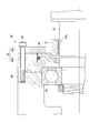
- FIG. 2 is an enlarged detail view including the sealing mechanism 40.
- the seal mechanism 40 includes a seal main body 41, a seal main body support tool 42, a bolt 43, and an O-ring 44 (elastic member).
- the seal body 41 is an annular member that surrounds the rotary shaft 24 when viewed from the axial direction, and is disposed on the side of the bearing 26 fixed to the housing 20 as shown in FIG.
- the seal body 41 has a labyrinth groove 41 a at a portion facing the rotating shaft 24, and the labyrinth groove 41 a is arranged to face the circumferential surface of the rotating shaft 24 with a slight gap. .
- the seal body support tool 42 includes an annular base portion 42a that is in contact with the housing 20 and an annular cover portion 42b.
- the base portion 42 a and the cover portion 42 b are arranged concentrically around the axis of the rotary shaft 24, and sandwich the seal body 41 from the axial direction of the rotary shaft 24. Further, the contact surface between the base portion 42a and the seal body 41 and the contact surface between the cover portion 42b and the seal body 41 are sliding surfaces, and are in the radial direction of the rotary shaft 24 with respect to the seal body 41.
- the seal body 41 is movable in the radial direction of the rotary shaft 24 when a large external force is applied.
- the bolt 43 is inserted through the base portion 42 a and the cover portion 42 b, and fastens these (that is, the seal body support tool 42) to the housing 20.
- the O-ring 44 is sandwiched between the seal body 41 and the seal body support 42 from the radial direction of the rotary shaft 24. That is, the O-ring 44 is interposed between the seal body 41 and the seal body support tool 42.
- the O-ring 44 surrounds the entire circumference of the seal body 41 when viewed from the axial direction of the rotary shaft 24, and ensures airtightness in the entire gap between the seal body 41 and the seal body support tool 42.
- the O-ring 44 is an elastic member made of a resin that can be deformed when the turbo refrigerator 1 is assembled or when an external force is applied to the seal body 41 in the radial direction of the rotary shaft 24.
- the seal body 41 surrounding the rotation shaft 24 is supported by the seal body support tool 42 so as to be movable in the radial direction of the rotation shaft 24, and further, the seal body 41 and the seal body support are supported.
- An O-ring 44 which is an elastic member, is interposed between the tools 42. Since such an O-ring 44 can be flexibly deformed, the position of the seal body 41 with respect to the rotation shaft 24 can be easily adjusted. Therefore, the seal body 41 can be accurately centered with respect to the rotation shaft 24 by the O-ring 44, and the gap between the seal body 41 and the rotation shaft 24 can be made narrower than before.
- the turbo refrigerator 1 of the present embodiment even if the rotating shaft 24 contacts the seal body 41 by the O-ring 44, the impact due to the contact can be absorbed. Therefore, the gap between the seal body 41 and the rotary shaft 24 can be made narrower than before. Therefore, according to the turbo refrigerator 1 of this embodiment, the sealing performance in the sealing mechanism 40 can be improved.
- the labyrinth groove 41a is provided in the part facing the rotating shaft 24 of the seal body 41. For this reason, compared with the case where the labyrinth groove 41a is not provided in the portion of the seal body 41 facing the rotation shaft 24, the shape of the gap between the seal body 41 and the rotation shaft 24 becomes complicated, and the seal body 41 is more sealed. The performance can be improved.
- the O-ring 44 surrounds the entire circumference of the seal body 41 when viewed from the axial direction of the rotary shaft 24. For this reason, it is possible to prevent gas from leaking from the gap between the seal body 41 and the seal body support tool 42.
- the seal mechanism of the present invention is applied to a turbo refrigerator.
- the present invention is not limited to this, and the sealing mechanism of the present invention can be applied to all devices that need to seal around the rotating shaft.
- channel 41a was provided in the opposing part with the rotating shaft 24 of the seal body 41 was employ
- the present invention is not limited to this, and it is also possible to adopt a configuration in which the labyrinth groove 41a is not provided in the portion of the seal body 41 facing the rotation shaft 24.
Landscapes
- Engineering & Computer Science (AREA)
- General Engineering & Computer Science (AREA)
- Mechanical Engineering (AREA)
- Physics & Mathematics (AREA)
- Thermal Sciences (AREA)
- Structures Of Non-Positive Displacement Pumps (AREA)
- Mechanical Sealing (AREA)
- Sealing Using Fluids, Sealing Without Contact, And Removal Of Oil (AREA)
Abstract
Description
本願は、2013年6月4日に日本国に出願された特願2013-117738号に基づき優先権を主張し、その内容をここに援用する。
そこで、例えば特許文献1に示すように、筐体に対して固定され、回転軸の周面に対して僅かな隙間を開けて配置される非接触式のラビリンスシール機構を用いることによって、回転軸に沿って気体が漏出することを防止することが一般的である。
また、特許文献2では、回転軸に対してラビリンスシールを回転軸の半径方向に移動させることによって、回転軸の定常運転時には回転軸とラビリンスシールとの隙間を僅かとし、回転軸の起動停止時には上記隙間を広くして回転軸とラビリンスシールとの接触を防止する機構が開示されている。
さらに、特許文献3では、回転軸に対してラビリンスシールを回転軸の軸方向に移動させることによって、回転軸の定常運転時には回転軸とラビリンスシールとの隙間を僅かとし、回転軸の起動時には上記隙間を広くして回転軸とラビリンスシールとの接触を防止する機構が開示されている。
蒸発器4は、冷水が流通する伝熱管4aを備え、冷媒液X2と冷水との熱交換によって、冷水を冷却すると共に冷媒液X2を蒸発させる。冷媒液X2は、冷水との間の熱交換によって熱を奪って蒸発し、冷媒ガスX4となる。蒸発器4の頂部は、流路R5を介してターボ圧縮機5のガス吸入管5cと接続されている。ターボ圧縮機5には、蒸発器4において蒸発した冷媒ガスX4が流路R5を通って供給される。
Claims (6)
- ターボ圧縮機の筐体に締結され、前記筐体が含む回転軸を囲むシール本体支持具と、
前記シール本体支持具と前記回転軸との間に設けられ、前記シール本体支持具との摺動面において挟持されて前記回転軸を囲むシール本体と、
前記シール本体と前記シール本体支持具によって挟持され、前記シール本体を囲む弾性部材と、
を備えるシール機構。 - 前記シール本体の前記回転軸との対向部にはラビリンス溝が設けられている請求項1記載のシール機構。
- 前記弾性部材は、前記回転軸の軸方向から見て前記シール本体の全周を囲うOリングである請求項1記載のシール機構。
- 前記シール本体支持具は、前記筐体に対して当接される環状のベース部及びカバー部からなり、前記シール本体は前記ベース部と前記カバー部によって挟持されている請求項1に記載のシール機構。
- インペラとモータとを繋ぐ回転軸を有すると共に冷媒の圧縮を行うターボ圧縮機と、前記ターボ圧縮機で圧縮された冷媒を凝縮する凝縮器と、凝縮された冷媒を蒸発させる蒸発器とを備えるターボ冷凍機であって、
前記ターボ圧縮機の回転軸周りのシールを行うシール機構として請求項1に記載のシール機構を備えるターボ冷凍機。 - ターボ圧縮機の筐体に締結され、前記筐体が含む回転軸を軸方向から見て囲む環状のシール本体と、
前記シール本体を前記回転軸の半径方向に移動可能に支持するシール本体支持具と、
前記シール本体と前記シール本体支持具との間に介装される弾性部材と、
を備えるシール機構。
Priority Applications (3)
| Application Number | Priority Date | Filing Date | Title |
|---|---|---|---|
| CN201480031569.2A CN105452738A (zh) | 2013-06-04 | 2014-05-30 | 密封机构及涡轮冷冻机 |
| JP2015521424A JPWO2014196465A1 (ja) | 2013-06-04 | 2014-05-30 | シール機構及びターボ冷凍機 |
| US14/895,608 US10132325B2 (en) | 2013-06-04 | 2014-05-30 | Sealing mechanism and turbo refrigerator |
Applications Claiming Priority (2)
| Application Number | Priority Date | Filing Date | Title |
|---|---|---|---|
| JP2013-117738 | 2013-06-04 | ||
| JP2013117738 | 2013-06-04 |
Publications (1)
| Publication Number | Publication Date |
|---|---|
| WO2014196465A1 true WO2014196465A1 (ja) | 2014-12-11 |
Family
ID=52008110
Family Applications (1)
| Application Number | Title | Priority Date | Filing Date |
|---|---|---|---|
| PCT/JP2014/064416 Ceased WO2014196465A1 (ja) | 2013-06-04 | 2014-05-30 | シール機構及びターボ冷凍機 |
Country Status (5)
| Country | Link |
|---|---|
| US (1) | US10132325B2 (ja) |
| JP (1) | JPWO2014196465A1 (ja) |
| CN (1) | CN105452738A (ja) |
| MY (1) | MY177983A (ja) |
| WO (1) | WO2014196465A1 (ja) |
Cited By (2)
| Publication number | Priority date | Publication date | Assignee | Title |
|---|---|---|---|---|
| CN110552916A (zh) * | 2019-09-22 | 2019-12-10 | 中国航发沈阳发动机研究所 | 一种减振阻尼结构 |
| KR20230017955A (ko) * | 2021-07-28 | 2023-02-07 | 주식회사 모트롤 | 씨일 커버 및 이를 포함하는 구동장치 |
Families Citing this family (4)
| Publication number | Priority date | Publication date | Assignee | Title |
|---|---|---|---|---|
| CN107461556B (zh) | 2016-06-03 | 2024-05-03 | 开利公司 | 法兰连接组件及其装卸方法、管路连接装置及冷却器机组 |
| JP6631475B2 (ja) | 2016-11-15 | 2020-01-15 | 株式会社デンソー | 回転式アクチュエータ |
| WO2018165455A1 (en) | 2017-03-09 | 2018-09-13 | Johnson Controls Technology Company | Back to back bearing sealing systems |
| FR3071281B1 (fr) * | 2017-09-18 | 2022-01-07 | Thermodyn | Machine tournante comprenant un systeme d'amortissement d'un joint d'etancheite |
Citations (3)
| Publication number | Priority date | Publication date | Assignee | Title |
|---|---|---|---|---|
| JPS62119570U (ja) * | 1986-01-21 | 1987-07-29 | ||
| JPH0835499A (ja) * | 1994-07-26 | 1996-02-06 | Kobe Steel Ltd | 回転機械の軸封装置 |
| JP2009186028A (ja) * | 2008-02-01 | 2009-08-20 | Daikin Ind Ltd | ターボ冷凍機 |
Family Cites Families (13)
| Publication number | Priority date | Publication date | Assignee | Title |
|---|---|---|---|---|
| US4900165A (en) * | 1988-08-15 | 1990-02-13 | Union Carbide Corporation | Bearing support system |
| JPH08338537A (ja) * | 1995-06-09 | 1996-12-24 | Toshiba Corp | ラビリンスシール |
| JPH10110831A (ja) * | 1996-10-08 | 1998-04-28 | Mitsubishi Heavy Ind Ltd | 冷凍圧縮機用軸封装置 |
| US6293555B1 (en) * | 2000-02-01 | 2001-09-25 | Josef Sedy | Secondary seal for non-contacting face seals |
| WO2004027218A1 (en) * | 2002-09-18 | 2004-04-01 | Honeywell International Inc. | Turbocharger having variable nozzle device |
| JP2004245187A (ja) | 2003-02-17 | 2004-09-02 | Toshiba Corp | ターボ機械の非接触シール装置およびこれを用いた蒸気タービン設備 |
| US20100061851A1 (en) * | 2005-06-30 | 2010-03-11 | Mann+Hummel Gmbh | Secondary Air Charger |
| JP5167845B2 (ja) * | 2008-02-06 | 2013-03-21 | 株式会社Ihi | ターボ圧縮機及び冷凍機 |
| DE102009012038B4 (de) * | 2009-03-10 | 2014-10-30 | Siemens Aktiengesellschaft | Wellendichtung für eine Strömungsmaschine |
| JP5299150B2 (ja) * | 2009-07-30 | 2013-09-25 | 株式会社日立プラントテクノロジー | 遠心圧縮機 |
| WO2011024928A1 (ja) * | 2009-08-24 | 2011-03-03 | Kawanishi Eiji | 圧力負荷装置を有する天秤使用の重力発電装置と連結するハイブリッド発電装置。 |
| DE102010026336A1 (de) * | 2010-07-07 | 2012-01-12 | Siemens Aktiengesellschaft | Wellendichtungsvorrichtung |
| JP5599368B2 (ja) * | 2011-06-08 | 2014-10-01 | 三菱電機株式会社 | 電動ターボチャージャのモータロータ構造とその組付け方法 |
-
2014
- 2014-05-30 MY MYPI2015704414A patent/MY177983A/en unknown
- 2014-05-30 US US14/895,608 patent/US10132325B2/en active Active
- 2014-05-30 JP JP2015521424A patent/JPWO2014196465A1/ja active Pending
- 2014-05-30 WO PCT/JP2014/064416 patent/WO2014196465A1/ja not_active Ceased
- 2014-05-30 CN CN201480031569.2A patent/CN105452738A/zh active Pending
Patent Citations (3)
| Publication number | Priority date | Publication date | Assignee | Title |
|---|---|---|---|---|
| JPS62119570U (ja) * | 1986-01-21 | 1987-07-29 | ||
| JPH0835499A (ja) * | 1994-07-26 | 1996-02-06 | Kobe Steel Ltd | 回転機械の軸封装置 |
| JP2009186028A (ja) * | 2008-02-01 | 2009-08-20 | Daikin Ind Ltd | ターボ冷凍機 |
Cited By (3)
| Publication number | Priority date | Publication date | Assignee | Title |
|---|---|---|---|---|
| CN110552916A (zh) * | 2019-09-22 | 2019-12-10 | 中国航发沈阳发动机研究所 | 一种减振阻尼结构 |
| KR20230017955A (ko) * | 2021-07-28 | 2023-02-07 | 주식회사 모트롤 | 씨일 커버 및 이를 포함하는 구동장치 |
| KR102592519B1 (ko) | 2021-07-28 | 2023-10-24 | 주식회사 모트롤 | 씨일 커버 및 이를 포함하는 구동장치 |
Also Published As
| Publication number | Publication date |
|---|---|
| MY177983A (en) | 2020-09-28 |
| US20160131150A1 (en) | 2016-05-12 |
| JPWO2014196465A1 (ja) | 2017-02-23 |
| US10132325B2 (en) | 2018-11-20 |
| CN105452738A (zh) | 2016-03-30 |
Similar Documents
| Publication | Publication Date | Title |
|---|---|---|
| WO2014196465A1 (ja) | シール機構及びターボ冷凍機 | |
| JP6056270B2 (ja) | ターボ圧縮機及びターボ冷凍機 | |
| US8245529B2 (en) | Turbo compressor and refrigerator | |
| JP6111915B2 (ja) | ターボ圧縮機及びターボ冷凍機 | |
| WO2019188616A1 (ja) | ターボ圧縮機およびこれを備えたターボ冷凍機 | |
| JP2015113817A (ja) | スクロール型圧縮機 | |
| KR102113036B1 (ko) | 터보 압축기 및 이를 포함하는 터보 냉동기 | |
| JP6004004B2 (ja) | ターボ冷凍機 | |
| JP5272941B2 (ja) | ターボ圧縮機及び冷凍機 | |
| US20240263638A1 (en) | Shaft seal structure, compressor, and refrigeration apparatus | |
| JP2020159294A (ja) | ターボ圧縮機及び冷凍サイクル装置 | |
| JP6123889B2 (ja) | ターボ冷凍機 | |
| WO2020129326A1 (ja) | ターボ圧縮機及び冷凍サイクル装置 | |
| JP7490367B2 (ja) | 冷凍サイクル装置 | |
| JP5994744B2 (ja) | 軸封装置の調整方法 |
Legal Events
| Date | Code | Title | Description |
|---|---|---|---|
| WWE | Wipo information: entry into national phase |
Ref document number: 201480031569.2 Country of ref document: CN |
|
| 121 | Ep: the epo has been informed by wipo that ep was designated in this application |
Ref document number: 14807826 Country of ref document: EP Kind code of ref document: A1 |
|
| ENP | Entry into the national phase |
Ref document number: 2015521424 Country of ref document: JP Kind code of ref document: A |
|
| WWE | Wipo information: entry into national phase |
Ref document number: 14895608 Country of ref document: US |
|
| NENP | Non-entry into the national phase |
Ref country code: DE |
|
| 122 | Ep: pct application non-entry in european phase |
Ref document number: 14807826 Country of ref document: EP Kind code of ref document: A1 |