WO2014196389A1 - オート・フォーカス装置およびその動作制御方法 - Google Patents
オート・フォーカス装置およびその動作制御方法 Download PDFInfo
- Publication number
- WO2014196389A1 WO2014196389A1 PCT/JP2014/063775 JP2014063775W WO2014196389A1 WO 2014196389 A1 WO2014196389 A1 WO 2014196389A1 JP 2014063775 W JP2014063775 W JP 2014063775W WO 2014196389 A1 WO2014196389 A1 WO 2014196389A1
- Authority
- WO
- WIPO (PCT)
- Prior art keywords
- focus
- evaluation value
- phase difference
- difference
- unit
- Prior art date
- Legal status (The legal status is an assumption and is not a legal conclusion. Google has not performed a legal analysis and makes no representation as to the accuracy of the status listed.)
- Ceased
Links
Images




Classifications
-
- G—PHYSICS
- G03—PHOTOGRAPHY; CINEMATOGRAPHY; ANALOGOUS TECHNIQUES USING WAVES OTHER THAN OPTICAL WAVES; ELECTROGRAPHY; HOLOGRAPHY
- G03B—APPARATUS OR ARRANGEMENTS FOR TAKING PHOTOGRAPHS OR FOR PROJECTING OR VIEWING THEM; APPARATUS OR ARRANGEMENTS EMPLOYING ANALOGOUS TECHNIQUES USING WAVES OTHER THAN OPTICAL WAVES; ACCESSORIES THEREFOR
- G03B13/00—Viewfinders; Focusing aids for cameras; Means for focusing for cameras; Autofocus systems for cameras
- G03B13/32—Means for focusing
- G03B13/34—Power focusing
- G03B13/36—Autofocus systems
-
- H—ELECTRICITY
- H04—ELECTRIC COMMUNICATION TECHNIQUE
- H04N—PICTORIAL COMMUNICATION, e.g. TELEVISION
- H04N23/00—Cameras or camera modules comprising electronic image sensors; Control thereof
- H04N23/60—Control of cameras or camera modules
- H04N23/67—Focus control based on electronic image sensor signals
- H04N23/672—Focus control based on electronic image sensor signals based on the phase difference signals
-
- G—PHYSICS
- G02—OPTICS
- G02B—OPTICAL ELEMENTS, SYSTEMS OR APPARATUS
- G02B7/00—Mountings, adjusting means, or light-tight connections, for optical elements
- G02B7/02—Mountings, adjusting means, or light-tight connections, for optical elements for lenses
- G02B7/04—Mountings, adjusting means, or light-tight connections, for optical elements for lenses with mechanism for focusing or varying magnification
- G02B7/09—Mountings, adjusting means, or light-tight connections, for optical elements for lenses with mechanism for focusing or varying magnification adapted for automatic focusing or varying magnification
-
- G—PHYSICS
- G02—OPTICS
- G02B—OPTICAL ELEMENTS, SYSTEMS OR APPARATUS
- G02B7/00—Mountings, adjusting means, or light-tight connections, for optical elements
- G02B7/28—Systems for automatic generation of focusing signals
- G02B7/282—Autofocusing of zoom lenses
-
- G—PHYSICS
- G02—OPTICS
- G02B—OPTICAL ELEMENTS, SYSTEMS OR APPARATUS
- G02B7/00—Mountings, adjusting means, or light-tight connections, for optical elements
- G02B7/28—Systems for automatic generation of focusing signals
- G02B7/34—Systems for automatic generation of focusing signals using different areas in a pupil plane
- G02B7/343—Systems for automatic generation of focusing signals using different areas in a pupil plane using light beam separating prisms
-
- H—ELECTRICITY
- H04—ELECTRIC COMMUNICATION TECHNIQUE
- H04N—PICTORIAL COMMUNICATION, e.g. TELEVISION
- H04N23/00—Cameras or camera modules comprising electronic image sensors; Control thereof
- H04N23/50—Constructional details
- H04N23/55—Optical parts specially adapted for electronic image sensors; Mounting thereof
-
- H—ELECTRICITY
- H04—ELECTRIC COMMUNICATION TECHNIQUE
- H04N—PICTORIAL COMMUNICATION, e.g. TELEVISION
- H04N23/00—Cameras or camera modules comprising electronic image sensors; Control thereof
- H04N23/60—Control of cameras or camera modules
- H04N23/61—Control of cameras or camera modules based on recognised objects
-
- H—ELECTRICITY
- H04—ELECTRIC COMMUNICATION TECHNIQUE
- H04N—PICTORIAL COMMUNICATION, e.g. TELEVISION
- H04N23/00—Cameras or camera modules comprising electronic image sensors; Control thereof
- H04N23/60—Control of cameras or camera modules
- H04N23/61—Control of cameras or camera modules based on recognised objects
- H04N23/611—Control of cameras or camera modules based on recognised objects where the recognised objects include parts of the human body
-
- H—ELECTRICITY
- H04—ELECTRIC COMMUNICATION TECHNIQUE
- H04N—PICTORIAL COMMUNICATION, e.g. TELEVISION
- H04N23/00—Cameras or camera modules comprising electronic image sensors; Control thereof
- H04N23/60—Control of cameras or camera modules
- H04N23/62—Control of parameters via user interfaces
-
- H—ELECTRICITY
- H04—ELECTRIC COMMUNICATION TECHNIQUE
- H04N—PICTORIAL COMMUNICATION, e.g. TELEVISION
- H04N23/00—Cameras or camera modules comprising electronic image sensors; Control thereof
- H04N23/60—Control of cameras or camera modules
- H04N23/63—Control of cameras or camera modules by using electronic viewfinders
- H04N23/631—Graphical user interfaces [GUI] specially adapted for controlling image capture or setting capture parameters
- H04N23/632—Graphical user interfaces [GUI] specially adapted for controlling image capture or setting capture parameters for displaying or modifying preview images prior to image capturing, e.g. variety of image resolutions or capturing parameters
-
- H—ELECTRICITY
- H04—ELECTRIC COMMUNICATION TECHNIQUE
- H04N—PICTORIAL COMMUNICATION, e.g. TELEVISION
- H04N23/00—Cameras or camera modules comprising electronic image sensors; Control thereof
- H04N23/60—Control of cameras or camera modules
- H04N23/63—Control of cameras or camera modules by using electronic viewfinders
- H04N23/633—Control of cameras or camera modules by using electronic viewfinders for displaying additional information relating to control or operation of the camera
- H04N23/635—Region indicators; Field of view indicators
-
- H—ELECTRICITY
- H04—ELECTRIC COMMUNICATION TECHNIQUE
- H04N—PICTORIAL COMMUNICATION, e.g. TELEVISION
- H04N23/00—Cameras or camera modules comprising electronic image sensors; Control thereof
- H04N23/60—Control of cameras or camera modules
- H04N23/667—Camera operation mode switching, e.g. between still and video, sport and normal or high- and low-resolution modes
-
- G—PHYSICS
- G02—OPTICS
- G02B—OPTICAL ELEMENTS, SYSTEMS OR APPARATUS
- G02B7/00—Mountings, adjusting means, or light-tight connections, for optical elements
- G02B7/28—Systems for automatic generation of focusing signals
- G02B7/36—Systems for automatic generation of focusing signals using image sharpness techniques, e.g. image processing techniques for generating autofocus signals
-
- G—PHYSICS
- G02—OPTICS
- G02B—OPTICAL ELEMENTS, SYSTEMS OR APPARATUS
- G02B7/00—Mountings, adjusting means, or light-tight connections, for optical elements
- G02B7/28—Systems for automatic generation of focusing signals
- G02B7/36—Systems for automatic generation of focusing signals using image sharpness techniques, e.g. image processing techniques for generating autofocus signals
- G02B7/38—Systems for automatic generation of focusing signals using image sharpness techniques, e.g. image processing techniques for generating autofocus signals measured at different points on the optical axis, e.g. focussing on two or more planes and comparing image data
Definitions
- the present invention relates to an auto-focus device and an operation control method thereof.
- the camera auto focus includes phase difference AF (auto focus), contrast AF, and the like.
- phase difference AF light entering from a lens is divided into two or more by pupil division and guided to a sensor for phase difference AF, and the position deviation direction and the amount of position deviation in the division direction of each of the pupil divided images are determined. Based on this, the in-focus direction and the amount of focus shift are determined.
- Contrast AF searches for a place where the contrast is high while moving the focus lens based on the image captured on the image sensor, and focuses.
- a contrast AF optical path length difference AF
- a contrast AF optical path length difference AF
- Contrast AF has a high focus accuracy but low focus speed
- phase difference AF has high focus speed but low focus accuracy.
- both contrast AF and phase difference AF are mounted.
- the focus lens is moved by a minute distance to adjust the focus direction. If the width of the WOB is searched (Patent Document 1), or the detection area of the phase difference AF and the detection area of the contrast AF coincide with each other and the focus evaluation value of the contrast AF exceeds the threshold, the contrast There is also one using an AF focus evaluation value (Patent Document 2).
- the phase difference AF In the phase difference AF, the place where the image is formed on the imaging surface of the phase difference image sensor changes depending on the distance to the subject. Therefore, the range to be focused cannot be set arbitrarily, but the contrast AF is the range to be focused arbitrarily. Can be set.
- the focus lens In the phase difference AF, the focus lens is moved so that the center part of the imaging range is in focus. Therefore, after controlling the focus using the phase difference AF, if an arbitrary range is controlled using the contrast AF, The area of the image that is in focus at the time of switching is also switched, and the target subject is not smoothly focused and a sense of incongruity occurs. None of the cited references 1 and 2 considers such a sense of incongruity.
- An object of the present invention is to eliminate a sense of discomfort when switching from phase difference AF to contrast AF when an arbitrary range is set as a focusing target range.
- An auto-focus device includes a focus target range setting unit that sets a focus target range to be focused in an imaging range, and a plurality of light beams that are incident through a focus lens and are divided into a plurality by pupil division.
- a phase difference AF unit for outputting a first focus evaluation value signal indicating a focus shift amount based on an output signal obtained from one phase difference image pickup device on which an object image is formed on an image pickup surface; a focus lens; Second focus evaluation indicating the amount of focus shift based on the respective output signals of the first image sensor and the second image sensor that are arranged at different positions in the optical path of the light incident therethrough
- An optical path length difference AF unit that outputs a value signal, a focus position estimation unit that estimates a focus position based on at least one of the first focus evaluation value signal and the second focus evaluation value signal, Len A focus / lens position detection unit for detecting the position of the lens, a focus / lens position evaluation unit for calculating a difference between the focus / lens position and the in-
- the focus evaluation value signal is a focus evaluation value signal and the difference is greater than the second threshold value and less than or equal to the first threshold value, it is based on the output signal obtained from the focus target range of the phase difference image sensor.
- the first focus evaluation value signal output from the phase difference AF unit is used as the focus evaluation value signal and the difference is equal to or smaller than the second threshold value, the first image sensor and the second image sensor Output signal obtained from the focus range
- An AF switching unit that uses the second focus evaluation value signal output to the optical path length difference AF unit as a focus evaluation value signal based on the focus evaluation value signal output from the AF switching unit.
- a focus / lens movement control unit for moving the lens is provided.
- the present invention also provides an operation control method suitable for an autofocus device. That is, the focusing target range setting unit sets a focusing target range to be focused in the imaging range, and the phase difference AF unit is configured to divide the light incident through the focus lens into a plurality of parts by pupil division.
- a first focus evaluation value signal indicating a focus shift amount is output based on an output signal obtained from one phase difference imaging element on which the subject image is formed on the imaging surface, and the optical path length difference AF unit includes: A second that indicates the amount of focus shift based on the output signals of the first image sensor and the second image sensor that are disposed at different positions in the optical path of the light incident through the focus lens.
- the focus evaluation value signal is output, and the focus position estimation unit estimates the focus position based on at least one of the first focus evaluation value signal and the second focus evaluation value signal, and the focus. ⁇
- the lens position detector The lens position is detected, the focus lens position evaluation unit calculates the difference between the focus lens position and the in-focus position estimated by the in-focus position estimation unit, and the AF switching unit When the difference between the position and the estimated in-focus position is larger than the first threshold value, the first output from the phase difference AF unit based on the output signal obtained from the center portion of the phase difference image sensor.
- the difference is greater than the second threshold and less than or equal to the first threshold, the output obtained from the focus target range of the phase difference image sensor If the first focus evaluation value signal output from the phase difference AF unit based on the signal is a focus evaluation value signal, and the difference is less than or equal to the second threshold value, the first image sensor and the second image sensor Output signal obtained from the focus target range of the image sensor And the second focus evaluation value signal output to the optical path length difference AF unit is used as the focus evaluation value signal, and the focus / lens movement control unit converts the focus evaluation value signal output from the AF switching unit into the focus evaluation value signal. Based on this, the focus lens is moved.
- the phase difference AF unit is obtained from one phase difference imaging device in which a plurality of subject images obtained by dividing light incident through the focus lens into a plurality of parts by pupil division are formed on the imaging surface.
- a first focus evaluation value signal indicating a focus shift amount is output based on the output signal.
- the optical path length difference AF unit outputs the output signals of the first image sensor and the second image sensor, which are arranged at positions where the optical path lengths are different from each other, in the optical path of the light incident through the focus lens. Based on this, a second focus evaluation value signal indicating the amount of focus deviation is output.
- a focus position is estimated based on at least one of the first focus evaluation value signal and the second focus evaluation value signal, and the difference between the estimated focus position and the position of the focus lens Is calculated.
- the focus evaluation value for moving the focus lens by the first focus evaluation value signal based on the output signal obtained from the center portion of the phase difference image sensor. Value signal. If the calculated difference is greater than the second threshold value (the second threshold value is less than the first threshold value) and less than or equal to the first threshold value, the object to be focused on by the phase difference image sensor
- the first focus evaluation value signal based on the output signal obtained from the range is used as the focus evaluation value signal for moving the focus lens.
- the second based on the output signal obtained from the focusing target range of the first image sensor and the second image sensor constituting the optical path length difference AF unit.
- the focus evaluation value signal is used as a focus evaluation value signal for moving the focus lens. Since the focus evaluation value signal for moving the focus lens is changed in accordance with the calculated magnitude of the difference, it is possible to prevent the area of the focused image from changing suddenly and to target the target subject. It becomes possible to focus smoothly.
- the AF switching unit has a difference calculated by the focus / lens position evaluation unit equal to or greater than a third threshold value equal to or greater than a first threshold value and a second threshold value. If it is between the fourth threshold value and the threshold value, the larger the difference, the closer to the center portion, and the smaller the difference, the closer to the in-focus range. It is preferable that the first focus evaluation value signal output from the phase difference AF unit based on the output signal obtained from the extraction portion of the phase difference image sensor is used as the focus evaluation value signal.
- the focus position estimation unit outputs, for example, the first estimation after the focus target range is set by the focus target range setting unit from the phase difference AF unit based on the output signal obtained from the center portion of the phase difference image sensor.
- the first focus evaluation value signal thus obtained is used as a focus evaluation value signal.
- the phase difference image sensor is, for example, an area sensor. Moreover, it is preferable that the focus target range, the central portion, and the extraction portion have the same size.
- the structure of an imaging lens unit is shown.
- the relationship between the image sensor for optical path length difference AF and the imaging position of a subject image is shown.
- the relationship between the AF evaluation value and the focus / lens position is shown.
- the positional relationship of the subject is shown.
- the positional relationship of the subject is shown.
- the subject positional relationship is shown.
- phase difference AF evaluation value The relationship between the phase difference AF evaluation value and the focus / lens position is shown.
- the relationship between the differential AF evaluation value and the focus / lens position is shown. It is a flowchart which shows a focusing process procedure.
- the relationship between the imaging range and the central area or the focusing target range is shown. It is a flowchart which shows a focusing process procedure. It is a flowchart which shows a focusing process procedure.
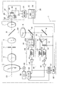
- FIG. 1 shows an embodiment of the present invention, and shows an optical configuration of a part of a photographing lens unit 1 and a camera body 20 used for broadcasting or the like.
- the taking lens unit 1 is detachably attached to the camera body 20.
- the photographic lens unit 1 includes a focus lens (focus lens group) 2, a zoom lens (zoom lens group) 3, and a front relay so as to have an optical axis common to the optical axis O1 of the photographic lens unit 1
- a lens (front relay / lens group) 5 and a rear relay / lens (rear relay / lens group) 7 are included.
- a diaphragm 4 is arranged between the zoom lens 3 and the front relay lens 5 so that the optical axis O1 of the photographing lens unit 1 passes through the center.
- a half mirror 6 is arranged between the front relay lens 5 and the rear relay lens 7.
- the camera body 20 is provided with a color separation prism 21 having an optical axis common to the optical axis O1 of the photographing lens unit 1 when the photographing lens unit 1 is mounted.
- the color separation prism 21 includes a first prism 22, a second prism 23, and a third prism 24, and incident light is separated into a red component, a green component, and a blue component.
- An imaging CCD 26 and a third imaging CCD 27 are arranged.
- the photographing lens unit 1 includes an AF relay lens (AF relay lens) that uses a part of the light reflected at the center of the half mirror 6 as an optical axis [optical axis for AF (auto focus)] O2.
- Lens group 8 is provided.
- a half mirror 40 (which may be a reflecting prism) is provided downstream of the AF relay lens 8.
- a total reflection mirror 9 is provided after the half mirror 40.
- An optical path length difference AF sensor 55 is provided in the total reflection direction of the total reflection mirror 9.
- the optical path length difference AF sensor 55 includes a split prism 10 composed of a first prism 11 and a second prism 12.
- a first AF CCD 13 and a second AF CCD 14 are provided on the exit surface of the first prism 11 and the exit surface of the second prism 12, respectively.
- the light beam incident on the photographic lens unit 1 passes through the focus lens 2, zoom lens 3, aperture 4, front relay lens 5, half mirror 6 and rear relay lens 7, and enters the camera body 20. Led.
- the light beam is decomposed into a red light component, a green light component, and a blue light component, respectively, and the first image pickup CCD 25, the second image pickup CCD 26, and the third image pickup device.
- a subject image is formed on each of the CCDs 27 for use.
- Video signals representing subject images of the red light component, the green light component, and the blue light component are output from the first imaging CCD 25, the second imaging CCD 26, and the third imaging CCD 27, respectively.
- Video signals representing subject images of the red light component, the green light component, and the blue light component output from the first image pickup CCD 25, the second image pickup CCD 26, and the third image pickup CCD 27 are displayed on the display control device 31. Given to. When the display device 32 is controlled by the display control device 31, a subject image obtained by imaging is displayed on the display screen of the display device 32. The photographer determines the camera angle while viewing the subject image displayed on the display screen of the display device 32.
- a touch panel 33 is also formed on the display screen of the display device 32.
- a signal indicating the area is input to the control device 60 of the imaging lens unit 1.
- the focus lens 2 is controlled so that the subject image in the desired area touched by the cameraman is in focus.
- the focus lens 2 may be controlled such that a face detected by face detection or the like is not designated by the cameraman and is focused.
- the light beam incident on the taking lens unit 1 is partially reflected by the half mirror 6.
- the light beam reflected by the half mirror 6 passes through the AF relay lens 8 and is guided to the half mirror 40.
- phase difference AF unit Part of the light incident on the half mirror 40 is reflected and incident on the phase difference sensor 41 included in the phase difference AF sensor 46 (phase difference AF unit).
- the phase difference sensor 41 includes two separator lenses 42A and 42B. These separator lenses 42A and 43A divide the subject image into two by pupil division. Two subject images are formed on the light receiving surface of one phase difference imaging device 43 (for example, an area sensor). An output signal from the phase difference image sensor 43 is input to the evaluation value calculation circuit 44. In the evaluation value calculation circuit 44, a phase difference AF evaluation value representing the degree of focusing of the subject image obtained by imaging is generated from the interval between the two subject images. A signal representing the phase difference AF evaluation value (first focus evaluation value signal indicating the amount of focus shift) is input to the selector 63 via the amplifier circuit 45.
- the light transmitted through the half mirror 40 is totally reflected by the total reflection mirror 9.
- the light beam totally reflected by the total reflection mirror 9 enters the splitting prism 10, a part thereof enters the first optical path length difference CCD 13 (first image pickup device), and the rest enters the second optical path length difference AF.
- CCD 14 second image sensor
- An AF signal is output from each of the first optical path length difference AF CCD 13 and the second optical path length difference AF CCD 14.
- the first optical path length difference AF CCD 13 and the second optical path length difference AF CCD 14 are arranged at positions where the optical path lengths are different from each other in the optical path incident through the focus lens.
- Signals output from the first optical path length difference AF CCD 13 and the second optical path length difference AF CCD 14 are input to the evaluation value calculation circuits 51 and 52, respectively, and indicate the degree of focusing of the focus lens 2. Is evaluated. Signals representing the evaluation values calculated in the evaluation value calculation circuits 51 and 52 are supplied to the subtraction circuit 53. The signal representing the evaluation value calculated in the evaluation value calculating circuit 52 is subtracted in the subtracting circuit 53 from the signal representing the evaluation value calculated in the evaluation value calculating circuit 51 to obtain a differential AF evaluation value. A signal representing the differential AF evaluation value (second focus evaluation value signal indicating the amount of focus deviation) is amplified in the amplifier circuit 54 and applied to the selector 63 (AF switching unit).
- the phase difference AF evaluation value signal output from the amplification circuit 45 and the difference AF evaluation value signal output from the amplification circuit 54 are also input to the switching control circuit 61.
- the selector 63 is controlled by the switching control circuit 61 (AF switching unit) based on the input phase difference AF evaluation value signal and the difference AF evaluation value signal, and the phase difference AF evaluation value signal output from the amplification circuit 45 or the amplification circuit 54. Any one of the differential AF evaluation value signals output from is supplied to the gain control amplification circuit 64.
- the input signal is amplified using a gain coefficient set in accordance with the phase difference AF evaluation value signal and the difference AF evaluation value signal, and is supplied to the focus motor 65 as a control signal representing the rotation direction and the rotation speed. It is done.
- the focus lens 2 is moved by the focus motor 65 (focus / lens movement control unit).
- the phase difference AF evaluation value signal output from the amplifying circuit 45 and the differential AF evaluation value signal output from the amplifying circuit 54 simply pass through the switching control circuit 61 to control the above-described circuits and the like. Also enter 60.
- the control circuit 60 estimates the in-focus position using at least one of the input phase difference AF evaluation value signal and differential AF evaluation value signal (in-focus position estimation unit).
- the control circuit 60 also calculates the difference between the position of the focus lens 2 and the estimated focus position (focus lens position evaluation unit).
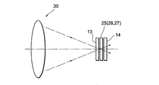
- FIG. 2 shows the relationship between the optical distances of the first imaging CCD 25, the second imaging CCD 26, the third imaging CCD 27, the first optical path length difference AF CCD 13, and the second optical path length difference AF CCD 14. Is shown.
- An optical system for causing light to enter the first imaging CCD 25, the second imaging CCD 26, the third imaging CCD 27, the first optical path length difference AF CCD 13, and the second optical path length difference AF CCD 14 is provided. Represented by lens 30.
- the optical distances until the light enters the first imaging CCD 25, the second imaging CCD 26, and the third imaging CCD 27 are all equal.
- the optical distance until the light enters the first optical path length difference AF CCD 13 is a predetermined distance from the first imaging CCD 25, the second imaging CCD 26, and the third imaging CCD 27.
- the optical distance until the light enters the second optical path length difference AF CCD 14 is equal to a predetermined distance from the first imaging CCD 25, the second imaging CCD 26, and the third imaging CCD 27.
- the first imaging CCD 25, the second imaging CCD 26, the third imaging CCD 27, the first optical path length difference AF CCD 13, and the second optical path length difference so as to be equal when they are arranged after a distance.
- the positional relationship of the AF CCD 14 (optically equidistantly spaced positions) is defined. Temporarily, the first imaging CCD 25, the second imaging CCD 26, the third imaging CCD 27, the first optical path length difference AF CCD 13, and the second optical path length difference AF CCD 14 are arranged on the same optical axis. The first optical path length difference AF CCD 13 and the second optical path length difference AF CCD 14 are arranged at equally spaced positions before and after the first imaging CCD 25, the second imaging CCD 26, and the third imaging CCD 27. It is equivalent to what is done.
- FIG. 3 shows the relationship between the AF evaluation value and the position of the focus lens 2.
- a graph G51 is obtained from the evaluation value signal calculated by the evaluation value calculation circuit 51 based on the signal output from the first optical path length difference AF CCD 13, and the signal output from the second optical path length difference AF CCD 14 is obtained.
- a graph G52 is obtained from the evaluation value signal calculated by the evaluation value calculation circuit 52 based on the above.
- the first imaging CCD 25, the second imaging CCD 26, the third imaging CCD 27, the first optical path length difference AF CCD 13, and the second optical path length difference AF are assumed to be on the same optical axis.
- the first optical path length difference AF CCD 13 and the second optical path length difference are arranged at equal intervals before and after the first imaging CCD 25, the second imaging CCD 26, and the third imaging CCD 27. Since this is equivalent to the arrangement of the AF CCD 14, at the intersections of the graphs G51 and G52 obtained from the signals of the first optical path length difference AF CCD 13 and the second optical path length difference AF CCD 14, respectively.
- a certain focus lens position P0 is the position of the focus lens 2 where the subject image is focused on the first imaging CCD 25, the second imaging CCD 26, and the third imaging CCD 27.
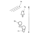
- FIG. 4 is an example of a subject to be imaged.
- male 71, female 72, tree 73, and road 74 are included as imaging targets. Assume that a male 71, a female 72, a tree 73, and a road 74 are arranged in this order from the camera on which the imaging lens unit 1 is mounted.
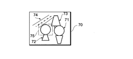
- FIG. 5 shows a subject image 70 obtained by imaging the imaging target shown in FIG.
- the subject image 70 includes a male image 71, a female image 72, a tree image 73, and a road image 74.
- Such a subject image is displayed on the display screen of the display device 32 provided in the camera body 20.
- the photographer touches the touch panel 33 formed on the display screen to specify a desired range of the subject image 70 displayed on the display screen as the focus target range.
- the face image portion of the female image 72 is designated as the focusing target range 75.
- the subject image captured by the first phase difference AF CCD 13 and the second phase difference AF CCD 14 included in the phase difference sensor 55 is the same as the subject image 70 obtained by the camera body 20, it is designated by the cameraman.
- the image in the range corresponding to the in-focus target range 75 corresponds to the image in the in-focus target range 75 specified in the subject image 70. Therefore, a signal obtained based on a range corresponding to the focusing target range 75 among the light receiving surfaces of the first phase difference AF CCD 12 and the second phase difference AF CCD 13 included in the phase difference sensor 55 is used.
- the focus lens 2 is moved, the image within the focusing target range 75 is focused.
- the focus lens 2 is moved on the light receiving surface of the phase difference imaging element 43 included in the phase difference AF sensor 46 using a signal obtained based on a range corresponding to the focusing target range 75.
- the image in the focusing target range 75 may not be in focus.
- FIG. 6 shows that a subject image 70 obtained by imaging a subject is divided into two images (a reference image 80A and a reference image 80B) by separator lenses 42A and 42B included in the phase difference sensor 41.
- An image is formed on the light receiving surface of the image sensor 43.
- Reference image 80A includes male image 71, female image 72, tree image 73 and male image 71A corresponding to road image 74, female image 72A, tree image 73A and road image 74A.
- the reference image 80B also includes a male image 71, a female image 72, a tree image 73 and a male image 71B corresponding to the road image 74, a female image 72B, a tree image 73B, and a road image 74B. It is.
- focus target ranges 75A and 75B designated by the photographer are also displayed.
- FIG. 7 is an example of the reference images 80A and 80B formed on the light receiving surface of the phase difference image sensor 43.
- FIG. 7 The example shown in FIG. 7 is obtained when the focus lens 2 is positioned so that the subject at a distance between the male 71 and the female 72 is in focus in FIG. As shown in FIG. 8, this state is almost equivalent to the fact that the male 71 is closer to the in-focus position and the female 72, the tree 73 and the road 74 are farther from the in-focus position.
- the distance between the standard image 80A and the reference image 80B is a standard distance.
- This reference distance is equal to the distance between focused images among the images included in each of the reference image 80A and the reference image 80B.
- the distance between images of subjects farther than the subject in focus is shorter than the reference distance, and the distance between images of subjects close to the subject in focus is longer than the reference distance. Since the male 71 is closer to the focus position, the distance between the male images 71A and 71B is longer than the reference distance, and the female 72, the tree 73 and the road 74 are farther from the focus position. The distance is shorter than the reference distance.
- the female images 72A and 72B are moved inward, even if the focus target ranges 75A and 75B are defined at positions corresponding to the positions designated by the photographer in the standard image 80A and the reference image 80B.
- the ranges 75A and 75B do not correspond to the faces of the female images 72A and 72B, and the positions of the faces are shifted inside the focus target ranges 75A and 75B. For this reason, even if the focus lens 2 is moved based on the signals obtained from the focusing target ranges 75A and 75B, the image within the range designated by the cameraman does not come into focus.
- FIG. 9 The example shown in FIG. 9 is obtained when the focus lens 2 is positioned so that the woman 72 is in focus in FIG. As shown in FIG. 10, this state is almost equivalent to the fact that the female 72 is at the in-focus position, but the male 71 is closer to the in-focus position, and the tree 73 and the road 74 are further from the in-focus position. .
- the distance between the male images 71A and 71B is longer than the reference distance, and the tree 73 and the road 74 are far from the in-focus position.
- the distance between the images 73A and 73B and the distance between the road images 74A and 74B are both shorter than the reference distance.
- the female 72 is at the in-focus position, the distance between the female images 72A and 72B is substantially equal to the reference distance.
- these ranges 75A and 75B are the faces of the female images 72A and 72B.
- FIG. 11 The example shown in FIG. 11 is obtained in FIG. 4 when the focus lens 2 is positioned so that the subject at a distance between the woman 72 and the tree 73 is in focus. This state is almost equivalent to that the male 71 and the female 72 are closer to the focus position and the tree 73 and the road 74 are farther from the focus position as shown in FIG.
- the distance between the tree images 73A and 73B is shorter than the reference distance.
- the female 72 is closer to the in-focus position, the distance between the female images 72A and 72B is longer than the reference distance.
- the female images 72A and 72B are shifted outward, so that in the base image 80A and the reference image 80B, the focus target range 75A is located at a position corresponding to the position designated by the photographer.
- the ranges 75A and 75B do not correspond to the faces of the female images 72A and 72B, and the face position is shifted to the inside of the focus target ranges 75A and 75B. . For this reason, even if the focus lens 2 is moved based on the signals obtained from the focusing target ranges 75A and 75B, the image within the range designated by the cameraman does not come into focus.
- the focus lens 2 is obtained using a signal obtained from the range corresponding to the focus target range of the phase difference image sensor 43.
- the image within the in-focus target range is focused by moving, but if the subject represented by the image included in the in-focus target range is significantly out of the in-focus position, the in-focus target of the phase difference image sensor 43 Even if the focus lens 2 is moved using a signal obtained from a range corresponding to the range, the image within the focusing target range set by the cameraman is not focused.
- the signal obtained from the phase difference image sensor 43 at the center weight regardless of the set focus target range.
- the focus lens 2 is moved using and the subject represented by the image included in the in-focus target range is almost at the in-focus position, a signal obtained from the range corresponding to the in-focus target range of the phase difference image sensor 43 is obtained. In this way, the focus lens 2 is moved. Thereafter, the focus lens 2 is moved using the optical path length difference AF sensor 55 so that the in-focus target range is in focus.
- FIG. 13 shows the relationship between the phase difference AF evaluation value and the position of the focus lens 2.
- the horizontal axis indicates the position of the focus lens 2, and the vertical axis indicates the phase difference AF evaluation value.
- the position of the focus lens 2 is determined from the relationship between the calculated phase difference AF evaluation value and the graph G0. If the phase difference AF evaluation value is 0, the position P0 of the focus lens 2 is substantially equal to the focus position at which the subject image is focused.
- the relationship between the AF evaluation value of the graph G0 and the focus lens 2 is a graph on a step, and when the phase difference AF evaluation value is 0, the in-focus position P0 may not correspond completely. is there.
- FIG. 14 is a graph G53 showing the relationship between the differential AF evaluation value signal output from the subtraction circuit 53 and the position of the focus lens 2.
- the horizontal axis is the focus lens position, and the vertical axis is the differential AF evaluation value.
- the positional relationship between the differential AF evaluation value and the focus lens 2 corresponds one to one. If the differential AF evaluation value is known, the position of the focus lens 2 between the position P11 of the focus lens 2 corresponding to the positive peak value D11 and the position P12 of the focus lens 2 corresponding to the negative peak value D12. I understand. When the focus lens 2 is between the positions P10 and P11, the focus lens 2 can be positioned at the focus position P0 using the differential AF evaluation value (optical path length difference AF possible range).
- the subject images formed on the first optical path length difference AF CCD 12 and the second optical path length difference AF CCD 13 are the first imaging CCD 25, the second imaging CCD 26, and the third imaging CCD.
- the object image formed on the imaging CCD 27 corresponds to the positional relationship, but the object image formed on the phase difference imaging element 43 has the first optical path length difference AF CCD 12 and the second optical path length. It does not correspond to the subject image formed on the difference AF CCD 13 or the subject image formed on the first imaging CCD 25, the second imaging CCD 26, and the third imaging CCD 27. Therefore, as described above, when the cameraman sets a desired focus target range, the focus lens 2 is in focus position P0 closer to the focus position P0 than the first threshold position P20 or P21. The focus lens 2 is moved so that the central portion of the imaging range is in focus using the phase difference AF evaluation value regardless of the focus target range set by the cameraman.
- phase difference imaging is performed.
- the positional relationship between the subject image and the light receiving surface on the light receiving surface of the element 43 is determined by the relationship between the subject image and the light receiving surface on the light receiving surfaces of the first imaging CCD 25, the second imaging CCD 26, and the third imaging CCD 27. Close to the positional relationship.
- the cameraman Is substantially equivalent to the fact that the focus lens 2 is moved using a signal representing an image within the in-focus range designated by.
- the focus lens 2 is moved so that a range close to the focus target range designated by the photographer is in focus.
- the focus lens 2 When the focus lens 2 is closer to the focus position P0 than the second threshold position P30 or P31, the focus lens 2 is moved using the differential AF evaluation value obtained from the focus target range set by the photographer. It is done.
- the imaging ranges of the first AF CCD 12 and the second AF CCD 13 for obtaining the differential AF evaluation value and the imaging ranges of the first imaging CCD 25, the second imaging CCD 26, and the third imaging CCD 27 are: Since they are equal, the focus lens 2 can be moved so that the image within the focusing target range set by the cameraman is in focus.
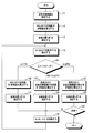
- FIG. 15 is a flowchart showing a focusing process procedure.
- FIG. 16 shows the relationship between the imaging range 130 and the ranges 131 and 132 for calculating the AF evaluation value.
- the focus target range is set by the photographer as described above (step 111).
- the set focus target range is indicated by reference numeral 132.
- the phase difference AF sensor 46 is controlled so that an output signal obtained from the center area (center portion) of the phase difference image sensor 43 is input to the evaluation value calculation circuit 44 and a phase difference AF evaluation value is calculated. (Step 112).
- the focus position (JP) is estimated in the control circuit 60 (step 113).
- the in-focus position may be estimated based on the phase difference AF evaluation value obtained and the AF evaluation value obtained from the optical path length difference AF sensor 55.
- the position of the focus lens 2 (referred to as FLP) is detected by the control circuit 60 (step 114).
- the position of the focus lens 2 is at the home position at the initial position, and when moving from the home position, a focus evaluation value signal (difference AF evaluation value is used to move the focus lens 2). Since the control signal 60 is input to the control circuit 60, it can be detected from the focus evaluation value signal.
- the difference ⁇
- step 114 The position of the focus lens 2 after the movement is detected (step 114), and the difference ⁇ between the position of the focus lens 2 and the estimated focus position is calculated again (step 115).
- the imaging range 130 of the phase difference image sensor 43 is obtained.
- the phase difference AF evaluation value is calculated based on the output signal obtained from the set focus target range 132 (see FIG. 16) (step 119).
- a focus position is estimated based on the calculated phase difference AF evaluation value (step 120).
- step 114 the position of the focus lens 2 after the movement is detected (step 114), and the difference ⁇ between the position of the focus lens 2 and the estimated focus position is calculated (step 115).
- the imaging range 130 of the first optical path length difference CCD 13 and the second optical path length difference CCD 14 constituting the optical path length difference AF sensor 55 is determined.
- the differential AF evaluation value is calculated based on the output signal obtained from the set focus target range 132 (see FIG. 16) (step 121).
- a focus position is estimated based on the calculated difference AF evaluation value (step 122). If the focus lens 2 is not in focus (NO in step 123), a signal representing the calculated differential AF evaluation value is given to the gain control amplification circuit 64 as a focus evaluation value signal, and the focus lens 2 is moved. (Step 118).
- the difference ⁇ is calculated as described above, and an evaluation value calculation process or the like according to the value is performed.
- the focus lens 2 is moved based on the difference AF evaluation value obtained from the optical path length difference AF sensor 55, so that it can be accurately positioned at the in-focus position.
- the phase difference AF evaluation value obtained from the central portion 131 of the imaging range 130 is used, and the calculated difference ⁇ is the first difference.
- the phase difference AF evaluation value obtained from the focusing target range 132 of the imaging range 131 is used.
- the central portion is gradually increased according to the magnitude of the difference ⁇ .
- the focus control described above may be performed using a phase difference AF evaluation value obtained from an extraction portion that moves from 131 to the position of the focus target range 132.
- the center coordinates of the central area 131 are (x0, y0), and the center coordinates of the focusing target range 132 are (x1, y1). Further, the center coordinates of the extracted portion are assumed to be (x, y).
- the size and shape of the central area 131, the focusing target range 132, and the extraction portion are preferably the same, but they are not necessarily the same.
- the above-mentioned difference ⁇ is [first threshold value Th1- ⁇ ] ( ⁇ is equal to or larger than 0 and smaller than the first threshold value Th1-second threshold value Th2) (fourth threshold value) ) Or more and less than [first threshold value Th1 + ⁇ ], the center coordinates (x, y) of the extracted portion can be obtained from Equations 1 and 2.
- the phase difference AF evaluation value obtained from the extracted portion of the central coordinates (x, y) obtained as described above is calculated. You can do it. However, when ⁇ is 0, the phase difference AF evaluation value obtained from the extracted portion of the center coordinates (x, y) is calculated in the process of step 116, and when ⁇ is 0, the center is determined in the process of step 119.
- the phase difference AF evaluation value obtained from the extracted portion of the coordinates (x, y) may be calculated.
- the first threshold value Th1, the second threshold value Th2, ⁇ , or ⁇ described above is not a single value but is farther from the in-focus position where the position of the focus lens 2 is estimated. Alternatively, it may be a different value depending on whether it is on the near side, or may be a different value depending on whether the estimated focus position itself is a distant position or a close position.
- the center position (x, y) of the extraction portion is linearly changed from the center position (x0, y0) of the central area to the center position (x1, y1) of the focus target range. It may be changed non-linearly or may be changed using a predetermined table.
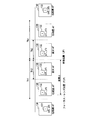
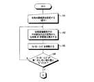
- FIG. 17 and FIG. 18 show another embodiment and are flowcharts showing a focusing process procedure.
- a focus target range is set by the photographer as shown in FIG. 5 (step 141).
- phase difference AF sensor 45 is driven, and the phase difference AF evaluation value is calculated based on the output signal of the central portion of the phase difference image sensor 43 (step 142).
- the focus lens 2 is moved so as to approach the in-focus position P0 based on the obtained phase difference AF evaluation value (step 143). Steps 102 and 103 are repeated until the focus lens 2 reaches the first threshold position P20 or P21 as described above (step 144).
- the focus lens 2 When the focus lens 2 reaches the first threshold position P20 or P21 (YES in step 144), the focus lens 2 is obtained from the range corresponding to the focus target range set by the cameraman on the light receiving surface of the phase difference image sensor 43. A phase difference AF evaluation value is calculated based on the output signal (step 145). Based on the calculated AF evaluation value, the focus lens 2 is moved so as to approach the in-focus position P0 (step 146). Steps 145 and 146 are repeated until the focus lens 2 reaches the second threshold position P30 or P31 (step 147).
- the focus lens 2 When the focus lens 2 reaches the second threshold position P30 or P31 (YES in step 147), the output signal of the focusing target range of the first optical path length difference AF CCD 12 and the second optical path length difference AF CCD 13 A differential AF evaluation value is calculated from (step 148). Based on the calculated difference AF evaluation value, the focus lens 2 is moved so as to approach the in-focus position P0 (step 149). The focus lens 2 is controlled so that the image within the focusing target range set by the user is focused.
Landscapes
- Engineering & Computer Science (AREA)
- Multimedia (AREA)
- Signal Processing (AREA)
- Physics & Mathematics (AREA)
- General Physics & Mathematics (AREA)
- Optics & Photonics (AREA)
- Human Computer Interaction (AREA)
- Automatic Focus Adjustment (AREA)
- Focusing (AREA)
- Studio Devices (AREA)
Abstract
Description
y=y1+(Δ-Th1+β)×(y0-y1)/(α+β)・・・式2
32 表示装置
33 タッチ・パネル
41 位相差センサ
42,51,52 評価値算出回路
46 位相差AFセンサ
55 光路長差AFセンサ
60 制御装置
61 切替制御回路
63 セレクタ
Claims (6)
- 撮像範囲のうち合焦させる合焦対象範囲を設定する合焦対象範囲設定部,
フォーカス・レンズを通って入射する光が瞳分割により複数に分けられた複数の被写体像が撮像面に結像される一つの位相差撮像素子から得られる出力信号にもとづいてピントのずれ量を示す第1の合焦評価値信号を出力する位相差AF部,
前記フォーカス・レンズを通って入射する光の光路において,光路長が互いに異なる位置に配置された第1の撮像素子および第2の撮像素子のそれぞれの出力信号にもとづいてピントのずれ量を示す第2の合焦評価値信号を出力する光路長差AF部,
前記第1の合焦評価値信号と前記第2の合焦評価値信号との少なくとも1つにもとづいて合焦位置を推定する合焦位置推定部,
前記フォーカス・レンズの位置を検出するフォーカス・レンズ位置検出部,
前記フォーカス・レンズの位置と前記合焦位置推定部により推定された合焦位置との差異を算出するフォーカス・レンズ位置評価部,
前記フォーカス・レンズの位置と,推定された合焦位置と,の差異が第1のしきい値よりも大きい場合は,前記位相差撮像素子の中央部分から得られる出力信号にもとづいて前記位相差AF部から出力された前記第1の合焦評価値信号を合焦評価値信号とし,前記差異が第2のしきい値よりも大きく前記第1のしきい値以下の場合は,前記位相差撮像素子の前記合焦対象範囲から得られる出力信号にもとづいて前記位相差AF部から出力された前記第1の合焦評価値信号を合焦評価値信号とし,前記差異が前記第2のしきい値以下の場合は,前記第1の撮像素子および前記第2の撮像素子の前記合焦対象範囲から得られる出力信号にもとづいて前記光路長差AF部に出力された前記第2の合焦評価値信号を合焦評価値信号とするAF切替部,ならびに
前記AF切替部において出力させられた合焦評価値信号にもとづいて前記フォーカス・レンズを移動させるフォーカス・レンズ移動制御部,
を備えたオート・フォーカス装置。 - 前記AF切替部は,
前記フォーカス・レンズ位置評価部において算出された前記差異が,前記第1のしきい値以上の第3のしきい値と,前記第2のしきい値以上であり,かつ前記第1のしきい値以下の第4のしきい値と,の間にある場合には,前記差異の大きさが大きいほど中央部分に近く,かつ前記差異の大きさが小さいほど合焦対象範囲に近くなるような前記位相差撮像素子の抽出部分から得られる出力信号にもとづいて前記位相差AF部から出力された前記第1の合焦評価値信号を合焦評価値信号とするものである,
請求項1に記載のオート・フォーカス装置。 - 前記合焦位置推定部は,
前記合焦対象範囲設定部により合焦対象範囲の設定後の最初の推定を,前記位相差撮像素子の中央部分から得られる出力信号にもとづいて前記位相差AF部から出力された前記第1の合焦評価値信号を合焦評価値信号とするものである,
請求項1または2に記載のオート・フォーカス装置。 - 前記位相差撮像素子がエリア・センサである,
請求項1から3のうち,いずれか一項に記載のオート・フォーカス装置。 - 前記合焦対象範囲,前記中央部分および前記抽出部分が同じ大きさである,
請求項1から4のうち,いずれか一項に記載のオート・フォーカス装置。 - 合焦対象範囲設定部が,撮像範囲のうち合焦させる合焦対象範囲を設定し,
位相差AF部が,フォーカス・レンズを通って入射する光が瞳分割により複数に分けられた複数の被写体像が撮像面に結像される一つの位相差撮像素子から得られる出力信号にもとづいてピントのずれ量を示す第1の合焦評価値信号を出力し,
光路長差AF部が,前記フォーカス・レンズを通って入射する光の光路において,光路長が互いに異なる位置に配置された第1の撮像素子および第2の撮像素子のそれぞれの出力信号にもとづいてピントのずれ量を示す第2の合焦評価値信号を出力し,
合焦位置推定部が,前記第1の合焦評価値信号と前記第2の合焦評価値信号との少なくとも1つにもとづいて合焦位置を推定し,
フォーカス・レンズ位置検出部が,前記フォーカス・レンズの位置を検出し,
フォーカス・レンズ位置評価部が,前記フォーカス・レンズの位置と前記合焦位置推定部により推定された合焦位置との差異を算出し,
AF切替部が,前記フォーカス・レンズの位置と,推定された合焦位置と,の差異が第1のしきい値よりも大きい場合は,前記位相差撮像素子の中央部分から得られる出力信号にもとづいて前記位相差AF部から出力された前記第1の合焦評価値信号を合焦評価値信号とし,前記差異が第2のしきい値よりも大きく前記第1のしきい値以下の場合は,前記位相差撮像素子の前記合焦対象範囲から得られる出力信号にもとづいて前記位相差AF部から出力された前記第1の合焦評価値信号を合焦評価値信号とし,前記差異が前記第2のしきい値以下の場合は,前記第1の撮像素子および前記第2の撮像素子の前記合焦対象範囲から得られる出力信号にもとづいて前記光路長差AF部に出力された前記第2の合焦評価値信号を合焦評価値信号とし,
フォーカス・レンズ移動制御部が,前記AF切替部において出力させられた合焦評価値信号にもとづいて前記フォーカス・レンズを移動させる,
オート・フォーカス装置の動作制御方法。
Priority Applications (3)
| Application Number | Priority Date | Filing Date | Title |
|---|---|---|---|
| CN201480032212.6A CN105264419B (zh) | 2013-06-06 | 2014-05-26 | 自动聚焦装置及其动作控制方法 |
| JP2015521391A JP5919436B2 (ja) | 2013-06-06 | 2014-05-26 | オート・フォーカス装置およびその動作制御方法 |
| US14/959,663 US9609204B2 (en) | 2013-06-06 | 2015-12-04 | Auto-focus device and method for controlling operation of same |
Applications Claiming Priority (2)
| Application Number | Priority Date | Filing Date | Title |
|---|---|---|---|
| JP2013-119413 | 2013-06-06 | ||
| JP2013119413 | 2013-06-06 |
Related Child Applications (1)
| Application Number | Title | Priority Date | Filing Date |
|---|---|---|---|
| US14/959,663 Continuation US9609204B2 (en) | 2013-06-06 | 2015-12-04 | Auto-focus device and method for controlling operation of same |
Publications (1)
| Publication Number | Publication Date |
|---|---|
| WO2014196389A1 true WO2014196389A1 (ja) | 2014-12-11 |
Family
ID=52008040
Family Applications (1)
| Application Number | Title | Priority Date | Filing Date |
|---|---|---|---|
| PCT/JP2014/063775 Ceased WO2014196389A1 (ja) | 2013-06-06 | 2014-05-26 | オート・フォーカス装置およびその動作制御方法 |
Country Status (4)
| Country | Link |
|---|---|
| US (1) | US9609204B2 (ja) |
| JP (1) | JP5919436B2 (ja) |
| CN (1) | CN105264419B (ja) |
| WO (1) | WO2014196389A1 (ja) |
Cited By (1)
| Publication number | Priority date | Publication date | Assignee | Title |
|---|---|---|---|---|
| JP2022078917A (ja) * | 2020-11-13 | 2022-05-25 | 株式会社三井光機製作所 | 光学像変換ユニット |
Families Citing this family (10)
| Publication number | Priority date | Publication date | Assignee | Title |
|---|---|---|---|---|
| WO2016203282A1 (en) * | 2015-06-18 | 2016-12-22 | The Nielsen Company (Us), Llc | Methods and apparatus to capture photographs using mobile devices |
| CN109690397B (zh) * | 2016-09-07 | 2021-02-12 | 富士胶片株式会社 | 模糊校正装置、模糊校正方法、记录介质、透镜装置及摄像装置 |
| US10165170B2 (en) * | 2017-03-06 | 2018-12-25 | Semiconductor Components Industries, Llc | Methods and apparatus for autofocus |
| JP6878111B2 (ja) * | 2017-04-21 | 2021-05-26 | ソニーモバイルコミュニケーションズ株式会社 | 固体撮像装置及び情報処理装置 |
| WO2019058974A1 (ja) * | 2017-09-20 | 2019-03-28 | 富士フイルム株式会社 | 撮像装置、撮像装置本体及び撮像装置の合焦制御方法 |
| CN111133355B (zh) * | 2017-09-28 | 2021-12-24 | 富士胶片株式会社 | 摄像装置、摄像装置的控制方法及存储介质 |
| US11062477B2 (en) * | 2018-04-20 | 2021-07-13 | Canon Kabushiki Kaisha | Image processing apparatus and its control method, imaging apparatus, image processing method, and storage medium |
| CN110702685A (zh) * | 2019-09-24 | 2020-01-17 | 深圳市华星光电半导体显示技术有限公司 | 显示面板的缺陷检测方法及缺陷检测系统 |
| JP2025033053A (ja) * | 2023-08-29 | 2025-03-13 | キヤノン株式会社 | 撮像装置、撮像装置の制御方法、およびプログラム |
| CN119395851A (zh) * | 2024-12-27 | 2025-02-07 | 立川(无锡)半导体设备有限公司 | 一种双路线传感器自动对焦系统 |
Citations (3)
| Publication number | Priority date | Publication date | Assignee | Title |
|---|---|---|---|---|
| JP2009003191A (ja) * | 2007-06-21 | 2009-01-08 | Olympus Corp | 撮像装置 |
| JP2009251342A (ja) * | 2008-04-08 | 2009-10-29 | Panasonic Corp | 撮像装置、フォーカス制御方法、プログラムおよび集積回路 |
| JP2010243843A (ja) * | 2009-04-07 | 2010-10-28 | Fujifilm Corp | オートフォーカスシステム |
Family Cites Families (8)
| Publication number | Priority date | Publication date | Assignee | Title |
|---|---|---|---|---|
| JP2007248782A (ja) * | 2006-03-15 | 2007-09-27 | Olympus Imaging Corp | 焦点調節装置およびカメラ |
| JP4946311B2 (ja) * | 2006-09-25 | 2012-06-06 | 株式会社ニコン | 焦点調節装置、カメラ |
| JP4962021B2 (ja) * | 2007-01-26 | 2012-06-27 | 株式会社ニコン | 焦点調節装置および撮像装置 |
| JP2009036986A (ja) * | 2007-08-01 | 2009-02-19 | Olympus Imaging Corp | 撮影装置および撮影装置の制御方法 |
| JP2009069170A (ja) * | 2007-08-22 | 2009-04-02 | Olympus Imaging Corp | 撮影装置および撮影装置の制御方法 |
| KR101137615B1 (ko) * | 2010-01-12 | 2012-04-19 | 삼성전자주식회사 | 디지털 카메라의 자동 초점 조정 방법 및 장치 |
| JP5821187B2 (ja) * | 2010-12-24 | 2015-11-24 | ソニー株式会社 | 撮像システム、マウントアダプタ、撮像装置、およびプログラム |
| US9503645B2 (en) * | 2012-05-24 | 2016-11-22 | Mediatek Inc. | Preview system for concurrently displaying multiple preview images generated based on input image generated by image capture apparatus and related preview method thereof |
-
2014
- 2014-05-26 JP JP2015521391A patent/JP5919436B2/ja not_active Expired - Fee Related
- 2014-05-26 CN CN201480032212.6A patent/CN105264419B/zh not_active Expired - Fee Related
- 2014-05-26 WO PCT/JP2014/063775 patent/WO2014196389A1/ja not_active Ceased
-
2015
- 2015-12-04 US US14/959,663 patent/US9609204B2/en not_active Expired - Fee Related
Patent Citations (3)
| Publication number | Priority date | Publication date | Assignee | Title |
|---|---|---|---|---|
| JP2009003191A (ja) * | 2007-06-21 | 2009-01-08 | Olympus Corp | 撮像装置 |
| JP2009251342A (ja) * | 2008-04-08 | 2009-10-29 | Panasonic Corp | 撮像装置、フォーカス制御方法、プログラムおよび集積回路 |
| JP2010243843A (ja) * | 2009-04-07 | 2010-10-28 | Fujifilm Corp | オートフォーカスシステム |
Cited By (2)
| Publication number | Priority date | Publication date | Assignee | Title |
|---|---|---|---|---|
| JP2022078917A (ja) * | 2020-11-13 | 2022-05-25 | 株式会社三井光機製作所 | 光学像変換ユニット |
| JP7583987B2 (ja) | 2020-11-13 | 2024-11-15 | 株式会社三井光機製作所 | 光学像変換ユニット |
Also Published As
| Publication number | Publication date |
|---|---|
| JPWO2014196389A1 (ja) | 2017-02-23 |
| JP5919436B2 (ja) | 2016-05-18 |
| CN105264419A (zh) | 2016-01-20 |
| CN105264419B (zh) | 2017-09-22 |
| US20160094781A1 (en) | 2016-03-31 |
| US9609204B2 (en) | 2017-03-28 |
Similar Documents
| Publication | Publication Date | Title |
|---|---|---|
| JP5919436B2 (ja) | オート・フォーカス装置およびその動作制御方法 | |
| US9411128B2 (en) | Automatic focusing apparatus with cyclic pattern determination | |
| JP5379739B2 (ja) | レンズ装置 | |
| US11378774B2 (en) | Lens control apparatus, imaging apparatus including lens control apparatus, and lens control method | |
| JP6071744B2 (ja) | 自動焦点調整装置及びそれを有するレンズ装置、撮像装置 | |
| JP2015194706A5 (ja) | ||
| JP2016142925A (ja) | 撮像装置およびその制御方法、プログラム、記憶媒体 | |
| US10999491B2 (en) | Control apparatus, image capturing apparatus, control method, and storage medium | |
| WO2012035877A1 (ja) | 撮影装置 | |
| JP2019078843A (ja) | 像ブレ補正装置およびその制御方法、撮像装置 | |
| JP2016197231A5 (ja) | ||
| US11089222B2 (en) | Shake correction device, shake correction method, shake correction program, lens device, and imaging device | |
| JP2008268815A (ja) | 自動合焦装置 | |
| KR101737260B1 (ko) | 영상간 피사계 심도 차이에서 깊이를 추출하는 카메라 시스템 및 그 동작 방법 | |
| JP2016114614A (ja) | オート・フォーカス装置およびその動作制御方法 | |
| JP2011123339A (ja) | レンズシステム | |
| JP2018180135A (ja) | 撮像装置 | |
| US10530985B2 (en) | Image capturing apparatus, image capturing system, method of controlling image capturing apparatus, and non-transitory computer-readable storage medium | |
| JP2016106242A (ja) | オート・フォーカス装置およびその動作制御方法 | |
| KR101930196B1 (ko) | 자동 초점 조절 기능 및/또는 깊이 추정 기능을 갖는 멀티 애퍼쳐 카메라 시스템 | |
| KR20140108015A (ko) | 카메라 모듈 | |
| JP2010072333A (ja) | 合焦レンズ装置 | |
| JP2016142778A (ja) | 撮像装置 | |
| JP2018180134A (ja) | 撮像装置 | |
| JP2018105948A (ja) | 焦点検出方法、および撮像装置 |
Legal Events
| Date | Code | Title | Description |
|---|---|---|---|
| WWE | Wipo information: entry into national phase |
Ref document number: 201480032212.6 Country of ref document: CN |
|
| 121 | Ep: the epo has been informed by wipo that ep was designated in this application |
Ref document number: 14807414 Country of ref document: EP Kind code of ref document: A1 |
|
| ENP | Entry into the national phase |
Ref document number: 2015521391 Country of ref document: JP Kind code of ref document: A |
|
| NENP | Non-entry into the national phase |
Ref country code: DE |
|
| 122 | Ep: pct application non-entry in european phase |
Ref document number: 14807414 Country of ref document: EP Kind code of ref document: A1 |