WO2014196273A1 - 入力受付装置 - Google Patents
入力受付装置 Download PDFInfo
- Publication number
- WO2014196273A1 WO2014196273A1 PCT/JP2014/060696 JP2014060696W WO2014196273A1 WO 2014196273 A1 WO2014196273 A1 WO 2014196273A1 JP 2014060696 W JP2014060696 W JP 2014060696W WO 2014196273 A1 WO2014196273 A1 WO 2014196273A1
- Authority
- WO
- WIPO (PCT)
- Prior art keywords
- touch
- input content
- determination unit
- touch panel
- determined
- Prior art date
- Legal status (The legal status is an assumption and is not a legal conclusion. Google has not performed a legal analysis and makes no representation as to the accuracy of the status listed.)
- Ceased
Links
Images









Classifications
-
- G—PHYSICS
- G06—COMPUTING OR CALCULATING; COUNTING
- G06F—ELECTRIC DIGITAL DATA PROCESSING
- G06F3/00—Input arrangements for transferring data to be processed into a form capable of being handled by the computer; Output arrangements for transferring data from processing unit to output unit, e.g. interface arrangements
- G06F3/01—Input arrangements or combined input and output arrangements for interaction between user and computer
- G06F3/048—Interaction techniques based on graphical user interfaces [GUI]
- G06F3/0481—Interaction techniques based on graphical user interfaces [GUI] based on specific properties of the displayed interaction object or a metaphor-based environment, e.g. interaction with desktop elements like windows or icons, or assisted by a cursor's changing behaviour or appearance
- G06F3/0482—Interaction with lists of selectable items, e.g. menus
-
- G—PHYSICS
- G06—COMPUTING OR CALCULATING; COUNTING
- G06F—ELECTRIC DIGITAL DATA PROCESSING
- G06F3/00—Input arrangements for transferring data to be processed into a form capable of being handled by the computer; Output arrangements for transferring data from processing unit to output unit, e.g. interface arrangements
- G06F3/01—Input arrangements or combined input and output arrangements for interaction between user and computer
- G06F3/048—Interaction techniques based on graphical user interfaces [GUI]
- G06F3/0487—Interaction techniques based on graphical user interfaces [GUI] using specific features provided by the input device, e.g. functions controlled by the rotation of a mouse with dual sensing arrangements, or of the nature of the input device, e.g. tap gestures based on pressure sensed by a digitiser
- G06F3/0488—Interaction techniques based on graphical user interfaces [GUI] using specific features provided by the input device, e.g. functions controlled by the rotation of a mouse with dual sensing arrangements, or of the nature of the input device, e.g. tap gestures based on pressure sensed by a digitiser using a touch-screen or digitiser, e.g. input of commands through traced gestures
Definitions
- the present invention relates to an input reception device.
- an input reception device having a touch panel is known as an input reception device applied to an in-vehicle navigation system or the like (see, for example, Patent Documents 1 and 2).
- Patent Document 1 when an icon for changing a setting value displayed on the screen is touched, the setting value changes according to the touched time, and the number of vibrations of the touch panel changes. Thereby, the operator can recognize the amount of change in the set value.
- an object of the present invention is to provide an input reception device that can be safely operated even while driving without requiring an operator to watch the operation screen.
- a display unit capable of displaying an operation screen, a touch panel disposed on the display unit, a touch determination unit that determines whether or not the touch panel has been touched.
- a display control unit that displays an operation screen on the display unit, and an input content determination unit that determines the input content according to the moving direction of the touch position from the base point, based on the touch position when it is determined that the touch is performed
- an input receiving device characterized by comprising:
- the input content determination unit when the input content determination unit is in a non-touch state after the touch position is moved, the input content is confirmed, and after the touch position is moved, before the non-touch state is entered, The input content may be canceled when the movement further in the direction opposite to the movement direction of the touch position.
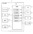
- FIG. 1 is a block diagram showing an example of an input receiving apparatus according to an embodiment of the present invention.
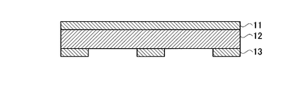
- FIG. 2 is a cross-sectional view illustrating an example of the configuration of the display unit, the touch panel, and the vibration unit according to the embodiment of the present invention.
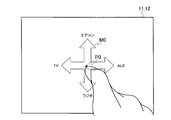
- FIG. 3 is a schematic diagram showing a state in which the touch panel according to the embodiment of the present invention is touched.
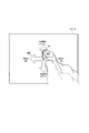
- FIG. 4 is a schematic diagram showing an example of an operation screen (menu screen) according to the embodiment of the present invention.
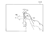
- FIG. 5 is a schematic diagram showing a state in which a finger is slid on the touch panel according to the embodiment of the present invention.
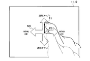
- FIG. 6 is a schematic diagram showing an example of a screen for changing the set temperature of the air conditioner according to the embodiment of the present invention.
- FIG. 1 is a block diagram showing an example of an input receiving apparatus according to an embodiment of the present invention.
- FIG. 2 is a cross-sectional view illustrating an example of the configuration of the display unit, the touch panel
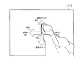
- FIG. 7 is a schematic diagram showing a state in which a finger is slid when a screen for changing the set temperature of the air conditioner according to the embodiment of the present invention is displayed.
- FIG. 8 is a schematic diagram showing an example of a radio channel selection screen according to the embodiment of the present invention.
- FIG. 9 is a schematic diagram showing an example of a music selection screen of the audio device according to the embodiment of the present invention.
- FIG. 10 is a schematic diagram showing an example of the channel selection screen of the television according to the embodiment of the present invention.
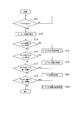
- FIG. 11 is a flowchart for explaining an example of the input receiving method according to the embodiment of the present invention.
- FIG. 12 is a flowchart for explaining an example of the AM channel selection method according to the embodiment of the present invention.
- FIG. 13 is a schematic diagram showing an example of an AM channel selection screen according to the embodiment of the present invention.
- FIG. 14 is a flowchart for explaining an example of the FM channel selection method according to the embodiment of the present invention.
- FIG. 15 is a schematic diagram showing an example of an FM channel selection screen according to the embodiment of the present invention.
- FIG. 16 is a flowchart for explaining an example of a radio volume adjustment method according to the embodiment of the present invention.
- FIG. 17 is a schematic diagram showing an example of a radio volume adjustment screen according to the embodiment of the present invention.
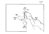
- FIG. 18 is a schematic diagram illustrating an example of a menu screen according to a modification of the embodiment of the present invention.
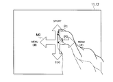
- FIG. 19 is a schematic diagram illustrating an example of a travel mode change screen according to a modification of the embodiment of the present invention.
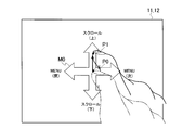
- FIG. 20 is a schematic diagram illustrating an example of a map scroll change screen according to a modification of the embodiment of the present invention.
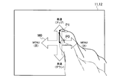
- FIG. 21 is a schematic diagram illustrating an example of an approach warning speed change screen according to a modification of the embodiment of the present invention.
- FIG. 22 is a schematic diagram illustrating an example of a screen for changing the display position of the head-up display according to the modification of the embodiment of the present invention.
- ⁇ Input reception device> As an application example of the input reception device 1 according to the embodiment of the present invention, a case where the present invention is applied to an in-vehicle system in which various in-vehicle devices are mounted as shown in FIG. 1 will be described.
- the input reception device 1 is connected with a radio 2, an air conditioner 3, a television 4 and an audio device 5 as in-vehicle devices.
- the radio 2, the air conditioner 3, the television 4, and the audio device 5 receive a control signal from the input reception device 1 and execute an operation according to the control signal.
- the radio 2, the air conditioner 3, the television 4, and the audio device 5 are described as examples of in-vehicle devices.
- the present invention is not particularly limited thereto, and various in-vehicle devices such as a navigation device can be applied. It is.
- the input reception device 1 receives an instruction from the operator.
- the input reception device 1 includes a control unit 10, a touch panel 11, a display unit 12, a vibration unit 13, and a storage unit 14 connected to the control unit 10.
- the touch panel 11 is disposed on the front surface of the display unit 12 (on the display unit 12), and the vibration unit 13 is disposed on the back surface of the display unit 12.
- the touch panel 11 is a transmissive touch panel such as a resistive film method, a capacitance method, an ultrasonic surface acoustic wave method, an optical method, an electromagnetic induction method, and the like, detects a touch operation with a finger or the like and a position thereof, and detects a detection signal. Is output to the control unit 10.
- the display unit 12 is a liquid crystal panel, for example, and receives a control signal from the control unit 10 and displays various operation screens according to the control signal.
- the vibration unit 13 is an actuator, for example, and receives a control signal from the control unit 10 and applies vibration to the touch panel 11 according to the control signal.
- the storage unit 14 is, for example, a semiconductor memory, and stores a threshold value and the like used when the input reception device 1 operates.
- control unit 10 a microcomputer mainly composed of a central processing unit (CPU), ROM, RAM, and I / O interface can be used.
- the control unit 10 includes a touch determination unit 101, a display control unit 102, an input content determination unit 103, a vibration control unit 104, and a device control unit 105 when the processing executed by the control unit 10 is functionally captured.
- the touch determination unit 101 determines whether an arbitrary position on the touch panel 11 is touched by the operator based on a detection signal from the touch panel 11.
- the display control unit 102 causes the display unit 12 to display various operation screens when it is determined that the touch determination unit 101 has touched. Further, the display control unit 102 switches the operation screen displayed on the display unit 12 according to the determination result of the input content by the input content determination unit 103.
- the input content determination unit 103 determines the input content according to the moving direction of the subsequent touch position from the base point, with the first touch position when it is determined that the touch determination unit 101 determines that the touch has been made as the base point.
- the vibration control unit 104 vibrates the vibration unit 13 under a vibration condition corresponding to the input content determination result by the input content determination unit 103.
- the vibration conditions include vibration time, vibration pattern, frequency, vibration intensity (amplitude), or a combination thereof.
- the device control unit 105 outputs a control signal for changing the set value for the radio 2, the air conditioner 3, the television 4, and the audio device 5 that are in-vehicle devices in accordance with the determination result of the input content by the input content determination unit 103. Output.
- an arbitrary position P0 on the touch panel 11 is touched by the operator. Based on the detection signal from the touch panel 11, the touch determination unit 101 determines whether or not a touch has been made regardless of the arbitrary position P0 on the touch panel 11. Further, the position P ⁇ b> 0 when it is determined that the touch is determined by the touch determination unit 101 is stored in the storage unit 14.
- the display control unit 102 causes the display unit 12 to display an operation screen (menu screen) for selecting a setting change target.
- a cross arrow mark M0 is displayed at the position P0, and at the end of each arrow, "air conditioner” for selecting the air conditioner 3, "TV” for selecting the television 4, and the radio 2 are displayed.
- Character strings “radio” for selecting and “AUX” for selecting the audio device 5 are displayed. Instead of these character strings, a figure or icon indicating a setting change target may be displayed at the end of each arrow.
- the operator can easily recognize that the setting change target can be selected by moving his / her finger up / down / left / right. For example, when the operator wants to select the air conditioner 3, as shown in FIG. 5, after touching the touch panel 11, the operator can select the air conditioner 3 by moving (sliding) his / her finger upward. . At this time, the operator does not need to touch a specific position on the touch panel 11 in order to select the setting change target, but only moves the finger in the direction of the arrow corresponding to the setting change target. It can be easily recognized that the target can be selected.
- the shape of the mark M0 is not particularly limited, and may be, for example, four arrows indicating up, down, left, and right. Further, only the setting change target that can be selected at the top, bottom, left, and right of the position P0 may be displayed without displaying the mark M0.
- the display control unit 102 may display the mark M0 so that the mark M0 is positioned at a default position (for example, the center of the touch panel 11) different from the position P0.
- the input content determination unit 103 calculates a movement amount (distance) from the base point that is the touch position to the touch position P1 after the movement, based on the detection signal from the touch panel 11 as a base point. Further, the input content determination unit 103 compares the calculated movement amount with a threshold value (for example, 10 mm) stored in the storage unit 14, and if the movement amount of the touch position is equal to or greater than the threshold value, the touch position moves in that direction. It is determined that Furthermore, the input content determination unit 103 determines which of the radio 2, the air conditioner 3, the television 4, or the audio device 5 has been selected by the operator according to the moving direction of the touch position.
- a threshold value for example, 10 mm
- the movement amount is calculated separately for each direction component. That is, the movement amount in the X-axis direction and the movement amount in the Y-axis direction are calculated with the left-right direction as the X-axis and the up-down direction as the Y-axis. A case where the threshold is set to 10 mm, for example, will be described.
- the right It is determined that the direction has been selected. In the example of FIG. 5, it is determined that the audio device 5 has been selected.
- the left It is determined that the direction has been selected. In the example of FIG. 5, it is determined that the television 4 has been selected.
- the movement amount in the Y-axis direction is plus 10 mm or more (movement of 10 mm or more in the downward direction) and the movement amount in the X-axis direction is less than 10 mm (the absolute value of the movement amount in the left-right direction is less than 10 mm), It is determined that the direction has been selected. In the example of FIG. 5, it is determined that the radio 2 has been selected.
- the direction in the Y-axis direction is minus 10 mm or more (moving 10 mm or more in the upward direction) and the movement amount in the X-axis direction is less than 10 mm (the absolute value of the movement amount in the left-right direction is less than 10 mm), It is determined that the direction has been selected. In the example of FIG. 5, it is determined that the air conditioner 3 has been selected.
- the direction is not determined under the above conditions for the movement of the touch position, it may be determined that the touch position has not moved, or the amount of movement in either the X-axis or Y-axis direction May be used for determination, and it may be determined that a predetermined direction is selected.
- the input content determination unit 103 does not immediately determine the input content, but determines the input content when the finger is subsequently released (non-touch state). Also good. Furthermore, when the finger moves in a direction opposite to the direction in which the finger has moved before leaving, the determination result of the input content based on the previous movement may be canceled.
- the vibration control unit 104 vibrates the vibration unit 13 when the input content determination unit 103 determines that the radio 2, the air conditioner 3, the television 4, or the audio device 5 is selected. Thus, the operator can tactilely recognize that the setting change target has been selected without using vision.
- the vibration unit 13 may generate vibrations with different vibration conditions depending on the type of the selected setting change target. Thus, the operator can tactilely recognize whether or not the intended setting change target has been selected without using vision.
- the touch determination unit 101 determines that the touch panel 11 is touched based on a detection signal from the touch panel 11.
- the display control unit 102 sets the set temperature of the air conditioner 3 as shown in FIG. A change screen (operation screen) is displayed on the display unit 12.
- a cross arrow mark M0 is displayed at position P0.
- a character string corresponding to a process selected when the touch position is moved in that direction is displayed at the tip of each arrow of the arrow mark M0.
- “Return)” and “MENU (next)” for moving to the air volume setting screen are displayed in the right direction.
- the operator can change the set temperature by moving (sliding) the finger up and down from the position P0 instead of touching a specific position on the touch panel 11.
- moving (sliding) the finger in the left-right direction from the position P0 it is possible to shift to a setting menu screen different from the set temperature.
- the input content determination unit 103 determines the moving direction of the subsequent touch position using the initial position P0 as a base point. Specifically, the input content determination unit 103 compares the movement amount from the base point to the touch position P1 after the movement with a threshold value (for example, 10 mm) stored in the storage unit 14, and the movement amount of the touch position is equal to or greater than the threshold value. If so, it is determined that the touch position has moved in that direction. Furthermore, the input content determination unit 103 determines the input content according to the moving direction of the touch position.
- a threshold value for example, 10 mm
- the input content determination unit 103 may determine the input content when the finger is released (non-touch state) without immediately determining the input content when the touch position is moved. In this case, when the finger is further moved in the direction opposite to the direction moved before the finger is released, the changed set value may be canceled.
- the input content determination unit 103 measures the time that the finger is touched after the touch position moves and then changes the set value continuously every time a certain time (for example, 1 second) elapses. May be. In other words, the longer the touched time until the finger is released, the larger the set value changes. On the other hand, the shorter the touched time until the finger is released, the shorter the set value is. It may not be changed.
- the vibration control unit 104 changes the vibration condition in stages each time the set value is changed. For example, as the set temperature of the air conditioner 3 increases, it is vibrated with a larger amplitude. Thereby, the operator can grasp
- the input content determination unit 103 when the input content determination unit 103 continuously changes the set value and then moves further in the direction opposite to the direction in which the finger moved before the finger leaves, the input content determination unit 103 further changes the set value according to the direction. May be.
- the set temperature of the air conditioner 3 is excessively increased by pressing and holding the upward direction in FIG. 7, the downward direction when the finger is moved downward by a threshold value or more (for example, 10 mm) with the touch position P1 at that time as a base point It is possible to switch to the mode for lowering the set temperature.
- the input content determination unit 103 may determine the input content according to the movement amount (distance) of the touch position with the initial position P0 as a base point.
- the longer the amount of movement (distance) of the touch position the larger the set value changes.
- the shorter the amount of movement (distance) of the touch position the smaller the set value decreases. May be.
- the set temperature of the air conditioner 3 when the set temperature of the air conditioner 3 is changed, the set temperature may be increased or decreased as the touch position movement amount increases. Specifically, the set temperature may be increased or decreased by 1 ° C. if the movement amount of the touch position is 10 mm or more and less than 20 mm, and the set temperature may be increased or decreased by 2 ° C. if the movement amount of the touch position is 20 mm or more.
- the device control unit 105 transmits a control signal for changing the set value to the air conditioner 3 in accordance with the determination result of the input content by the input content determination unit 103.
- the present invention is not particularly limited to this, and settings for various in-vehicle devices can be changed.
- the display control unit 102 displays the channel selection screen of the radio 2 illustrated in FIG. 8. Is displayed. As shown in FIG. 8, “channel selection (up)” and “channel selection (down)” for selecting a broadcast station are respectively displayed at the tip of the vertical arrow of the arrow mark M0.
- the display control unit 102 selects the music of the audio device 5 shown in FIG. Display the screen. As shown in FIG. 9, “selection of music (next)” and “selection of music (previous)” for changing the music are displayed at the tip of the vertical arrow M0.
- the display control unit 102 displays the music selection screen of the television 4 shown in FIG. indicate. As shown in FIG. 10, “channel selection (up)” and “channel selection (down)” for changing the music are respectively displayed at the tip of the vertical arrow of the arrow mark M0.
- the device control unit 105 transmits a control signal for changing the set value to the radio 2, the air conditioner 3, the television 4, or the audio device 5 that is a vehicle-mounted device in accordance with the determination result of the input content by the input content determination unit 103. To do.
- step S ⁇ b> 11 the touch determination unit 101 determines whether an arbitrary position P ⁇ b> 0 of the touch panel 11 has been touched based on a detection signal from the touch panel 11. If it is determined that the touch has been made, the process proceeds to step S12.
- step S12 the display control unit 102 causes the display unit 12 to display an operation screen (menu screen) as shown in FIG.
- the operator can select the setting change target by sliding his / her finger in any of the up / down / left / right directions.
- the input content determination unit 103 determines whether the touch position has moved in the vertical and horizontal directions with the initial position P0 as a base point. Then, it is determined that the radio 2, the air conditioner 3, the television 4, or the audio device 5 has been selected according to the moving direction of the touch position, and the process proceeds to steps S14, S16, S18, and S20 to perform setting change processing.
- setting change processing (steps) of the radio 2, the air conditioner 3, the television 4, and the audio device 5 is performed according to the movement direction of the touch position being downward, upward, rightward, and leftward, respectively. S14, S16, S18, S20) are shown.
- step S31 the touch determination unit 101 determines whether an arbitrary position P0 of the touch panel 11 is touched based on the detection signal from the touch panel 11. When it is determined that the touch has been made, the process proceeds to step S32.
- step S32 the display control unit 102 displays an AM channel selection screen as shown in FIG. In FIG. 13, “AM channel selection (up)” and “AM channel selection (down)” for selecting AM broadcast stations in the vertical direction are displayed.
- the input content determination unit 103 determines whether the touch position has moved in the vertical and horizontal directions with the initial position P0 as a base point.
- step S34 the input content determination unit 103 continuously tunes up at regular time intervals, and the vibration control unit 104 changes the vibration conditions step by step, for example, so that the amplitude becomes larger. 13 is vibrated. If it is determined in step S35 that the finger has been released, the process proceeds to step S36, and the input content determination unit 103 determines the set value at that time.
- step S38 the input content determination unit 103 continuously tunes down at regular time intervals, and the vibration control unit 104 changes the vibration conditions step by step, for example, so that the amplitude becomes smaller. 13 is vibrated. If it is determined in step S39 that the finger has been removed, the process proceeds to step S40, and the input content determination unit 103 determines the set value at that time.
- step S41 determines whether it has moved to the right. If it is determined in step S41 that it has moved to the right, the process proceeds to step S42 and FM channel selection is set.
- step S43 If it is determined in step S43 that the movement has been made to the left, the process proceeds to step S44, the process returns to the menu selection process, and the same procedure as that shown in FIG. 11 is executed.
- step S51 the touch determination unit 101 determines whether or not an arbitrary position P0 of the touch panel 11 has been touched based on the detection signal from the touch panel 11. When it is determined that the touch has been made, the process proceeds to step S52.
- step S52 the display control unit 102 displays an FM channel selection screen as shown in FIG. In FIG. 15, “FM channel selection (up)” and “FM channel selection (down)” for selecting FM broadcast stations in the vertical direction are displayed.
- the input content determination unit 103 determines whether the touch position has moved up, down, left, or right from the initial position P0.
- step S53 If it is determined in step S53 that it has moved upward, the process proceeds to step S54.
- step S54 the input content determination unit 103 continuously tunes up at regular time intervals, and the vibration control unit 104 changes the vibration conditions step by step, for example, so that the amplitude becomes larger. 13 is vibrated. If it is determined in step S55 that the finger has been released, the process proceeds to step S56, and the input content determination unit 103 determines the set value at that time.
- step S57 if it is determined in step S57 that it has moved downward, the process proceeds to step S58.
- step S58 the input content determination unit 103 continuously tunes down at regular time intervals, and the vibration control unit 104 changes the vibration conditions step by step, for example, so that the amplitude becomes smaller. 13 is vibrated. If it is determined in step S59 that the finger has been released, the process proceeds to step S60, and the input content determination unit 103 determines the set value at that time.
- step S61 determines whether it has moved to the right. If it is determined in step S61 that it has moved to the right, the process proceeds to step S62, and the volume of the radio 2 is adjusted.
- step S63 If it is determined in step S63 that it has moved to the left, the process proceeds to step S64, returns to the AM channel selection process, and a procedure similar to the procedure shown in FIG. 12 is executed.
- step S ⁇ b> 71 the touch determination unit 101 determines whether an arbitrary position P ⁇ b> 0 of the touch panel 11 has been touched based on the detection signal from the touch panel 11. When it is determined that the touch has been made, the process proceeds to step S72.
- step S72 the display control unit 102 displays a volume adjustment screen as shown in FIG. In FIG. 17, “volume (up)” and “volume (down)” for adjusting the volume in the vertical direction are displayed.
- the input content determination unit 103 determines whether the touch position has moved in the vertical and horizontal directions with the initial position P0 as a base point.
- step S73 If it is determined in step S73 that it has moved upward, the process proceeds to step S74.
- step S74 the input content determination unit 103 continuously increases the volume at regular time intervals, and the vibration control unit 104 changes the vibration conditions stepwise, for example, so that the amplitude becomes larger. Vibrate. If it is determined in step S75 that the finger has been removed, the process proceeds to step S76, and the input content determination unit 103 determines the set value at that time.
- step S77 if it is determined in step S77 that it has moved downward, the process proceeds to step S78.
- step S78 the input content determination unit 103 continuously decreases the volume at regular intervals, and the vibration control unit 104 changes the vibration condition stepwise, for example, so that the amplitude becomes smaller. Vibrate. If it is determined in step S79 that the finger has been released, the process proceeds to step S80, and the input content determination unit 103 determines the set value at that time.
- step S81 determines whether it has moved to the right. If it is determined in step S81 that it has moved to the right, the process proceeds to step S82, the process returns to the menu selection process, and the same procedure as that shown in FIG. 11 is executed.
- step S83 If it is determined in step S83 that it has moved to the left, the process proceeds to step S84, returns to the FM channel selection process, and the same procedure as that shown in FIG. 15 is executed.
- steps S41 to S44 in FIG. 12 steps S61 to S64 in FIG. 14, and steps S81 to S84 in FIG. 16, the operator can perform the menu shown in FIG. 4 only by moving the touch position left and right.
- the setting screen can be switched between the screen, the AM channel selection screen shown in FIG. 13, the FM channel selection screen shown in FIG. 15, and the volume adjustment screen shown in FIG.
- the input content is determined according to the moving direction of the touch position with the position P0 as a base point.
- the operator can operate by touching an arbitrary position P0 and moving his / her finger. Therefore, the operator does not need to touch the icon or a specific position on the screen, so that it is not necessary to gaze at the touch panel 11, and it is not necessary to shift the line of sight from the foreground during driving.
- the operation can be performed with the minimum movement without largely moving the driving posture. Therefore, even if it is driving
- the input content determination unit 103 configured to determine the input content when the operator's finger is released from the touch panel 11 after the touch position is moved, the operator can touch the touch position before the finger is released. When the touch position is further moved in the direction opposite to the moving direction, the input content determination unit 103 is configured to cancel the input content, so that the operator can easily cancel the input content once determined. .
- the vibration condition is changed stepwise to vibrate, so that the tactile change due to the vibration of the touch panel 11 and the change in the set value can be detected. Can take. Therefore, the operator can tactilely recognize the change in the set value without using vision. The operator can intuitively grasp the change in the set value.
- ⁇ Modification> As a modification of the embodiment of the present invention, a case where a plurality of menu screens are switched will be described.
- a case where a menu screen (second menu screen) as shown in FIG. 18 is displayed together with the menu screen (first menu screen) shown in FIG. 4 will be described.
- the display control unit 102 displays the travel mode change screen shown in FIG. 19. As shown in FIG. 19, “SPORT” for selecting sport driving and “ECO” for selecting eco driving are displayed at the tip of the arrow in the vertical direction of the arrow mark M0.
- the display control unit 102 displays the map scroll change screen shown in FIG. As shown in FIG. 20, "scroll (up)” and “scroll (down)” for scrolling the map up and down are displayed at the tip of the up and down arrow of the arrow mark M0.
- the display control unit 102 displays an approach warning speed change screen shown in FIG. As shown in FIG. 21, “vehicle speed (up)” and “vehicle speed (down)” for increasing and decreasing the speed at which the approach alarm is activated are respectively displayed at the tip of the vertical arrow of the arrow mark M0. .
- the display control unit 102 displays a screen for changing the display position of the head-up display shown in FIG. As shown in FIG. 22, “display position (up)” and “display position (down)” for moving up and down the display position of the HUD are displayed at the tip of the arrow in the vertical direction of the arrow mark M0. .
- Switching between the first menu screen and the second menu screen is a different operation from the movement of the touch position in the vertical and horizontal directions with the initial touch position as a base point, for example, an operation for rotating one or two fingers. It can be executed by the determination by the unit 103.
- setting change items are displayed in the vertical direction and menu selection items are displayed in the horizontal direction as shown in FIG.
- menu selection items may be displayed in the vertical direction
- setting change items may be displayed in the horizontal direction
- the setting change items may be displayed only in the vertical direction, and nothing may be displayed in the horizontal direction.
- different setting change items for example, air volume and temperature of an air conditioner
- the touch panel 11 is touched with a finger.
- the present invention is not particularly limited thereto, and the touch panel 11 may be touched with a dedicated pen or the like.
- the system to which the input receiving apparatus 1 according to the embodiment of the present invention is applied is not limited to an automobile, but a ship, an aircraft, a machine tool, a construction machine, an industrial machine, a manufacturing apparatus, a steel refining furnace, a nuclear reactor Needless to say, the present invention can also be applied to various mechanical devices and equipment with high temperature, high pressure, and high energy.
Landscapes
- Engineering & Computer Science (AREA)
- General Engineering & Computer Science (AREA)
- Theoretical Computer Science (AREA)
- Human Computer Interaction (AREA)
- Physics & Mathematics (AREA)
- General Physics & Mathematics (AREA)
- Position Input By Displaying (AREA)
- User Interface Of Digital Computer (AREA)
Abstract
操作画面を表示可能な表示部(12)と、表示部(12)上に配置されたタッチパネル(11)と、タッチパネル(11)がタッチされたか否かを判定するタッチ判定部(101)と、タッチされたと判定された場合に表示部(12)に操作画面を表示させる表示制御部(102)と、タッチされたと判定されたときのタッチ位置を基点として、タッチ位置の移動方向に応じて入力内容を判定する入力内容判定部(103)とを備える。
Description
本発明は、入力受付装置に関する。
従来、車載用ナビゲーションシステム等に適用される入力受付装置として、タッチパネルを有する入力受付装置が知られている(例えば、特許文献1及び2参照。)
特許文献1に記載の装置では、画面上に表示された設定値を変更するアイコンをタッチすると、タッチしている時間に応じて設定値が変化するとともに、タッチパネルの振動回数が変化する。これにより、操作者は設定値の変化量を認識することができる。
特許文献1に記載の装置では、画面上に表示された設定値を変更するアイコンをタッチすると、タッチしている時間に応じて設定値が変化するとともに、タッチパネルの振動回数が変化する。これにより、操作者は設定値の変化量を認識することができる。
一方、特許文献2に記載の装置では、タッチパネルの画面上に表示された図形であって、設定値を変更するスイッチを模擬した図形の特定の位置をタッチすると、タッチした位置に応じて設定値を変更するとともに、その設定値に応じた振動をタッチパネルに発生させる。これにより、操作者は設定状態を認識することができる。
しかしながら、従来の特許文献1及び2に記載されたような装置では、正確な操作を行うためには、画面上のアイコン又は画面上の特定の位置を狙ってタッチする必要がある。このため、操作者は、運転中であっても画面を注視しなければならず、その結果、操作者にとって前方視界から目を逸らす時間が長くなり、安全上問題がある。更に、操作者は画面上のアイコン又は画面上の特定の位置まで手を伸ばす必要があるので、操作者の運転姿勢が乱れてしまい、運転上危険を伴うことがある。
上記問題点を鑑み、本発明の目的は、操作者が操作画面を注視することを要さずに、運転中でも安全に操作可能な入力受付装置を提供することである。
本発明の一態様によれば、操作画面を表示可能な表示部と、表示部の上に配置されたタッチパネルと、タッチパネルがタッチされたか否かを判定するタッチ判定部と、タッチされたと判定された場合に表示部に操作画面を表示させる表示制御部と、タッチされたと判定されたときのタッチ位置を基点として、基点からのタッチ位置の移動方向に応じて入力内容を判定する入力内容判定部と、を備えることを特徴とする入力受付装置が提供される。
本発明の一態様において、入力内容判定部が、タッチ位置が移動した後、非タッチ状態となった場合に、入力内容を確定し、タッチ位置が移動した後、非タッチ状態となる前に、タッチ位置の移動方向と反対方向に更に移動した場合に入力内容をキャンセルするように構成されていてもよい。
次に、図面を参照して、本発明の実施の形態を説明する。以下の図面の記載において、同一又は類似の部分には同一又は類似の符号を付している。ただし、図面は模式的なものであり、厚みと平面寸法との関係、各層の厚みの比率等は現実のものとは異なることに留意すべきである。したがって、具体的な厚みや寸法は以下の説明を参酌して判断すべきものである。又、図面相互間においても互いの寸法の関係や比率が異なる部分が含まれていることはもちろんである。また、以下に示す実施の形態は、この発明の技術的思想を具体化するための装置や方法を例示するものであって、この発明の技術的思想は、構成部品の材質、形状、構造、配置等を下記のものに特定するものでない。この発明の技術的思想は、特許請求の範囲において、種々の変更を加えることができる。
<入力受付装置>
本発明の実施の形態に係る入力受付装置1の適用例として、図1に示すように種々の車載機器が搭載された車載システムに適用される場合を説明する。
本発明の実施の形態に係る入力受付装置1の適用例として、図1に示すように種々の車載機器が搭載された車載システムに適用される場合を説明する。
入力受付装置1には、車載機器として、ラジオ2、エアコン3、テレビ4及びオーディオ機器5がそれぞれ接続されている。ラジオ2、エアコン3、テレビ4及びオーディオ機器5は、入力受付装置1から制御信号を入力し、制御信号に応じた動作を実行する。
なお、本発明の実施の形態では、ラジオ2、エアコン3、テレビ4及びオーディオ機器5を車載機器の一例として説明するが、特にこれに限定されず、ナビゲーション装置等の種々の車載機器が適用可能である。
入力受付装置1は、操作者からの指示を受け付ける。入力受付装置1は、制御部10と、制御部10にそれぞれ接続されたタッチパネル11、表示部12、振動部13及び記憶部14を備える。
図2に示すように、表示部12の前面(表示部12の上)にはタッチパネル11が配置され、表示部12の背面には振動部13が配置される。タッチパネル11は、例えば抵抗膜方式、静電容量方式、超音波表面弾性波方式、光学方式、電磁誘導方式などの透過性のタッチパネルであり、指等によるタッチ操作とその位置を検出し、検出信号を制御部10へ出力する。表示部12は、例えば液晶パネルであり、制御部10から制御信号を入力し、制御信号に応じて各種の操作画面を表示する。振動部13は、例えばアクチュエータであり、制御部10から制御信号を入力し、制御信号に応じてタッチパネル11に振動を印加する。記憶部14は、例えば半導体メモリであり、入力受付装置1の動作時に使用される閾値等を記憶する。
制御部10としては、中央演算処理装置(CPU)、ROM、RAM、I/Oインターフェースを主体に構成されたマイクロコンピュータが使用可能である。制御部10は、これが実行する処理を機能的に捉えた場合、タッチ判定部101、表示制御部102、入力内容判定部103、振動制御部104及び機器制御部105を有する。
タッチ判定部101は、タッチパネル11からの検出信号に基づいて、操作者によりタッチパネル11の任意の位置がタッチされたか否かを判定する。
表示制御部102は、タッチ判定部101によりタッチされたと判定された場合に、各種の操作画面を表示部12に表示させる。また、表示制御部102は、入力内容判定部103による入力内容の判定結果に応じて、表示部12に表示される操作画面を切り替える。
入力内容判定部103は、タッチ判定部101によりタッチされたと判定されたときの最初のタッチ位置を基点として、基点からの、その後のタッチ位置の移動方向に応じて入力内容を判定する。
振動制御部104は、入力内容判定部103による入力内容の判定結果に応じた振動条件で振動部13を振動させる。振動条件は、振動時間、振動パターン、周波数、振動強度(振幅)又はこれらの組み合わせを含む。
機器制御部105は、入力内容判定部103による入力内容の判定結果に応じて、車載機器であるラジオ2、エアコン3、テレビ4及びオーディオ機器5に対して設定値を変更するための制御信号を出力する。
<設定変更対象の選択時の動作>
次に、本発明の実施の形態に係る入力受付装置1の動作の一例として、設定変更対象を選択する場合の動作を説明する。
次に、本発明の実施の形態に係る入力受付装置1の動作の一例として、設定変更対象を選択する場合の動作を説明する。
まず、図3に示すように、操作者によりタッチパネル11上の任意の位置P0がタッチされる。タッチ判定部101は、タッチパネル11からの検出信号に基づいて、タッチパネル11上の任意の位置P0にはよらず、タッチされたか否かを判定する。また、タッチ判定部101によりタッチされたと判定したときの位置P0は記憶部14に記憶される。
図4に示すように、タッチ判定部101によりタッチされたと判定された場合、表示制御部102が設定変更対象を選択するための操作画面(メニュー画面)を表示部12に表示させる。具体的には、位置P0に十字の矢印のマークM0を表示するとともに、各矢印の先に、エアコン3を選択するための「エアコン」、テレビ4を選択するための「TV」、ラジオ2を選択するための「ラジオ」、オーディオ機器5を選択するための「AUX」という文字列を表示する。これらの文字列の代わりに、設定変更対象を示す図形、あるいはアイコンを、各矢印の先に表示しても良い。
このメニュー画面によれば、操作者は、上下左右に指を移動して設定変更対象を選択可能なことを容易に認識することができる。例えば、操作者がエアコン3を選択したいときには、図5に示すように、タッチパネル11にタッチした後、タッチしたまま指を上方向へ移動(スライド)することにより、エアコン3を選択することができる。このとき操作者は、設定変更対象を選択するのに、タッチパネル11上の特定の位置を狙ってタッチする必要はなく、設定変更対象に対応する矢印の方向へ指を移動させるだけでその設定変更対象を選択できることを容易に認識することができる。
なお、マークM0の形状は特に限定されず、例えば上下左右をそれぞれ示す4つの矢印であってもよい。また、マークM0を表示せずに、位置P0の上下左右に選択可能な設定変更対象のみを表示してもよい。また、表示制御部102は、位置P0とは異なるデフォルトの位置(例えばタッチパネル11の中心)にマークM0が位置するように表示してもよい。
入力内容判定部103は、タッチパネル11からの検出信号に基づいて、位置P0を基点として、タッチ位置である基点から移動後のタッチ位置P1までの移動量(距離)を算出する。更に、入力内容判定部103は、算出した移動量を、記憶部14に記憶された閾値(例えば10mm)と比較し、タッチ位置の移動量が閾値以上であれば、その方向にタッチ位置が移動したと判定する。更に、入力内容判定部103は、タッチ位置の移動方向に応じて、操作者によりラジオ2、エアコン3、テレビ4又はオーディオ機器5のいずれが選択されたかを判定する。
ここで、各方向の成分に分けて移動量が算出される。すなわち、左右方向をX軸、上下方向をY軸として、X軸方向の移動量、Y軸方向の移動量とが算出される。閾値を例えば10mmとした場合について説明する。
X軸方向の移動量がプラス10mm以上(右方向に10mm以上の移動)で、Y軸方向の移動量が10mm未満(上下方向の移動量の絶対値が10mm未満)である場合には、右方向が選択されたと判定する。図5の例では、オーディオ機器5が選択されたと判定する。
X軸方向の移動量がマイナス10mm以上(左方向に10mm以上の移動)で、Y軸方向の移動量が10mm未満(上下方向の移動量の絶対値が10mm未満)である場合には、左方向が選択されたと判定する。図5の例では、テレビ4が選択されたと判定する。
Y軸方向の移動量がプラス10mm以上(下方向に10mm以上の移動)で、X軸方向の移動量が10mm未満(左右方向の移動量の絶対値が10mm未満)である場合には、下方向が選択されたと判定する。図5の例では、ラジオ2が選択されたと判定する。
Y軸方向の移動量がマイナス10mm以上(上方向に10mm以上の移動)で、X軸方向の移動量が10mm未満(左右方向の移動量の絶対値が10mm未満)である場合には、上方向が選択されたと判定する。図5の例では、エアコン3が選択されたと判定する。
タッチ位置の移動に対して、上記の条件で方向が定まらない場合には、タッチ位置が移動しなかったものとして判定しても良いし、またはX軸、Y軸のいずれかの方向の移動量を優先して判定に使用して、所定の方向が選択されるものとして判定しても良い。
入力内容判定部103は、タッチ位置が移動したと判定した場合でも、直ちに入力内容を確定せずに、その後に指が離れた状態(非タッチ状態)となったときに入力内容を確定してもよい。更に、指が離れる前に移動した方向と反対方向に指が移動した場合には、先の移動に基づく入力内容の判定結果をキャンセルしてもよい。
振動制御部104は、入力内容判定部103によりラジオ2、エアコン3、テレビ4又はオーディオ機器5が選択されたと判定された場合に振動部13を振動させる。これにより、操作者は設定変更対象が選択されたことを、視覚を用いることなく、触覚的に認識することができる。
更に、振動部13は、選択された設定変更対象の種類に応じて異なる振動条件の振動を発生させてもよい。これにより、操作者は意図する設定変更対象が選択されたかを、視覚を用いることなく、触覚的に認識することができる。
<設定変更対象の設定変更時の動作>
次に、上述のように設定変更対象が選択された後に、選択された設定変更対象に関する設定値を変更する時の動作の一例を説明する。ここでは、図5に示すようにメニュー画面においてエアコン3が選択された後の、エアコン3の設定温度を変更する場合を説明する。
次に、上述のように設定変更対象が選択された後に、選択された設定変更対象に関する設定値を変更する時の動作の一例を説明する。ここでは、図5に示すようにメニュー画面においてエアコン3が選択された後の、エアコン3の設定温度を変更する場合を説明する。
図3に示すように、操作者がタッチパネル11の任意の位置P0をタッチすると、タッチ判定部101が、タッチパネル11からの検出信号に基づいて、タッチパネル11がタッチされたと判定する。
図5の状態でエアコン3が選択された後の状態において、タッチパネル11がタッチされたとタッチ判定部101により判定された場合、表示制御部102は、図6に示すようなエアコン3の設定温度の変更画面(操作画面)を表示部12に表示させる。
図6において、位置P0に十字の矢印のマークM0が表示される。矢印のマークM0の各矢印の先には、その方向にタッチ位置を移動させたときに選択される処理に対応する文字列が表示される。図6の例では、上方向には、温度を上げるための「温度アップ」、下方向には、温度を下げるための「温度ダウン」、左方向には、メニュー画面に戻るための「MENU(戻)」、右方向には、風量設定画面へ移行するための「MENU(次)」がそれぞれ表示される。
操作者は、タッチパネル11上の特定の位置をタッチするのではなく、位置P0から上下方向に指を移動(スライド)させることにより、設定温度を変更することができる。一方、位置P0から左右方向に指を移動(スライド)させることにより、設定温度とは別の設定メニューの画面に移行することができる。
入力内容判定部103は、最初の位置P0を基点として、その後のタッチ位置の移動方向を判定する。具体的には、入力内容判定部103は、基点から移動後のタッチ位置P1までの移動量を、記憶部14に記憶された閾値(例えば10mm)と比較し、タッチ位置の移動量が閾値以上であれば、その方向へタッチ位置が移動したと判定する。更に、入力内容判定部103は、タッチ位置の移動方向に応じて入力内容を判定する。
また、入力内容判定部103は、タッチ位置が移動したときに直ちに入力内容を確定せずに、指が離れた状態(非タッチ状態)となったときに入力内容を確定してもよい。この場合、指が離れる前に移動した方向と反対方向に更に移動した場合には、変化させた設定値をキャンセルしてもよい。
また、入力内容判定部103は、タッチ位置が移動した後、指が離れるまでのタッチされている時間を計測し、一定時間(例えば1秒間)が経過する度に連続的に設定値を変化させてもよい。すなわち、指が離れるまでのタッチされている時間が長ければ長いほど、設定値が大きく変化し、一方、指が離れるまでのタッチされている時間が短ければ短いほど、設定値が小さく少しだけしか変化しないようにしても良い。この場合、振動制御部104は、設定値が変更される度に、振動条件を段階的に変化させる。例えば、エアコン3の設定温度が上がるにつれて、より大きな振幅で振動させる。これにより、操作者は、設定値の変化を直感的に把握することができる。
また、入力内容判定部103は、連続的に設定値を変化させた後、指が離れる前に移動した方向と反対方向に更に移動した場合には、その方向に応じて設定値を更に変化させてもよい。例えば、図7で上方向を長押ししてエアコン3の設定温度を上げすぎた場合に、その時点のタッチ位置P1を基点として、指を下に閾値以上(例えば10mm)移動したときに下方向へ移動したと判定し、設定温度を下げるモードに切り替えてもよい。
また、入力内容判定部103は、最初の位置P0を基点としたタッチ位置の移動量(距離)に応じて入力内容を判定してもよい。すなわち、タッチ位置の移動量(距離)が長ければ長いほど、設定値が大きく変化し、一方、タッチ位置の移動量(距離)が短ければ短いほど、設定値が小さく少しだけしか変化しないようにしても良い。例えば、エアコン3の設定温度変更時に、タッチ位置の移動量が大きいほど、設定温度を大きく上下させてもよい。具体的には、タッチ位置の移動量が10mm以上、20mm未満であれば設定温度を1℃増減し、タッチ位置の移動量が20mm以上であれば設定温度を2℃増減してもよい。
機器制御部105は、入力内容判定部103による入力内容の判定結果に応じて、設定値を変化させるための制御信号をエアコン3へ送信する。
以上では、エアコン3の設定温度を変更する場合を一例として説明したが、特にこれに限定されず、各種の車載機器に対する設定変更が可能である。
例えば、図5の状態でラジオ2が選択された後の状態において、タッチパネル11がタッチされたとタッチ判定部101により判定された場合、表示制御部102は、図8に示すラジオ2の選局画面を表示する。図8に示すように、矢印のマークM0の上下方向の矢印の先には、放送局を選択するための「選局(アップ)」及び「選局(ダウン)」がそれぞれ表示される。
また、図5の状態でオーディオ機器5が選択された後の状態において、タッチパネル11がタッチされたとタッチ判定部101により判定された場合、表示制御部102は、図9に示すオーディオ機器5の選曲画面を表示する。図9に示すように、矢印のマークM0の上下方向の矢印の先には、楽曲を変更するための「選曲(次)」及び「選曲(前)」がそれぞれ表示される。
また、図5の状態でテレビ4が選択された後の状態において、タッチパネル11がタッチされたとタッチ判定部101により判定された場合、表示制御部102は、図10に示すテレビ4の選曲画面を表示する。図10に示すように、矢印のマークM0の上下方向の矢印の先には、楽曲を変更するための「選局(アップ)」及び「選局(ダウン)」がそれぞれ表示される。
機器制御部105は、入力内容判定部103による入力内容の判定結果に応じて、設定値を変化させるための制御信号を、車載機器であるラジオ2、エアコン3、テレビ4又はオーディオ機器5へ送信する。
<入力受付方法>
次に、本発明の実施の形態に係る入力受付方法の一例を、図11のフローチャートを参照しながら説明する。
次に、本発明の実施の形態に係る入力受付方法の一例を、図11のフローチャートを参照しながら説明する。
ステップS11において、タッチ判定部101はタッチパネル11からの検出信号に基づいて、タッチパネル11の任意の位置P0がタッチされたか否かを判定する。タッチされたと判定された場合、ステップS12に移行する。
ステップS12において、表示制御部102が、図4に示すような操作画面(メニュー画面)を表示部12に表示させる。操作者は、上下左右方向のいずれかに指をスライドさせることで設定変更対象を選択することができる。
ステップS13,S15,S17,S19において、入力内容判定部103は、最初の位置P0を基点として、タッチ位置が上下左右方向のいずれに移動したかを判定する。そして、タッチ位置の移動方向に応じて、ラジオ2、エアコン3、テレビ4又はオーディオ機器5が選択されたと判定し、ステップS14,S16,S18,S20にそれぞれ移行して設定変更処理を行う。図11のフローチャートでは、タッチ位置の移動方向が、下方向、上方向、右方向、左方向であるのに応じて、それぞれラジオ2、エアコン3、テレビ4、オーディオ機器5の設定変更処理(ステップS14,S16,S18,S20)に移行することが示されている。
<ラジオ設定変更処理>
次に、図11のステップS14におけるラジオ2の設定変更の一例を、図12のフローチャートを参照しながら説明する。なお、図11のステップS16のエアコン3の設定変更、ステップS18のテレビ4の設定変更、ステップS20のオーディオ機器5の設定変更は、ステップS14のラジオ2の設定変更と実質的に同様の手順で行われるため、説明は省略する。
次に、図11のステップS14におけるラジオ2の設定変更の一例を、図12のフローチャートを参照しながら説明する。なお、図11のステップS16のエアコン3の設定変更、ステップS18のテレビ4の設定変更、ステップS20のオーディオ機器5の設定変更は、ステップS14のラジオ2の設定変更と実質的に同様の手順で行われるため、説明は省略する。
ステップS31において、タッチ判定部101が、タッチパネル11からの検出信号に基づいて、タッチパネル11の任意の位置P0がタッチされたか否かを判定する。タッチされたと判定された場合に、ステップS32に移行する。
ステップS32において、表示制御部102が、図13に示すようなAM選局画面を表示する。図13においては、上下方向にAM放送局を選択するための「AM選局(アップ)」及び「AM選局(ダウン)」が表示されている。
ステップS33,S37,S41,S43において、入力内容判定部103が、最初の位置P0を基点として、タッチ位置が上下左右方向のいずれに移動したかを判定する。
ステップS33において上方向に移動したと判定された場合、ステップS34に移行する。ステップS34において、入力内容判定部103が一定時間毎に連続的に選局アップするとともに、振動制御部104が振動条件を段階的に変化させながら、例えば、振幅がより大きくなるように、振動部13を振動させる。ステップS35において指が離れたと判定されるとステップS36に移行し、入力内容判定部103が、その時点の設定値を確定する。
一方、ステップS37において下方向に移動したと判定された場合、ステップS38に移行する。ステップS38において、入力内容判定部103が一定時間毎に連続的に選局ダウンするとともに、振動制御部104が振動条件を段階的に変化させながら、例えば、振幅がより小さくなるように、振動部13を振動させる。ステップS39において指が離れたと判定されるとステップS40に移行し、入力内容判定部103が、その時点の設定値を確定する。
一方、ステップS41において右方向に移動したと判定された場合、ステップS42に移行し、FM選局設定を行う。
また、ステップS43において左方向に移動したと判定された場合、ステップS44に移行し、メニュー選択処理に戻り、図11に示した手順と同様の手順が実行される。
次に、図12のステップS42におけるFM選局時の動作を、図14のフローチャートを参照しながら説明する。
ステップS51において、タッチ判定部101が、タッチパネル11からの検出信号に基づいて、タッチパネル11の任意の位置P0がタッチされたか否かを判定する。タッチされたと判定された場合に、ステップS52に移行する。
ステップS52において、表示制御部102が図15に示すようなFM選局画面を表示する。図15においては、上下方向にFM放送局を選択するための「FM選局(アップ)」及び「FM選局(ダウン)」が表示されている。
ステップS53,S57,S61,S63において、入力内容判定部103が、最初の位置P0を基点として、タッチ位置が上下左右方向のいずれに移動したかを判定する。
ステップS53において上方向に移動したと判定された場合、ステップS54に移行する。ステップS54において、入力内容判定部103が一定時間毎に連続的に選局アップするとともに、振動制御部104が振動条件を段階的に変化させながら、例えば、振幅がより大きくなるように、振動部13を振動させる。ステップS55において指が離れたと判定されるとステップS56に移行し、入力内容判定部103が、その時点の設定値を確定する。
一方、ステップS57において下方向に移動したと判定された場合、ステップS58に移行する。ステップS58において、入力内容判定部103が一定時間毎に連続的に選局ダウンするとともに、振動制御部104が振動条件を段階的に変化させながら、例えば、振幅がより小さくなるように、振動部13を振動させる。ステップS59において指が離れたと判定されるとステップS60に移行し、入力内容判定部103が、その時点の設定値を確定する。
一方、ステップS61において右方向に移動したと判定された場合、ステップS62に移行し、ラジオ2の音量調整を行う。
また、ステップS63において左方向に移動したと判定された場合、ステップS64に移行し、AM選局処理に戻り、図12に示した手順と同様の手順が実行される。
次に、図14のステップS62におけるラジオ2の音量調整時の動作を、図16のフローチャートを参照しながら説明する。
ステップS71において、タッチ判定部101が、タッチパネル11からの検出信号に基づいて、タッチパネル11の任意の位置P0がタッチされたか否かを判定する。タッチされたと判定された場合に、ステップS72に移行する。
ステップS72において、表示制御部102が図17に示すような音量調整画面を表示する。図17においては、上下方向に音量を調整するための「音量(アップ)」及び「音量(ダウン)」が表示されている。
ステップS73,S77,S81,S83において、入力内容判定部103が、最初の位置P0を基点として、タッチ位置が上下左右方向のいずれに移動したかを判定する。
ステップS73において上方向に移動したと判定された場合、ステップS74に移行する。ステップS74において、入力内容判定部103が一定時間毎に連続的に音量を上げるとともに、振動制御部104が振動条件を段階的に変化させながら、例えば、振幅がより大きくなるように、振動部13を振動させる。ステップS75において指が離れたと判定されるとステップS76に移行し、入力内容判定部103が、その時点の設定値を確定する。
一方、ステップS77において下方向に移動したと判定された場合、ステップS78に移行する。ステップS78において、入力内容判定部103が一定時間毎に連続的に音量を下げるとともに、振動制御部104が振動条件を段階的に変化させながら、例えば、振幅がより小さくなるように、振動部13を振動させる。ステップS79において指が離れたと判定されるとステップS80に移行し、入力内容判定部103が、その時点の設定値を確定する。
一方、ステップS81において右方向に移動したと判定された場合、ステップS82に移行し、メニュー選択処理に戻り、図11に示した手順と同様の手順が実行される。
また、ステップS83において左方向に移動したと判定された場合、ステップS84に移行し、FM選局処理に戻り、図15に示した手順と同様の手順が実行される。
図12のステップS41~S44、図14のステップS61~S64、図16のステップS81~S84で示しているように、操作者は、タッチ位置を左右に移動させる動作のみによって、図4に示すメニュー画面、図13に示すAM選局画面、図15に示すFM選局画面、図17に示す音量調整画面の間で相互に設定画面を切り替えることができる。
以上説明したように、本発明の実施の形態によれば、タッチパネル11上の任意の位置P0がタッチされたか否かを判定し、位置P0を基点として、タッチ位置の移動方向に応じて入力内容を判定することにより、操作者は任意の位置P0をタッチして指を移動することで操作が可能となる。したがって、操作者は画面上のアイコンや特定の位置を狙ってタッチする必要がないので、タッチパネル11を注視せずに済み、運転中には前景から視線を逸らさなくて済む。
更に、タッチパネル11のタッチする位置に特に制約がないので、運転姿勢を大きく動かすことなく最小限の動きで操作が可能となる。よって、運転中であったとしても安全に操作することができる。
更に、タッチ位置が移動した後にタッチパネル11から操作者の指が離れた場合に入力内容を確定するよう構成されている入力内容判定部103に対して、操作者が、指が離れる前にタッチ位置の移動方向と反対方向に更にタッチ位置を移動させた場合に、入力内容判定部103が入力内容をキャンセルするよう構成することで、操作者は一旦決めた入力内容を容易にキャンセルすることができる。
更に、タッチした状態で一定時間毎に設定値を変化させるのに連動して、振動条件を段階的に変えて振動させることにより、タッチパネル11の振動による触感の変化と設定値の変化の相間をとることができる。このため、操作者は、設定値の変化を視覚を用いることなく、触覚的に認識することができる。そして操作者は設定値の変化を直感的に把握することができる。
<変形例>
本発明の実施の形態の変形例として、複数のメニュー画面を切り替える場合を説明する。ここでは、図4に示したメニュー画面(第1メニュー画面)とともに、図18に示すようなメニュー画面(第2メニュー画面)を表示する場合を説明する。
本発明の実施の形態の変形例として、複数のメニュー画面を切り替える場合を説明する。ここでは、図4に示したメニュー画面(第1メニュー画面)とともに、図18に示すようなメニュー画面(第2メニュー画面)を表示する場合を説明する。
第2メニュー画面では、走行モードを変更するための「MODE」、ナビゲーション装置の地図のスクロールを変更するための「NAVI」、定速走行装置における接近警報を作動させる速度を変更するための「ACC」、ヘッドアップディスプレイ(HUD)の表示位置を変更するための「HUD」が表示されている。
操作者により、図18の状態で「MODE」が選択された場合には、表示制御部102は、図19に示す走行モードの変更画面を表示する。図19に示すように、矢印のマークM0の上下方向の矢印の先には、スポーツ走行を選択するための「SPORT」及びエコ走行を選択するための「ECO」がそれぞれ表示される。
また、図18の状態で「NAVI」が選択された場合には、表示制御部102は、図20に示す地図スクロールの変更画面を表示する。図20に示すように、矢印のマークM0の上下方向の矢印の先には、地図を上下にスクロールするための「スクロール(上)」及び「スクロール(下)」がそれぞれ表示される。
また、図18の状態で「ACC」が選択された場合には、表示制御部102は、図21に示す接近警報速度の変更画面を表示する。図21に示すように、矢印のマークM0の上下方向の矢印の先には、接近警報を作動させる速度を増減するための「車速(アップ)」及び「車速(ダウン)」がそれぞれ表示される。
また、図18の状態で「HUD」が選択された場合には、表示制御部102は、図22に示すヘッドアップディスプレイの表示位置の変更画面を表示する。図22に示すように、矢印のマークM0の上下方向の矢印の先には、HUDの表示位置を上下するための「表示位置(アップ)」及び「表示位置(ダウン)」がそれぞれ表示される。
第1メニュー画面および第2メニュー画面の切り替えは、最初のタッチ位置を基点とした上下左右方向のタッチ位置の移動とは異なる動作、例えば1本又は2本の指を回転させる動作を入力内容判定部103が判定することで実行することができる。
本発明の実施の形態の変形例によれば、複数のメニュー画面を切り替えることができるので、より多くの設定変更対象及び各設定変更対象に関する設定変更項目を変更することが可能となる。
(その他の実施の形態)
上記のように、本発明は実施の形態によって記載したが、この開示の一部をなす論述及び図面はこの発明を限定するものであると理解すべきではない。この開示から当業者には様々な代替実施の形態、実施例及び運用技術が明らかとなろう。
上記のように、本発明は実施の形態によって記載したが、この開示の一部をなす論述及び図面はこの発明を限定するものであると理解すべきではない。この開示から当業者には様々な代替実施の形態、実施例及び運用技術が明らかとなろう。
例えば、本発明の実施の形態では、設定変更対象に関する設定変更時に、図6に示すように、上下方向に設定変更項目を表示するとともに、左右方向にメニュー選択項目を表示する場合を説明したが、特にこれに限定されない。例えば、上下方向にメニュー選択項目を表示し、左右方向に設定変更項目を表示してもよい。また、上下方向にのみ設定変更項目を表示し、左右方向には何も表示しなくてもよい。また、上下方向と左右方向とで異なる設定変更項目(例えば、エアコンの風量と温度)を表示してもよい。
また、上下左右方向の4方向のみならず、さらに複数の方向の中から選択するようにしても良い。
また、本発明の実施の形態では、タッチパネル11を指でタッチする場合を説明したが、特にこれに限定されず、専用のペン等でタッチしてもよい。
また、本発明の実施の形態に係る入力受付装置1が適用されるシステムとしては、自動車に限定されず、船舶、航空機、工作機械、建築機械、産業機械、製造装置、鉄鋼精錬炉、原子炉等の高温、高圧、高エネルギーを伴う種々の機械装置や設備にも適用可能なことは勿論である。
以上、本発明の実施形態について説明したが、これらの実施形態は本発明の理解を容易にするために記載された単なる例示に過ぎず、本発明は当該実施形態に限定されるものではない。本発明の技術的範囲は、上記実施形態で開示した具体的な技術事項に限らず、そこから容易に導きうる様々な変形、変更、代替技術なども含むものである。
本出願は、2013年6月6日に出願された日本国特許願第2013-119402号に基づく優先権を主張しており、この出願の全内容が参照により本明細書に組み込まれる。
本発明によれば、操作者が操作画面を注視することを要さずに、運転中でも安全に操作可能な入力受付装置を提供することができる。
1 入力受付装置
2 ラジオ
3 エアコン
4 テレビ
5 オーディオ機器
10 制御部
11 タッチパネル
12 表示部
13 振動部
14 記憶部
101 タッチ判定部
102 表示制御部
103 入力内容判定部
104 振動制御部
105 機器制御部
2 ラジオ
3 エアコン
4 テレビ
5 オーディオ機器
10 制御部
11 タッチパネル
12 表示部
13 振動部
14 記憶部
101 タッチ判定部
102 表示制御部
103 入力内容判定部
104 振動制御部
105 機器制御部
Claims (2)
- 操作画面を表示可能な表示部と、
前記表示部の上に配置されたタッチパネルと、
前記タッチパネルがタッチされたか否かを判定するタッチ判定部と、
前記タッチされたと判定された場合に前記表示部に前記操作画面を表示させる表示制御部と、
前記タッチされたと判定されたときのタッチ位置を基点として、前記基点からの前記タッチ位置の移動方向に応じて入力内容を判定する入力内容判定部と、
を備えることを特徴とする入力受付装置。 - 請求項1に記載の入力受付装置であって、
前記入力内容判定部が、
前記タッチ位置が移動した後、非タッチ状態となった場合に、入力内容を確定し、
前記タッチ位置が移動した後、非タッチ状態となる前に、前記タッチ位置の移動方向と反対方向に更に移動した場合に入力内容をキャンセルする
ことを特徴とする入力受付装置。
Applications Claiming Priority (2)
| Application Number | Priority Date | Filing Date | Title |
|---|---|---|---|
| JP2013119402A JP2014238621A (ja) | 2013-06-06 | 2013-06-06 | 入力受付装置 |
| JP2013-119402 | 2013-06-06 |
Publications (1)
| Publication Number | Publication Date |
|---|---|
| WO2014196273A1 true WO2014196273A1 (ja) | 2014-12-11 |
Family
ID=52007927
Family Applications (1)
| Application Number | Title | Priority Date | Filing Date |
|---|---|---|---|
| PCT/JP2014/060696 Ceased WO2014196273A1 (ja) | 2013-06-06 | 2014-04-15 | 入力受付装置 |
Country Status (2)
| Country | Link |
|---|---|
| JP (1) | JP2014238621A (ja) |
| WO (1) | WO2014196273A1 (ja) |
Cited By (2)
| Publication number | Priority date | Publication date | Assignee | Title |
|---|---|---|---|---|
| WO2016092864A1 (ja) * | 2014-12-13 | 2016-06-16 | Movin合同会社 | ユーザーインタフェースを提供する方法、プログラム及び電子機器 |
| JP2016177560A (ja) * | 2015-03-20 | 2016-10-06 | シャープ株式会社 | 電子機器 |
Families Citing this family (9)
| Publication number | Priority date | Publication date | Assignee | Title |
|---|---|---|---|---|
| JP6332139B2 (ja) * | 2015-05-25 | 2018-05-30 | 京セラドキュメントソリューションズ株式会社 | 画像形成装置 |
| JP2017049760A (ja) * | 2015-09-01 | 2017-03-09 | シャープ株式会社 | 情報処理装置、情報処理プログラムおよび情報処理方法 |
| JP6732361B2 (ja) * | 2015-10-09 | 2020-07-29 | 住友重機械工業株式会社 | ショベル操作装置、ショベル操作方法、ショベル、及びショベル操作用プログラム |
| JP6938703B2 (ja) * | 2015-10-09 | 2021-09-22 | 住友重機械工業株式会社 | ショベル操作装置、ショベル操作方法、ショベル、及びショベル操作用プログラム |
| JP2017138737A (ja) * | 2016-02-02 | 2017-08-10 | 富士通テン株式会社 | 入力装置、表示装置および入力装置の制御方法 |
| JP2018057801A (ja) * | 2017-01-16 | 2018-04-12 | グリー株式会社 | プログラム、制御方法、および情報処理装置 |
| JP7233496B2 (ja) * | 2020-04-06 | 2023-03-06 | 住友重機械工業株式会社 | ショベル操作装置、ショベル操作方法、及びショベル操作用プログラム |
| JP7574135B2 (ja) * | 2021-04-28 | 2024-10-28 | フォルシアクラリオン・エレクトロニクス株式会社 | 情報処理装置及びプログラム |
| JP2023005930A (ja) * | 2021-06-30 | 2023-01-18 | フォルシアクラリオン・エレクトロニクス株式会社 | 制御値設定装置及び制御値設定プログラム |
Citations (1)
| Publication number | Priority date | Publication date | Assignee | Title |
|---|---|---|---|---|
| JPH11507455A (ja) * | 1995-06-06 | 1999-06-29 | シリコン グラフィックス インコーポレイテッド | メニューの作成、制御、表示のための方法及び装置 |
Family Cites Families (7)
| Publication number | Priority date | Publication date | Assignee | Title |
|---|---|---|---|---|
| JP2006139615A (ja) * | 2004-11-12 | 2006-06-01 | Access Co Ltd | 表示装置、メニュー表示プログラムおよびタブ表示プログラム |
| US20090037813A1 (en) * | 2007-07-31 | 2009-02-05 | Palo Alto Research Center Incorporated | Space-constrained marking menus for mobile devices |
| JP4912377B2 (ja) * | 2008-10-07 | 2012-04-11 | 株式会社コナミデジタルエンタテインメント | 表示装置、表示方法、ならびに、プログラム |
| JP2011013990A (ja) * | 2009-07-03 | 2011-01-20 | Pioneer Electronic Corp | コンテンツ再生装置 |
| JP5433375B2 (ja) * | 2009-10-23 | 2014-03-05 | 楽天株式会社 | 端末装置、機能実行方法、機能実行プログラム及び情報処理システム |
| JP5451433B2 (ja) * | 2010-02-02 | 2014-03-26 | キヤノン株式会社 | 表示制御装置および表示制御装置の制御方法 |
| JP4701314B1 (ja) * | 2010-09-17 | 2011-06-15 | 株式会社ヤッパ | 情報表示装置及び情報表示プログラム |
-
2013
- 2013-06-06 JP JP2013119402A patent/JP2014238621A/ja active Pending
-
2014
- 2014-04-15 WO PCT/JP2014/060696 patent/WO2014196273A1/ja not_active Ceased
Patent Citations (1)
| Publication number | Priority date | Publication date | Assignee | Title |
|---|---|---|---|---|
| JPH11507455A (ja) * | 1995-06-06 | 1999-06-29 | シリコン グラフィックス インコーポレイテッド | メニューの作成、制御、表示のための方法及び装置 |
Cited By (3)
| Publication number | Priority date | Publication date | Assignee | Title |
|---|---|---|---|---|
| WO2016092864A1 (ja) * | 2014-12-13 | 2016-06-16 | Movin合同会社 | ユーザーインタフェースを提供する方法、プログラム及び電子機器 |
| JPWO2016092864A1 (ja) * | 2014-12-13 | 2017-11-24 | Movin合同会社 | ユーザーインタフェースを提供する方法、プログラム及び電子機器 |
| JP2016177560A (ja) * | 2015-03-20 | 2016-10-06 | シャープ株式会社 | 電子機器 |
Also Published As
| Publication number | Publication date |
|---|---|
| JP2014238621A (ja) | 2014-12-18 |
Similar Documents
| Publication | Publication Date | Title |
|---|---|---|
| WO2014196273A1 (ja) | 入力受付装置 | |
| US9176634B2 (en) | Operation device | |
| JP2014102660A (ja) | 操作支援システム、操作支援方法及びコンピュータプログラム | |
| JP6277786B2 (ja) | 車両用操作装置 | |
| JP6299162B2 (ja) | 車載機器操作システム、及び操作装置 | |
| CN106687905B (zh) | 触感控制系统及触感控制方法 | |
| JP2015170282A (ja) | 車両用操作装置 | |
| WO2014171171A1 (ja) | 車両用電子装置 | |
| US20170115734A1 (en) | Tactile sensation control system and tactile sensation control method | |
| CN102741794A (zh) | 处理触觉输入 | |
| US20220350473A1 (en) | Electronic device and program | |
| US20170329489A1 (en) | Operation input apparatus, mobile terminal, and operation input method | |
| JPWO2017111075A1 (ja) | 車載器、表示領域分割方法、プログラムおよび情報制御装置 | |
| JP2014102656A (ja) | 操作支援システム、操作支援方法及びコンピュータプログラム | |
| US20160011680A1 (en) | Search controller and search manipulation system | |
| JP2013073365A (ja) | 情報処理装置 | |
| JP5461030B2 (ja) | 入力装置 | |
| JP2018136616A (ja) | 表示操作システム | |
| JP4548325B2 (ja) | 車載用表示装置 | |
| JP6210055B2 (ja) | 情報処理システム、情報処理装置、情報処理方法 | |
| JP5985829B2 (ja) | 車両用操作装置 | |
| JP2018010472A (ja) | 車内電子機器操作装置及び車内電子機器操作方法 | |
| US20220350409A1 (en) | Electronic device and program | |
| JP2014102658A (ja) | 操作支援システム、操作支援方法及びコンピュータプログラム | |
| JP2014102655A (ja) | 操作支援システム、操作支援方法及びコンピュータプログラム |
Legal Events
| Date | Code | Title | Description |
|---|---|---|---|
| 121 | Ep: the epo has been informed by wipo that ep was designated in this application |
Ref document number: 14808065 Country of ref document: EP Kind code of ref document: A1 |
|
| NENP | Non-entry into the national phase |
Ref country code: DE |
|
| 122 | Ep: pct application non-entry in european phase |
Ref document number: 14808065 Country of ref document: EP Kind code of ref document: A1 |