WO2014192709A1 - 積層体及びその製造方法 - Google Patents
積層体及びその製造方法 Download PDFInfo
- Publication number
- WO2014192709A1 WO2014192709A1 PCT/JP2014/063899 JP2014063899W WO2014192709A1 WO 2014192709 A1 WO2014192709 A1 WO 2014192709A1 JP 2014063899 W JP2014063899 W JP 2014063899W WO 2014192709 A1 WO2014192709 A1 WO 2014192709A1
- Authority
- WO
- WIPO (PCT)
- Prior art keywords
- intermediate layer
- active energy
- energy ray
- resin composition
- meth
- Prior art date
- Legal status (The legal status is an assumption and is not a legal conclusion. Google has not performed a legal analysis and makes no representation as to the accuracy of the status listed.)
- Ceased
Links
Images


Classifications
-
- B—PERFORMING OPERATIONS; TRANSPORTING
- B32—LAYERED PRODUCTS
- B32B—LAYERED PRODUCTS, i.e. PRODUCTS BUILT-UP OF STRATA OF FLAT OR NON-FLAT, e.g. CELLULAR OR HONEYCOMB, FORM
- B32B27/00—Layered products comprising a layer of synthetic resin
Definitions
- the present invention relates to a laminate and a method for producing the same.
- a fine concavo-convex structure having a fine concavo-convex structure on the surface exhibits antireflection performance due to a continuous change in refractive index.
- the fine concavo-convex structure can also exhibit super water-repellent performance due to the lotus effect.
- Examples of a method for forming a fine concavo-convex structure include, for example, a method of injection molding or press molding using a stamper having an inverted structure of a fine concavo-convex structure, an active energy ray curable resin composition between a stamper and a transparent substrate.
- An article hereinafter also referred to as a “resin composition”
- curing the resin composition by irradiation with active energy rays curing the resin composition by irradiation with active energy rays, transferring the stamper irregular shape, and then removing the stamper, the stamper irregularities on the resin composition
- a method has been proposed in which the stamper is peeled off after the shape is transferred, and then the resin composition is cured by irradiation with active energy rays.
- a method of transferring the fine concavo-convex structure by curing the resin composition by irradiation with active energy rays is preferable. This method is particularly preferable when a belt-shaped or roll-shaped stamper capable of continuous production is used, and is a method with excellent productivity.
- the distance between adjacent convex portions or concave portions needs to be a size equal to or smaller than the wavelength of visible light.
- Such a fine concavo-convex structure has lower scratch resistance than a molded body such as a hard coat having a smooth surface produced using the same resin composition, and has a problem in durability during use.
- the resin composition used for the production of the fine concavo-convex structure is not sufficiently robust, a phenomenon in which the protrusions come close to each other easily due to release from the mold or heating.
- such a fine concavo-convex structure has a problem in antifouling properties as compared with a molded body such as a hard coat having a smooth surface produced using the same resin composition.
- fingerprints saliva dirt
- Patent Document 2 discloses that dirt can be scraped off by dry wiping by using a curable resin having hydrophobicity and appropriate flexibility.
- a fine concavo-convex structure using a soft and hydrophobic cured resin is excellent in terms of antifouling properties, but has a problem in scratch resistance because of its flexible composition.
- a soft substrate such as a urethane film
- pencil hardness is ensured by providing a flexible resin that forms a fine concavo-convex structure with a thickness of 60 ⁇ m or more.
- a manufacturing method in which a resin is uniformly applied to a substrate with a thickness of 60 ⁇ m or more and a mold for forming a fine concavo-convex structure is applied.
- middle layer is provided between the base film and the resin composition which forms an uneven structure.
- a soft intermediate layer is provided with a predetermined thickness on a hard substrate such as a PET film, and the surface layer having a fine concavo-convex structure has a hard composition.
- the intermediate layer acts as a stress relaxation layer, it provides scratch resistance, but it is difficult to apply if it has a flexible composition so that the fine uneven structure of the surface layer has antifouling properties, and further improvement can be made desired.
- the fine concavo-convex structure disclosed in Patent Documents 1 to 3 does not necessarily have both antifouling properties and scratch resistance.
- the present invention has been made in view of the circumstances described above. That is, an object of the present invention is to provide a laminate having both scratch resistance and antifouling properties.
- the present invention relates to the following [1] to [19].
- a display comprising the laminate according to any one of [1] to [9].
- An active energy ray-curable resin composition is disposed between a stamper having an inverted structure of a fine concavo-convex structure and the intermediate layer, and the active energy ray-curable resin composition is cured by irradiation with active energy rays, and the stamper Forming a surface layer having a fine concavo-convex structure by peeling off the substrate.
- [14] A method for producing a laminate according to any one of [1] to [9], Applying an active energy ray-curable resin composition on a stamper having an inverted structure of a fine concavo-convex structure; Supplying an intermediate layer material onto the substrate; Covering the stamper coated with the active energy ray curable resin composition so that the surface coated with the active energy ray curable resin composition is in contact with the intermediate layer material supplied on the substrate; A step of simultaneously curing the active energy ray-curable resin composition and the intermediate layer raw material by active energy ray irradiation; And a step of peeling the stamper.
- [15] A method for producing a laminate according to any one of [1] to [9], Applying an active energy ray-curable resin composition on a stamper having an inverted structure of a fine concavo-convex structure, and curing the active energy ray-curable resin composition by active energy ray irradiation; Supplying an intermediate layer material onto the substrate; The stamper on which the cured active energy ray-curable resin composition is present is covered so that the surface on which the cured active energy ray-curable resin composition is present is in contact with the intermediate layer material supplied on the substrate. Process, Curing the intermediate layer material by irradiation with active energy rays; And a step of peeling the stamper.
- the active energy ray-curable resin composition coating is not completely cured by irradiation with active energy rays in the presence of oxygen.
- a laminate having both scratch resistance and antifouling properties can be provided.
- the laminate according to the present invention is a laminate comprising a substrate, an intermediate layer laminated on the substrate, and a surface layer laminated on the intermediate layer, and is 100 mN with respect to the laminate.
- the elastic modulus when the Vickers indenter is pushed in is 1.30 times or more of the elastic modulus when the Vickers indenter is pushed at 100 mN with respect to the substrate alone.
- the elastic modulus of the base material and the elastic modulus of the laminate including the surface layer and the intermediate layer are a specific ratio, so that the base material is not subjected to indentation scratches or dent scratches, and A laminate having both scratch resistance and antifouling properties, in which no scratches remain on the surface layer, is obtained.
- the surface layer When a pressing force is applied to the surface layer of the laminate, the surface layer is made of a flexible resin to impart antifouling properties, and therefore, the base material and the intermediate layer substantially receive the pressing force.
- the intermediate layer does not exist and is composed of a hard base material and a flexible surface layer, the surface layer is scratched.
- it when it consists of a flexible base material and a flexible surface layer, it depends on the thickness ratio and the adhesion between the base material and the surface layer, but the surface layer or the base material is damaged. Moreover, peeling may occur at the interface between the base material and the surface layer. Therefore, the presence of an intermediate layer that is harder than the base material prevents the base material from being scratched, and the surface layer is also prevented from being scratched by being distributed to the base material while receiving the pushing force throughout the intermediate layer. it can.
- the elastic modulus when the Vickers indenter is pushed into the surface layer of the laminate at 100 mN is the elastic modulus of the substrate alone. 1.30 times or more.
- the elastic modulus ratio is preferably 1.35 times or more, more preferably 1.45 times or more, and further preferably 1.50 times or more. If the elastic modulus ratio is less than 1.30 times, sufficient scratch resistance and antifouling properties cannot be obtained.
- the upper limit of the elastic modulus ratio is not particularly limited, but can be 2.00 times or less.
- the elastic modulus is a value measured using a microindenter (product name: Fischerscope HM2000, manufactured by Fischer Instruments).
- Martens hardness when pushed Vickers indenter at 100mN in the laminate is 140 N / mm 2 or more, more preferably 150 N / mm 2 or more, still be at 160 N / mm 2 or more preferable.
- the upper limit of the Martens hardness is not particularly limited, but can be 200 N / mm 2 or less.
- the Martens hardness is a value measured using a microindenter (product name: Fischerscope HM2000, manufactured by Fischer Instruments).
- a base material will not be specifically limited if it is a molded object, It is preferable to permeate
- the material constituting a transparent substrate that transmits light include synthetic polymers such as methyl methacrylate (co) polymer, polycarbonate, styrene (co) polymer, methyl methacrylate-styrene copolymer, cellulose diacetate, Semi-synthetic polymers such as cellulose triacetate and cellulose acetate butyrate, polyesters such as polyethylene terephthalate and polylactic acid, polyamide, polyimide, polyether sulfone, polysulfone, polyethylene, polypropylene, polymethylpentene, polyvinyl chloride, polyvinyl acetal, poly Examples include ether ketone, polyurethane, composites of these polymers (for example, composites of polymethyl methacrylate and polylactic acid, composites of polymethyl methacrylate and polyvinyl chloride), and
- the manufacturing method and shape of the substrate are not particularly limited.
- the substrate for example, an injection molded body, an extrusion molded body, a cast molded body, or the like can be used.
- the shape of the substrate may be a sheet shape or a film shape.
- the surface of the substrate may be coated or corona treated for the purpose of improving properties such as adhesion, antistatic properties, scratch resistance, and weather resistance.
- the thickness of the substrate is not particularly limited. However, in the case of selecting a manufacturing method in which an intermediate layer is provided on a substrate and a surface layer is subsequently provided, a process is performed so that the curl of the substrate accompanying the curing shrinkage of the intermediate layer does not occur when the intermediate layer is provided. From the viewpoint of passability, the substrate preferably has an appropriate thickness.
- the thickness of the substrate is preferably 38 ⁇ m or more, more preferably 80 ⁇ m or more, further preferably 125 ⁇ m or more, and particularly preferably 400 ⁇ m or more.
- the upper limit of the thickness of a base material is not specifically limited, For example, it can be 3 mm or less. In addition, the thickness of a base material is the value measured using the micrometer.
- the elastic modulus when the Vickers indenter is pushed into the substrate alone at 100 mN is preferably 2.5 GPa or less, more preferably 2.3 GPa or less, and 1.0 to 2.1 GPa. Is more preferable.
- the elastic modulus is 2.5 GPa or less, it has moderate flexibility, so that stress can be released moderately when a force to push into the laminate is applied, and the intermediate layer, surface layer, substrate and intermediate Stress is not concentrated at the interface with the layer and the interface between the intermediate layer and the surface layer, and scratches are hardly formed.
- middle layer can be formed using the intermediate
- the thickness of the intermediate layer is preferably 20 to 100 ⁇ m, more preferably 20 to 80 ⁇ m, further preferably 25 to 60 ⁇ m, and particularly preferably 30 to 50 ⁇ m.
- the thickness accuracy of the intermediate layer is preferably within ⁇ 5 ⁇ m, and more preferably within ⁇ 2 ⁇ m.
- the thickness of the intermediate layer is a value measured using a micrometer. The thickness of the intermediate layer can be obtained by subtracting the thickness of the base material measured in advance from the thickness after the intermediate layer is laminated.
- each layer it is also possible to measure the thickness of each layer by immersing the laminate in liquid nitrogen or the like, cleaving it in a frozen state, staining the cross section as appropriate, and using a general optical microscope.
- the thickness when there is no clear interface between each layer is calculated by measuring the intermediate position of the mixed portion between the intermediate layer and the surface layer and the base material and the intermediate layer as the interface.
- the elastic modulus when the Vickers indenter is pushed into the intermediate layer alone at 100 mN is preferably 2.5 GPa or more, more preferably 3.0 GPa or more from the viewpoint of improving the pencil hardness of the laminate. More preferably, it is 2 GPa or more.
- the upper limit of the elastic modulus is not particularly limited, but can be 4.0 GPa or less, for example.
- the elastic modulus when the Vickers indenter is pushed in at 100 mN with respect to the intermediate layer alone is preferably 1.30 times or more, more preferably 1.50 times or more of the base material.
- the intermediate layer is preferably in the relationship of the following formula (1) from the viewpoint of improving the pencil hardness of the laminate.
- the elastic modulus of the intermediate layer alone indicates the elastic modulus when the Vickers indenter is pushed in at 100 mN with respect to the intermediate layer alone.
- the product of the thickness ( ⁇ m) of the intermediate layer and the elastic modulus (GPa) of the intermediate layer alone in the formula (1) is more preferably 105 or more, and further preferably 120 or more.
- the product is preferably 500 or less.
- the elastic modulus of the laminate when the intermediate layer is thin, the elastic modulus of the laminate is affected by the base material, but when the intermediate layer is sufficiently thick, it is hardly affected by the base material.
- the thickness of the intermediate layer in which the elastic modulus of the laminate is affected by the base material varies depending on the hardness of the intermediate layer. For example, when an intermediate layer having an elastic modulus of 3.3 GPa is provided on a base material having an elastic modulus of 2.0 GPa, the elastic modulus of the laminate reaches 2.7 GPa if the thickness of the intermediate layer is 25 ⁇ m.
- the elastic modulus of the laminated body becomes almost constant at 3 to 3.2 GPa.
- the elastic modulus of the laminate when an intermediate layer having an elastic modulus higher than 3.3 GPa is provided, the elastic modulus of the laminate can reach 2.7 GPa even if the thickness of the intermediate layer is less than 25 ⁇ m.
- the elastic modulus of the laminate when an intermediate layer having an elastic modulus lower than 3.2 GPa is provided, the elastic modulus of the laminate can be set to 2.7 GPa by making the intermediate layer thicker than 25 ⁇ m. Therefore, the thickness of the intermediate layer can be appropriately designed according to the hardness of the intermediate layer.
- the method for measuring the elastic modulus does not necessarily have to be the indentation elastic modulus of the Vickers indenter at 100 mN. Even if a general tensile modulus or flexural modulus is used, the digits of the modulus of elasticity do not change significantly and can be correlated.
- the curable resin raw material for forming the surface layer is photocured, or the polymer dissolved in a solvent is applied and the solvent is dried and removed, and the thickness is 200 ⁇ m. It can also be measured by forming it into a thin plate, punching it into the shape of a dumbbell test piece as defined in JIS standards, and pulling it at a pulling speed of 1 mm / min.
- the instrument used for the measurement is not a problem as long as it is a general tensile tester, and for example, a Tensilon universal material tester manufactured by A & D Corporation can be used.
- Martens hardness is preferably 140 N / mm 2 or more when pushed Vickers indenter at 100 mN, more preferably 150 N / mm 2 or more, further preferably 160 N / mm 2 or more.
- the upper limit of the Martens hardness is not particularly limited, but can be, for example, 200 N / mm 2 or less.
- the polymerization reactive monomer component is not particularly limited as long as the laminate can have the elastic modulus ratio.
- polyfunctional monomer examples include urethane (meth) acrylate, epoxy (meth) acrylate, polyester (meth) acrylate, and polyether (meth) acrylate. Specific examples include the following monomers.
- trifunctional monomer examples include trimethylolpropane tri (meth) acrylate and its ethoxy modified product, propoxy modified product, ethoxy propoxy modified product and butoxy modified product; pentaerythritol tri (meth) acrylate, and its ethoxy modified product, propoxy Modified product, ethoxy propoxy modified product and butoxy modified product; pentaerythritol tetra (meth) acrylate, and ethoxy modified product, propoxy modified product, ethoxy propoxy modified product and butoxy modified product; isocyanuric acid tri (meth) acrylate, and Ethoxy modified, propoxy modified, ethoxy propoxy modified and butoxy modified; glycerin triacrylate, and ethoxy modified, propoxy modified, ethoxy propoxy modified Fine butoxy modified products thereof.
- tetrafunctional monomers include pentaerythritol tetra (meth) acrylate and its ethoxy modified products, propoxy modified products, ethoxy propoxy modified products and butoxy modified products; ditrimethylolpropane tetra (meth) acrylate, and ethoxy modified products thereof, propoxy Examples include modified products, ethoxy propoxy modified products and butoxy modified products.
- Examples of the polyfunctional monomer having five or more functional groups include dipentaerythritol penta (meth) acrylate, ethoxy-modified products thereof, propoxy-modified products, ethoxy-propoxy-modified products and butoxy-modified products, dipentaerythritol hexa (meth) acrylate, and its Examples include ethoxy modified products, propoxy modified products, ethoxy propoxy modified products, and butoxy modified products.
- (meth) acrylate shows a methacrylate and / or an acrylate.
- urethane (meth) acrylate obtained by reacting a polyol or an isocyanate compound with (meth) acrylate having a hydroxyl group
- examples of such commercially available urethane (meth) acrylates include “NK Oligo” series U-4HA, U-6HA (trade name, manufactured by Shin-Nakamura Chemical Co., Ltd.), “EBECRYL” series 220, 1290, 5129, 8210, 8200 of the “KRM” series (trade name, manufactured by Daicel Cytec Co., Ltd.), “UA-306H” (trade name, manufactured by Kyoeisha Chemical Co., Ltd.), R of the “New Frontier” series -1901, R-1150, R-1403, GX8662V (trade name, manufactured by Daiichi Kogyo Seiyaku Co., Ltd.) and the like. From the viewpoint of obtaining an intermediate layer exhibiting a high elastic modulus, it is preferable to use polyfunctional urethane (meth) acrylate obtained
- a compound in which the value obtained by dividing the molecular weight of the monomer by the number of reactive groups in the monomer by appropriate ethoxy modification or caprolactone modification exceeds 110 is preferable.
- ethoxy modification of trimethylolpropane tri (meth) acrylate ethoxy modification of pentaerythritol tri (meth) acrylate, ethoxy modification of pentaerythritol tetra (meth) acrylate, ethoxy modification of ditrimethylolpropane tetra (meth) acrylate
- an ethoxy-modified product of dipentaerythritol hexa (meth) acrylate is preferable.
- NK Ester series ATM-4E, A-TMPT-3EO (trade name, manufactured by Shin-Nakamura Chemical Co., Ltd.), “EBECRYL40” (trade name, manufactured by Daicel Cytec Co., Ltd.), “ It is preferable to use “New Frontier TMP-2” (trade name, manufactured by Daiichi Kogyo Seiyaku Co., Ltd.) and “Light Acrylate TMP-6EO-A” (trade name, manufactured by Kyoeisha Chemical Co., Ltd.). These may use 1 type and may use 2 or more types together.
- the polymerization-reactive monomer component preferably contains 40 parts by mass or more, more preferably 50 parts by mass or more, based on 100 parts by mass of the total amount of the polymerization-reactive monomer component. More preferably, 80 parts by mass is included.
- the intermediate layer becomes sufficiently rigid with respect to the base material, and is damaged by being pushed into the laminate. Easier to avoid.
- 80 mass parts or less it becomes easy to suppress the curvature after intermediate
- the intermediate layer material preferably contains 50% by mass or more, more preferably 60% by mass or more, and more than 70% by mass of tetrafunctional or higher (meth) acrylate. More preferably.
- middle layer raw material contains 95 mass% or less of (meth) acrylates more than tetrafunctional.
- the curable component having a bulky main chain or side chain, a main chain or side chain with low mobility or restricted mobility has isobornyl (meth) acrylate, adamantyl (meth) acrylate, or fluorene skeleton (meta ) Acrylate, (meth) acrylate having a bisphenol skeleton, (meth) acrylate having a heterocyclic structure, molecular skeleton that forms a strong interaction such as a hydrogen bond between adjacent molecules, for example, an oligomer having many urethane bonds Etc. These may use 1 type and may use 2 or more types together.
- a monomer having a polar site capable of forming a hydrogen bond is preferable.
- the polar site include a carboxyl group, a hydroxyl group, and a urethane bond.
- Specific examples of the monomer having a carboxyl group include acrylic acid, methacrylic acid, maleic acid, and succinic acid.
- Specific examples of the monomer having a hydroxyl group include 2-hydroxyethyl (meth) acrylate, 2-hydroxypropyl (meth) acrylate, 4-hydroxybutyl (meth) acrylate, cyclohexanedimethanol mono (meth) acrylate, N-methylol ( And (meth) acrylamide.
- lactone modified (meth) acrylate is also mentioned, and "Placcel" series (trade name, manufactured by Daicel Corporation) is given as a commercial product.
- polyfunctional monomer include monomers having a plurality of polymerizable double bonds and a hydroxyl group such as pentaerythritol tri (meth) acrylate and dipentaerythritol penta (meth) acrylate.
- monomer having a urethane bond include polyfunctional urethane (meth) acrylate.
- a compound having a low molecular weight is preferable as a component that contributes to adhesion.
- urethane (meth) acrylates such as polycaprolactone-modified active energy ray-curable urethane (meth) acrylate having a long-chain alkyl group having 13 to 25 carbon atoms are preferred. These may use 1 type and may use 2 or more types together.
- a monomer having a highly mobile side chain is preferable.
- the monomer include alkyl (meth) acrylates having 4 or more carbon atoms in the alkyl group portion, and polyalkylene oxide mono (meth) acrylates having 4 or more carbon atoms in the polyalkylene oxide portion.
- the monomer whose glass transition temperature of a homopolymer will be 0 degrees C or less is preferable.
- the said polyalkylene oxide mono (meth) acrylate is preferable.
- polyethylene glycol mono (meth) acrylate examples include polyethylene glycol mono (meth) acrylate, polypropylene glycol mono (meth) acrylate, and polytetramethylene glycol mono (meth) acrylate. These may use 1 type and may use 2 or more types together. The number of repeating alkylene oxides can be determined as appropriate. Further, the type and amount of this component may be determined according to the physical properties of the intermediate layer finally obtained. The amount of this component used is preferably 3 to 20 parts by mass with respect to 100 parts by mass of the total amount of the polymerization reactive monomer components of the intermediate layer material. When it is used in an amount of 3 parts by mass or more, good impact absorbing ability is easily imparted. Moreover, when 20 mass parts or less are used, the strength fall of an intermediate
- the active energy ray polymerization initiator is not particularly limited as long as it is a compound that generates a radical that is cleaved by irradiating active energy rays and initiates a polymerization reaction of the polymerization reactive monomer component.
- the “active energy ray” means, for example, an electron beam, ultraviolet rays, visible rays, plasma, infrared rays or other heat rays. In particular, it is preferable to use ultraviolet rays from the viewpoint of apparatus cost and productivity.
- the type and amount of the active energy ray polymerization initiator are, for example, an environment in which the active layer is irradiated with active energy rays in the presence of oxygen or a nitrogen atmosphere, or the surface of the intermediate layer is completely cured or What is necessary is just to determine suitably according to the request
- Various known polymerization initiators can be used as the active energy ray polymerization initiator.
- polymers of various polymerization reactive monomer components listed above can be used.
- the polymer can be used by dissolving in a solvent.
- the intermediate layer material may be diluted with a solvent if necessary.
- it is preferable to adjust the viscosity by appropriately diluting the intermediate layer material with a solvent so as to obtain a viscosity suitable for the coating method.
- middle layer can also be improved by dissolving the surface of a base material partially with a solvent.
- a solvent having an appropriate boiling point can be selected according to the drying method and the like.
- the solvent include toluene, xylene, methyl ethyl ketone, methyl isobutyl ketone, cyclohexanone, acetone, ethyl acetate, butyl acetate, ethylene glycol monobutyl ether, ethylene glycol monoethyl ether, methanol, ethanol, isopropyl alcohol, and other alcohols. . These may be used alone or in combination.
- the intermediate layer is made of UV absorber, antioxidant, mold release agent, lubricant, plasticizer, antistatic agent, light stabilizer, flame retardant, flame retardant aid, polymerization inhibitor, filler, silane cup as required
- additives such as a ring agent, a coloring agent, a reinforcement
- an antistatic agent in the intermediate layer, it is possible to obtain a laminate in which dust and the like are difficult to adhere.
- the antistatic agent include polythiol-based, polythiophene-based, polyaniline-based conductive polymers, inorganic fine particles such as carbon nanotubes and carbon black, lithium salts, and quaternary ammonium salts. These may use 1 type and may use 2 or more types together. Among these, lithium perfluoroalkyl acid salts that do not impair the transparency of the laminate, are relatively inexpensive, and exhibit stable performance are preferable.
- the antistatic agent is preferably added in an amount of 0.5 to 20 parts by mass with respect to 100 parts by mass of the polymerizing reactive monomer component or the polymer in the intermediate layer raw material (that is, 100 parts by mass of the polymer in the intermediate layer). It is more preferable to add 1 to 10 parts by mass.
- the antistatic agent By adding 0.5 part by mass or more of the antistatic agent, the surface resistance value of the laminate is lowered, and the dust adhesion preventing performance is exhibited. Moreover, it is preferable that it is 20 mass parts or less from a cost surface.
- the thickness of the surface layer laminated on the intermediate layer is preferably 100 ⁇ m or less, and more preferably 50 ⁇ m or less.
- the intermediate layer contains a near-infrared absorber
- a near-infrared absorber include, for example, organic compounds such as diimonium dyes, phthalocyanine dyes, dithiol metal complex dyes, substituted benzenedithiol metal complex dyes, cyanine dyes, squalium dyes, and conductive antimony-containing tin oxides.
- organic compounds such as diimonium dyes, phthalocyanine dyes, dithiol metal complex dyes, substituted benzenedithiol metal complex dyes, cyanine dyes, squalium dyes, and conductive antimony-containing tin oxides.
- Inorganic compounds such as product fine particles, conductive tin-containing indium oxide fine particles, tungsten oxide fine particles, and composite tungsten oxide fine particles. These may use 1 type and may use 2 or more types together.
- the viscosity of the polymer dissolved in the intermediate layer material or the solvent can be adjusted to an optimum value according to the coating method.
- An appropriate coating method can be selected according to the viscosity. For example, when the viscosity is 50 mPa ⁇ s or less, the polymer dissolved in the intermediate layer raw material or the solvent can be uniformly coated on the substrate by gravure coating.
- the intermediate layer can be formed by applying the intermediate layer material on a substrate and irradiating active energy rays, or by applying the polymer dissolved in a solvent and drying and removing the solvent.
- active energy rays it is preferable to use ultraviolet rays as the active energy rays.
- the irradiation amount of the ultraviolet rays can be appropriately determined according to the amount of the active energy ray polymerization initiator contained in the intermediate layer material.
- the environment for irradiating with ultraviolet rays may be in the presence of oxygen or in a nitrogen atmosphere.
- the adhesion of the surface layer is improved by curing the coating film of the intermediate layer raw material to a state that does not lead to complete curing by ultraviolet irradiation in the presence of oxygen, and deliberately curing the surface. It is preferable.
- the integrated light quantity is not particularly limited, but can be, for example, 200 to 4000 mJ / cm 2 .
- the intermediate layer may be two or more layers, it is preferably one layer from the viewpoint of productivity and cost.
- the surface layer is a layer laminated on the base material via an intermediate layer.
- the surface layer preferably has a fine uneven structure.
- a layer containing a cured resin formed of an active energy ray-curable resin composition can be used.
- the surface layer is preferably thinner than the intermediate layer. Since the surface layer is a layer that bears antifouling properties and is preferably flexible, if the amount of deformation increases due to the indentation load, the surface layer is easily damaged. For this reason, it is preferable that a surface layer is moderately thin.
- the thickness of the surface layer is preferably 15 ⁇ m or less, more preferably 2 to 10 ⁇ m. The thickness of the surface layer is a value measured using a micrometer.
- the surface layer is a surface that receives contact in the process of use and is exposed to various types of dirt. Typical stains include fingerprints (sebum stains), scales and dust caused by human touch. It is preferable that the surface layer is a layer having an antifouling property that makes it difficult for these stains to adhere and easily removes these stains.
- the surface layer has a fine concavo-convex structure, dirt enters the fine concavo-convex structure and cannot be easily removed. In this case, it is not possible to remove the dirt between the irregularities simply by wiping the surface, and as a result, the antireflection performance due to the fine irregular structure is impaired.
- the first is a method in which the surface of the surface layer is designed to be familiar with water by using a hydrophilic resin, and the dirt is lifted off from the surface by wiping with water when the dirt adheres.
- the second is a method of making it easy to scrape dirt by using a hydrophobic resin for the surface layer, making it difficult for dirt to adhere to the surface of the surface layer, and making it moderately flexible.
- the method for imparting antifouling properties to the surface layer of the laminate according to the present invention is not limited to either the former method using a hydrophilic resin or the latter method using a hydrophobic resin. It is preferable to moderately soften.
- an important surface property as well as antifouling property is scratch resistance.
- the surface layer is preferably moderately flexible.
- the surface layer preferably contains a flexible cured resin.
- the surface layer contains a cured resin having an elastic modulus of 800 MPa or less when a Vickers indenter is pushed in at 10 mN.
- the elastic modulus is more preferably 10 to 500 MPa, further preferably 20 to 250 MPa, and particularly preferably 30 to 150 MPa.
- the elastic modulus of the cured resin of the surface layer is determined by photocuring the curable resin raw material for forming the surface layer, or by applying the polymer dissolved in the solvent and drying / removing the solvent.
- the plate is formed into a plate shape of 500 ⁇ m or more, and the elastic modulus at the time of pushing 10 mN with a Vickers indenter is used for this plate using a Fisherscope HM2000 manufactured by Fischer Instruments.
- the attached fingerprint stains can be removed by wiping with water or dry wiping, and since it has appropriate flexibility, it has good scratch resistance. is there. Further, if the elastic modulus is 10 MPa or more, it can be avoided that adjacent protrusions snuggle up to increase the wavelength to scatter light, thereby impairing the appearance.
- the method for measuring the elastic modulus does not necessarily have to be the indentation elastic modulus of the Vickers indenter at 10 mN. Even if a general tensile modulus or flexural modulus is used, the digits of the modulus of elasticity do not change significantly and can be correlated.
- the curable resin raw material for forming the surface layer is photocured, or the polymer dissolved in a solvent is applied and the solvent is dried and removed, and the thickness is 200 ⁇ m. It can also be measured by forming it into a thin plate, punching it into the shape of a dumbbell test piece as defined in JIS standards, and pulling it at a pulling speed of 1 mm / min.
- the instrument used for the measurement is not a problem as long as it is a general tensile tester, and for example, a Tensilon universal material tester manufactured by A & D Corporation can be used.
- the intermediate layer and the surface layer are sufficiently adhered. If the adhesion between both layers is sufficient, interfacial peeling due to shear deformation is unlikely to occur.
- the intermediate layer and the surface layer may be in a mixed state where no clear interface exists. By making the surface of the intermediate layer insufficiently cured and allowing the active energy ray-curable resin composition constituting the surface layer to permeate into the intermediate layer, a clear interface does not occur and adhesion is improved.
- the thickness of both layers when there is no clear interface is measured using the intermediate position of the mixed portion between the intermediate layer and the surface layer as the interface. Further, adhesion can be improved by applying heat when forming the surface layer.
- FIGS. 1A and 1B are schematic cross-sectional views showing an embodiment of a laminate according to the present invention.
- FIG. 1 illustrates a laminated body 10 in which an intermediate layer 15 and a surface layer 12 are sequentially laminated on a base material 11.
- the surface of the surface layer 12 may be smooth, but as shown in FIG. 1, the surface of the surface layer 12 preferably has a fine concavo-convex structure that exhibits functions such as surface antireflection and water repellency.
- convex portions 13 and concave portions 14 are formed at equal intervals on the surface of the surface layer 12.
- the shape of the convex part 13 of Fig.1 (a) is a cone shape or a pyramid shape
- the shape of the convex part 13 of FIG.1 (b) is bell shape.
- the refractive index continuously increases from the air to the surface of the material, so that the antireflection performance is achieved with both low reflectance and low wavelength dependency.
- Any shape can be used.
- the cross-sectional area when cut in a plane perpendicular to the height direction of the convex portion continuously increases from the top to the bottom of the convex portion, even if it is other than a cone shape, a pyramid shape, or a bell shape. Such a shape is preferable.
- finer convex portions may be united to form a fine concavo-convex structure.
- the inverted structure and the porous structure may be used instead of the structure in which the protrusions are forested.
- a structure having a large number of convex portions is preferable to a structure having a large number of concave portions.
- the interval between adjacent convex portions 13 or concave portions 14 of the fine concavo-convex structure is The size is preferably less than or equal to the wavelength of visible light.
- visible light refers to light having a wavelength of 380 to 780 nm. If this interval w1 is 400 nm or less, scattering of visible light can be suppressed.
- the laminate according to the present invention can be suitably used for optical applications such as an antireflection film.
- the lower limit value of the interval w1 is not particularly limited as long as it can be manufactured.
- the interval w1 is preferably 20 nm or more, more preferably 40 nm or more, still more preferably 100 to 300 nm, and particularly preferably 150 to 250 nm from the viewpoint of mold manufacturing ease. preferable.
- the aspect ratio represented by the height / interval w1 in the fine concavo-convex structure is preferably 0.5 or more, and more preferably 1 or more. When the aspect ratio is 0.5 or more, a light reflection reduction effect can be satisfactorily obtained, and incident angle dependency can be reduced.
- the upper limit of the aspect ratio is not particularly limited as long as it can be produced, but is preferably 2 or less from the viewpoint of antifouling properties.
- the aspect ratio is preferably 5 or less from the viewpoint of accurate transfer.
- the height of the convex portion or the depth of the concave portion is preferably 60 nm or more, and 90 nm The above is more preferable, and the thickness is more preferably 150 nm to 300 nm.
- the active energy ray-curable resin composition is a resin composition that cures by irradiating active energy rays so that a polymerization reaction proceeds.
- the active energy ray-curable resin composition (hereinafter sometimes simply referred to as “resin composition”) contains a polymerization reactive monomer component, an active energy ray polymerization initiator, and other components as necessary. be able to.
- the refractive index n1 of the cured product of the active energy ray-curable resin composition is preferably 1.40 or more, more preferably 1.43 or more, and further preferably 1.49 or more. When the refractive index n1 is 1.40 or more, a sufficient reflection reduction effect can be obtained.
- the refractive index n1 of the cured product is preferably 1.60 or less, and more preferably 1.55 or less.
- the refractive index n1 is 1.60 or less, transparency is improved and coloring is difficult to occur, and the viscosity of the resin composition before curing is low and is not easily solidified. If the viscosity of the resin composition is too high, transferability may be lowered when a fine concavo-convex structure is formed by a transfer method using a mold, resulting in an increase in reflectance.
- polymerization reactive monomer component examples include monomers, oligomers, and reactive polymers having a radical polymerizable bond and / or a cationic polymerizable bond in the molecule.
- examples of the monofunctional or polyfunctional monomer component having a radical polymerizable bond include various (meth) acrylates and derivatives thereof.
- Examples of the monomer component having a cationic polymerizable bond include monomers having an epoxy group, an oxetanyl group, an oxazolyl group, a vinyloxy group, and the like, and a monomer having an epoxy group is preferable.
- Monofunctional monomers having a radical polymerizable bond include methyl (meth) acrylate, ethyl (meth) acrylate, propyl (meth) acrylate, n-butyl (meth) acrylate, i-butyl (meth) acrylate, s-butyl ( (Meth) acrylate, t-butyl (meth) acrylate, 2-ethylhexyl (meth) acrylate, lauryl (meth) acrylate, alkyl (meth) acrylate, tridecyl (meth) acrylate, stearyl (meth) acrylate, cyclohexyl (meth) acrylate, Benzyl (meth) acrylate, phenoxyethyl (meth) acrylate, isobornyl (meth) acrylate, glycidyl (meth) acrylate, tetrahydrofurfuryl (meth) acryl
- polyfunctional monomer having a radical polymerizable bond examples include ethylene glycol di (meth) acrylate, tripropylene glycol di (meth) acrylate, isocyanuric acid ethylene oxide modified di (meth) acrylate, triethylene glycol di (meth) acrylate, Diethylene glycol di (meth) acrylate, neopentyl glycol di (meth) acrylate, 1,6-hexanediol di (meth) acrylate, 1,5-pentanediol di (meth) acrylate, 1,3-butylene glycol di (meth) Acrylate, polybutylene glycol di (meth) acrylate, 2,2-bis (4- (meth) acryloxypolyethoxyphenyl) propane, 2,2-bis (4- (meth) acryloxyethoxyphenyl) propane 2,2-bis (4- (3- (meth) acryloxy-2-hydroxypropoxy) phenyl) propane, 1,2-bis (3- (me
- Examples of the oligomer or reactive polymer having a radical polymerizable bond and / or a cationic polymerizable bond in the molecule include unsaturated polyesters such as a condensation product of unsaturated dicarboxylic acid and polyhydric alcohol; polyester (meth) acrylate, poly Ether (meth) acrylate, polyol (meth) acrylate, epoxy (meth) acrylate, urethane (meth) acrylate, cationic polymerization type epoxy compound, single or copolymer of the monomer having a radical polymerizable bond in the side chain, etc. It is done.
- unsaturated polyesters such as a condensation product of unsaturated dicarboxylic acid and polyhydric alcohol
- the surface layer preferably has antifouling properties and scratch resistance.
- a monomer having a polyethylene glycol skeleton examples include polyethylene glycol mono (meth) acrylate, terminal methoxylated polyethylene glycol mono (meth) acrylate, polyethylene glycol di (meth) acrylate, bisphenol A ethylene oxide adduct di (meth) acrylate, ethoxy Modified pentaerythritol tri (meth) acrylate, ethoxy modified trimethylolpropane tri (meth) acrylate, isocyanuric acid ethylene oxide modified tri (meth) acrylate, ethoxy modified dipentaerystol hexa (meth) acrylate, ethoxy modified dipentaerystol Penta (meth) acrylate, ethoxy-modified ditrimethyl
- These monomers having a polyethylene glycol skeleton are preferably used in an amount of 20 parts by mass or more, more preferably 30 to 80 parts by mass, out of 100 parts by mass of the curable component.
- it is used in an amount of 20 parts by mass or more, sufficient hydrophilicity is imparted, and the dirt can be removed by wiping with water. If it is 80 mass parts or less, it has sufficient fastness and can maintain a fine concavo-convex structure.
- a monomer having a long-chain alkyl group a monomer having a heterocyclic structure, a monomer having a polydimethylsiloxane skeleton, or a monomer having a fluorinated alkyl chain is used. It is preferable.
- Examples of the monomer having a long-chain alkyl group include (meth) acrylates having an alkyl group having 12 or more carbon atoms. For example, lauryl (meth) acrylate, cetyl (meth) acrylate, stearyl (meth) acrylate, behenyl (meth) acrylate, and the like can be given.
- Examples of the monomer having a heterocyclic structure include isobornyl (meth) acrylate, adamantyl (meth) acrylate, dicyclopentenyl (meth) acrylate, and dicyclopentanyl (meth) acrylate.
- Examples of the monomer having a polydimethylsiloxane skeleton include a reactive silicone surfactant.
- Examples of the monomer having a fluorinated alkyl chain include a compound having a polyfluoroalkyl chain, 2,2,3,3-tetrafluoropropyl (meth) acrylate, 1,1,2,2-tetrafluoropropyl (meth) Acrylate, 2,2,3,3,4,4,5,5-octafluoropentyl (meth) acrylate, 1,1,2,2,3,3,4,4-octafluoropentyl (meth) acrylate, Examples thereof include (meth) acrylates having a fluorine-containing alkyl group such as 1,1,2,2,3,3,4,4,5,5,6,6-dodecafluoroheptyl (meth) acrylate.
- the fluorinated urethane compound obtained by making the compound which has an isocyanuric group react with fluorinated alcohol can also be used.
- an acrylate having a hydrogenated polybutadiene structure or the like can be used to exhibit water repellency.
- polybutadiene acrylate “TEAI-1000” (trade name, manufactured by Nippon Soda Co., Ltd.) can be used. These may use 1 type and may use 2 or more types together.
- water repellency can be expressed by depositing a fluorine compound or the like on the surface of the fine uneven structure.
- the surface layer preferably has an appropriate flexibility. Examples of a method for imparting appropriate flexibility to the surface layer include a method of reducing the crosslinking density and a method of using a compound having high molecular mobility. A compound that exhibits high toughness by forming many hydrogen bonds, although it is not a chemical covalent bond like a urethane monomer, is also preferable.
- active energy ray polymerization initiator a known polymerization initiator can be used, and can be appropriately selected according to the type of active energy ray used when the active energy ray-curable resin composition is cured.
- photoinitiators when using a photocuring reaction, include benzoin, benzoin methyl ether, benzoin ethyl ether, benzoin isopropyl ether, benzoin isobutyl ether, benzyl, benzophenone, p-methoxybenzophenone, 2,2-diethoxyacetophenone.
- ⁇ , ⁇ -dimethoxy- ⁇ -phenylacetophenone methylphenylglyoxylate, ethylphenylglyoxylate, 4,4′-bis (dimethylamino) benzophenone, 2-hydroxy-2-methyl-1-phenylpropane-1 Carbonyl compounds such as -one; sulfur compounds such as tetramethylthiuram monosulfide and tetramethylthiuram disulfide; 2,4,6-trimethylbenzoyldiphenylphosphine oxide, benzoic acid Diethoxy phosphine oxide, and the like. These may be used alone or in combination of two or more.
- polymerization initiators include benzophenone, 4,4-bis (diethylamino) benzophenone, 2,4,6-trimethylbenzophenone, methyl orthobenzoyl benzoate, 4-phenylbenzophenone, t-butylanthraquinone Thioxanthone such as 2-ethylanthraquinone, 2,4-diethylthioxanthone, isopropylthioxanthone, 2,4-dichlorothioxanthone; diethoxyacetophenone, 2-hydroxy-2-methyl-1-phenylpropan-1-one, benzyldimethyl ketal 1-hydroxycyclohexyl-phenyl ketone, 2-methyl-2-morpholino (4-thiomethylphenyl) propan-1-one, 2-benzyl-2-dimethylamino-1- (4-morpholinofe ) -Acetophenone such as butanone; benzoin ether such as benzoin ether such as benzo
- the content of the polymerization initiator in the active energy ray-curable resin composition is preferably 0.1 to 10 parts by mass with respect to 100 parts by mass of the polymerization reactive monomer component.
- the polymerization initiator is 0.1 part by mass or more, the polymerization proceeds sufficiently.
- the polymerization initiator is 10 parts by mass or less, the resin layer (fine concavo-convex structure) is not colored and sufficient mechanical strength is obtained.
- the resin composition may include a non-reactive polymer and an active energy ray sol-gel reactive composition.
- the non-reactive polymer include acrylic resin, styrene resin, polyurethane resin, cellulose resin, polyvinyl butyral resin, polyester resin, and thermoplastic elastomer. These may use 1 type and may use 2 or more types together.
- Examples of the active energy ray sol-gel reactive composition include alkoxysilane compounds and alkylsilicate compounds.
- alkoxysilane compound include a compound represented by R x Si (OR ′) y .
- alkyl silicate compound examples include a compound represented by R 1 O [Si (OR 3 ) (OR 4 ) O] z R 2 .
- R 1 to R 4 each represents an alkyl group having 1 to 5 carbon atoms, and z represents an integer of 3 to 20.
- Specific examples include methyl silicate, ethyl silicate, isopropyl silicate, n-propyl silicate, n-butyl silicate, n-pentyl silicate, acetyl silicate and the like. These may use 1 type and may use 2 or more types together.
- Resin composition is UV absorber, antioxidant, mold release agent, lubricant, plasticizer, antistatic agent, light stabilizer, flame retardant, flame retardant auxiliary, polymerization inhibitor, filler, silane as required
- the viscosity of the resin composition measured by a rotary B-type viscometer at 25 ° C. is 10,000 mPa ⁇ s or less from the viewpoint of workability. Preferably, it is 5000 mPa ⁇ s or less, more preferably 2000 mPa ⁇ s or less. However, even when the viscosity of the resin composition exceeds 10,000 mPa ⁇ s, it can be used without impairing workability if the viscosity can be lowered by preheating the resin composition when pouring into the stamper. it can.
- the viscosity of the resin composition measured with a rotary B-type viscometer at 70 ° C. is preferably 5000 mPa ⁇ s or less, and more preferably 2000 mPa ⁇ s or less.
- the viscosity of the resin composition measured by a rotary B-type viscometer at 25 ° C. is 100 mPa ⁇ s or more is preferable, 150 mPa ⁇ s or more is more preferable, and 200 mPa ⁇ s or more is more preferable.
- the viscosity is within the above range, the resin composition does not easily leak to the side beyond the width of the stamper in the step of pressing the stamper, and the thickness of the cured product can be easily adjusted arbitrarily.
- the viscosity of the resin composition can be adjusted by adjusting the type and content of the polymerization reactive monomer component. Specifically, when a large amount of a monomer containing a functional group having a molecular interaction such as a hydrogen bond or a chemical structure is used, the viscosity of the resin composition increases. On the other hand, when a large amount of a low molecular weight monomer having a low intermolecular interaction is used, the resin composition has a low viscosity.
- the elastic modulus of the cured resin composition is preferably 10 MPa or more.
- the cured resin composition is less than 10 MPa, nano-sized protrusions may snuggle up when peeling from the stamper or after peeling. In the nano region, surface tension that does not become a problem in the macro region is prominent. Therefore, in order to reduce the surface free energy, nano-sized protrusions come close to each other and force to reduce the surface area acts. When this force exceeds the hardness of the resin composition, the protrusions cling to each other. Such a fine concavo-convex structure may not provide desired antireflection performance or water repellency.
- the elastic modulus is 10 MPa or more, the protrusions can be prevented from snuggling.
- the surface layer preferably contains a cured resin having an elastic modulus of 800 MPa or less when a Vickers indenter is pushed in at 10 mN.
- the elastic modulus is more preferably 10 to 500 MPa, further preferably 20 to 400 MPa, and particularly preferably 30 to 250 MPa.
- the surface layer containing a flexible resin having an elastic modulus of 800 MPa or less is easy to remove attached fingerprint stains by water wiping or dry wiping, and has good flexibility and scratch resistance.
- the measurement of the elasticity modulus of cured resin is the value measured by the method mentioned later.
- the method for measuring the elastic modulus does not necessarily have to be the indentation elastic modulus of the Vickers indenter at 10 mN. Even if a general tensile modulus or flexural modulus is used, the digits of the modulus of elasticity do not change significantly and can be correlated.
- the curable resin raw material for forming the surface layer is photocured, or the polymer dissolved in a solvent is applied and the solvent is dried and removed, and the thickness is 200 ⁇ m. It can also be measured by forming it into a thin plate, punching it into the shape of a dumbbell test piece as defined in JIS standards, and pulling it at a pulling speed of 1 mm / min.
- the instrument used for the measurement is not a problem as long as it is a general tensile tester, and for example, a Tensilon universal material tester manufactured by A & D Corporation can be used.
- the water contact angle of the surface layer is preferably 60 ° or more, more preferably 90 to 160 °, 110 More preferably, it is ⁇ 150 °.
- the water contact angle is 60 ° or more, dirt is difficult to adhere.
- the water contact angle is 160 ° or less, sufficient adhesion between the surface layer and the intermediate layer can be obtained.
- the laminate according to the present invention is preferably used as a functional article having a fine uneven structure on the surface layer.
- a functional article include an antireflection article and a water-repellent article provided with the laminate according to the present invention.
- a display or an automobile member provided with the laminate according to the present invention is preferable.
- the antireflection article according to the present invention includes the laminate according to the present invention.
- the antireflection article has high scratch resistance and good antireflection performance.
- a laminated body according to the present invention on the surface of an object such as a liquid crystal display device, a plasma display panel, an electroluminescence display or the like, an image display device such as a cathode ray tube display device, a lens, a show window, or a spectacle lens. Can be used.
- the water-repellent article according to the present invention includes the laminate according to the present invention.
- the water-repellent article has high scratch resistance and good water repellency, and also has excellent antireflection performance.
- the laminate according to the present invention can be used by sticking to the surface of automobile members such as window materials, roof tiles, outdoor lighting, curved mirrors, vehicle windows, and vehicle mirrors.
- the laminate according to the present invention may be affixed to the front plate, not limited to the surface thereof, and the front plate itself may be the laminate according to the present invention. It can also be configured.
- the laminate according to the present invention can be applied to optical uses such as optical waveguides, relief holograms, lenses, and polarization separation elements, and uses of cell culture sheets in addition to the uses described above.
- the laminate according to the present invention includes, for example, a step of forming an intermediate layer by supplying an intermediate layer raw material on a base material and curing the film of the intermediate layer raw material by active energy ray irradiation, and on the intermediate layer Disposing an active energy ray-curable resin composition and forming the surface layer by curing the active energy ray-curable resin composition by irradiation with active energy rays.
- the intermediate layer forming step may include, for example, a step of supplying the intermediate layer raw material to the substrate, a drying step of volatilizing the solvent when the intermediate layer raw material includes a solvent, and a step of curing the intermediate layer raw material. it can.
- an intermediate layer raw material is supplied onto a base material to form a film of the intermediate layer raw material.
- the method for supplying the intermediate layer raw material is not particularly limited. An optimum method can be selected from known coating methods in consideration of the flexibility of the substrate and the viscosity of the intermediate layer raw material.
- the thickness of the film can be appropriately controlled so as to have a desired thickness according to each supply method.
- the amount of liquid to be supplied is determined according to the depth of the roll or bar groove to be used and the count, and the thickness of the film is determined.
- the thickness of the obtained film can be predicted by multiplying the thickness of the film by the solid content ratio of the supply liquid.
- the film formed on the substrate is dried to volatilize and remove the solvent.
- the drying method an appropriate method can be selected depending on the type and content of the solvent. For example, the volatilization of the solvent may be promoted by heating or reduced pressure. However, the substrate may be deformed by heating. Moreover, when performing rapid drying, the surface side of a film
- the intermediate layer material film formed on the substrate is cured to form an intermediate layer.
- the intermediate layer raw material is a raw material containing a polymerization reactive monomer component and an active energy ray polymerization initiator
- the film can be polymerized and cured by irradiation with active energy rays.
- ultraviolet rays are preferable.
- the lamp that irradiates ultraviolet rays include a high-pressure mercury lamp, a metal halide lamp, and a fusion lamp. What is necessary is just to determine the irradiation amount of an ultraviolet-ray according to the absorption wavelength and content of a polymerization initiator.
- integrated light quantity is preferably 200 ⁇ 4000mJ / cm 2, more preferably 400 ⁇ 2000mJ / cm 2.
- the integrated light quantity is 200 mJ / cm 2 or more, the intermediate layer raw material can be sufficiently cured, and the deterioration of the scratch resistance of the laminate due to insufficient curing can be prevented.
- the integrated light quantity is 4000 mJ / cm 2 or less, coloring of the intermediate layer and deterioration of the substrate can be prevented.
- the irradiation intensity is not particularly limited, but is preferably suppressed to an output that does not cause deterioration of the substrate.
- the adhesion with the surface layer is formed later by curing the film of the intermediate layer raw material to a state that does not completely cure by ultraviolet irradiation in the presence of oxygen.
- the film of the intermediate layer raw material By polymerizing in the presence of oxygen, the progress of polymerization on the outermost surface is inhibited, a semi-cured state is obtained, and a crosslinked structure is not sufficiently formed, so that the active energy ray-curable resin composition that comes into contact with the latter easily penetrates.
- the active energy ray-curable resin composition is cured in a state where it penetrates into the intermediate layer, strong adhesion can be obtained between the intermediate layer and the surface layer.
- a surface layer is formed on the intermediate layer formed as described above.
- the surface layer preferably has a fine uneven structure.
- an active energy ray curable resin composition is disposed between a stamper having an inverted structure of the fine concavo-convex structure and an intermediate layer, and the active energy ray curable resin composition is irradiated by active energy ray irradiation. It can be formed by curing the product and peeling off the stamper. That is, it is preferable to form the fine uneven structure by a transfer method using a stamper having an inverted structure of the fine uneven structure.
- the manufacturing method of the stamper will be described later, by using the stamper, the fine concavo-convex structure can be easily transferred to the molded body in one step.
- the stamper and the base material on which the intermediate layer is formed are opposed to each other, and the active energy ray-curable resin composition is filled between them. To do. At this time, the surface on which the inversion structure of the stamper is formed, that is, the stamper surface is made to face the intermediate layer.
- the active energy ray-curable resin composition is cured by irradiating active energy rays to the filled active energy ray-curable resin composition via a base material or a stamper, for example, with a high-pressure mercury lamp or a metal halide lamp, Thereafter, the stamper is peeled off.
- the active energy ray may be irradiated again after the stamper is peeled off.
- the irradiation amount of the active energy ray is not particularly limited as long as the curing proceeds, but can be, for example, 100 to 10,000 mJ / cm 2 .
- the laminate according to the present invention includes a step of applying an active energy ray-curable resin composition on a stamper having an inverted structure of a fine concavo-convex structure, a step of supplying an intermediate layer raw material on a substrate, and the activity A step of covering the stamper coated with the energy beam curable resin composition so that the surface coated with the active energy beam curable resin composition is in contact with the intermediate layer material supplied on the substrate;
- the active energy ray-curable resin composition and the intermediate layer raw material can be simultaneously cured by beam irradiation, and the method can include a step of peeling the stamper.
- the active energy ray-curable resin composition is applied on a stamper having an inverted structure of a fine uneven structure, and the active energy ray-curable resin composition is cured by irradiation with active energy rays.
- a step a step of supplying an intermediate layer raw material on the substrate, a stamper in which the cured active energy ray-curable resin composition is present, a surface on which the cured active energy ray-curable resin composition is present, It can also be manufactured by a method including a step of covering the intermediate layer material supplied on the base material so as to contact, a step of curing the intermediate layer material by active energy ray irradiation, and a step of peeling the stamper. .
- each step of these methods can be performed in the same manner as the above-described manufacturing method.
- the active energy ray-curable resin composition coating is not completely cured by irradiation with active energy rays in the presence of oxygen. Curing is preferable from the viewpoint of improving the adhesion with the intermediate layer.
- the thickness of the film is preferable to control the thickness of the film with an air knife in the step of supplying the intermediate layer raw material in the two methods described above. Furthermore, it is preferable to supply the intermediate layer material by gravure coating, bar coating, curtain coating or reverse coating.
- ⁇ Stamper manufacturing method> Examples of a method for manufacturing a stamper having an inverted structure of the fine concavo-convex structure include an electron beam lithography method and a laser beam interference method. However, it is preferable to use anodized porous alumina as a stamper from the viewpoint of easily increasing the area of the stamper and easily producing a roll-shaped stamper.
- an aluminum base material can be used as the base material for the anodized porous alumina.
- the purity of aluminum in the aluminum substrate is preferably more than 99.0%, more preferably 99.5% or more, and further preferably 99.9% or more. When the aluminum purity exceeds 99.0%, the pores formed by anodization are regularly formed without branching.
- the aluminum substrate may be anodized, but the pore diameter increases as the anodization is performed at a higher voltage.
- an acidic electrolytic solution or an alkaline electrolytic solution can be used, but an acidic electrolytic solution is preferable.
- As the acidic electrolyte sulfuric acid, oxalic acid, phosphoric acid, or a mixture thereof can be used.
- An anodized porous alumina stamper can be manufactured, for example, through the following steps (a) to (e) (see FIG. 2).
- the plane or curved surface which gives the inversion structure of a fine uneven structure on an aluminum base material is called a to-be-processed surface.
- a second oxide film forming step for forming a film on the work surface Step (d): A pore size expansion treatment step of removing a part of the second oxide film and expanding the pore size of the formed pores, Step (e): A step of repeatedly performing the step (c) and the step (d).
- Reaction conditions are not particularly limited as long as an oxide film having pores and a thickness of 10 ⁇ m or less is formed.
- concentration of oxalic acid is 6.5 mass. % Or less is preferable.
- concentration of oxalic acid is 6.5% by mass or less, the current value during anodic oxidation does not increase, and the surface of the oxide film does not become rough.
- voltage during anodic oxidation it is possible to obtain a stamper having anodized alumina having highly regular pores with a period of about 100 nm formed on the surface.
- the temperature of the electrolytic solution is preferably 50 ° C. or lower, and more preferably 35 ° C. or lower. When the temperature of the electrolytic solution is 50 ° C. or lower, a phenomenon called “burning” does not occur, and it is possible to prevent the pores from being broken or the surface from melting and the regularity of the pores from being disturbed.
- a method for removing all of the first oxide film 32 there is a method in which aluminum is not dissolved but is removed with a solution that selectively dissolves alumina. Examples of such a solution include a chromic acid / phosphoric acid mixed solution.
- anodization may be performed under the same conditions (electrolyte concentration, electrolyte temperature, chemical conversion voltage, etc.) as in step (a). Also in the step (c), deeper pores can be obtained as the anodic oxidation is performed for a longer time.
- an oxide film having a thickness of about 0.01 to 0.5 ⁇ m may be formed in step (c), and formed in step (a). It is not necessary to form an oxide film as thick as possible.
- a specific method of the pore diameter expansion treatment a method of immersing in a solution dissolving alumina and expanding the diameter of the pores formed in the step (c) by etching may be mentioned. Examples of such a solution include a phosphoric acid aqueous solution of about 5.0% by mass. The longer the time of step (d), the larger the pore diameter.
- a smooth taper shape is obtained as the number of times increases, and it is preferable to perform at least three times in total.
- the conditions of the step (c) and the step (d) for example, the time of the pore size enlargement process, the temperature and concentration of the solution used for the pore size enlargement treatment, various shapes of pores can be formed. . What is necessary is just to set these conditions suitably according to the use etc. of a desired article.
- the n-th (last) step (c) It is preferable that the diameter of the formed pores is increased by 1.1 to 1.9 times by the n-th step (d).
- the expansion ratio is more preferably 1.1 to 1.8 times, and further preferably 1.1 to 1.7 times.
- anodized porous alumina having a desired deep diameter expansion rate can be formed by changing conditions such as etching temperature, concentration, and time, such as shortening the time of the n-th step (d). it can.
- this as a stamper the convex part of the fine concavo-convex structure formed on the surface of the compact can be sharpened.
- the tapered surface of the mirror-finished aluminum base material whose diameter gradually decreases in the depth direction from the opening is formed. Holes are formed periodically.
- the method for removing the oxide film include a method of dipping in a chromic acid / phosphoric acid mixed solution.
- the anodic porous alumina thus obtained is suitable as a stamper for transferring a fine concavo-convex structure to a resin composition for producing a laminate according to the present invention.
- a stamper for transferring a fine concavo-convex structure to a resin composition for producing a laminate according to the present invention.
- a flat plate may be sufficient and a roll shape may be sufficient.
- the surface of the stamper on which the inverted structure of the fine concavo-convex structure is formed may be subjected to a release treatment so that the release is easy.
- Examples of the release treatment method include a method of coating a silicone-based polymer or a fluorine polymer, a method of depositing a fluorine compound, a method of coating a fluorine-based or fluorine-silicone-based silane coupling agent, and the like.
- a master is produced by a method such as lithography, laser light interference, aluminum anodization, etc.
- a replica is obtained from the master, and the replica is used as a stamper, or a replica further copied from the replica is used as a stamper.
- a reverse structure is transferred from a roll-shaped master to a long film, a belt-shaped stamper can be obtained.
- the inverted structure of the fine concavo-convex structure of the stamper is transferred onto the surface in a relationship between the key and the keyhole.
- stamper pores A vertical section of a part of a stamper made of anodized porous alumina was deposited by Pt for 1 minute, and an acceleration voltage of 3.00 kV with a field emission scanning electron microscope (product name: “JSM-7400F”, manufactured by JEOL Ltd.) Observed, the interval (period) between adjacent pores and the depth of the pores were measured. Each of these measurements was performed at 10 points, and the average value was taken as the measured value.
- Martens hardness measurement of laminate The Martens hardness when the Vickers indenter was pushed with a force of 100 mN was measured with a microindenter (product name: Fisherscope HM2000, manufactured by Fisher Instruments) in an environment of room temperature 23 ° C. with respect to the laminate. .
- Pencil hardness test The laminate was subjected to a pencil hardness test under a load of 750 g in accordance with JIS K5600-5-4. At 5 minutes after the test, the appearance was visually observed, and the hardness of the pencil without scratches was defined as the pencil hardness. For example, when 2H is not scratched and 3H is scratched, the pencil hardness is expressed as “2H”.
- Antifouling property The antifouling property was evaluated based on whether or not the fingerprint adhesion trace could be visually observed by carrying out dry wiping or water wiping after attaching the fingerprint. The antifouling property was evaluated according to the following criteria. In Table 2, the case where the fingerprint adhesion trace can be removed by dry wiping is indicated as “dry wiping”, and the case where the fingerprint adhesion trace can be removed by water wiping is indicated as “water wiping”.
- the fingerprint adhesion site was rubbed 10 times under a load of 1 kg with Keidry (trade name, manufactured by Nippon Paper Crecia Co., Ltd.). Thereafter, the sample was observed by tilting it in multiple directions under a fluorescent lamp (1000 lux), and it was judged whether or not the difference between the part to which the fingerprint was attached and the part to which the fingerprint was not attached could be visually confirmed.
- Keidry trade name, manufactured by Nippon Paper Crecia Co., Ltd.
- Wipe Clean cloth (trade name: Toraysee, manufactured by Toray Industries, Inc.) with sufficient ion-exchanged water, squeeze until water drops do not drop, apply a 1 kg load, and rub the fingerprint attachment area 3 times It was. Thereafter, the sample was observed by tilting it in multiple directions under a fluorescent lamp (1000 lux), and it was judged whether or not the difference between the part to which the fingerprint was attached and the part to which the fingerprint was not attached could be visually confirmed.
- a fluorescent lamp 1000 lux
- TDP-8 trade name, manufactured by Nikko Chemicals Co., Ltd.
- Ethoxylated dipentaerythritol hexaacrylate (trade name: “KAYARAD DPEA-12”, Nippon Kayaku Co., Ltd.) 27 parts, polyethylene glycol diacrylate (trade name: “Aronix M260”, manufactured by Toagosei Co., Ltd.) 32 Parts, polypropylene glycol diacrylate (trade name: “NK Ester APG700”, Shin-Nakamura Chemical Co., Ltd.) 32 parts, silicone acrylate (trade name: “BYK3570”, manufactured by BYK Chemie) 9 parts, active energy ray polymerization started 1-hydroxycyclohexylphenylmethanone (trade name: “Irgacure 184”, manufactured by BASF) as an agent, 2,4,6-trimethylbenzoyl-diphenyl-phosphine oxide (trade name: “Lucirin TPO”, BASF) 0.5) By mixing the active energy
- Example 1 (Formation of intermediate layer) A polycarbonate sheet (trade name: “PC1151”, manufactured by Teijin Chemicals Ltd., thickness 400 ⁇ m, elastic modulus 2.00 GPa) was prepared as a base material. On the base material, the count No. Using the bar of 24, the intermediate layer raw material 1 was uniformly applied with a bar coater and allowed to stand in a dryer at 80 ° C. for 5 minutes. Next, ultraviolet rays are irradiated with energy of 1000 mJ / cm 2 using a fusion lamp (D bulb) in the presence of oxygen from the side where the intermediate layer raw material 1 is applied, and the coating film is cured to a state that does not lead to complete curing. An intermediate layer was formed. The thickness of the intermediate layer was 40 ⁇ m.
- the surface layer raw material 1 was poured onto the pore surface of the stamper, and the base material was spread and coated so that the intermediate layer was in contact therewith.
- the surface layer raw material 1 was cured by irradiating ultraviolet rays with energy of 1000 mJ / cm 2 from the substrate side using a fusion lamp. Thereafter, the stamper was peeled off to form a surface layer having a fine concavo-convex structure, thereby obtaining a laminate.
- the fine uneven structure of the stamper is transferred on the surface of the laminate, and as shown in FIG. 1A, the interval w1 between adjacent protrusions 13 is 180 nm, and the height d1 of the protrusions 13 is 180 nm.
- a certain conical fine concavo-convex structure was formed.
- the thickness of the surface layer was about 3 ⁇ m.
- Each evaluation result of the laminate is shown in Table 2.
- Examples 2 to 11, Comparative Examples 1 to 5 The surface layer raw material, intermediate layer raw material, and bar No. A laminate was produced in the same manner as in Example 1 except that was adopted. The evaluation results of the laminate are shown in Table 2. In addition, when the elasticity modulus was measured also about the laminated body which provided the surface layer and hardened the surface of the intermediate
- the laminates of Examples 1 to 8 were not scratched by the pencil hardness test, and the fingerprint stains could be removed by wiping, and both antifouling properties and scratch resistance were achieved. It was.
- the laminates of Examples 9 to 11 can remove fingerprint stains with water, and an appropriate intermediate layer is provided similarly to the laminate that can be wiped dry, thereby preventing damage to the substrate. did it.
- the laminate according to the present invention exhibits excellent scratch resistance and antifouling properties even if it has a fine concavo-convex structure on its surface, and is used for building materials such as walls and roofs, window materials for houses, automobiles, trains, ships, etc. It can be used for mirrors, displays that can be touched by human hands, etc., and is industrially useful.
Landscapes
- Laminated Bodies (AREA)
Abstract
耐擦傷性と防汚性とを両立した積層体を提供する。本発明に係る積層体は、基材と、該基材上に積層された中間層と、該中間層上に積層された表層と、を含む積層体であって、該積層体に対して100mNでビッカース圧子を押し込んだ時の弾性率が、該基材単独に対して100mNでビッカース圧子を押し込んだ時の弾性率の1.30倍以上である。
Description
本発明は、積層体及びその製造方法に関する。
表面に微細凹凸構造を有する微細凹凸構造体は、連続的な屈折率の変化によって反射防止性能を発現することが知られている。また、微細凹凸構造体は、ロータス効果により超撥水性能を発現することも可能である。
微細凹凸構造を形成する方法としては、例えば、微細凹凸構造の反転構造が形成されたスタンパを用いて射出成形やプレス成形する方法、スタンパと透明基材との間に活性エネルギー線硬化性樹脂組成物(以下「樹脂組成物」とも示す)を配置し、活性エネルギー線の照射により樹脂組成物を硬化させて、スタンパの凹凸形状を転写した後にスタンパを剥離する方法、樹脂組成物にスタンパの凹凸形状を転写してからスタンパを剥離し、その後活性エネルギー線を照射して樹脂組成物を硬化させる方法などが提案されている。これらの中でも、微細凹凸構造の転写性、表面組成の自由度の観点から、活性エネルギー線の照射により樹脂組成物を硬化させて、微細凹凸構造を転写する方法が好ましい。この方法は、連続生産が可能なベルト状やロール状のスタンパを用いる場合に特に好ましく、生産性に優れる方法である。
微細凹凸構造が良好な反射防止性能を発現するには、隣り合う凸部又は凹部の間隔が可視光の波長以下のサイズである必要がある。このような微細凹凸構造体は、同じ樹脂組成物を使用して作製した表面が平滑なハードコートなどの成形体に比べて耐擦傷性が低く、使用中の耐久性に課題がある。また、微細凹凸構造体の作製に使用する樹脂組成物が十分に堅牢でない場合、鋳型からの離型や加熱によって、突起同士が寄り添う現象が起き易い。
また、このような微細凹凸構造体は、同じ樹脂組成物を使用して作製した、表面が平滑なハードコートなどの成形体に比べて、防汚性に課題がある。人の手に触れるディスプレイ表面に用いた場合、指紋(皮脂汚れ)が微細凹凸構造体に付着し、容易に除去できなくなる。これは、微細な凹凸間に汚れが入り、表面を拭くだけでは凹凸間の汚れを除去できないためである。微細な凹凸間に汚れが詰まった結果、本来の反射防止性能は損なわれる。
活性エネルギー線の照射により樹脂組成物を硬化させ、微細凹凸構造を転写する方法により微細凹凸構造を形成した微細凹凸構造体や、該微細凹凸構造を形成するための樹脂組成物が種々提案されている。特に、微細凹凸構造体の防汚性(汚れの除去性能)に関しては、樹脂硬化物を親水性にすることで、水と馴染みやすい表面を設計し、汚れ付着時に水拭きすることで汚れを樹脂表面から浮かせて取り除く方法が提案されている(例えば特許文献1)。
しかしながら、精密機器のディスプレイなどの用途においては、水拭きは課題が有り、乾拭きできることが好ましい。この課題に対して、特許文献2には、疎水性であって適度な柔軟性を有する硬化樹脂を用いることで、乾拭きで汚れを掻き出せることが開示されている。
一方、柔軟で疎水性の硬化樹脂を用いた微細凹凸構造体は、防汚性の点では優れているが、柔軟な組成であるため耐擦傷性に課題がある。特許文献2では、ウレタンフィルムのような柔らかい基材に微細凹凸構造体を設ける場合には、基材フィルムを分厚くすることで対応している。また、アクリルフィルムやシクロオレフィンフィルムのような硬い基材に対しては、微細凹凸構造体を形成する柔軟な樹脂を60μm以上の厚みで設けることにより、鉛筆硬度を確保している。しかしながら、基材に対して60μm以上の厚みで樹脂を均一塗布し、微細凹凸構造を形成するためのモールドを被せる製造方法は、容易ではない。
また、特許文献3では、基材フィルムと凹凸構造を形成する樹脂組成物との間に中間層を設けている。PETフィルムのような硬い基材に対し、柔軟な中間層を所定の厚みで設け、微細凹凸構造を有する表層は硬い組成を有している。中間層が応力緩和層として働くことで耐擦傷性を付与しているが、表層の微細凹凸構造に防汚性を持たせるべく、柔軟な組成にした場合には適用が難しく、更なる改良が望まれる。
このように、特許文献1から3に開示された微細凹凸構造体は、必ずしも防汚性と耐擦傷性とを両立していない。本発明は、以上説明した各事情に鑑みてなされたものである。すなわち本発明の目的は耐擦傷性と防汚性とを両立した積層体を提供することである。
本発明者らは、上記目的を達成すべく鋭意検討した結果、特定の構成の積層体が優れた効果を奏することを見出し、本発明を完成するに至った。本発明は以下の[1]から[19]に係る発明である。
[1]基材と、該基材上に積層された中間層と、該中間層上に積層された表層と、を含む積層体であって、該積層体に対して100mNでビッカース圧子を押し込んだ時の弾性率が、該基材単独に対して100mNでビッカース圧子を押し込んだ時の弾性率の1.30倍以上である積層体。
[2]前記基材単独に対して100mNでビッカース圧子を押し込んだ時の弾性率が2.5GPa以下である[1]記載の積層体。
[3]前記中間層の厚みが20μm以上である[1]又は[2]記載の積層体。
[4]前記中間層単独に対して100mNでビッカース圧子を押し込んだ時の弾性率が2.5GPa以上である[1]~[3]の何れか記載の積層体。
[5]前記中間層が下記式(1)の関係にある[1]~[4]の何れか記載の積層体。
中間層の厚み(μm)×中間層単独の弾性率(GPa)≧98 (1)。
[6]前記表層が、10mNでビッカース圧子を押し込んだ時の弾性率が800MPa以下の硬化樹脂を含む[1]~[5]の何れか記載の積層体。
[7]前記積層体に対して100mNでビッカース圧子を押し込んだ時のマルテンス硬度が140N/mm2以上である[1]~[6]の何れか記載の積層体。
[8]前記表層が微細凹凸構造を有する[1]~[7]の何れか記載の積層体。
[9]前記基材がポリカーボネートを含む[1]~[8]の何れか記載の積層体。
[10][1]~[9]の何れか記載の積層体を備えるディスプレイ。
[11][1]~[9]の何れか記載の積層体を備える自動車用部材。
[12][1]~[9]の何れか記載の積層体の製造方法であって、
基材上に中間層原料を供給し、活性エネルギー線照射によって前記中間層原料の膜を硬化させることで中間層を形成する工程と、
微細凹凸構造の反転構造を有するスタンパと、前記中間層との間に活性エネルギー線硬化性樹脂組成物を配置し、活性エネルギー線照射によって前記活性エネルギー線硬化性樹脂組成物を硬化させ、前記スタンパを剥離することにより、微細凹凸構造を有する表層を形成する工程と、を含む積層体の製造方法。
基材上に中間層原料を供給し、活性エネルギー線照射によって前記中間層原料の膜を硬化させることで中間層を形成する工程と、
微細凹凸構造の反転構造を有するスタンパと、前記中間層との間に活性エネルギー線硬化性樹脂組成物を配置し、活性エネルギー線照射によって前記活性エネルギー線硬化性樹脂組成物を硬化させ、前記スタンパを剥離することにより、微細凹凸構造を有する表層を形成する工程と、を含む積層体の製造方法。
[13]前記中間層を形成する工程において、酸素存在下での紫外線照射によって中間層原料の膜を完全な硬化には至らない状態まで硬化させる[12]記載の積層体の製造方法。
[14][1]~[9]の何れか記載の積層体の製造方法であって、
微細凹凸構造の反転構造を有するスタンパ上に活性エネルギー線硬化性樹脂組成物を塗布する工程と、
前記基材上に中間層原料を供給する工程と、
前記活性エネルギー線硬化性樹脂組成物が塗布されたスタンパを、活性エネルギー線硬化性樹脂組成物を塗布した面と、前記基材上に供給された中間層原料とが接するように被せる工程と、
活性エネルギー線照射によって前記活性エネルギー線硬化性樹脂組成物と前記中間層原料を同時に硬化させる工程と、
前記スタンパを剥離する工程と、を含む積層体の製造方法。
微細凹凸構造の反転構造を有するスタンパ上に活性エネルギー線硬化性樹脂組成物を塗布する工程と、
前記基材上に中間層原料を供給する工程と、
前記活性エネルギー線硬化性樹脂組成物が塗布されたスタンパを、活性エネルギー線硬化性樹脂組成物を塗布した面と、前記基材上に供給された中間層原料とが接するように被せる工程と、
活性エネルギー線照射によって前記活性エネルギー線硬化性樹脂組成物と前記中間層原料を同時に硬化させる工程と、
前記スタンパを剥離する工程と、を含む積層体の製造方法。
[15][1]~[9]の何れか記載の積層体の製造方法であって、
微細凹凸構造の反転構造を有するスタンパ上に活性エネルギー線硬化性樹脂組成物を塗布し、活性エネルギー線照射によって前記活性エネルギー線硬化性樹脂組成物を硬化させる工程と、
前記基材上に中間層原料を供給する工程と、
前記硬化した活性エネルギー線硬化性樹脂組成物が存在するスタンパを、硬化した活性エネルギー線硬化性樹脂組成物が存在する面と、前記基材上に供給された中間層原料とが接するように被せる工程と、
活性エネルギー線照射によって前記中間層原料を硬化させる工程と、
前記スタンパを剥離する工程と、を含む積層体の製造方法。
微細凹凸構造の反転構造を有するスタンパ上に活性エネルギー線硬化性樹脂組成物を塗布し、活性エネルギー線照射によって前記活性エネルギー線硬化性樹脂組成物を硬化させる工程と、
前記基材上に中間層原料を供給する工程と、
前記硬化した活性エネルギー線硬化性樹脂組成物が存在するスタンパを、硬化した活性エネルギー線硬化性樹脂組成物が存在する面と、前記基材上に供給された中間層原料とが接するように被せる工程と、
活性エネルギー線照射によって前記中間層原料を硬化させる工程と、
前記スタンパを剥離する工程と、を含む積層体の製造方法。
[16]前記活性エネルギー線硬化性樹脂組成物を硬化させる工程において、酸素存在下での活性エネルギー線照射によって、活性エネルギー線硬化性樹脂組成物の塗膜を完全な硬化には至らない状態まで硬化させる[15]記載の積層体の製造方法。
[17]前記中間層原料が、4官能以上の(メタ)アクリレートを50質量%以上含む[12]~[16]の何れか記載の積層体の製造方法。
[18]前記中間層原料を供給する際にエアナイフによって膜の厚さを制御する[12]~[17]の何れか記載の積層体の製造方法。
[19]前記中間層原料の供給をグラビアコーティング、バーコーティング、カーテンコーティング又はリバースコーティングにより行う[12]~[17]の何れか記載の積層体の製造方法。
本発明によれば、耐擦傷性と防汚性とを両立した積層体を提供することができる。
[積層体]
本発明に係る積層体は、基材と、該基材上に積層された中間層と、該中間層上に積層された表層と、を含む積層体であって、該積層体に対して100mNでビッカース圧子を押し込んだ時の弾性率が、該基材単独に対して100mNでビッカース圧子を押し込んだ時の弾性率の1.30倍以上である。本発明によれば、基材の弾性率と、表層及び中間層を含む積層体としての弾性率とが特定の比率であることにより、基材に押し込み傷や凹み傷が及ぶことなく、かつ、表層に傷が残ることも無い、耐擦傷性と防汚性とを両立した積層体が得られる。
本発明に係る積層体は、基材と、該基材上に積層された中間層と、該中間層上に積層された表層と、を含む積層体であって、該積層体に対して100mNでビッカース圧子を押し込んだ時の弾性率が、該基材単独に対して100mNでビッカース圧子を押し込んだ時の弾性率の1.30倍以上である。本発明によれば、基材の弾性率と、表層及び中間層を含む積層体としての弾性率とが特定の比率であることにより、基材に押し込み傷や凹み傷が及ぶことなく、かつ、表層に傷が残ることも無い、耐擦傷性と防汚性とを両立した積層体が得られる。
積層体の表層に対して押し込む力を加えた時、表層は防汚性を付与するために柔軟な樹脂からなるため、押し込む力を実質的に受けとめるのは基材と中間層である。中間層が存在せず、硬い基材と柔軟な表層とからなる場合には、表層に傷が付く。一方、柔軟な基材と柔軟な表層とからなる場合には、厚み比率や基材と表層との密着性にもよるが、表層又は基材に傷が付く。また、基材と表層との界面で剥離が生じる場合もある。そこで、基材より硬い中間層を存在させることで基材に傷が付くことを回避し、押し込む力を中間層全体で受けつつ基材へと分散させることで、表層に傷が付くことも回避できる。
本発明では、積層体が中間層の存在によって基材単独より硬くなることが重要であり、積層体の表層に対し100mNでビッカース圧子を押し込んだ時の弾性率が、基材単独の該弾性率の1.30倍以上である。該弾性率比は1.35倍以上であることが好ましく、1.45倍以上であることがより好ましく、1.50倍以上であることがさらに好ましい。該弾性率比が1.30倍より小さいと、十分な耐擦傷性及び防汚性が得られない。該弾性率比の上限は特に限定されないが、2.00倍以下とすることができる。なお、本発明において弾性率はマイクロインデンター(製品名:フィッシャースコープHM2000、フィッシャーインストルメンツ社製)を用いて測定した値である。
また、積層体にビッカース圧子を100mNで押し込んだ時のマルテンス硬度が140N/mm2以上であることが好ましく、150N/mm2以上であることがより好ましく、160N/mm2以上であることがさらに好ましい。マルテンス硬度が140N/mm2以上であることにより、十分な耐擦傷性を持たせることが出来る。該マルテンス硬度の上限は特に限定されないが、200N/mm2以下とすることができる。なお、本発明においてマルテンス硬度はマイクロインデンター(製品名:フィッシャースコープHM2000、フィッシャーインストルメンツ社製)を用いて測定した値である。
[基材]
基材は、成形体であれば特に限定されないが、光を透過することが好ましい。光を透過する透明基材を構成する材料としては、例えば、メチルメタクリレート(共)重合体、ポリカーボネート、スチレン(共)重合体、メチルメタクリレート-スチレン共重合体等の合成高分子、セルロースジアセテート、セルローストリアセテート、セルロースアセテートブチレート等の半合成高分子、ポリエチレンテレフタレート、ポリ乳酸等のポリエステル、ポリアミド、ポリイミド、ポリエーテルスルフォン、ポリスルフォン、ポリエチレン、ポリプロピレン、ポリメチルペンテン、ポリ塩化ビニル、ポリビニルアセタール、ポリエーテルケトン、ポリウレタン、これら高分子の複合物(例えば、ポリメチルメタクリレートとポリ乳酸との複合物、ポリメチルメタクリレートとポリ塩化ビニルとの複合物)、ガラス等が挙げられる。基材はこれらの材料を一種含んでもよく、二種以上含んでもよい。本発明に係る積層体をディスプレイや自動車用部材に用いる場合には、積層体は耐衝撃性を有していることが好ましいため、基材がポリカーボネートを含むことが好ましい。
基材は、成形体であれば特に限定されないが、光を透過することが好ましい。光を透過する透明基材を構成する材料としては、例えば、メチルメタクリレート(共)重合体、ポリカーボネート、スチレン(共)重合体、メチルメタクリレート-スチレン共重合体等の合成高分子、セルロースジアセテート、セルローストリアセテート、セルロースアセテートブチレート等の半合成高分子、ポリエチレンテレフタレート、ポリ乳酸等のポリエステル、ポリアミド、ポリイミド、ポリエーテルスルフォン、ポリスルフォン、ポリエチレン、ポリプロピレン、ポリメチルペンテン、ポリ塩化ビニル、ポリビニルアセタール、ポリエーテルケトン、ポリウレタン、これら高分子の複合物(例えば、ポリメチルメタクリレートとポリ乳酸との複合物、ポリメチルメタクリレートとポリ塩化ビニルとの複合物)、ガラス等が挙げられる。基材はこれらの材料を一種含んでもよく、二種以上含んでもよい。本発明に係る積層体をディスプレイや自動車用部材に用いる場合には、積層体は耐衝撃性を有していることが好ましいため、基材がポリカーボネートを含むことが好ましい。
基材の製造方法や形状は特に限定されない。基材としては、例えば射出成形体、押し出し成形体、キャスト成形体等を使用できる。また基材の形状は、シート状でもフィルム状でもよい。さらに、密着性、帯電防止性、耐擦傷性、耐候性等の特性の改良を目的として、基材の表面にコーティングやコロナ処理が施されていてもよい。
基材の厚さは特に限定されない。しかし、基材上に中間層を設け、その後に表層を設ける製造方法を選択する場合には、中間層を設けた時点で中間層の硬化収縮に伴う基材のカールが発生しないように、工程通過性の観点から基材は適度な厚みを有することが好ましい。基材の厚みは38μm以上が好ましく、80μm以上がより好ましく、125μm以上が更に好ましく、400μm以上が特に好ましい。基材の厚みの上限は特に限定されないが、例えば3mm以下とすることができる。なお、基材の厚みはマイクロメータを用いて測定した値である。
基材単独に対して100mNでビッカース圧子を押し込んだ時の弾性率は、2.5GPa以下であることが好ましく、2.3GPa以下であることがより好ましく、1.0~2.1GPaであることが更に好ましい。該弾性率が2.5GPa以下であることにより、適度な柔軟性を有するため、積層体に押し込む力が加えられた際に応力を適度に逃がすことができ、中間層、表層、基材と中間層との界面、及び中間層と表層との界面に応力が集中せず、傷がつきにくい。
[中間層]
中間層は、例えば、重合反応性モノマー成分と、活性エネルギー線重合開始剤と、必要に応じて溶剤やその他の成分とを含有する中間層原料を用いて形成できる。また、溶剤に溶かした高分子化合物を塗布し、溶剤を乾燥、除去することによっても形成できる。
中間層は、例えば、重合反応性モノマー成分と、活性エネルギー線重合開始剤と、必要に応じて溶剤やその他の成分とを含有する中間層原料を用いて形成できる。また、溶剤に溶かした高分子化合物を塗布し、溶剤を乾燥、除去することによっても形成できる。
中間層の厚さは、20~100μmが好ましく、20~80μmがより好ましく、25~60μmがさらに好ましく、30~50μmが特に好ましい。中間層の厚さが20μm以上であることにより、積層体への押し込み応力を分散させて、積層体の基材への傷付きを低減することができる。また、中間層の厚さが100μm以下であることにより、積層体に押し込み応力を分散させて、積層体の表層への傷付きを低減することができる。中間層の厚さ精度は±5μm以内が好ましく、±2μm以内がより好ましい。中間層の厚みはマイクロメータを用いて測定した値である。中間層の厚みは、中間層積層後の厚みから、予め計測しておいた基材の厚みを差し引くことで求めることができる。
なお、積層体を液体窒素等に浸漬し、凍結させた状態で割断し、断面を適宜染色して、一般的な光学顕微鏡を用いることで、各層の厚みを測定することも可能である。各層の間に、明確な界面が存在しない場合の厚さは、中間層と表層、基材と中間層の間の混合部分の中間位置を界面として測定し、算出することとする。
中間層単独に対し、100mNでビッカース圧子を押し込んだ時の弾性率は、積層体の鉛筆硬度向上の観点から2.5GPa以上であることが好ましく、3.0GPa以上であることがより好ましく、3.2GPa以上であることがさらに好ましい。前記弾性率の上限は特に限定されないが、例えば4.0GPa以下とすることができる。また、中間層単独に対し、100mNでビッカース圧子を押し込んだ時の弾性率は基材の該弾性率の1.30倍以上が好ましく、1.50倍以上がより好ましい。
特に、中間層は下記式(1)の関係にあることが積層体の鉛筆硬度向上の観点から好ましい。
中間層の厚み(μm)×中間層単独の弾性率(GPa)≧98 (1)
なお、前記式(1)において、中間層単独の弾性率とは、中間層単独に対し、100mNでビッカース圧子を押し込んだ時の弾性率を示す。前記式(1)における中間層の厚み(μm)と中間層単独の弾性率(GPa)との積は、105以上であることがより好ましく、120以上であることがさらに好ましい。また、前記積は500以下であることが好ましい。
なお、前記式(1)において、中間層単独の弾性率とは、中間層単独に対し、100mNでビッカース圧子を押し込んだ時の弾性率を示す。前記式(1)における中間層の厚み(μm)と中間層単独の弾性率(GPa)との積は、105以上であることがより好ましく、120以上であることがさらに好ましい。また、前記積は500以下であることが好ましい。
ここで、中間層が薄い場合には積層体の弾性率は基材の影響を受けるが、中間層が十分に厚い場合には基材の影響をほぼ受けなくなる。また、中間層の硬さによって、積層体の弾性率が基材の影響を受ける中間層の厚みは変化する。例えば、弾性率が2.0GPaの基材に対して弾性率が3.3GPaの中間層を設ける場合、中間層の厚さが25μmであれば積層体の弾性率は2.7GPaに達する。一方、中間層が40μmより厚いと積層体の弾性率は3~3.2GPaとほぼ一定となる。この例において、弾性率が3.3GPaより高い中間層を設ける場合、中間層の厚みが25μmより薄くても積層体の弾性率は2.7GPaに達することができる。一方、弾性率が3.2GPaより低い中間層を設ける場合には、中間層を25μmより厚くすることで積層体の弾性率を2.7GPaとすることができる。したがって、中間層の硬さに応じて中間層の厚みを適宜設計することができる。
弾性率の測定方法は、必ずしも100mNでのビッカース圧子の押し込み弾性率でなければならないわけではない。一般的な引張弾性率や曲げ弾性率を用いても、弾性率の値の桁が大きく変わるようなことはなく、相関が取れるものである。例えば、引張弾性率を求める場合は、表層を形成するための硬化性樹脂原料を光硬化させて、或いは、溶剤に溶かした前記高分子を塗布して溶剤を乾燥・除去して、厚さ200μm程度の薄い板状に成形し、JIS規格等に定められるところのダンベル試験片の形状に打ち抜き、引張速度1mm/分の速度で引っ張ることによっても測定できる。測定に用いる機器は、一般的な引張試験機であれば問題が無く、例えば、エー・アンド・デイ社製テンシロン万能材料試験機などを用いることが出来る。
中間層単独に対し、100mNでビッカース圧子を押し込んだ時のマルテンス硬度は140N/mm2以上が好ましく、150N/mm2以上がより好ましく、160N/mm2以上がさらに好ましい。該マルテンス硬度の上限は特に限定されないが、例えば200N/mm2以下とすることができる。
以下に、中間層を形成するための中間層原料に含まれる重合反応性モノマー成分、活性エネルギー線重合開始剤及びその他の成分、並びに、中間層を形成するための高分子、これを溶解する溶剤及びその他の成分について説明する。
<重合反応性モノマー成分>
重合反応性モノマー成分は、積層体が前記弾性率比を有することができれば特に限定されない。例えば、硬化樹脂が高い弾性率を示すような成分、又は高いガラス転移温度を示すような成分を用いることが好ましい。具体的には、架橋密度を高める多官能モノマーや、嵩高い主鎖や側鎖、運動性が低い又は運動性が拘束された主鎖や側鎖を有する硬化性成分を用いることが好ましい。また、上述した各物性を示す硬化樹脂を生成できる成分を用いることが好ましい。例えば、基材や表層との密着性に寄与する成分、中間層内で応力を分散する成分、中間層に衝撃吸収能を付与する成分等を用いることが好ましい。
重合反応性モノマー成分は、積層体が前記弾性率比を有することができれば特に限定されない。例えば、硬化樹脂が高い弾性率を示すような成分、又は高いガラス転移温度を示すような成分を用いることが好ましい。具体的には、架橋密度を高める多官能モノマーや、嵩高い主鎖や側鎖、運動性が低い又は運動性が拘束された主鎖や側鎖を有する硬化性成分を用いることが好ましい。また、上述した各物性を示す硬化樹脂を生成できる成分を用いることが好ましい。例えば、基材や表層との密着性に寄与する成分、中間層内で応力を分散する成分、中間層に衝撃吸収能を付与する成分等を用いることが好ましい。
前記多官能モノマーとしては、例えば、ウレタン(メタ)アクリレート、エポキシ(メタ)アクリレート、ポリエステル(メタ)アクリレート、ポリエーテル(メタ)アクリレート等が挙げられる。具体的には、以下のモノマー挙げられる。
3官能モノマーとしては、トリメチロールプロパントリ(メタ)アクリレート、並びにそのエトキシ変性物、プロポキシ変性物、エトキシ・プロポキシ変性物及びブトキシ変性物;ペンタエリスリトールトリ(メタ)アクリレート、並びにそのエトキシ変性物、プロポキシ変性物、エトキシ・プロポキシ変性物及びブトキシ変性物;ペンタエリスリトールテトラ(メタ)アクリレート、並びにそのエトキシ変性物、プロポキシ変性物、エトキシ・プロポキシ変性物及びブトキシ変性物;イソシアヌル酸トリ(メタ)アクリレート、並びにそのエトキシ変性物、プロポキシ変性物、エトキシ・プロポキシ変性物及びブトキシ変性物;グリセリントリアクリレート、並びにそのエトキシ変性物、プロポキシ変性物、エトキシ・プロポキシ変性物及びブトキシ変性物が挙げられる。
4官能モノマーとしては、ペンタエリスリトールテトラ(メタ)アクリレート、並びにそのエトキシ変性物、プロポキシ変性物、エトキシ・プロポキシ変性物及びブトキシ変性物;ジトリメチロールプロパンテトラ(メタ)アクリレート、並びにそのエトキシ変性物、プロポキシ変性物、エトキシ・プロポキシ変性物及びブトキシ変性物が挙げられる。
5官能以上の多官能モノマーとしては、ジペンタエリスリトールペンタ(メタ)アクリレート、並びにそのエトキシ変性物、プロポキシ変性物、エトキシ・プロポキシ変性物及びブトキシ変性物、ジペンタエリスリトールヘキサ(メタ)アクリレート、並びにそのエトキシ変性物、プロポキシ変性物、エトキシ・プロポキシ変性物及びブトキシ変性物が挙げられる。なお、(メタ)アクリレートはメタクリレート及び/又はアクリレートを示す。
また、前記多官能モノマーとして、ポリオールやイソシアネート化合物と、水酸基を有する(メタ)アクリレートとを反応させたウレタン(メタ)アクリレートを用いてもよい。このようなウレタン(メタ)アクリレートの市販品としては、例えば、「NKオリゴ」シリーズのU-4HA、U-6HA(商品名、新中村化学工業(株)製)、「EBECRYL」シリーズの220、1290、5129、8210、及び「KRM」シリーズの8200(商品名、ダイセル・サイテック(株)製)、「UA-306H」(商品名、共栄社化学(株)製)、「ニューフロンティア」シリーズのR-1901、R-1150、R-1403、GX8662V(商品名、第一工業製薬(株)製)などが挙げられる。高い弾性率を示す中間層を得る観点から、多官能のウレタン(メタ)アクリレートを使用することが好ましい。
また、特に重合反応性の観点から、適度なエトキシ変性やカプロラクトン変性などにより、モノマーの分子量をモノマー中の反応性基の数で除した値が110を超える化合物が好ましい。例えば、トリメチロールプロパントリ(メタ)アクリレートのエトキシ変性物、ペンタエリスリトールトリ(メタ)アクリレートのエトキシ変性物、ペンタエリスリトールテトラ(メタ)アクリレートのエトキシ変性物、ジトリメチロールプロパンテトラ(メタ)アクリレートのエトキシ変性物、ジペンタエリスリトールヘキサ(メタ)アクリレートのエトキシ変性物が好ましい。市販品では、「NKエステル」シリーズのATM-4E、A-TMPT-3EO(商品名、新中村化学工業(株)製)、「EBECRYL40」(商品名、ダイセル・サイテック(株)製)、「ニューフロンティアTMP-2」(商品名、第一工業製薬(株)製)、「ライトアクリレートTMP-6EO-A」(商品名、共栄社化学(株)製)を用いることが好ましい。これらは1種を使用してもよく、2種以上を併用してもよい。
重合反応性モノマー成分は、これら3官能以上のモノマー成分を、重合反応性モノマー成分の総量100質量部に対して40質量部以上含むことが好ましく、50質量部以上含むことがより好ましく、60~80質量部含むことがさらに好ましい。3官能以上のモノマー成分を、重合反応性モノマー成分の総量100質量部に対して40質量部以上含むことにより、中間層が基材に対して十分に堅くなり、積層体に対する押し込みによる傷付きを回避しやすくなる。また、80質量部以下含むことで、中間層形成後の反りの抑制や、表層との密着性の確保がしやすくなる。
特に、中間層の弾性率向上の観点から、中間層原料が、4官能以上の(メタ)アクリレートを50質量%以上含むことが好ましく、60質量%以上含むことがより好ましく、70質量%以上含むことがさらに好ましい。また、中間層原料が、4官能以上の(メタ)アクリレートを95質量%以下含むことが好ましい。
嵩高い主鎖や側鎖、運動性が低い又は運動性が拘束された主鎖や側鎖を有する硬化性成分としては、イソボルニル(メタ)アクリレート、アダマンチル(メタ)アクリレート、フルオレン骨格を有する(メタ)アクリレート、ビスフェノール骨格を有する(メタ)アクリレート、複素環構造を有する(メタ)アクリレート、隣接する分子間で水素結合などの強固な相互作用を形成するような分子骨格、例えばウレタン結合を多く有するオリゴマーなどが挙げられる。これらは1種を使用してもよく、2種以上を併用してもよい。
基材や表層との密着性に寄与する成分としては、水素結合を形成できる極性部位を有するモノマーが好ましい。この極性部位としては、例えば、カルボキシル基、水酸基、ウレタン結合等が挙げられる。カルボキシル基を有するモノマーの具体例としては、アクリル酸、メタクリル酸、マレイン酸、コハク酸等が挙げられる。水酸基を有するモノマーの具体例としては、2-ヒドロキシエチル(メタ)アクリレート、2-ヒドロキシプロピル(メタ)アクリレート、4-ヒドロキシブチル(メタ)アクリレート、シクロヘキサンジメタノールモノ(メタ)アクリレート、N-メチロール(メタ)アクリルアミド等が挙げられる。また、ラクトン変性(メタ)アクリレートも挙げられ、市販品では「プラクセル」シリーズ(商品名、(株)ダイセル製)が挙げられる。さらに、単官能モノマーに限らず、多官能モノマーも使用できる。多官能モノマーの具体例としては、ペンタエリスリトールトリ(メタ)アクリレート、ジペンタエリスリトールペンタ(メタ)アクリレート等の複数の重合性二重結合と水酸基を有するモノマーが挙げられる。ウレタン結合を有するモノマーの具体例としては、多官能ウレタン(メタ)アクリレートが挙げられる。市販品では、例えば、「Ebecryl」シリーズ(商品名、ダイセル・サイテック(株)製)、「アロニックス」シリーズ(商品名、東亞合成(株)製)、「KAYARAD」シリーズ(商品名、日本化薬(株)製)が挙げられる。これらは1種を使用してもよく、2種以上を併用してもよい。
特に、密着性に寄与する成分としては分子量の小さい化合物が好ましい。例えば、(メタ)アクリロイルモルホリン、2-ヒドロキシエチル(メタ)アクリレート、N,N-ジメチル(メタ)アクリルアミド、N-ビニルピロリドン、N-ビニルホルムアミド、メチル(メタ)アクリレート、エチル(メタ)アクリレート、ベンジル(メタ)アクリレート、フェノキシエチル(メタ)アクリレート、フェニル(メタ)アクリレート、1,4-ブタンジオールジ(メタ)アクリレート、1,6-ヘキサンジオールジ(メタ)アクリレート、エチレングリコールジ(メタ)アクリレート、ジエチレングリコールジ(メタ)アクリレート、プロピレングリコールジ(メタ)アクリレート、ジプロピレングリコールジ(メタ)アクリレートなどが挙げられる。これらは1種を使用してもよく、2種以上を併用してもよい。基材との密着性の観点から、分子量は300以下であることが好ましく、250以下であることがより好ましい。
中間層内で応力を分散する成分としては、硬化樹脂内で水素結合を強固に形成できるモノマーが好ましい。特に、炭素数13~25の長鎖アルキル基を有するポリカプロラクトン変性活性エネルギー線硬化性ウレタン(メタ)アクリレート等のウレタン(メタ)アクリレートが好ましい。これらは1種を使用してもよく、2種以上を併用してもよい。
中間層に衝撃吸収能を付与する成分としては、運動性の高い側鎖を有するモノマーが好ましい。該モノマーとしては、例えば、アルキル基部分の炭素数が4以上のアルキル(メタ)アクリレート、ポリアルキレンオキサイド部分の炭素数が4以上のポリアルキレンオキサイドモノ(メタ)アクリレート等が挙げられる。また、ホモポリマーのガラス転移温度が0℃以下になるようなモノマーが好ましい。この中でも、前記ポリアルキレンオキサイドモノ(メタ)アクリレートが好ましい。具体例としては、ポリエチレングリコールモノ(メタ)アクリレート、ポリプロピレングリコールモノ(メタ)アクリレート、ポリテトラメチレングリコールモノ(メタ)アクリレートが挙げられる。これらは1種を使用してもよく、2種以上を併用してもよい。アルキレンオキサイドの繰返し数は適宜決定できる。また、この成分の種類や使用量は、最終的に得られる中間層の物性に応じて決めればよい。この成分の使用量は、中間層原料の重合反応性モノマー成分の総量100質量部に対して3~20質量部が好ましい。3質量部以上使用すると、良好な衝撃吸収能が付与され易くなる。また、20質量部以下使用すると、中間層の強度低下が抑制され、擦傷による中間層の破壊や剥離を防止できる。
<活性エネルギー線重合開始剤>
活性エネルギー線重合開始剤は、活性エネルギー線を照射することで開裂して、重合反応性モノマー成分の重合反応を開始させるラジカルを発生する化合物であれば特に限定されない。ここで「活性エネルギー線」とは、例えば、電子線、紫外線、可視光線、プラズマ、赤外線などの熱線等を意味する。特に、装置コストや生産性の観点から、紫外線を用いることが好ましい。
活性エネルギー線重合開始剤は、活性エネルギー線を照射することで開裂して、重合反応性モノマー成分の重合反応を開始させるラジカルを発生する化合物であれば特に限定されない。ここで「活性エネルギー線」とは、例えば、電子線、紫外線、可視光線、プラズマ、赤外線などの熱線等を意味する。特に、装置コストや生産性の観点から、紫外線を用いることが好ましい。
活性エネルギー線重合開始剤の種類や使用量は、例えば、中間層原料に活性エネルギー線を照射する環境が酸素存在下か又は窒素雰囲気下か、あるいは、中間層の表面を完全に硬化させるか又は中間層の表面の硬化を不完全な状態にして表層を構成する原料を浸透し易くさせるか、などの要求に応じて適宜決定すればよい。活性エネルギー線重合開始剤としては公知の各種重合開始剤を使用できる。
<高分子>
中間層を形成するための高分子としては、例えば、先に挙げた各種重合反応性モノマー成分の重合物を使用できる。
中間層を形成するための高分子としては、例えば、先に挙げた各種重合反応性モノマー成分の重合物を使用できる。
<溶剤>
前記高分子は、溶剤に溶解して使用することができる。また、前記中間層原料は、必要に応じて溶剤で希釈して使用してもよい。特に、前記中間層原料が高粘度で均一塗布が難しい場合には、コーティング方法に適した粘度となるように前記中間層原料を適宜溶剤で希釈して、粘度を調整することが好ましい。また、溶剤で基材の表面を一部溶解させることで、基材と中間層との密着性を改善することもできる。
前記高分子は、溶剤に溶解して使用することができる。また、前記中間層原料は、必要に応じて溶剤で希釈して使用してもよい。特に、前記中間層原料が高粘度で均一塗布が難しい場合には、コーティング方法に適した粘度となるように前記中間層原料を適宜溶剤で希釈して、粘度を調整することが好ましい。また、溶剤で基材の表面を一部溶解させることで、基材と中間層との密着性を改善することもできる。
溶剤は、乾燥方法等に応じて適当な沸点を有するものを選択することができる。溶剤の具体例としては、トルエン、キシレン、メチルエチルケトン、メチルイソブチルケトン、シクロヘキサノン、アセトン、酢酸エチル、酢酸ブチル、エチレングリコールモノブチルエーテル、エチレングリコールモノエチルエーテル、メタノール、エタノール、イソプロピルアルコール等のアルコールが挙げられる。これらは単独で用いてもよく、複数を併用してもよい。
<その他の成分>
中間層は、必要に応じて紫外線吸収剤、酸化防止剤、離型剤、滑剤、可塑剤、帯電防止剤、光安定剤、難燃剤、難燃助剤、重合禁止剤、充填剤、シランカップリング剤、着色剤、強化剤、無機フィラー、耐衝撃性改質剤、近赤外線吸収剤等の添加剤を含有してもよい。特に、帯電防止剤、紫外線吸収剤及び近赤外線吸収剤からなる群から選択される少なくとも一種の添加剤を含むことが好ましい。
中間層は、必要に応じて紫外線吸収剤、酸化防止剤、離型剤、滑剤、可塑剤、帯電防止剤、光安定剤、難燃剤、難燃助剤、重合禁止剤、充填剤、シランカップリング剤、着色剤、強化剤、無機フィラー、耐衝撃性改質剤、近赤外線吸収剤等の添加剤を含有してもよい。特に、帯電防止剤、紫外線吸収剤及び近赤外線吸収剤からなる群から選択される少なくとも一種の添加剤を含むことが好ましい。
中間層が帯電防止剤を含むことで、埃等が付着しにくい積層体を得ることができる。帯電防止剤としては、例えば、ポリチオール系、ポリチオフェン系、ポリアニリン系などの導電性高分子、カーボンナノチューブ、カーボンブラックなどの無機物微粒子、リチウム塩、4級アンモニウム塩などが挙げられる。これらは一種を用いてもよく、二種以上を併用してもよい。これらの中でも、積層体の透明性を損なわず、比較的安価で、安定した性能を発揮するパーフルオロアルキル酸リチウム塩が好ましい。
帯電防止剤は、前記中間層原料中の重合反応性モノマー成分又は前記高分子100質量部(即ち中間層中の重合体100質量部)に対し、0.5~20質量部添加することが好ましく、1~10質量部添加することがより好ましい。帯電防止剤を0.5質量部以上添加することで、積層体の表面抵抗値が低下し、埃付着防止性能が発揮される。また、コスト面から20質量部以下であることが好ましい。また、良好な帯電防止性能を発揮させる観点から、中間層の上に積層する表層の厚みは100μm以下であることが好ましく、50μm以下であることがより好ましい。
また、中間層が近赤外線吸収剤を含むことで、積層体に断熱効果を付与したり、プラズマディスプレイ等に用いた場合に、各種家電の赤外線リモコンの誤作動を防止したりすることができる。近赤外線吸収剤としては、例えばジイモニウム系色素、フタロシアニン系色素、ジチオール系金属錯体系色素、置換ベンゼンジチオール金属錯体系色素、シアニン系色素、スクアリウム系色素などの有機化合物や、導電性アンチモン含有錫酸化物微粒子、導電性錫含有インジウム酸化物微粒子、タングステン酸化物微粒子、複合タングステン酸化物微粒子などの無機化合物が挙げられる。これらは一種を用いてもよく、二種以上を併用してもよい。
これらの各種添加剤は、積層体の表層に添加してもよいが、経時的なブリードアウトによる性能の低下が懸念されるため、これらを中間層に添加することで、ブリードアウトを抑制することができる。
中間層原料又は溶剤に溶解した前記高分子の粘度は、前述したようにコーティング方法に合わせて最適な値に調整することができる。また、その粘度に応じて、適切なコーティング方法を選択することができる。例えば、粘度が50mPa・s以下の場合には、グラビアコーティングにより中間層原料又は溶剤に溶解した前記高分子を基材上に均一に塗布することができる。
前記中間層原料を基材上に塗布して活性エネルギー線を照射することにより、又は、溶剤に溶解させた前記高分子を塗布して溶剤を乾燥、除去することにより、中間層を形成できる。活性エネルギー線としては前述したように紫外線を使用することが好ましいが、紫外線の照射量は中間層原料が含有する活性エネルギー線重合開始剤の量に合わせて適宜決定することができる。紫外線を照射する環境は、酸素存在下であってもよいし、窒素雰囲気下であってもよい。しかしながら、酸素存在下での紫外線照射によって中間層原料の塗膜を完全な硬化には至らない状態まで硬化させ、あえて表面の硬化を不完全な状態することで、表層との密着性を向上させることが好ましい。積算光量は特に限定されないが、例えば200~4000mJ/cm2とすることができる。中間層は2層以上であってもよいが、生産性とコストの観点から1層であることが好ましい。
[表層]
表層は、基材上に中間層を介して積層される層である。表層は微細凹凸構造を有することが好ましい。表層としては、例えば活性エネルギー線硬化性樹脂組成物によって形成される硬化樹脂を含む層を用いることができる。
表層は、基材上に中間層を介して積層される層である。表層は微細凹凸構造を有することが好ましい。表層としては、例えば活性エネルギー線硬化性樹脂組成物によって形成される硬化樹脂を含む層を用いることができる。
表層の厚さは中間層の厚さと比べて薄いことが好ましい。表層は防汚性を担う層であり、柔軟であることが好ましいため、押し込み荷重によって変形量が大きくなると、傷が付きやすくなる。このため、表層は適度に薄いことが好ましい。表層の厚さは15μm以下が好ましく、2~10μmがより好ましい。表層の厚みはマイクロメータを用いて測定した値である。
表層は使用される過程で接触を受ける面であり、様々な汚れに曝される。代表的な汚れとしては、人が手で触れることによる指紋(皮脂汚れ)、水垢及び塵埃が挙げられる。表層は、これらの汚れが付着しにくく、またこれらの汚れを除去しやすい防汚性を有する層であることが好ましい。ここで、表層が微細凹凸構造を有する場合、汚れが微細凹凸構造内に入り込み、容易に除去できなくなる。この場合表面を拭くだけでは凹凸間の汚れを除去できず、その結果微細凹凸構造による反射防止性能が損なわれる。
このような微細凹凸構造体の防汚性(汚れの除去性能)に関しては、大きく2つの解決法が挙げられる。1つ目は、親水性の樹脂を用いることで表層の表面を水と馴染みやすいように設計し、汚れ付着時に水拭きすることで汚れを表面から浮かせて取り除く方法である。2つ目は、表層に疎水性の樹脂を用いることで、表層の表面に汚れを付着しにくくしつつ、かつ、適度に柔軟性を持たせることで、汚れを掻き出しやすくする方法である。
本発明に係る積層体の表層に防汚性を持たせる方法は、前者の親水性の樹脂を用いる方法、後者の疎水性の樹脂を用いる方法のいずれかに限定されるものではないが、表層を適度に柔軟にすることが好ましい。本発明において防汚性と共に重要な表面特性が耐擦傷性である。擦る材としては布、紙、指、爪などが想定される。また、ディスプレイ用途ではスチールウールでの擦傷に耐えられるか否かが一つの判定基準となる。このような耐擦傷性の観点から、表層は適度に柔軟であることが好ましい。表層として、防汚性と耐擦傷性とを両立させるには、表層が柔軟な硬化樹脂を含むことが好ましい。具体的には、表層が、10mNでビッカース圧子を押し込んだ時の弾性率が800MPa以下である硬化樹脂を含むことが好ましい。該弾性率は10~500MPaであることがより好ましく、20~250MPaであることが更に好ましく、30~150MPaであることが特に好ましい。なお、表層の硬化樹脂の弾性率は、表層を形成するための硬化性樹脂原料を光硬化させて、或いは、溶剤に溶かした前記高分子を塗布して溶剤を乾燥・除去して、厚さ500μm以上の板状に成形し、この板に対して、フィッシャーインストルメンツ社製フィッシャースコープHM2000を用い、ビッカース圧子で10mN押し込んだ際の弾性率を用いている。弾性率が800MPa以下の柔軟な硬化樹脂によって形成された微細凹凸構造であれば、付着した指紋汚れ等を水拭き、または乾拭きで除去でき、また適度な柔軟性を有するため耐擦傷性も良好である。また、該弾性率が10MPa以上であれば、隣接する突起同士が寄り添い、光を散乱する波長にまで大きくなることで外観を損なうことを回避できる。
弾性率の測定方法は、必ずしも10mNでのビッカース圧子の押し込み弾性率でなければならないわけではない。一般的な引張弾性率や曲げ弾性率を用いても、弾性率の値の桁が大きく変わるようなことはなく、相関が取れるものである。例えば、引張弾性率を求める場合は、表層を形成するための硬化性樹脂原料を光硬化させて、或いは、溶剤に溶かした前記高分子を塗布して溶剤を乾燥・除去して、厚さ200μm程度の薄い板状に成形し、JIS規格等に定められるところのダンベル試験片の形状に打ち抜き、引張速度1mm/分の速度で引っ張ることによっても測定できる。測定に用いる機器は、一般的な引張試験機であれば問題が無く、例えば、エー・アンド・デイ社製テンシロン万能材料試験機などを用いることが出来る。
中間層と表層とは十分密着していることが好ましい。両層の密着が十分であれば、ずり変形による界面剥離が生じ難くなる。中間層と表層との間は、明確な界面が存在しない混合状態であってもよい。中間層の表面の硬化を不十分とし、表層を構成する活性エネルギー線硬化性樹脂組成物を中間層へ浸透させることで、明確な界面が発生せず、密着性が良好となる。なお、明確な界面が存在しない場合の両層の厚さは、中間層と表層との間の混合部分の中間位置を界面として測定する。また、表層を形成する時に熱をかけることによって、密着性を改善することもできる。
図1(a)及び(b)は、本発明に係る積層体の実施形態を示す模式的断面図である。図1は、基材11上に中間層15と表層12が順次積層された積層体10を例示している。表層12の表面は平滑でもよいが、図1に示すように、表層12の表面が表面反射防止性や撥水性等の機能を発現する微細凹凸構造を有することが好ましい。具体的には、表層12の表面には凸部13及び凹部14が等間隔で形成されている。図1(a)の凸部13の形状は円錐状又は角錐状であり、図1(b)の凸部13の形状は釣鐘状である。図1(a)及び(b)以外の形状であっても、空気から材料表面まで連続的に屈折率が増大し、低反射率と低波長依存性とを両立させた反射防止性能を示すような形状であればよい。例えば、円錐状、角錐状、釣鐘状以外であっても、凸部の高さ方向に対し垂直な面で切断した時の断面積が、凸部の頂部から底部に向かって連続的に増大するような形状が好ましい。また、より微細な凸部が合一して微細凹凸構造を形成していてもよい。さらに、突起が林立した構造ではなく、その反転構造、多孔構造であっても良い。但し、防汚性の観点から、多数の凹部を有する構造より多数の凸部を有する構造の方が好ましい。
良好な反射防止性能を発現するために、微細凹凸構造の隣り合う凸部13又は凹部14の間隔(図1(a)では、隣り合う凸部の中心点(頂点)13aの間隔w1)は、可視光の波長以下のサイズであることが好ましい。ここで「可視光」とは、波長が380~780nmの光を指す。この間隔w1が400nm以下であれば、可視光の散乱を抑制できる。この場合、本発明に係る積層体を反射防止膜などの光学用途に好適に使用できる。間隔w1の下限値は、製造可能な範囲であれば特に制限されない。鋳型を用いて転写する方法により微細凹凸構造を形成する場合、鋳型の製造容易性の観点から間隔w1は20nm以上が好ましく、40nm以上がより好ましく、100~300nmが更に好ましく、150~250nmが特に好ましい。また、最低反射率や特定波長の反射率の上昇を抑制する観点から、該微細凹凸構造において、高さ/間隔w1で表されるアスペクト比は0.5以上が好ましく、1以上がより好ましい。該アスペクト比が0.5以上であることにより、光反射の低減効果が良好に得られ、また入射角依存性を小さくできる。該アスペクト比の上限は、製造可能な範囲であれば特に制限されないが、防汚性の観点から2以下であることが好ましい。また、鋳型を用いて転写する方法により微細凹凸構造を形成する場合、正確に転写が行われる観点から、該アスペクト比は5以下であることが好ましい。凸部の高さ又は凹部の深さ(図1(a)では、凹部の中心点(底点)14aから凸部の中心点(頂点)13aまでの垂直距離d1)は60nm以上が好ましく、90nm以上がより好ましく、150nm~300nmであることが更に好ましい。
次に、表層原料として好適な活性エネルギー線硬化性樹脂組成物について説明する。活性エネルギー線硬化性樹脂組成物は、活性エネルギー線を照射することで重合反応が進行し、硬化する樹脂組成物である。
活性エネルギー線硬化性樹脂組成物(以下、単に「樹脂組成物」という場合がある)は、重合反応性モノマー成分と、活性エネルギー線重合開始剤と、必要に応じてその他の成分とを含有することができる。該活性エネルギー線硬化性樹脂組成物の硬化物の屈折率n1は1.40以上が好ましく、1.43以上がより好ましく、1.49以上がさらに好ましい。該屈折率n1が1.40以上であることにより、十分な反射低減効果が得られる。また該硬化物の屈折率n1は1.60以下が好ましく、1.55以下がより好ましい。該屈折率n1が1.60以下であることにより、透明性が向上し着色が生じにくく、硬化前の樹脂組成物の粘度が低く固体化しにくい。なお、樹脂組成物の粘度が高すぎると、鋳型を用いて転写する方法で微細凹凸構造を形成する場合に転写性が低くなり、結果として反射率が増大する場合がある。
<重合反応性モノマー成分>
重合反応性モノマー成分としては、分子中にラジカル重合性結合及び/又はカチオン重合性結合を有するモノマー、オリゴマー、反応性ポリマー等が挙げられる。ラジカル重合性結合を有する単官能又は多官能モノマー成分としては、各種の(メタ)アクリレート及びその誘導体が挙げられる。カチオン重合性結合を有するモノマー成分としては、エポキシ基、オキセタニル基、オキサゾリル基、ビニルオキシ基等を有するモノマーが挙げられ、エポキシ基を有するモノマーが好ましい。
重合反応性モノマー成分としては、分子中にラジカル重合性結合及び/又はカチオン重合性結合を有するモノマー、オリゴマー、反応性ポリマー等が挙げられる。ラジカル重合性結合を有する単官能又は多官能モノマー成分としては、各種の(メタ)アクリレート及びその誘導体が挙げられる。カチオン重合性結合を有するモノマー成分としては、エポキシ基、オキセタニル基、オキサゾリル基、ビニルオキシ基等を有するモノマーが挙げられ、エポキシ基を有するモノマーが好ましい。
ラジカル重合性結合を有する単官能モノマーとしては、メチル(メタ)アクリレート、エチル(メタ)アクリレート、プロピル(メタ)アクリレート、n-ブチル(メタ)アクリレート、i-ブチル(メタ)アクリレート、s-ブチル(メタ)アクリレート、t-ブチル(メタ)アクリレート、2-エチルヘキシル(メタ)アクリレート、ラウリル(メタ)アクリレート、アルキル(メタ)アクリレート、トリデシル(メタ)アクリレート、ステアリル(メタ)アクリレート、シクロヘキシル(メタ)アクリレート、ベンジル(メタ)アクリレート、フェノキシエチル(メタ)アクリレート、イソボルニル(メタ)アクリレート、グリシジル(メタ)アクリレート、テトラヒドロフルフリル(メタ)アクリレート、アリル(メタ)アクリレート、2-ヒドロキシエチル(メタ)アクリレート、ヒドロキシプロピル(メタ)アクリレート、2-メトキシエチル(メタ)アクリレート、2-エトキシエチル(メタ)アクリレート等の(メタ)アクリレート誘導体;(メタ)アクリル酸、(メタ)アクリロニトリル;スチレン、α-メチルスチレン等のスチレン誘導体;(メタ)アクリルアミド、N-ジメチル(メタ)アクリルアミド、N-ジエチル(メタ)アクリルアミド、ジメチルアミノプロピル(メタ)アクリルアミドなどの(メタ)アクリルアミド誘導体等が挙げられる。これらは1種を単独で用いてもよく、2種類以上を組み合わせて用いてもよい。
ラジカル重合性結合を有する多官能モノマーとしては、エチレングリコールジ(メタ)アクリレート、トリプロピレングリコールジ(メタ)アクリレート、イソシアヌール酸エチレンオキサイド変性ジ(メタ)アクリレート、トリエチレングリコールジ(メタ)アクリレート、ジエチレングリコールジ(メタ)アクリレート、ネオペンチルグリコールジ(メタ)アクリレート、1,6-ヘキサンジオールジ(メタ)アクリレート、1,5-ペンタンジオールジ(メタ)アクリレート、1,3-ブチレングリコールジ(メタ)アクリレート、ポリブチレングリコールジ(メタ)アクリレート、2,2-ビス(4-(メタ)アクリロキシポリエトキシフェニル)プロパン、2,2-ビス(4-(メタ)アクリロキシエトキシフェニル)プロパン、2,2-ビス(4-(3-(メタ)アクリロキシ-2-ヒドロキシプロポキシ)フェニル)プロパン、1,2-ビス(3-(メタ)アクリロキシ-2-ヒドロキシプロポキシ)エタン、1,4-ビス(3-(メタ)アクリロキシ-2-ヒドロキシプロポキシ)ブタン、ジメチロールトリシクロデカンジ(メタ)アクリレート、ビスフェノールAのエチレンオキサイド付加物ジ(メタ)アクリレート、ビスフェノールAのプロピレンオキサイド付加物ジ(メタ)アクリレート、ヒドロキシピバリン酸ネオペンチルグリコールジ(メタ)アクリレート、ジビニルベンゼン、メチレンビスアクリルアミド等の二官能性モノマー;ペンタエリスリトールトリ(メタ)アクリレート、トリメチロールプロパントリ(メタ)アクリレート、トリメチロールプロパンエチレンオキサイド変性トリ(メタ)アクリレート、トリメチロールプロパンプロピレンオキシド変性トリアクリレート、トリメチロールプロパンエチレンオキシド変性トリアクリレート、イソシアヌール酸エチレンオキサイド変性トリ(メタ)アクリレート等の三官能モノマー;コハク酸/トリメチロールエタン/アクリル酸の縮合反応混合物、ジペンタエリストールヘキサ(メタ)アクリレート、ジペンタエリストールペンタ(メタ)アクリレート、ジトリメチロールプロパンテトラアクリレート、テトラメチロールメタンテトラ(メタ)アクリレート等の四官能以上のモノマー;二官能以上のウレタンアクリレート、二官能以上のポリエステルアクリレート等が挙げられる。これらは1種を単独で用いてもよく、2種類以上を組み合わせて用いてもよい。
分子中にラジカル重合性結合及び/又はカチオン重合性結合を有するオリゴマーまたは反応性ポリマーとしては、不飽和ジカルボン酸と多価アルコールとの縮合物等の不飽和ポリエステル類;ポリエステル(メタ)アクリレート、ポリエーテル(メタ)アクリレート、ポリオール(メタ)アクリレート、エポキシ(メタ)アクリレート、ウレタン(メタ)アクリレート、カチオン重合型エポキシ化合物、側鎖にラジカル重合性結合を有する前記モノマーの単独または共重合ポリマー等が挙げられる。
表層は防汚性及び耐擦傷性を有することが好ましい。親水性の樹脂を用いて防汚性を付与する場合には、ポリエチレングリコール骨格を有するモノマーを使用することが好ましい。ポリエチレングリコール骨格を有するモノマーとしては、ポリエチレングリコールモノ(メタ)アクリレート、末端メトキシ化ポリエチレングリコールモノ(メタ)アクリレート、ポリエチレングリコールジ(メタ)アクリレート、ビスフェノールAのエチレンオキサイド付加物ジ(メタ)アクリレート、エトキシ変性ペンタエリスリトールトリ(メタ)アクリレート、エトキシ変性トリメチロールプロパントリ(メタ)アクリレート、イソシアヌール酸エチレンオキサイド変性トリ(メタ)アクリレート、エトキシ変性ジペンタエリストールヘキサ(メタ)アクリレート、エトキシ変性ジペンタエリストールペンタ(メタ)アクリレート、エトキシ変性ジトリメチロールプロパンテトラアクリレート、エトキシ変性テトラメチロールメタンテトラ(メタ)アクリレートなどが挙げられる。これらポリエチレングリコール骨格を有するモノマーを硬化性成分100質量部のうち、20質量部以上用いることが好ましく、30~80質量部用いることがより好ましい。20質量部以上用いれば、十分な親水性が付与され、汚れを水拭きで浮かせて除去することが出来る。80質量部以下であれば、十分な堅牢性を有し、微細凹凸構造を維持することが出来る。
疎水性の樹脂を用いて防汚性を付与する場合には、長鎖アルキル基を有するモノマー、複素環構造を有するモノマー、ポリジメチルシロキサン骨格を有するモノマー、フッ素化アルキル鎖を有するモノマーを使用することが好ましい。
長鎖アルキル基を有するモノマーとしては、炭素数12以上のアルキル基を有する(メタ)アクリレートが挙げられる。例えば、ラウリル(メタ)アクリレート、セチル(メタ)アクリレート、ステアリル(メタ)アクリレート、ベヘニル(メタ)アクリレートなどが挙げられる。複素環構造を有するモノマーとしては、イソボルニル(メタ)アクリレート、アダマンチル(メタ)アクリレート、ジシクロペンテニル(メタ)アクリレート、ジシクロペンタニル(メタ)アクリレートなどが挙げられる。ポリジメチルシロキサン骨格を有するモノマーとしては、例えば反応性シリコーン系界面活性剤などが挙げられる。市販品では、サイラプレーンシリーズ(商品名、チッソ株式会社製)等が挙げられる。フッ素化アルキル鎖を有するモノマーとしては、例えば、ポリフルオロアルキル鎖を有する化合物、2,2,3,3-テトラフルオロプロピル(メタ)アクリレート、1,1,2,2-テトラフルオロプロピル(メタ)アクリレート、2,2,3,3,4,4,5,5-オクタフルオロペンチル(メタ)アクリレート、1,1,2,2,3,3,4,4-オクタフルオロペンチル(メタ)アクリレート、1,1,2,2,3,3,4,4,5,5,6,6-ドデカフルオロヘプチル(メタ)アクリレート等のフッ素含有アルキル基を有する(メタ)アクリレート等が挙げられる。また、フッ素系化合物として、フッ素化アルコールにイソシアヌル基を有する化合物を反応させて得られるフッ素化ウレタン化合物を用いることもできる。また、上述した化合物以外にも、撥水性を発現させるために水添ポリブタジエン構造を有するアクリレート等を用いることができる。市販品では、例えばポリブタジエンアクリレート「TEAI-1000」(商品名、日本曹達株式会社製)等を用いることができる。これらは一種を用いてもよく、二種以上を併用してもよい。
また、微細凹凸構造の表面にフッ素化合物などを蒸着させて、撥水性を発現させることもできる。さらに、表層は適度な柔軟性を有することが好ましい。表層に適度な柔軟性を持たせる方法としては、架橋密度を低くする方法、分子の運動性が高い化合物を用いる方法が挙げられる。ウレタンモノマーのように化学的な共有結合ではないが、水素結合を多く形成することで高い靭性を発現させる化合物も好ましい。
<活性エネルギー線重合開始剤>
活性エネルギー線重合開始剤としては、公知の重合開始剤を用いることができ、活性エネルギー線硬化性樹脂組成物を硬化させる際に用いる活性エネルギー線の種類に応じて適宜選択することができる。
活性エネルギー線重合開始剤としては、公知の重合開始剤を用いることができ、活性エネルギー線硬化性樹脂組成物を硬化させる際に用いる活性エネルギー線の種類に応じて適宜選択することができる。
例えば光硬化反応を利用する場合、光重合開始剤としては、ベンゾイン、ベンゾインメチルエーテル、ベンゾインエチルエーテル、ベンゾインイソプロピルエーテル、ベンゾインイソブチルエーテル、ベンジル、ベンゾフェノン、p-メトキシベンゾフェノン、2,2-ジエトキシアセトフェノン、α,α-ジメトキシ-α-フェニルアセトフェノン、メチルフェニルグリオキシレート、エチルフェニルグリオキシレート、4,4’-ビス(ジメチルアミノ)ベンゾフェノン、2-ヒドロキシ-2-メチル-1-フェニルプロパン-1-オン等のカルボニル化合物;テトラメチルチウラムモノスルフィド、テトラメチルチウラムジスルフィド等の硫黄化合物;2,4,6-トリメチルベンゾイルジフェニルフォスフィンオキサイド、ベンゾイルジエトキシフォスフィンオキサイド等が挙げられる。これらは1種を単独で用いてもよく、2種以上を併用してもよい。
電子線硬化反応を利用する場合、重合開始剤としては、ベンゾフェノン、4,4-ビス(ジエチルアミノ)ベンゾフェノン、2,4,6-トリメチルベンゾフェノン、メチルオルソベンゾイルベンゾエート、4-フェニルベンゾフェノン、t-ブチルアントラキノン、2-エチルアントラキノン、2,4-ジエチルチオキサントン、イソプロピルチオキサントン、2,4-ジクロロチオキサントン等のチオキサントン;ジエトキシアセトフェノン、2-ヒドロキシ-2-メチル-1-フェニルプロパン-1-オン、ベンジルジメチルケタール、1-ヒドロキシシクロヘキシル-フェニルケトン、2-メチル-2-モルホリノ(4-チオメチルフェニル)プロパン-1-オン、2-ベンジル-2-ジメチルアミノ-1-(4-モルホリノフェニル)-ブタノン等のアセトフェノン;ベンゾインメチルエーテル、ベンゾインエチルエーテル、ベンゾインイソプロピルエーテル、ベンゾインイソブチルエーテル等のベンゾインエーテル;2,4,6-トリメチルベンゾイルジフェニルホスフィンオキサイド、ビス(2,6-ジメトキシベンゾイル)-2,4,4-トリメチルペンチルホスフィンオキサイド、ビス(2,4,6-トリメチルベンゾイル)-フェニルホスフィンオキサイド等のアシルホスフィンオキサイド;メチルベンゾイルホルメート、1,7-ビスアクリジニルヘプタン、9-フェニルアクリジン等が挙げられる。これらは1種を単独で用いてもよく、2種以上を併用してもよい。
活性エネルギー線硬化性樹脂組成物における重合開始剤の含有量は、重合反応性モノマー成分100質量部に対して、0.1~10質量部が好ましい。重合開始剤が0.1質量部以上であることにより、重合が十分に進行する。重合開始剤が10質量部以下であることにより、樹脂層(微細凹凸構造)が着色せず、十分な機械強度が得られる。
<その他の成分>
樹脂組成物は、非反応性のポリマー、活性エネルギー線ゾルゲル反応性組成物を含んでもよい。非反応性のポリマーとしては、アクリル樹脂、スチレン樹脂、ポリウレタン樹脂、セルロース樹脂、ポリビニルブチラール樹脂、ポリエステル樹脂、熱可塑性エラストマー等が挙げられる。これらは一種を用いてもよく、二種以上を併用してもよい。
樹脂組成物は、非反応性のポリマー、活性エネルギー線ゾルゲル反応性組成物を含んでもよい。非反応性のポリマーとしては、アクリル樹脂、スチレン樹脂、ポリウレタン樹脂、セルロース樹脂、ポリビニルブチラール樹脂、ポリエステル樹脂、熱可塑性エラストマー等が挙げられる。これらは一種を用いてもよく、二種以上を併用してもよい。
活性エネルギー線ゾルゲル反応性組成物としては、例えばアルコキシシラン化合物、アルキルシリケート化合物等が挙げられる。アルコキシシラン化合物としては、RxSi(OR’)yで表される化合物が挙げられる。RおよびR’は炭素数1~10のアルキル基を表し、xおよびyはx+y=4の関係を満たす整数である。具体的には、テトラメトキシシラン、テトラ-iso-プロポキシシラン、テトラ-n-プロポキシシラン、テトラ-n-ブトキシシラン、テトラ-sec-ブトキシシラン、テトラ-tert-ブトキシシラン、メチルトリエトキシシラン、メチルトリプロポキシシラン、メチルトリブトキシシラン、ジメチルジメトキシシラン、ジメチルジエトキシシラン、トリメチルエトキシシラン、トリメチルメトキシシラン、トリメチルプロポキシシラン、トリメチルブトキシシランなどが挙げられる。これらは一種を用いてもよく、二種以上を併用してもよい。
アルキルシリケート化合物としては、R1O[Si(OR3)(OR4)O]zR2で表される化合物が挙げられる。R1~R4はそれぞれ炭素数1~5のアルキル基を表し、zは3~20の整数を表す。具体的にはメチルシリケート、エチルシリケート、イソプロピルシリケート、n-プロピルシリケート、n-ブチルシリケート、n-ペンチルシリケート、アセチルシリケートなどが挙げられる。これらは一種を用いてもよく、二種以上を併用してもよい。
樹脂組成物は、必要に応じて紫外線吸収剤、酸化防止剤、離型剤、滑剤、可塑剤、帯電防止剤、光安定剤、難燃剤、難燃助剤、重合禁止剤、充填剤、シランカップリング剤、着色剤、強化剤、無機フィラー、耐衝撃性改質剤等の添加剤を含有してもよい。
<樹脂組成物の物性>
表層を形成する工程において、樹脂組成物をスタンパへ流し込んで硬化させる場合、作業性の観点から、樹脂組成物の25℃における回転式B型粘度計で測定される粘度は、10000mPa・s以下が好ましく、5000mPa・s以下がより好ましく、2000mPa・s以下がさらに好ましい。但し、樹脂組成物の粘度が10000mPa・sを超える場合であっても、スタンパへ流し込む際に予め樹脂組成物を加温して粘度を下げることができるのであれば、作業性を損なうことなく使用できる。樹脂組成物の70℃における回転式B型粘度計で測定される粘度は、5000mPa・s以下が好ましく、2000mPa・s以下がより好ましい。
表層を形成する工程において、樹脂組成物をスタンパへ流し込んで硬化させる場合、作業性の観点から、樹脂組成物の25℃における回転式B型粘度計で測定される粘度は、10000mPa・s以下が好ましく、5000mPa・s以下がより好ましく、2000mPa・s以下がさらに好ましい。但し、樹脂組成物の粘度が10000mPa・sを超える場合であっても、スタンパへ流し込む際に予め樹脂組成物を加温して粘度を下げることができるのであれば、作業性を損なうことなく使用できる。樹脂組成物の70℃における回転式B型粘度計で測定される粘度は、5000mPa・s以下が好ましく、2000mPa・s以下がより好ましい。
また、表層を形成する工程において、ベルト状やロール状のスタンパを用いて連続生産する場合、作業性の観点から、樹脂組成物の25℃における回転式B型粘度計で測定される粘度は、100mPa・s以上が好ましく、150mPa・s以上がより好ましく、200mPa・s以上がさらに好ましい。該粘度が前記範囲内であることにより、スタンパを押し当てる工程で樹脂組成物がスタンパの幅を超えて脇へ漏れにくくなり、硬化物の厚みを任意に調整し易くなる。
なお、樹脂組成物の粘度は、重合反応性モノマー成分の種類や含有量を調節することで調整できる。具体的には、水素結合などの分子間相互作用を有する官能基や化学構造を含むモノマーを多量に用いる場合、樹脂組成物の粘度は高くなる。一方、分子間相互作用の低い低分子量のモノマーを多量に用いる場合、樹脂組成物の粘度は低くなる。
<硬化後の樹脂組成物の物性>
硬化後の樹脂組成物の弾性率は、10MPa以上が好ましい。硬化後の樹脂組成物が10MPa未満の場合、スタンパから剥離する際又は剥離した後にナノサイズの突起同士が寄り添う場合がある。ナノの領域ではマクロの領域では問題にならないような表面張力が顕著に働くため、表面自由エネルギーを下げようと、ナノサイズの突起同士が寄り添い、表面積を小さくしようとする力が働く。この力が樹脂組成物の硬さを上回ると、突起同士が寄り添いくっつく。そのような微細凹凸構造は、所望の反射防止性能や撥水性などが得られない場合がある。前記弾性率が10MPa以上であることにより、突起同士が寄り添うことを抑制できる。
硬化後の樹脂組成物の弾性率は、10MPa以上が好ましい。硬化後の樹脂組成物が10MPa未満の場合、スタンパから剥離する際又は剥離した後にナノサイズの突起同士が寄り添う場合がある。ナノの領域ではマクロの領域では問題にならないような表面張力が顕著に働くため、表面自由エネルギーを下げようと、ナノサイズの突起同士が寄り添い、表面積を小さくしようとする力が働く。この力が樹脂組成物の硬さを上回ると、突起同士が寄り添いくっつく。そのような微細凹凸構造は、所望の反射防止性能や撥水性などが得られない場合がある。前記弾性率が10MPa以上であることにより、突起同士が寄り添うことを抑制できる。
また、防汚性の観点から、表層は、10mNでビッカース圧子を押し込んだ時の弾性率が800MPa以下である硬化樹脂を含むことが好ましい。該弾性率は10~500MPaであることがより好ましく、20~400MPaであることが更に好ましく、30~250MPaであることが特に好ましい。弾性率が800MPa以下の柔軟な樹脂を含む表層は、付着した指紋汚れ等を水拭き、または乾拭きで除去しやすく、また適度な柔軟性から耐擦傷性も良好である。なお、硬化樹脂の弾性率の測定は後述する方法により測定した値である。
弾性率の測定方法は、必ずしも10mNでのビッカース圧子の押し込み弾性率でなければならないわけではない。一般的な引張弾性率や曲げ弾性率を用いても、弾性率の値の桁が大きく変わるようなことはなく、相関が取れるものである。例えば、引張弾性率を求める場合は、表層を形成するための硬化性樹脂原料を光硬化させて、或いは、溶剤に溶かした前記高分子を塗布して溶剤を乾燥・除去して、厚さ200μm程度の薄い板状に成形し、JIS規格等に定められるところのダンベル試験片の形状に打ち抜き、引張速度1mm/分の速度で引っ張ることによっても測定できる。測定に用いる機器は、一般的な引張試験機であれば問題が無く、例えば、エー・アンド・デイ社製テンシロン万能材料試験機などを用いることが出来る。
また、硬化後の樹脂組成物を疎水性にすることで防汚性を付与する場合、表層の水接触角は60°以上であることが好ましく、90~160°であることがより好ましく、110~150°であることが更に好ましい。該水接触角が60°以上であることにより、汚れが付着しにくい。一方、該水接触角が160°以下であることにより、表層と中間層との十分な密着性が得られる。
本発明に係る積層体は、表層に微細凹凸構造を有する機能性物品として用いることが好ましい。そのような機能性物品としては、例えば、本発明に係る積層体を備える反射防止物品や撥水性物品が挙げられる。特に、本発明に係る積層体を備えるディスプレイや自動車用部材が好ましい。
[反射防止物品]
本発明に係る反射防止物品は、本発明に係る積層体を備える。該反射防止物品は高い耐擦傷性と良好な反射防止性能を有する。例えば、液晶表示装置、プラズマディスプレイパネル、エレクトロルミネッセンスディスプレイ等のディスプレイ、陰極管表示装置のような画像表示装置、レンズ、ショーウィンドー、眼鏡レンズ等の対象物の表面に、本発明に係る積層体を貼り付けて使用することができる。
本発明に係る反射防止物品は、本発明に係る積層体を備える。該反射防止物品は高い耐擦傷性と良好な反射防止性能を有する。例えば、液晶表示装置、プラズマディスプレイパネル、エレクトロルミネッセンスディスプレイ等のディスプレイ、陰極管表示装置のような画像表示装置、レンズ、ショーウィンドー、眼鏡レンズ等の対象物の表面に、本発明に係る積層体を貼り付けて使用することができる。
[撥水性物品]
本発明に係る撥水性物品は、本発明に係る積層体を備える。該撥水性物品は高い耐擦傷性と良好な撥水性を有すると共に、優れた反射防止性能を有する。例えば、窓材、屋根瓦、屋外照明、カーブミラー、車両用窓、車両用ミラー等の自動車用部材の表面に、本発明に係る積層体を貼り付けて使用することができる。
本発明に係る撥水性物品は、本発明に係る積層体を備える。該撥水性物品は高い耐擦傷性と良好な撥水性を有すると共に、優れた反射防止性能を有する。例えば、窓材、屋根瓦、屋外照明、カーブミラー、車両用窓、車両用ミラー等の自動車用部材の表面に、本発明に係る積層体を貼り付けて使用することができる。
前記各対象物品の積層体を貼り付ける部分が立体形状である場合には、その形状に応じた形状の基材を使用して、該基材上に中間層と表層とを形成して積層体を得て、該積層体を対象物品の所定部分に貼り付けることができる。また、対象物品が画像表示装置である場合には、その表面に限らず、その前面板に対して本発明に係る積層体を貼り付けてもよく、前面板そのものを本発明に係る積層体で構成することもできる。さらに、本発明に係る積層体は、上述した用途以外にも、例えば、光導波路、レリーフホログラム、レンズ、偏光分離素子などの光学用途や、細胞培養シートの用途にも適用できる。
[積層体の製造方法]
本発明に係る積層体は、例えば、基材上に中間層原料を供給し、活性エネルギー線照射によって前記中間層原料の膜を硬化させることにより中間層を形成する工程と、該中間層上に活性エネルギー線硬化性樹脂組成物を配置し、活性エネルギー線照射によって前記活性エネルギー線硬化性樹脂組成物を硬化させることにより表層を形成する工程と、を含む。
本発明に係る積層体は、例えば、基材上に中間層原料を供給し、活性エネルギー線照射によって前記中間層原料の膜を硬化させることにより中間層を形成する工程と、該中間層上に活性エネルギー線硬化性樹脂組成物を配置し、活性エネルギー線照射によって前記活性エネルギー線硬化性樹脂組成物を硬化させることにより表層を形成する工程と、を含む。
<中間層形成工程>
中間層形成工程は、例えば、中間層原料を基材に供給する工程と、中間層原料が溶剤を含む場合には溶剤を揮発させる乾燥工程と、中間層原料を硬化させる工程とを含むことができる。
中間層形成工程は、例えば、中間層原料を基材に供給する工程と、中間層原料が溶剤を含む場合には溶剤を揮発させる乾燥工程と、中間層原料を硬化させる工程とを含むことができる。
(供給工程)
まず、基材上に中間層原料を供給し、中間層原料の膜を形成する。中間層原料の供給方法は特に限定されない。基材の柔軟性や中間層原料の粘度を考慮して、公知のコーティング方法から最適な方法を選択することができる。中間層原料を供給する際には、エアナイフによって膜の厚さを制御することが、厚みを均一にする観点から好ましい。また、中間層原料の供給をグラビアコーティング、バーコーティング、カーテンコーティング又はリバースコーティングにより行うことが、厚みの均一性や生産性の観点から好ましい。膜の厚さは、各供給方法に応じて所望の厚みになるよう適宜制御することができる。グラビアコートやバーコートの場合には、用いるロールやバーの溝の深さ、番手に応じて供給される液量が決まり、膜の厚さが決まる。中間層原料を溶剤希釈している場合には、膜の厚さに供給液の固形分率を掛け合わせることで、得られる膜の厚みを予測することができる。
まず、基材上に中間層原料を供給し、中間層原料の膜を形成する。中間層原料の供給方法は特に限定されない。基材の柔軟性や中間層原料の粘度を考慮して、公知のコーティング方法から最適な方法を選択することができる。中間層原料を供給する際には、エアナイフによって膜の厚さを制御することが、厚みを均一にする観点から好ましい。また、中間層原料の供給をグラビアコーティング、バーコーティング、カーテンコーティング又はリバースコーティングにより行うことが、厚みの均一性や生産性の観点から好ましい。膜の厚さは、各供給方法に応じて所望の厚みになるよう適宜制御することができる。グラビアコートやバーコートの場合には、用いるロールやバーの溝の深さ、番手に応じて供給される液量が決まり、膜の厚さが決まる。中間層原料を溶剤希釈している場合には、膜の厚さに供給液の固形分率を掛け合わせることで、得られる膜の厚みを予測することができる。
(乾燥工程)
中間層原料が溶剤を含有している場合には、基材上に形成された膜を乾燥して溶剤を揮発除去する。乾燥方法は、溶剤の種類や含有量によって適切な方法を選ぶことができる。例えば、加熱や減圧によって溶剤の揮発を促進してもよい。ただし、加熱することで基材に変形が生じる場合がある。また、急速な乾燥を行う場合には、膜の表面側が乾いて内部に溶剤が残る場合がある。
中間層原料が溶剤を含有している場合には、基材上に形成された膜を乾燥して溶剤を揮発除去する。乾燥方法は、溶剤の種類や含有量によって適切な方法を選ぶことができる。例えば、加熱や減圧によって溶剤の揮発を促進してもよい。ただし、加熱することで基材に変形が生じる場合がある。また、急速な乾燥を行う場合には、膜の表面側が乾いて内部に溶剤が残る場合がある。
(硬化工程)
次に、基材上に形成された中間層原料の膜を硬化させて、中間層を形成する。例えば、中間層原料が重合反応性モノマー成分と活性エネルギー線重合開始剤とを含有する原料である場合には、活性エネルギー線を照射して膜を重合硬化させることができる。
次に、基材上に形成された中間層原料の膜を硬化させて、中間層を形成する。例えば、中間層原料が重合反応性モノマー成分と活性エネルギー線重合開始剤とを含有する原料である場合には、活性エネルギー線を照射して膜を重合硬化させることができる。
活性エネルギー線としては、紫外線が好ましい。紫外線を照射するランプとしては、例えば、高圧水銀灯、メタルハライドランプ、フュージョンランプが挙げられる。紫外線の照射量は、重合開始剤の吸収波長や含有量に応じて決定すればよい。積算光量としては、200~4000mJ/cm2が好ましく、400~2000mJ/cm2がより好ましい。積算光量が200mJ/cm2以上であることにより、中間層原料を十分に硬化させることができ、硬化不足による積層体の耐擦傷性の低下を防止できる。また、積算光量が4000mJ/cm2以下であることにより、中間層の着色や基材の劣化を防止できる。照射強度は特に制限されないが、基材の劣化等を招かない程度の出力に抑えることが好ましい。
また、酸素存在下での紫外線照射によって中間層原料の膜を完全な硬化には至らない状態まで硬化させることで、後に形成される表層との密着性を高めることが好ましい。酸素存在下で重合させることで、最表面における重合進行が阻害され、半硬化状態となり、架橋構造が十分に形成されないことで、後に接する活性エネルギー線硬化性樹脂組成物が浸透しやすくなる。活性エネルギー線硬化性樹脂組成物が中間層に浸透した状態で硬化されることにより、中間層と表層との間で強固な密着性が得られる。
<表層形成工程>
以上のようにして形成した中間層の上に、表層を形成する。該表層は微細凹凸構造を有することが好ましい。微細凹凸構造を有する表層は、例えば、微細凹凸構造の反転構造を有するスタンパと中間層との間に活性エネルギー線硬化性樹脂組成物を配置し、活性エネルギー線照射によって活性エネルギー線硬化性樹脂組成物を硬化させ、スタンパを剥離することにより形成できる。即ち、微細凹凸構造の反転構造を有するスタンパを用いて、転写法により微細凹凸構造を形成することが好ましい。スタンパの製造方法については後述するが、スタンパを使用することにより、一工程で簡便に微細凹凸構造を成形体に転写することができる。
以上のようにして形成した中間層の上に、表層を形成する。該表層は微細凹凸構造を有することが好ましい。微細凹凸構造を有する表層は、例えば、微細凹凸構造の反転構造を有するスタンパと中間層との間に活性エネルギー線硬化性樹脂組成物を配置し、活性エネルギー線照射によって活性エネルギー線硬化性樹脂組成物を硬化させ、スタンパを剥離することにより形成できる。即ち、微細凹凸構造の反転構造を有するスタンパを用いて、転写法により微細凹凸構造を形成することが好ましい。スタンパの製造方法については後述するが、スタンパを使用することにより、一工程で簡便に微細凹凸構造を成形体に転写することができる。
スタンパの反転構造を表層に転写する方法としては、具体的には、スタンパと中間層が形成された基材とを対向させ、これらの間に活性エネルギー線硬化性樹脂組成物を充填し、配置する。この際、スタンパの反転構造が形成された面、すなわちスタンパ表面が中間層と対向するようにする。次いで、充填された活性エネルギー線硬化性樹脂組成物に、基材又はスタンパを介して、例えば高圧水銀ランプやメタルハライドランプにより活性エネルギー線を照射して活性エネルギー線硬化性樹脂組成物を硬化し、その後スタンパを剥離する。この際、必要に応じてスタンパの剥離後に再度活性エネルギー線を照射してもよい。活性エネルギー線の照射量は、硬化が進行するエネルギー量であれば特に限定されないが、例えば100~10000mJ/cm2とすることができる。
また、本発明に係る積層体は、微細凹凸構造の反転構造を有するスタンパ上に活性エネルギー線硬化性樹脂組成物を塗布する工程と、基材上に中間層原料を供給する工程と、前記活性エネルギー線硬化性樹脂組成物が塗布されたスタンパを、活性エネルギー線硬化性樹脂組成物を塗布した面と、前記基材上に供給された中間層原料とが接するように被せる工程と、活性エネルギー線照射によって前記活性エネルギー線硬化性樹脂組成物と前記中間層原料を同時に硬化させる工程と、前記スタンパを剥離する工程と、を含む方法によっても製造できる。
また、本発明に係る積層体は、微細凹凸構造の反転構造を有するスタンパ上に活性エネルギー線硬化性樹脂組成物を塗布し、活性エネルギー線照射によって前記活性エネルギー線硬化性樹脂組成物を硬化させる工程と、前記基材上に中間層原料を供給する工程と、前記硬化した活性エネルギー線硬化性樹脂組成物が存在するスタンパを、硬化した活性エネルギー線硬化性樹脂組成物が存在する面と、前記基材上に供給された中間層原料とが接するように被せる工程と、活性エネルギー線照射によって前記中間層原料を硬化させる工程と、前記スタンパを剥離する工程と、を含む方法によっても製造できる。
これらの方法の各工程は、前述の製造方法と同様に実施することができる。後者の方法の活性エネルギー線硬化性樹脂組成物を硬化させる工程において、酸素存在下での活性エネルギー線照射によって、活性エネルギー線硬化性樹脂組成物の塗膜を完全な硬化には至らない状態まで硬化させることが、中間層との密着性を高めることができる観点から好ましい。
また、上述した二つの方法の中間層原料を供給する工程において、エアナイフによって膜の厚さを制御することが好ましい。さらに、中間層原料の供給をグラビアコーティング、バーコーティング、カーテンコーティング又はリバースコーティングにより行うことが好ましい。
<スタンパの製造方法>
前記微細凹凸構造の反転構造を有するスタンパを製造する方法としては、電子ビームリソグラフィー法やレーザー光干渉法等が挙げられる。しかしながら、スタンパの大面積化が容易であり、ロール形状のスタンパを簡便に作製できる観点から、陽極酸化ポーラスアルミナをスタンパとして用いることが好ましい。
前記微細凹凸構造の反転構造を有するスタンパを製造する方法としては、電子ビームリソグラフィー法やレーザー光干渉法等が挙げられる。しかしながら、スタンパの大面積化が容易であり、ロール形状のスタンパを簡便に作製できる観点から、陽極酸化ポーラスアルミナをスタンパとして用いることが好ましい。
陽極酸化ポーラスアルミナの基材としては、アルミニウム基材を用いることができる。アルミニウム基材のアルミニウムの純度は、99.0%を超えることが好ましく、99.5%以上がより好ましく、99.9%以上がさらに好ましい。アルミニウム純度が99.0%を超えることにより、陽極酸化により形成される細孔が枝別れすることなく規則正しく形成される。このようなアルミニウム基材を用いて陽極酸化ポーラスアルミナのスタンパを製造する場合には、アルミニウム基材を陽極酸化すればよいが、その際陽極酸化を高電圧で行うほど細孔径は大きくなる。また、電解液としては、酸性電解液またはアルカリ性電解液を使用できるが、酸性電解液が好ましい。酸性電解液としては硫酸、シュウ酸、リン酸、又はこれらの混合物が使用できる。
陽極酸化ポーラスアルミナ製のスタンパは、例えば下記工程(a)~(e)を経て製造できる(図2参照)。なお、アルミニウム基材上に微細凹凸構造の反転構造を施す平面または曲面を被加工面と呼称する。
工程(a):アルミニウム基材の被加工面を電解液中、定電圧下で陽極酸化して、細孔を有する第1の酸化皮膜を被加工面に形成する第1の酸化皮膜形成工程、
工程(b):形成された第1の酸化皮膜を全て除去し、陽極酸化の細孔発生点を被加工面に形成する酸化皮膜除去工程、
工程(c):細孔発生点が形成されたアルミニウム基材の被加工面を電解液中、定電圧下で再度陽極酸化し、前記細孔発生点に対応した細孔を有する第2の酸化皮膜を被加工面に形成する第2の酸化皮膜形成工程、
工程(d):第2の酸化皮膜の一部を除去して、形成された細孔の孔径を拡大させる孔径拡大処理工程、
工程(e):前記工程(c)と工程(d)を繰り返し行う工程。
工程(b):形成された第1の酸化皮膜を全て除去し、陽極酸化の細孔発生点を被加工面に形成する酸化皮膜除去工程、
工程(c):細孔発生点が形成されたアルミニウム基材の被加工面を電解液中、定電圧下で再度陽極酸化し、前記細孔発生点に対応した細孔を有する第2の酸化皮膜を被加工面に形成する第2の酸化皮膜形成工程、
工程(d):第2の酸化皮膜の一部を除去して、形成された細孔の孔径を拡大させる孔径拡大処理工程、
工程(e):前記工程(c)と工程(d)を繰り返し行う工程。
工程(a):
図2(a)に示すように、工程(a)では、鏡面化されたアルミニウム基材の被加工面30を電解液中、定電圧下で陽極酸化し、アルミニウム基材の被加工面30に細孔31を有する第1の酸化皮膜32を形成する。第1の酸化皮膜32の厚さは10μm以下が好ましい。
図2(a)に示すように、工程(a)では、鏡面化されたアルミニウム基材の被加工面30を電解液中、定電圧下で陽極酸化し、アルミニウム基材の被加工面30に細孔31を有する第1の酸化皮膜32を形成する。第1の酸化皮膜32の厚さは10μm以下が好ましい。
細孔を有し、厚さが10μm以下の酸化皮膜が形成される条件であれば、反応条件は特に限定されないが、例えばシュウ酸を電解液として用いる場合、シュウ酸の濃度は6.5質量%以下が好ましい。シュウ酸の濃度が6.5質量%以下であることにより、陽極酸化時の電流値が高くならず、酸化皮膜の表面が粗くならない。また、陽極酸化時の電圧を30~60Vとすることにより、周期が100nm程度の規則性の高い細孔を有する陽極酸化アルミナが表面に形成されたスタンパを得ることができる。陽極酸化時の電圧がこの範囲内であることにより、規則性が向上し、成形体に転写したときに微細凹凸構造にムラが生じず撥水性が向上する。電解液の温度は、50℃以下が好ましく、35℃以下がより好ましい。電解液の温度が50℃以下であることにより、いわゆる「ヤケ」といわれる現象が起きず、細孔が壊れたり、表面が溶けて細孔の規則性が乱れたりすることを防ぐことができる。
工程(b):
工程(a)により形成された第1の酸化皮膜32を全て除去することにより、図2(b)に示すように、除去された第1の酸化皮膜の底部(バリア層と呼ばれる)に周期的な窪みが形成される。第1の酸化皮膜32の全てを一旦除去し、陽極酸化の細孔発生点33を形成することで、最終的に形成される細孔の規則性を向上させることができる。第1の酸化皮膜32を全て除去する方法としては、アルミニウムを溶解せず、アルミナを選択的に溶解する溶液によって除去する方法が挙げられる。このような溶液としては、例えばクロム酸/リン酸混合液等が挙げられる。
工程(a)により形成された第1の酸化皮膜32を全て除去することにより、図2(b)に示すように、除去された第1の酸化皮膜の底部(バリア層と呼ばれる)に周期的な窪みが形成される。第1の酸化皮膜32の全てを一旦除去し、陽極酸化の細孔発生点33を形成することで、最終的に形成される細孔の規則性を向上させることができる。第1の酸化皮膜32を全て除去する方法としては、アルミニウムを溶解せず、アルミナを選択的に溶解する溶液によって除去する方法が挙げられる。このような溶液としては、例えばクロム酸/リン酸混合液等が挙げられる。
工程(c):
細孔発生点33が形成されたアルミニウム基材の被加工面30を電解液中、定電圧下で再度陽極酸化して、図2(c)に示すように、細孔発生点に対応した円柱状の細孔31を有する第2の酸化皮膜34を形成する。工程(c)では、工程(a)と同様の条件(電解液濃度、電解液温度、化成電圧等)下で陽極酸化すればよい。工程(c)においても、陽極酸化を長時間施すほど深い細孔を得ることができる。しかしながら、微細凹凸構造を転写するためのスタンパとして使用する場合には、工程(c)では厚さが0.01~0.5μm程度の酸化皮膜を形成すればよく、工程(a)で形成するほどの厚さの酸化皮膜を形成する必要はない。
細孔発生点33が形成されたアルミニウム基材の被加工面30を電解液中、定電圧下で再度陽極酸化して、図2(c)に示すように、細孔発生点に対応した円柱状の細孔31を有する第2の酸化皮膜34を形成する。工程(c)では、工程(a)と同様の条件(電解液濃度、電解液温度、化成電圧等)下で陽極酸化すればよい。工程(c)においても、陽極酸化を長時間施すほど深い細孔を得ることができる。しかしながら、微細凹凸構造を転写するためのスタンパとして使用する場合には、工程(c)では厚さが0.01~0.5μm程度の酸化皮膜を形成すればよく、工程(a)で形成するほどの厚さの酸化皮膜を形成する必要はない。
工程(d):
図2(d)に示すように、第2の酸化皮膜34の一部を除去し、工程(c)で形成された細孔31の径を拡大させる孔径拡大処理を行う。孔径拡大処理の具体的な方法としては、アルミナを溶解する溶液に浸漬して、工程(c)で形成された細孔の径をエッチングにより拡大させる方法が挙げられる。このような溶液としては、例えば5.0質量%程度のリン酸水溶液等が挙げられる。工程(d)の時間を長くするほど、細孔の径は大きくなる。
図2(d)に示すように、第2の酸化皮膜34の一部を除去し、工程(c)で形成された細孔31の径を拡大させる孔径拡大処理を行う。孔径拡大処理の具体的な方法としては、アルミナを溶解する溶液に浸漬して、工程(c)で形成された細孔の径をエッチングにより拡大させる方法が挙げられる。このような溶液としては、例えば5.0質量%程度のリン酸水溶液等が挙げられる。工程(d)の時間を長くするほど、細孔の径は大きくなる。
工程(e):
再度工程(c)を行い、図2(e)に示すように、細孔31の形状を径の異なる2段の円柱状とし、その後、再度工程(d)を行う。このように、工程(c)と工程(d)とを繰り返すことで、図2(f)に示すように、細孔31の形状を開口部から深さ方向に徐々に径が縮小するテーパー形状にでき、その結果、周期的な複数の細孔からなる微細凹凸構造が形成された陽極酸化アルミナが被加工面に形成されたスタンパ20を得ることができる。
再度工程(c)を行い、図2(e)に示すように、細孔31の形状を径の異なる2段の円柱状とし、その後、再度工程(d)を行う。このように、工程(c)と工程(d)とを繰り返すことで、図2(f)に示すように、細孔31の形状を開口部から深さ方向に徐々に径が縮小するテーパー形状にでき、その結果、周期的な複数の細孔からなる微細凹凸構造が形成された陽極酸化アルミナが被加工面に形成されたスタンパ20を得ることができる。
工程(c)と工程(d)の繰り返し回数は、回数が多いほど滑らかなテーパー形状が得られ、少なくとも合計で3回以上行うことが好ましい。工程(c)および工程(d)の条件、例えば、孔径拡大処理の時間、孔径拡大処理に用いる溶液の温度や濃度等を適宜設定することにより、様々な形状の細孔を形成することができる。所望の物品の用途等に応じて、これら条件を適宜設定すればよい。
前述したような凸部が先鋭化された微細凹凸構造を有するスタンパを得るためには、工程(c)と工程(d)をn回繰り返したとき、n回目(最後)の工程(c)で形成された細孔の孔径が、n回目の工程(d)により1.1~1.9倍となるように拡径することが好ましい。該拡径倍率は1.1~1.8倍がより好ましく、1.1~1.7倍がさらに好ましい。該拡径倍率が1.1倍以上であることにより、スタンパの細孔形状が転写された成形体の微細凹凸構造に、スタンパの細孔形状が十分に反映される。また、拡径倍率が1.9倍以下であることにより、先鋭化による効果が十分に得られる。
また、n回目の工程(d)の時間を短縮するなど、エッチングの温度、濃度、時間等の条件を変更することによって、所望の深部の拡径率を有する陽極酸化ポーラスアルミナを形成することができる。これをスタンパとして用いることで、成形体の表面に形成される微細凹凸構造の凸部を先鋭化させることができる。
上述した工程(a)~(e)を含むスタンパの製造方法によれば、鏡面化されたアルミニウム基材の被加工面に、開口部から深さ方向に徐々に径が縮小するテーパー形状の細孔が周期的に形成される。その結果、微細凹凸構造の反転構造を有する陽極酸化アルミナが表面に形成されたスタンパを得ることができる。なお、工程(a)の前に、アルミニウム基材の被加工面の酸化皮膜を除去する前処理を行ってもよい。酸化皮膜を除去する方法としてはクロム酸/リン酸混合液に浸漬する方法等が挙げられる。
このようにして得られる陽極酸化ポーラスアルミナは、本発明に係る積層体を製造するための、樹脂組成物に微細凹凸構造を転写するスタンパとして好適である。なお、スタンパ自体の形状に特に制限は無く、平板でもあってもよく、ロール状であってもよい。また、スタンパの微細凹凸構造の反転構造が形成された表面は、離型が容易になるように、離型処理が施されていてもよい。離型処理の方法としては、例えば、シリコーン系ポリマーやフッ素ポリマーをコーティングする方法、フッ素化合物を蒸着する方法、フッ素系またはフッ素シリコーン系のシランカップリング剤をコーティングする方法等が挙げられる。
また、リソグラフィー法、レーザー光干渉法、アルミニウムの陽極酸化等の方法によってマスターを作製し、マスターからレプリカを得て、レプリカをスタンパに用いることや、レプリカから更に複製したものをスタンパに用いることも可能である。例えば、ロール状のマスターから、長尺のフィルムに反転構造を転写すれば、ベルト状のスタンパを得ることができる。前記スタンパを用いて製造される表層には、その表面にスタンパの微細凹凸構造の反転構造が、鍵と鍵穴の関係で転写される。
以下、本発明について実施例を挙げて具体的に説明する。ただし、本発明はこれらに限定されない。以下の記載において、特に断りがない限り「部」は「質量部」を意味する。また、各種測定及び評価方法は以下の通りである。
(1)スタンパの細孔の測定:
陽極酸化ポーラスアルミナからなるスタンパの一部の縦断面を1分間Pt蒸着し、電界放出形走査電子顕微鏡(製品名:「JSM-7400F」、日本電子(株)製)により加速電圧3.00kVで観察し、隣り合う細孔の間隔(周期)及び細孔の深さを測定した。これらの測定をそれぞれ10点ずつ行い、その平均値を測定値とした。
陽極酸化ポーラスアルミナからなるスタンパの一部の縦断面を1分間Pt蒸着し、電界放出形走査電子顕微鏡(製品名:「JSM-7400F」、日本電子(株)製)により加速電圧3.00kVで観察し、隣り合う細孔の間隔(周期)及び細孔の深さを測定した。これらの測定をそれぞれ10点ずつ行い、その平均値を測定値とした。
(2)微細凹凸構造の凹凸の測定:
微細凹凸構造の縦断面を10分間Pt蒸着し、前記(1)と同じ装置及び条件にて、隣り合う凸部又は凹部の間隔、及び凸部の高さを測定した。これらの測定をそれぞれ10点ずつ行い、その平均値を測定値とした。
微細凹凸構造の縦断面を10分間Pt蒸着し、前記(1)と同じ装置及び条件にて、隣り合う凸部又は凹部の間隔、及び凸部の高さを測定した。これらの測定をそれぞれ10点ずつ行い、その平均値を測定値とした。
(3)基材、中間層及び積層体の弾性率測定:
基材単独、中間層単独及び積層体に対して、それぞれ室温23℃の環境下で、ビッカース圧子を100mNの力で押し込んだときの弾性率をマイクロインデンター(製品名:フィッシャースコープHM2000、フィッシャーインストルメンツ社製)を用いて測定した。
基材単独、中間層単独及び積層体に対して、それぞれ室温23℃の環境下で、ビッカース圧子を100mNの力で押し込んだときの弾性率をマイクロインデンター(製品名:フィッシャースコープHM2000、フィッシャーインストルメンツ社製)を用いて測定した。
(4)表層原料の硬化樹脂の弾性率測定:
2枚のガラスの間に厚さ500μmのスペーサーを挟んだガラスセルに表層原料を注入し、ガラス越しにフュージョンランプを用いて1000mJ/cm2のエネルギーで紫外線を照射し、表層原料を硬化させた。表層原料の硬化樹脂からなるシートをガラスセルから取り出し、弾性率を測定した。フィッシャースコープHM2000(商品名、フィッシャーインストルメンツ社製)を用い、10mNで該シートにビッカース圧子を押し込んで弾性率を測定した。なお、該弾性率が表層に含まれる硬化樹脂の弾性率に相当する。
2枚のガラスの間に厚さ500μmのスペーサーを挟んだガラスセルに表層原料を注入し、ガラス越しにフュージョンランプを用いて1000mJ/cm2のエネルギーで紫外線を照射し、表層原料を硬化させた。表層原料の硬化樹脂からなるシートをガラスセルから取り出し、弾性率を測定した。フィッシャースコープHM2000(商品名、フィッシャーインストルメンツ社製)を用い、10mNで該シートにビッカース圧子を押し込んで弾性率を測定した。なお、該弾性率が表層に含まれる硬化樹脂の弾性率に相当する。
(5)積層体のマルテンス硬度測定:
積層体に対して、室温23℃の環境下で、ビッカース圧子を100mNの力で押し込んだときのマルテンス硬度をマイクロインデンター(製品名:フィッシャースコープHM2000、フィッシャーインストルメンツ社製)を用いて測定した。
積層体に対して、室温23℃の環境下で、ビッカース圧子を100mNの力で押し込んだときのマルテンス硬度をマイクロインデンター(製品名:フィッシャースコープHM2000、フィッシャーインストルメンツ社製)を用いて測定した。
(6)各層の厚さの測定:
基材、中間層形成後の中間層及び表層形成後の表層の厚さをそれぞれマイクロメータで測定した。中間層及び表層の厚さについては、それぞれ基材、並びに基材及び中間層の厚さを差し引くことで算出した。
基材、中間層形成後の中間層及び表層形成後の表層の厚さをそれぞれマイクロメータで測定した。中間層及び表層の厚さについては、それぞれ基材、並びに基材及び中間層の厚さを差し引くことで算出した。
(7)鉛筆硬度試験:
積層体に対し、JIS K5600-5-4に準じて荷重750gで鉛筆硬度試験を行った。試験後5分経った時点で外観を目視にて観察し、傷が付かない鉛筆の硬度を鉛筆硬度とした。例えば、2Hで傷が付かず、3Hで傷が付く場合には、鉛筆硬度は「2H」と表記した。
積層体に対し、JIS K5600-5-4に準じて荷重750gで鉛筆硬度試験を行った。試験後5分経った時点で外観を目視にて観察し、傷が付かない鉛筆の硬度を鉛筆硬度とした。例えば、2Hで傷が付かず、3Hで傷が付く場合には、鉛筆硬度は「2H」と表記した。
(8)防汚性:
防汚性は、指紋を付着させた後に、乾拭き又は水拭きを実施し、指紋付着痕が目視で観察できるか否かで評価した。防汚性は以下の基準で評価した。なお、表2では乾拭きにより指紋付着痕を除去できる場合を「乾拭き」、乾拭きでは除去できないが、水拭きにより指紋付着痕を除去できる場合を「水拭き」と示した。
防汚性は、指紋を付着させた後に、乾拭き又は水拭きを実施し、指紋付着痕が目視で観察できるか否かで評価した。防汚性は以下の基準で評価した。なお、表2では乾拭きにより指紋付着痕を除去できる場合を「乾拭き」、乾拭きでは除去できないが、水拭きにより指紋付着痕を除去できる場合を「水拭き」と示した。
乾拭き:ケイドライ(商品名、日本製紙クレシア(株)製)にて、1kgの荷重を掛けて指紋付着部位を10回擦った。その後、蛍光灯(1000ルクス)の下で多方向に傾けて観察し、指紋を付着させた部位と付着させなかった部位との差が目視確認できるか否かで判断した。
水拭き:クリーニングクロス(商品名:トレシー、東レ(株)製)にイオン交換水を十分染み込ませた後、水滴が滴り落ちなくなる程度まで絞り、1kgの荷重を掛けて指紋付着部位を3回擦った。その後、蛍光灯(1000ルクス)の下で多方向に傾けて観察し、指紋を付着させた部位と付着させなかった部位との差が目視確認できるか否かで判断した。
[スタンパの作製]
純度99.97質量%の塊状アルミニウムを直径200mm、幅320mmのロール状に切断し、表面を切削加工して鏡面化した。これをアルミニウム基材として用いた。その後、以下の工程(a)から(e)によりスタンパを作製した。
純度99.97質量%の塊状アルミニウムを直径200mm、幅320mmのロール状に切断し、表面を切削加工して鏡面化した。これをアルミニウム基材として用いた。その後、以下の工程(a)から(e)によりスタンパを作製した。
工程(a):
0.05mol/lのシュウ酸水溶液を15.7℃に温度調整し、これに前記アルミニウム基材を浸漬して、以下の条件にて陽極酸化した。電圧の印加開始直後の電流密度が19.9mA/cm2となるように電流を制御しつつ、電圧40Vで陽極酸化を開始した。40Vの電圧を30分間維持して陽極酸化を行った後、続けて80Vまで電圧を上昇させ、80Vで4.5分間陽極酸化することで、細孔を有する酸化皮膜を形成した。
0.05mol/lのシュウ酸水溶液を15.7℃に温度調整し、これに前記アルミニウム基材を浸漬して、以下の条件にて陽極酸化した。電圧の印加開始直後の電流密度が19.9mA/cm2となるように電流を制御しつつ、電圧40Vで陽極酸化を開始した。40Vの電圧を30分間維持して陽極酸化を行った後、続けて80Vまで電圧を上昇させ、80Vで4.5分間陽極酸化することで、細孔を有する酸化皮膜を形成した。
工程(b):
酸化皮膜が形成されたアルミニウム基材を、6質量%のリン酸と1.8質量%のクロム酸とを混合した70℃の水溶液中に3時間浸漬して酸化皮膜を溶解除去し、陽極酸化の細孔発生点となる窪みを露出させた。
酸化皮膜が形成されたアルミニウム基材を、6質量%のリン酸と1.8質量%のクロム酸とを混合した70℃の水溶液中に3時間浸漬して酸化皮膜を溶解除去し、陽極酸化の細孔発生点となる窪みを露出させた。
工程(c):
細孔発生点を露出させたアルミニウム基材を、15.7℃に温度調整した0.05mol/lのシュウ酸水溶液に浸漬し、80Vで11秒間陽極酸化して、酸化皮膜をアルミニウム基材の表面に再び形成した。
細孔発生点を露出させたアルミニウム基材を、15.7℃に温度調整した0.05mol/lのシュウ酸水溶液に浸漬し、80Vで11秒間陽極酸化して、酸化皮膜をアルミニウム基材の表面に再び形成した。
工程(d):
酸化皮膜が形成されたアルミニウム基材を、31.7℃に温度調整した5質量%リン酸水溶液中に17分間浸漬して、酸化皮膜の細孔を拡大する孔径拡大処理を施した。
酸化皮膜が形成されたアルミニウム基材を、31.7℃に温度調整した5質量%リン酸水溶液中に17分間浸漬して、酸化皮膜の細孔を拡大する孔径拡大処理を施した。
工程(e):
前記工程(c)と前記工程(d)とをさらに交互に4回繰り返した。最後に工程(d)を行った。すなわち、工程(c)を合計で5回行い、工程(d)を合計で5回行った。その後、脱イオン水で洗浄し、さらに表面の水分をエアーブローで除去し、平均間隔180nm、平均深さ約180nmの略円錐形状の細孔を有する酸化皮膜が形成されたスタンパを得た。このようにして得られたスタンパを、TDP-8(商品名、日光ケミカルズ株式会社製)を0.1質量%に希釈した水溶液に10分間浸漬して、一晩風乾することによって離型処理した。
前記工程(c)と前記工程(d)とをさらに交互に4回繰り返した。最後に工程(d)を行った。すなわち、工程(c)を合計で5回行い、工程(d)を合計で5回行った。その後、脱イオン水で洗浄し、さらに表面の水分をエアーブローで除去し、平均間隔180nm、平均深さ約180nmの略円錐形状の細孔を有する酸化皮膜が形成されたスタンパを得た。このようにして得られたスタンパを、TDP-8(商品名、日光ケミカルズ株式会社製)を0.1質量%に希釈した水溶液に10分間浸漬して、一晩風乾することによって離型処理した。
[中間層原料]
表1に示す配合量で各成分を混合し、中間層原料1~4を得た。表1中の略号は以下の通りである。
・「R1901」:9官能ウレタンアクリレート(商品名:「ニューフロンティアR-1901」、第一工業製薬(株)製)
・「U4HA」:4官能ウレタンアクリレート(商品名:「NKオリゴU-4HA」、新中村化学工業(株)製)
・「C6DA」:1,6-ヘキサンジオールジアクリレート
・「184」:1-ヒドロキシシクロヘキシルフェニルメタノン(商品名:「Irgacure184」、BASF社製)
・「TPO」:2,4,6-トリメチルベンゾイル-ジフェニル-フォスフィンオキサイド(商品名:「Lucirin TPO」、BASF社製)
表1に示す配合量で各成分を混合し、中間層原料1~4を得た。表1中の略号は以下の通りである。
・「R1901」:9官能ウレタンアクリレート(商品名:「ニューフロンティアR-1901」、第一工業製薬(株)製)
・「U4HA」:4官能ウレタンアクリレート(商品名:「NKオリゴU-4HA」、新中村化学工業(株)製)
・「C6DA」:1,6-ヘキサンジオールジアクリレート
・「184」:1-ヒドロキシシクロヘキシルフェニルメタノン(商品名:「Irgacure184」、BASF社製)
・「TPO」:2,4,6-トリメチルベンゾイル-ジフェニル-フォスフィンオキサイド(商品名:「Lucirin TPO」、BASF社製)

(表層形成用の活性エネルギー線硬化性樹脂組成物1の調製)
エトキシ化ジペンタエリスリトールヘキサアクリレート(商品名:「KAYARAD DPEA-12」、日本化薬(株)製)27部、ポリエチレングリコールジアクリレート(商品名:「アロニックスM260」、東亞合成(株)製)32部、ポリプロピレングリコールジアクリレート(商品名:「NKエステルAPG700」、新中村化学工業(株)製)32部、シリコーンアクリレート(商品名:「BYK3570」、ビックケミー社製)9部、活性エネルギー線重合開始剤としての1-ヒドロキシシクロヘキシルフェニルメタノン(商品名:「Irgacure184」、BASF社製)1部、2,4,6-トリメチルベンゾイル-ジフェニル-フォスフィンオキサイド(商品名:「Lucirin TPO」、BASF社製)0.5部を混合して、表層形成用の活性エネルギー線硬化性樹脂組成物1(以下、表層原料1)を得た。表層原料1の硬化樹脂の弾性率は100MPaであった。
エトキシ化ジペンタエリスリトールヘキサアクリレート(商品名:「KAYARAD DPEA-12」、日本化薬(株)製)27部、ポリエチレングリコールジアクリレート(商品名:「アロニックスM260」、東亞合成(株)製)32部、ポリプロピレングリコールジアクリレート(商品名:「NKエステルAPG700」、新中村化学工業(株)製)32部、シリコーンアクリレート(商品名:「BYK3570」、ビックケミー社製)9部、活性エネルギー線重合開始剤としての1-ヒドロキシシクロヘキシルフェニルメタノン(商品名:「Irgacure184」、BASF社製)1部、2,4,6-トリメチルベンゾイル-ジフェニル-フォスフィンオキサイド(商品名:「Lucirin TPO」、BASF社製)0.5部を混合して、表層形成用の活性エネルギー線硬化性樹脂組成物1(以下、表層原料1)を得た。表層原料1の硬化樹脂の弾性率は100MPaであった。
(表層形成用の活性エネルギー線硬化性樹脂組成物2の調製)
エトキシ化ペンタエリスリトールテトラアクリレート(商品名:「NKエステルATM-35E」、新中村化学工業(株)製)80部、ペンタエリスリトールトリアクリレート(商品名:「ニューフロンティアPET-3」、第一工業製薬(株)製)20部、活性エネルギー線重合開始剤としての1-ヒドロキシシクロヘキシルフェニルメタノン(商品名:「Irgacure184」、BASF社製)1部、2,4,6-トリメチルベンゾイル-ジフェニル-フォスフィンオキサイド(商品名:「Lucirin TPO」、BASF社製)0.5部を混合して、表層形成用の活性エネルギー線硬化性樹脂組成物2(以下、表層原料2)を得た。表層原料2の硬化樹脂の弾性率は200MPaであった。
エトキシ化ペンタエリスリトールテトラアクリレート(商品名:「NKエステルATM-35E」、新中村化学工業(株)製)80部、ペンタエリスリトールトリアクリレート(商品名:「ニューフロンティアPET-3」、第一工業製薬(株)製)20部、活性エネルギー線重合開始剤としての1-ヒドロキシシクロヘキシルフェニルメタノン(商品名:「Irgacure184」、BASF社製)1部、2,4,6-トリメチルベンゾイル-ジフェニル-フォスフィンオキサイド(商品名:「Lucirin TPO」、BASF社製)0.5部を混合して、表層形成用の活性エネルギー線硬化性樹脂組成物2(以下、表層原料2)を得た。表層原料2の硬化樹脂の弾性率は200MPaであった。
[実施例1]
(中間層の形成)
基材として、ポリカーボネートシート(商品名:「PC1151」、帝人化成(株)製、厚さ400μm、弾性率2.00GPa)を用意した。該基材上に、番手No.24のバーを用い、バーコーターで中間層原料1を均一塗布し、80℃の乾燥機内に5分間静置した。次いで、中間層原料1を塗布した側から酸素存在下でフュージョンランプ(Dバルブ)を用いて1000mJ/cm2のエネルギーで紫外線を照射し、塗膜を完全な硬化には至らない状態まで硬化し、中間層を形成した。中間層の厚さは40μmであった。
(中間層の形成)
基材として、ポリカーボネートシート(商品名:「PC1151」、帝人化成(株)製、厚さ400μm、弾性率2.00GPa)を用意した。該基材上に、番手No.24のバーを用い、バーコーターで中間層原料1を均一塗布し、80℃の乾燥機内に5分間静置した。次いで、中間層原料1を塗布した側から酸素存在下でフュージョンランプ(Dバルブ)を用いて1000mJ/cm2のエネルギーで紫外線を照射し、塗膜を完全な硬化には至らない状態まで硬化し、中間層を形成した。中間層の厚さは40μmであった。
(微細凹凸構造を有する表層の形成)
スタンパの細孔面上に表層原料1を流し込み、その上に中間層が接するように基材を押し広げながら被覆した。基材側からフュージョンランプを用いて1000mJ/cm2のエネルギーで紫外線を照射し、表層原料1を硬化した。その後スタンパを剥離して、微細凹凸構造を有する表層を形成することで、積層体を得た。該積層体の表面には、スタンパの微細凹凸構造が転写されており、図1(a)に示すような、隣り合う凸部13の間隔w1が180nm、凸部13の高さd1が180nmである略円錐形状の微細凹凸構造が形成されていた。また、表層の厚みは約3μmであった。積層体の各評価結果を表2に示す。
スタンパの細孔面上に表層原料1を流し込み、その上に中間層が接するように基材を押し広げながら被覆した。基材側からフュージョンランプを用いて1000mJ/cm2のエネルギーで紫外線を照射し、表層原料1を硬化した。その後スタンパを剥離して、微細凹凸構造を有する表層を形成することで、積層体を得た。該積層体の表面には、スタンパの微細凹凸構造が転写されており、図1(a)に示すような、隣り合う凸部13の間隔w1が180nm、凸部13の高さd1が180nmである略円錐形状の微細凹凸構造が形成されていた。また、表層の厚みは約3μmであった。積層体の各評価結果を表2に示す。
[実施例2~11、比較例1~5]
表2に示す表層原料、中間層原料、塗布に用いたバーのNo.を採用したこと以外は、実施例1と同様に積層体を作製した。積層体の評価結果を表2に示す。なお、表層を設けず、中間層の表面を完全に硬化させた積層体についても弾性率を測定したところ、表層の有無による弾性率の差は±5MPaであった。
表2に示す表層原料、中間層原料、塗布に用いたバーのNo.を採用したこと以外は、実施例1と同様に積層体を作製した。積層体の評価結果を表2に示す。なお、表層を設けず、中間層の表面を完全に硬化させた積層体についても弾性率を測定したところ、表層の有無による弾性率の差は±5MPaであった。
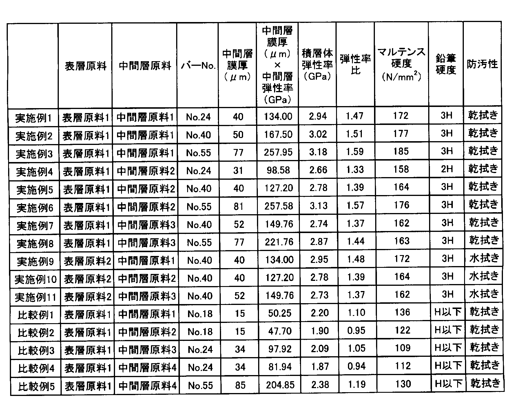
表2の結果から明らかなように、実施例1~8の積層体は鉛筆硬度試験で傷がつかず、また指紋汚れの乾拭き除去も可能で、防汚性と耐擦傷性とを両立していた。また、実施例9~11の積層体は指紋汚れを水拭き除去でき、乾拭きできる積層体と同様に適切な中間層が設けられていることで、基材に対しての傷付きを防ぐことができた。
一方、比較例1及び2の積層体は中間層が薄く、弾性率比が低いため、鉛筆硬度試験において基材に応力がかかり、圧痕が残った。比較例3~5の積層体は中間層が比較的柔らかく、中間層を厚く形成しても弾性率比が低く、基材への応力伝播が解消できないため、傷が付いた。
この出願は、2013年5月27日に出願された日本出願特願2013-110765を基礎とする優先権を主張し、その開示の全てをここに取り込む。
以上、実施形態及び実施例を参照して本願発明を説明したが、本願発明は上記実施形態及び実施例に限定されるものではない。本願発明の構成や詳細には、本願発明のスコープ内で当業者が理解し得る様々な変更をすることができる。
本発明に係る積層体は、微細凹凸構造を表面に有しても優れた耐擦傷性及び防汚性を示し、壁、屋根などの建材用途、家屋、自動車、電車、船舶などの窓材や鏡、人が手で触れうるディスプレイなどに利用可能であり、工業的に有用である。
10 積層体
11 基材
12 表層
13 凸部
13a 凸部の頂点
14 凹部
14a 凹部の底点
15 中間層
W1 隣り合う凸部の間隔
d1 凹部の底点から凸部の頂点までの垂直距離
11 基材
12 表層
13 凸部
13a 凸部の頂点
14 凹部
14a 凹部の底点
15 中間層
W1 隣り合う凸部の間隔
d1 凹部の底点から凸部の頂点までの垂直距離
Claims (19)
- 基材と、該基材上に積層された中間層と、該中間層上に積層された表層と、を含む積層体であって、該積層体に対して100mNでビッカース圧子を押し込んだ時の弾性率が、該基材単独に対して100mNでビッカース圧子を押し込んだ時の弾性率の1.30倍以上である積層体。
- 前記基材単独に対して100mNでビッカース圧子を押し込んだ時の弾性率が2.5GPa以下である請求項1記載の積層体。
- 前記中間層の厚みが20μm以上である請求項1記載の積層体。
- 前記中間層単独に対して100mNでビッカース圧子を押し込んだ時の弾性率が2.5GPa以上である請求項1記載の積層体。
- 前記中間層が下記式(1)の関係にある請求項1記載の積層体。
中間層の厚み(μm)×中間層単独の弾性率(GPa)≧98 (1) - 前記表層が、10mNでビッカース圧子を押し込んだ時の弾性率が800MPa以下の硬化樹脂を含む請求項1記載の積層体。
- 前記積層体に対して100mNでビッカース圧子を押し込んだ時のマルテンス硬度が140N/mm2以上である請求項1記載の積層体。
- 前記表層が微細凹凸構造を有する請求項1記載の積層体。
- 前記基材がポリカーボネートを含む請求項1記載の積層体。
- 請求項1~9の何れか一項記載の積層体を備えるディスプレイ。
- 請求項1~9の何れか一項記載の積層体を備える自動車用部材。
- 請求項1~9の何れか一項記載の積層体の製造方法であって、
基材上に中間層原料を供給し、活性エネルギー線照射によって前記中間層原料の膜を硬化させることで中間層を形成する工程と、
微細凹凸構造の反転構造を有するスタンパと、前記中間層との間に活性エネルギー線硬化性樹脂組成物を配置し、活性エネルギー線照射によって前記活性エネルギー線硬化性樹脂組成物を硬化させ、前記スタンパを剥離することにより、微細凹凸構造を有する表層を形成する工程と、を含む積層体の製造方法。 - 前記中間層を形成する工程において、酸素存在下での紫外線照射によって中間層原料の膜を完全な硬化には至らない状態まで硬化させる請求項12記載の積層体の製造方法。
- 請求項1~9の何れか一項記載の積層体の製造方法であって、
微細凹凸構造の反転構造を有するスタンパ上に活性エネルギー線硬化性樹脂組成物を塗布する工程と、
前記基材上に中間層原料を供給する工程と、
前記活性エネルギー線硬化性樹脂組成物が塗布されたスタンパを、活性エネルギー線硬化性樹脂組成物を塗布した面と、前記基材上に供給された中間層原料とが接するように被せる工程と、
活性エネルギー線照射によって前記活性エネルギー線硬化性樹脂組成物と前記中間層原料を同時に硬化させる工程と、
前記スタンパを剥離する工程と、を含む積層体の製造方法。 - 請求項1~9の何れか一項記載の積層体の製造方法であって、
微細凹凸構造の反転構造を有するスタンパ上に活性エネルギー線硬化性樹脂組成物を塗布し、活性エネルギー線照射によって前記活性エネルギー線硬化性樹脂組成物を硬化させる工程と、
前記基材上に中間層原料を供給する工程と、
前記硬化した活性エネルギー線硬化性樹脂組成物が存在するスタンパを、硬化した活性エネルギー線硬化性樹脂組成物が存在する面と、前記基材上に供給された中間層原料とが接するように被せる工程と、
活性エネルギー線照射によって前記中間層原料を硬化させる工程と、
前記スタンパを剥離する工程と、を含む積層体の製造方法。 - 前記活性エネルギー線硬化性樹脂組成物を硬化させる工程において、酸素存在下での活性エネルギー線照射によって、活性エネルギー線硬化性樹脂組成物の塗膜を完全な硬化には至らない状態まで硬化させる請求項15記載の積層体の製造方法。
- 前記中間層原料が、4官能以上の(メタ)アクリレートを50質量%以上含む請求項12記載の積層体の製造方法。
- 前記中間層原料を供給する際にエアナイフによって膜の厚さを制御する請求項12記載の積層体の製造方法。
- 前記中間層原料の供給をグラビアコーティング、バーコーティング、カーテンコーティング又はリバースコーティングにより行う請求項12記載の積層体の製造方法。
Priority Applications (1)
| Application Number | Priority Date | Filing Date | Title |
|---|---|---|---|
| JP2014527389A JPWO2014192709A1 (ja) | 2013-05-27 | 2014-05-27 | 積層体及びその製造方法 |
Applications Claiming Priority (2)
| Application Number | Priority Date | Filing Date | Title |
|---|---|---|---|
| JP2013110765 | 2013-05-27 | ||
| JP2013-110765 | 2013-05-27 |
Publications (1)
| Publication Number | Publication Date |
|---|---|
| WO2014192709A1 true WO2014192709A1 (ja) | 2014-12-04 |
Family
ID=51988738
Family Applications (1)
| Application Number | Title | Priority Date | Filing Date |
|---|---|---|---|
| PCT/JP2014/063899 Ceased WO2014192709A1 (ja) | 2013-05-27 | 2014-05-27 | 積層体及びその製造方法 |
Country Status (2)
| Country | Link |
|---|---|
| JP (1) | JPWO2014192709A1 (ja) |
| WO (1) | WO2014192709A1 (ja) |
Cited By (3)
| Publication number | Priority date | Publication date | Assignee | Title |
|---|---|---|---|---|
| JP2016165812A (ja) * | 2015-03-09 | 2016-09-15 | デクセリアルズ株式会社 | 防曇防汚積層体、及びその製造方法、物品、及びその製造方法、並びに防汚方法 |
| CN115151410A (zh) * | 2020-02-17 | 2022-10-04 | 三菱化学株式会社 | 层叠体和层叠体的制造方法 |
| JP2025096793A (ja) * | 2023-12-18 | 2025-06-30 | シャープディスプレイテクノロジー株式会社 | 抗菌性および/または抗ウイルス性を有する合成高分子膜を備える積層体、およびその製造方法 |
Citations (5)
| Publication number | Priority date | Publication date | Assignee | Title |
|---|---|---|---|---|
| JP2009031764A (ja) * | 2007-07-04 | 2009-02-12 | Mitsubishi Rayon Co Ltd | 反射防止物品、およびこれより得られる成形品、ならびにこれらを備えた自動車用部品 |
| JP2009230045A (ja) * | 2008-03-25 | 2009-10-08 | Dainippon Printing Co Ltd | 反射防止積層体 |
| JP2011000856A (ja) * | 2009-06-22 | 2011-01-06 | Dnp Fine Chemicals Co Ltd | 基材、中間膜及び微細凹凸構造膜を積層してなる積層体 |
| JP2012196965A (ja) * | 2011-03-10 | 2012-10-18 | Mitsubishi Rayon Co Ltd | 積層体及びその製造方法 |
| JP2013039711A (ja) * | 2011-08-15 | 2013-02-28 | Mitsubishi Rayon Co Ltd | 積層体 |
-
2014
- 2014-05-27 JP JP2014527389A patent/JPWO2014192709A1/ja active Pending
- 2014-05-27 WO PCT/JP2014/063899 patent/WO2014192709A1/ja not_active Ceased
Patent Citations (5)
| Publication number | Priority date | Publication date | Assignee | Title |
|---|---|---|---|---|
| JP2009031764A (ja) * | 2007-07-04 | 2009-02-12 | Mitsubishi Rayon Co Ltd | 反射防止物品、およびこれより得られる成形品、ならびにこれらを備えた自動車用部品 |
| JP2009230045A (ja) * | 2008-03-25 | 2009-10-08 | Dainippon Printing Co Ltd | 反射防止積層体 |
| JP2011000856A (ja) * | 2009-06-22 | 2011-01-06 | Dnp Fine Chemicals Co Ltd | 基材、中間膜及び微細凹凸構造膜を積層してなる積層体 |
| JP2012196965A (ja) * | 2011-03-10 | 2012-10-18 | Mitsubishi Rayon Co Ltd | 積層体及びその製造方法 |
| JP2013039711A (ja) * | 2011-08-15 | 2013-02-28 | Mitsubishi Rayon Co Ltd | 積層体 |
Cited By (6)
| Publication number | Priority date | Publication date | Assignee | Title |
|---|---|---|---|---|
| JP2016165812A (ja) * | 2015-03-09 | 2016-09-15 | デクセリアルズ株式会社 | 防曇防汚積層体、及びその製造方法、物品、及びその製造方法、並びに防汚方法 |
| CN107405861A (zh) * | 2015-03-09 | 2017-11-28 | 迪睿合株式会社 | 防雾防污层压体及其制造方法、物品及其制造方法、以及防污方法 |
| CN115151410A (zh) * | 2020-02-17 | 2022-10-04 | 三菱化学株式会社 | 层叠体和层叠体的制造方法 |
| EP4108445A4 (en) * | 2020-02-17 | 2024-03-20 | Mitsubishi Chemical Corporation | LAMINATE AND METHOD FOR MANUFACTURING LAMINATE |
| JP2025096793A (ja) * | 2023-12-18 | 2025-06-30 | シャープディスプレイテクノロジー株式会社 | 抗菌性および/または抗ウイルス性を有する合成高分子膜を備える積層体、およびその製造方法 |
| JP7853272B2 (ja) | 2023-12-18 | 2026-04-28 | シャープディスプレイテクノロジー株式会社 | 抗菌性および/または抗ウイルス性を有する合成高分子膜を備える積層体、およびその製造方法 |
Also Published As
| Publication number | Publication date |
|---|---|
| JPWO2014192709A1 (ja) | 2017-02-23 |
Similar Documents
| Publication | Publication Date | Title |
|---|---|---|
| JP5691951B2 (ja) | 積層体及びその製造方法 | |
| JP5260790B2 (ja) | 活性エネルギー線硬化性樹脂組成物、微細凹凸構造体及び微細凹凸構造体の製造方法 | |
| CN102883878B (zh) | 积层体及其制造方法 | |
| JP5162344B2 (ja) | 反射防止物品、およびこれを備えた自動車用部品 | |
| JP5648632B2 (ja) | 活性エネルギー線硬化性樹脂組成物、及びそれを用いたナノ凹凸構造体とその製造方法、及びナノ凹凸構造体を備えた撥水性物品 | |
| CN104349892B (zh) | 层积体 | |
| JP2008197217A (ja) | 成形体とその製造方法 | |
| JP6686284B2 (ja) | 活性エネルギー線硬化性樹脂組成物の硬化物を含む物品 | |
| JP2013029828A (ja) | 光透過性成形体及びそれを用いた反射防止物品 | |
| JP2009174007A (ja) | 鋳型とその製造方法、および成形体の製造方法 | |
| JP2009271782A (ja) | 導電性透明基材およびタッチパネル | |
| JP2012196965A (ja) | 積層体及びその製造方法 | |
| JP2013241503A (ja) | 多官能ウレタン(メタ)アクリレート、活性エネルギー線硬化性樹脂組成物及び微細凹凸構造を表面に有する物品 | |
| JP2012224709A (ja) | 活性エネルギー線硬化性樹脂組成物、及びそれを用いたナノ凹凸構造体と撥水性物品 | |
| JP5810591B2 (ja) | 積層体ならびに反射防止物品および撥水性物品 | |
| WO2014192709A1 (ja) | 積層体及びその製造方法 | |
| JP2009109572A (ja) | 反射防止物品 | |
| JP2014077040A (ja) | 活性エネルギー線硬化性組成物、およびそれを用いた微細凹凸構造体 | |
| JP2013222074A (ja) | 積層体の製造方法 | |
| JP2013190460A (ja) | 積層体及びその製造方法 | |
| WO2016006627A1 (ja) | 微細凹凸構造体 | |
| JP2015052724A (ja) | 微細凹凸フィルム |
Legal Events
| Date | Code | Title | Description |
|---|---|---|---|
| ENP | Entry into the national phase |
Ref document number: 2014527389 Country of ref document: JP Kind code of ref document: A |
|
| 121 | Ep: the epo has been informed by wipo that ep was designated in this application |
Ref document number: 14804481 Country of ref document: EP Kind code of ref document: A1 |
|
| NENP | Non-entry into the national phase |
Ref country code: DE |
|
| 122 | Ep: pct application non-entry in european phase |
Ref document number: 14804481 Country of ref document: EP Kind code of ref document: A1 |