WO2014192603A1 - Dispositif et procédé de sortie de signaux audio, dispositif et procédé de codage, dispositif et procédé de décodage, et programme - Google Patents
Dispositif et procédé de sortie de signaux audio, dispositif et procédé de codage, dispositif et procédé de décodage, et programme Download PDFInfo
- Publication number
- WO2014192603A1 WO2014192603A1 PCT/JP2014/063410 JP2014063410W WO2014192603A1 WO 2014192603 A1 WO2014192603 A1 WO 2014192603A1 JP 2014063410 W JP2014063410 W JP 2014063410W WO 2014192603 A1 WO2014192603 A1 WO 2014192603A1
- Authority
- WO
- WIPO (PCT)
- Prior art keywords
- audio signal
- gain
- reproduction
- speaker
- distance
- Prior art date
Links
Images


Classifications
-
- G—PHYSICS
- G10—MUSICAL INSTRUMENTS; ACOUSTICS
- G10L—SPEECH ANALYSIS OR SYNTHESIS; SPEECH RECOGNITION; SPEECH OR VOICE PROCESSING; SPEECH OR AUDIO CODING OR DECODING
- G10L19/00—Speech or audio signals analysis-synthesis techniques for redundancy reduction, e.g. in vocoders; Coding or decoding of speech or audio signals, using source filter models or psychoacoustic analysis
- G10L19/008—Multichannel audio signal coding or decoding using interchannel correlation to reduce redundancy, e.g. joint-stereo, intensity-coding or matrixing
-
- G—PHYSICS
- G10—MUSICAL INSTRUMENTS; ACOUSTICS
- G10L—SPEECH ANALYSIS OR SYNTHESIS; SPEECH RECOGNITION; SPEECH OR VOICE PROCESSING; SPEECH OR AUDIO CODING OR DECODING
- G10L21/00—Processing of the speech or voice signal to produce another audible or non-audible signal, e.g. visual or tactile, in order to modify its quality or its intelligibility
- G10L21/02—Speech enhancement, e.g. noise reduction or echo cancellation
- G10L21/0316—Speech enhancement, e.g. noise reduction or echo cancellation by changing the amplitude
- G10L21/0324—Details of processing therefor
- G10L21/034—Automatic adjustment
-
- H—ELECTRICITY
- H04—ELECTRIC COMMUNICATION TECHNIQUE
- H04S—STEREOPHONIC SYSTEMS
- H04S5/00—Pseudo-stereo systems, e.g. in which additional channel signals are derived from monophonic signals by means of phase shifting, time delay or reverberation
- H04S5/02—Pseudo-stereo systems, e.g. in which additional channel signals are derived from monophonic signals by means of phase shifting, time delay or reverberation of the pseudo four-channel type, e.g. in which rear channel signals are derived from two-channel stereo signals
-
- H—ELECTRICITY
- H04—ELECTRIC COMMUNICATION TECHNIQUE
- H04S—STEREOPHONIC SYSTEMS
- H04S7/00—Indicating arrangements; Control arrangements, e.g. balance control
- H04S7/30—Control circuits for electronic adaptation of the sound field
- H04S7/301—Automatic calibration of stereophonic sound system, e.g. with test microphone
-
- H—ELECTRICITY
- H04—ELECTRIC COMMUNICATION TECHNIQUE
- H04S—STEREOPHONIC SYSTEMS
- H04S7/00—Indicating arrangements; Control arrangements, e.g. balance control
- H04S7/30—Control circuits for electronic adaptation of the sound field
- H04S7/302—Electronic adaptation of stereophonic sound system to listener position or orientation
-
- H—ELECTRICITY
- H04—ELECTRIC COMMUNICATION TECHNIQUE
- H04S—STEREOPHONIC SYSTEMS
- H04S7/00—Indicating arrangements; Control arrangements, e.g. balance control
- H04S7/30—Control circuits for electronic adaptation of the sound field
- H04S7/308—Electronic adaptation dependent on speaker or headphone connection
-
- H—ELECTRICITY
- H04—ELECTRIC COMMUNICATION TECHNIQUE
- H04S—STEREOPHONIC SYSTEMS
- H04S5/00—Pseudo-stereo systems, e.g. in which additional channel signals are derived from monophonic signals by means of phase shifting, time delay or reverberation
- H04S5/005—Pseudo-stereo systems, e.g. in which additional channel signals are derived from monophonic signals by means of phase shifting, time delay or reverberation of the pseudo five- or more-channel type, e.g. virtual surround
Definitions
- the present technology relates to an audio signal output device and method, an encoding device and method, a decoding device and method, and a program, and in particular, an audio signal output device and method and code that can perform more realistic audio reproduction.
- the present invention relates to an encoding apparatus and method, a decoding apparatus and method, and a program.
- the speaker arrangement on the playback side be exactly the same as the position of the sound source, but in reality, the speaker position on the playback side and the position of the sound source are often different.
- VBAP Vector Base Amplitude Pannning
- the target sound image localization position is expressed as a linear sum of vectors pointing in the direction of two or three speakers around the localization position. Then, the coefficient multiplied by each vector in the linear sum is used as the gain of the audio signal output from each speaker, and gain adjustment is performed, so that the sound image is localized at the target position.
- the proposed reproduction method cannot reproduce or reproduce the sound.
- the sound quality and the definition of the sound image will be greatly degraded.
- the sound image definition is greatly degraded because the sound image of the channel-based sound source and the ideal speaker position where the sound source is played are almost always different. .
- This technology has been made in view of such a situation, and makes it possible to perform more realistic audio reproduction.
- the audio signal output device includes a distance calculation unit that calculates a distance between an ideal speaker position for reproducing an audio signal and an actual speaker position for reproducing the audio signal; A gain calculation unit that calculates a reproduction gain of the audio signal based on the distance; and a gain adjustment unit that adjusts the gain of the audio signal based on the reproduction gain.
- the gain calculation unit can calculate the reproduction gain based on curve information for obtaining the reproduction gain for each distance.
- the curve information can be information indicating a line curve or a function curve.
- the gain adjusting unit is based on the distance from the reference point to the ideal speaker and the radius of the unit circle. It is possible to further adjust the gain of the audio signal with a predetermined gain.
- the gain adjusting unit can delay the audio signal based on a delay time determined based on a distance from the reference point to the ideal speaker and a radius of the unit circle.
- the gain adjustment unit is determined based on a distance from the reference point to the actual speaker and a radius of the unit circle when the actual speaker is not on a unit circle centered on a predetermined reference point.
- the gain of the audio signal can be further adjusted by the gain.
- the gain adjusting unit can delay the audio signal based on a delay time determined based on a distance from the reference point to the actual speaker and a radius of the unit circle.
- the audio signal output device may further include a gain correction unit that corrects the reproduction gain based on a distance between an ideal center speaker position and the actual speaker position.
- the audio signal output device may further include a lower limit correction unit that corrects the reproduction gain when the reproduction gain is smaller than a predetermined lower limit.
- the audio signal output device includes an expected value of the sound pressure of the input sound based on the input audio signal, and the entire output sound based on the audio signal gain-adjusted by the reproduction gain based on the reproduction gain.
- An overall gain correction unit that calculates a ratio between the power and the overall power of the input sound and corrects the reproduction gain based on the ratio can be further provided.
- the audio signal output method or program calculates a distance between an ideal speaker position for reproducing an audio signal and an actual speaker position for reproducing the audio signal, and calculates the distance. And calculating a reproduction gain of the audio signal based on the reproduction gain and adjusting the gain of the audio signal based on the reproduction gain.
- a distance between an ideal speaker position for reproducing an audio signal and an actual speaker position for reproducing the audio signal is calculated, and the audio signal is reproduced based on the distance.
- a reproduction gain is calculated, and gain adjustment of the audio signal is performed based on the reproduction gain.
- the encoding device corrects the gain of the audio signal according to the distance between the ideal speaker position for reproducing the audio signal and the actual speaker position for reproducing the audio signal.
- a correction information generation unit that generates correction information for performing the correction, an encoding unit that encodes the audio signal, and an output unit that outputs a bit stream including the correction information and the encoded audio signal.
- the encoding method corrects the gain of the audio signal according to the distance between the ideal speaker position for reproducing the audio signal and the actual speaker position for reproducing the audio signal. Generating correction information for encoding, encoding the audio signal, and outputting a bitstream including the correction information and the encoded audio signal.
- the gain of the audio signal is corrected according to the distance between the ideal speaker position for reproducing the audio signal and the actual speaker position for reproducing the audio signal. Correction information is generated, the audio signal is encoded, and a bit stream including the correction information and the encoded audio signal is output.
- the decoding device corrects the gain of the audio signal according to the distance between the ideal speaker position for reproducing the audio signal and the actual speaker position for reproducing the audio signal. Correction information, an extraction unit that extracts the encoded audio signal from a bitstream, a decoding unit that decodes the encoded audio signal, and outputs the decoded audio signal and the correction information And an output unit.
- the correction information can be the ideal speaker position information.
- the correction information can be curve information for obtaining a gain for each of the distances.
- the curve information can be information indicating a line curve or a function curve.
- the decoding method corrects the gain of the audio signal according to the distance between the ideal speaker position for reproducing the audio signal and the actual speaker position for reproducing the audio signal. And extracting the encoded audio signal from the bitstream, decoding the encoded audio signal, and outputting the decoded audio signal and the correction information.
- the gain of the audio signal is corrected according to the distance between the ideal speaker position for reproducing the audio signal and the actual speaker position for reproducing the audio signal.
- the correction information and the encoded audio signal are extracted from the bitstream, the encoded audio signal is decoded, and the decoded audio signal and the correction information are output.
- the present technology relates to a reproduction method for reproducing a sound source of an arbitrary channel with an arbitrary number of speakers, and an encoding (decoding) technique of information (metadata) necessary for realizing the reproduction method.
- audio signals of a plurality of channels and metadata of these audio signals are supplied to the playback device, and the playback device controls the playback of audio based on the metadata and the audio signal.
- the audio signal of each channel is a signal generated as reproduced by a speaker arranged at an ideal position indicated by the metadata.
- a virtual speaker that reproduces an audio signal of each channel at a position indicated by metadata is referred to as an ideal speaker.
- an actual speaker that outputs sound based on the audio signal output from the playback device is referred to as a playback speaker.
- the audio signals of all channels are classified into audio signals for LFE (Low Frequency Effect) and audio signals that are not for LFE.
- LFE Low Frequency Effect
- all ideal speakers are classified into LFE speakers and non-LFE speakers.
- playback speakers are also classified into LFE speakers and non-LFE speakers.
- the gain of the audio signal is adjusted based on the distance between the ideal speaker and the reproduction speaker.
- the ideal speaker VSP1 on the surface of the radius r u sphere PH11 around the position of the user U11 is viewer is located and reproduction speaker RSP11-1 to reproduction speaker RSP11-3.
- the ideal speaker VSP1 and the reproduction speakers RSP11-1 to RSP11-3 are speakers that are not for LFE.
- the reproduction speaker RSP11-1 to the reproduction speaker RSP11-3 are also simply referred to as the reproduction speaker RSP11 when it is not necessary to distinguish them. Further, in this example, only one ideal speaker and three reproduction speakers are shown in the figure, but there are actually other ideal speakers and reproduction speakers.
- the sound based on the audio signal of the channel corresponding to the ideal speaker VSP1 is localized at the position of the ideal speaker VSP1.
- the reproduction gain of each reproduction speaker RSP11 is determined according to the distance between the ideal speaker VSP1 and the reproduction speaker RSP11, and the sound based on the audio signal is output from each reproduction speaker RSP11 with the reproduction gain.
- a sound image is localized at the position of the ideal speaker VSP1.
- the distance between the ideal speaker VSP1 and the reproduction speaker RSP11 is an angle formed by a vector starting from the user U11 and pointing toward the ideal speaker VSP1 and a vector starting from the user U11 and pointing toward the reproduction speaker RSP11.
- the distance between the ideal speaker VSP1 and the reproduction speaker RSP11 is the distance between the ideal speaker VSP1 and the reproduction speaker RSP11 on the surface of the sphere PH11, that is, the length of the arc connecting the two speakers.
- the angle formed by the arrow A11 and the arrow A12 is the distance DistM1 between the ideal speaker VSP1 and the reproduction speaker RSP11-1.
- an angle formed by the arrow A11 and the arrow A13 is a distance DistM2 between the ideal speaker VSP1 and the reproduction speaker RSP11-2
- an angle formed by the arrow A11 and the arrow A14 is an ideal speaker VSP1 and the reproduction speaker RSP11-3. Distance with DistM3.
- the audio signal of the channel of the ideal speaker VSP1 is reproduced by the reproduction speaker RSP11-1 after gain adjustment based on the distance DistM1.
- the audio signal of the channel of the ideal speaker VSP1 is gain-adjusted based on the distance DistM2 and the distance DistM3, respectively, and is reproduced by the reproduction speaker RSP11-2 and the reproduction speaker RSP11-3.
- M ideal speakers that are not for LFE that is, M-channel audio signals are downmixed into N-channel audio signals, and these N-channel audio signals are reproduced for N non-LFE signals.
- An example of reproduction by a speaker will be described.
- ⁇ About processing STE1> First, in the processing STE1, the distance between the speakers is obtained.
- the positions of the speakers are the horizontal angle ⁇ ( ⁇ 180 ° ⁇ ⁇ ⁇ + 180 °) and the vertical angle ⁇ ( ⁇ 90 ° ⁇ ⁇ ⁇ + 90). °) and the distance r (0 ⁇ r ⁇ + ⁇ ) from the user to the speaker.
- a plane including a straight line in the depth direction in the figure and a straight line in the horizontal direction in the figure is an xy plane
- a straight line in a reference direction in the xy plane, for example, the y axis, and the user U11 is the starting point.
- the angle formed by the speaker direction vector on the xy plane is the horizontal direction angle ⁇ . That is, the horizontal direction angle ⁇ is an angle in the horizontal direction in FIG.
- the angle formed between the speaker direction vector starting from the user U11 and the xy plane is the vertical angle ⁇
- the length of the straight line connecting the user U11 and the speaker is the distance r.
- the horizontal angle ⁇ , the vertical angle ⁇ , and the distance r indicating the position of each ideal speaker are supplied to the playback device as metadata of the audio signal.
- the playback device is also supplied with a horizontal angle ⁇ , a vertical angle ⁇ , and a distance r indicating the position of each playback speaker.
- the horizontal direction angle ⁇ , the vertical direction angle ⁇ , and the distance r of the mth ideal speaker among the M ideal speakers are represented by ⁇ im , ⁇ im , and r im , respectively.
- the horizontal direction angle ⁇ , the vertical direction angle ⁇ , and the distance r of the nth playback speaker among the N playback speakers are represented by ⁇ on , ⁇ on , and r on , respectively.
- the distance Dist (m, n) between the mth ideal speaker and the nth playback speaker is obtained by the following equation (1).
- the ideal speaker and reproducing speaker on the unit circle of radius r u i.e. if it is placed on a sphere PH11 shown in FIG. 1, the audio output from the speakers reaches the user U11 simultaneously.
- the sound from the speakers will not only reach the user U11 earlier or later than the sound from other speakers, but will also be heard by the user. The sound pressure of the voice will also change.
- the reproducing apparatus with respect to the distance r im ⁇ r u audio signal of the ideal speaker is, the correction of the sound pressure is performed by the correction value SoundPressureCorrection im, delay processing is performed by the delay time Delay im.
- the correction value SoundPressureCorrection im obtained by the equation (2) is used for correcting the audio signal of the channel m input to the ideal speaker side, that is, the reproduction apparatus.
- an audio signal input to the playback device is also referred to as an input audio signal
- an audio signal output from the playback device is also referred to as an output audio signal.
- the delay time Delay im for delay processing to the input audio signal of the ideal speaker is calculated by the following equation (3) based on the distance r im and the radius r u.
- r im> delay Delay im in the case of r u is a negative value, the audio signal is delay processing is delayed in the negative direction, that is that the audio signal is shifted in the direction of the front temporally become.
- the correction value SoundPressureCorrection on is calculated by the following equation (4), and the delay time Delay on is calculated by the equation (5).
- the correction value SoundPressureCorrection on and the delay time Delay on thus obtained are the sound pressure correction value and the delay time for the reproduction speaker side, that is, the output audio signal.
- the correction of the sound pressure is performed by the correction value SoundPressureCorrection on
- delay processing is performed by the delay time Delay on.
- each of the M ideal speakers it is specified whether or not there is a playback speaker whose distance Dist (m, n) to the ideal speaker is “0”, and each ideal speaker is at the playback speaker position. It is classified as either a speaker or a speaker that is not at the playback speaker position.
- the reproduction gain MixGain (m, n) of the nth reproduction speaker for the audio signal of the channel m corresponding to the mth ideal speaker is It is calculated by the following equation (6).
- the reproduction gain MixGain (m, n) of the reproduction speaker whose distance Dist (m, n) is “0”, that is, the reproduction speaker at the same position as the m-th ideal speaker is 0 dB.
- the reproduction gain MixGain (m, n) of a reproduction speaker whose distance Dist (m, n) is not “0”, that is, a reproduction speaker at a position different from the mth ideal speaker is set to ⁇ dB.
- the audio signal of the channel m corresponding to the mth ideal speaker is reproduced on the reproduction speaker at the same position as the ideal speaker. That is, the audio component of channel m is not output from other playback speakers.
- the metadata supplied to the playback device includes curve information indicating which playback gain is to be obtained using a curved line curve or a function curve, and the playback device includes the metadata.
- the reproduction gain is calculated using the type of curve shown in the included curve information.
- the metadata includes a curve index indicating which curve is specifically used among the types of curves shown in the curve information.
- the curve index may be information indicating a new curve that is not recorded in the playback device.
- the playback device calculates playback gain using information recorded in advance for obtaining a curve such as a coefficient.
- the curve index is information indicating a new curve
- the playback device reads information for obtaining a new curve from the metadata, and calculates a playback gain using the curve obtained from the information. .
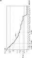
- a polygonal curve used for calculation of the reproduction gain is expressed by a numerical sequence composed of reproduction gain values for each distance Dist (m, n).
- the value of the kth point in the sequence is the reproduction gain when the distance Dist (m, n) shown in the following equation (7).
- the reproduction gain changes linearly according to the distance Dist (m, n) between adjacent points in the sequence.
- the polygonal line curve obtained by such a sequence is a curve representing the mapping between the reproduction gain MixGain (m, n) and the distance Dist (m, n).
- the vertical axis represents the value of the reproduction gain
- the horizontal axis represents the distance between the ideal speaker and the reproduction speaker.
- a polygonal line CV11 represents a polygonal line curve
- a square on the polygonal line curve represents one numerical value constituting a numerical sequence of reproduction gain values.
- the playback gain MixGain (m, n) of the nth playback speaker is a broken line.
- the gain value at DistM1 on the curve is -3.5dB.
- the reproduction gain MixGain (m, n) of the reproduction speaker whose distance Dist (m, n) is DistM2 is set to -8 dB which is the gain value in DistM2 on the polygonal curve, and the distance Dist (m, n) is
- the reproduction gain MixGain (m, n) of the reproduction speaker which is DistM3 is set to -16.5 dB which is a gain value in DistM3 on the polygonal curve.
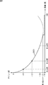
- the function curve used for calculating the reproduction gain is represented by three coefficients coef1, coef2, and coef3, and a gain value MinGain that is a predetermined lower limit.
- the reproducing apparatus uses a function f (Dist (m, n)) expressed by the following equation (8) expressed by the coefficients coef1 to coef3, the gain value MinGain, and the distance Dist (m, n):
- the following equation (9) is calculated, and the reproduction gain MixGain (m, n) of each reproduction speaker for the mth ideal speaker is calculated.
- Cut_thre is the minimum value that satisfies the following Expression (10).
- the function curve represented by such a function f (Dist (m, n)) or the like is, for example, the curve shown in FIG. In FIG. 3, the vertical axis represents the value of the reproduction gain, and the horizontal axis represents the distance between the ideal speaker and the reproduction speaker.
- a curve CV21 represents a function curve.
- the reproduction gain MixGain (m, n) of the nth reproduction speaker is a function.
- the gain value at DistM1 on the curve is -6dB.
- the reproduction gain MixGain (m, n) of the reproduction speaker whose distance Dist (m, n) is DistM2 is set to -12 dB which is the gain value in DistM2 on the function curve, and the distance Dist (m, n) is The reproduction gain MixGain (m, n) of the reproduction speaker which is DistM3 is set to -18 dB which is a gain value in DistM3 on the function curve.
- the combinations [coef1, coef2, coef3] of the coefficients coef1 to coef3 are, for example, [8, -12,6] and [1, -3, 3], [2, -5.3, 4.2].
- the reproduction gain MixGain (m, n) of each of the N reproduction speakers is obtained for each of the M ideal speakers.
- the reproduction gain values of these reproduction speakers become larger as the distance Dist (m, n) from the ideal speaker is shorter, and the volume of the sound becomes larger.
- the reproduction gain MixGain (m, n) is a mix gain when M> N.
- the reproduction gain of each reproduction speaker is corrected depending on where each of the N reproduction speakers is located, for example, forward or backward with respect to the user, and the sound output by the position of the reproduction speaker is uncomfortable. Not to be made. That is, when the audio signal of the ideal speaker is reproduced by two reproduction speakers at the front and the rear of the user having the same distance Dist (m, n) from the ideal speaker, the reproduction speaker at the rear of the user The reproduction gain is corrected so as to be smaller than the reproduction gain of the front reproduction speaker.
- the playback apparatus acquires information indicating whether or not the correction of the playback gain according to the position of the playback speaker is necessary from the metadata, and the acquired information does not require the correction of the playback gain. If the information is to that effect, the process STE3 is not performed. That is, after the process STE2, the process STE3 is skipped and the process STE4 is performed.
- the reproduction device performs the same calculation as in Expression (1), and each of the N reproduction speakers, A distance Dist (n, C) from the space origin C is obtained.
- the space origin C is a reference position on the space where the reproduction speaker is arranged.
- the position of the space origin C is on the unit circle, that is, the sphere PH11 of FIG. 1, and is located in front of the user U11.
- Such a position of the space origin C is an ideal position of the center speaker.
- the correction coefficient spkr_pos_correction_coeffcient (n) for each of the N reproduction speakers is obtained by the calculation of the following equation (11).
- Max_spkr_pos_correction_coeffcient indicates a correction coefficient when the distance Dist (n, C) is maximum (180 °).
- MaxMixGain (n) is the maximum value of M reproduction gains for the nth reproduction speaker, that is, the reproduction gain MixGain (m, n) having the same value of n.
- a term including MaxMixGain (n) is a term of inverse correction for preventing correction by spkr_pos_correction_coeffcient (n) from being performed excessively.
- the reproduction gain MixGain (m, n) is directly used as the reproduction gain MixGain_pos_corr (m, n).
- the maximum value MaxMixGain i (m) of the N reproduction gains MixGain_pos_corr (m, n) having the same m value is obtained for each ideal speaker obtained in the processing STE3, and the maximum value MaxMixGain i (m) is compared with the lower limit value MixGain MinThre .
- the N reproduction gains MixGain_pos_corr (m, n) for the mth ideal speaker are:
- the correction value MinGain correctioni (m) is added.
- the correction value MinGain correctioni (m) is a difference between the maximum value MaxMixGain i (m) and the lower limit value MixGain MinThre as shown in the following equation (13).
- the playback device reads the expected value SPR_i (m) of the relative sound pressure between each channel of the ideal speaker from the metadata, and assumes that the absolute sound pressure of the ideal speaker with the highest sound pressure is 0 dBFS.
- the sound pressure of the sound of the audio signal of each channel is calculated from each expected value SPR_i (m) for each speaker, and the power value pow_i of the entire sound of the input audio signal is obtained.
- the power value pow_i is the total power of the sound (hereinafter also referred to as input sound) output from the ideal speaker by reproducing the audio signals of each of the M channels.
- the sound output from the reproduction speaker by reproducing the audio signals of the N channels is also referred to as output sound.
- the playback device multiplies the playback gain MixGain_pos_corr (m, n) obtained in the process STE4 by the expected value SPR_i (m), so that the expected value SPR_o ( n) is obtained, and the power value pow_o of the entire output speech is obtained from the expected value SPR_o (n).
- the playback device multiplies all playback gains MixGain_pos_corr (m, n) obtained in process STE4 by the ratio (pow_o / pow_i) of the power values of the input sound and the output sound to correct the sound pressure of the entire output sound. To do.
- the reproduction gain obtained in this way becomes the final reproduction gain of each reproduction speaker for each ideal speaker.
- the absolute sound pressure of the ideal speaker with the highest sound pressure was assumed to be 0 dB, and the ratio of the power values of the input sound and output sound (pow_o / pow_i) was calculated.
- the value is the actual absolute sound pressure. It becomes the same value as the ratio (pow_o / pow_i) of the power value of the input voice and the output voice obtained using.
- the ratio (pow_o / pow_i) of the power value of the input sound and the output sound can be obtained even if the absolute sound pressure of the actual input sound is not known. .
- the ratio of the resulting power values is the same value.
- the number of ideal speakers for LFE is either 0, 1 or 2, and similarly, the number of playback speakers for LFE is 0, 1 or 2. It becomes.
- the playback device when the number of ideal speakers or playback speakers for LFE is one or two, the playback device generates an audio signal for each channel for LFE using, for example, the playback gain shown in FIG. The
- the audio signal of the LFE ideal speaker is reproduced as it is as the audio signal of the LFE playback speaker.
- the audio signal of the ideal speaker is gain-adjusted with the same playback gain and is played back by two playback speakers. If there is one LFE playback speaker for two LFE ideal speakers, the audio signals of the ideal speakers are added together with the same playback gain to form one audio signal, which is played back by the playback speaker.
- the playback device is configured as shown in FIG. 5, for example.
- FIG. 5 only functional blocks for reproducing audio signals of channels not for LFE in the reproduction apparatus 11 are shown, and functional blocks for reproducing audio signals of channels for LFE are not shown. Has been.
- each speaker 12 is a speaker corresponding to the reproduction speaker RSP11 described above, the speaker 12 is also referred to as a reproduction speaker 12.
- the gain adjustment unit 26 includes an amplification unit 31, an amplification unit 32, and an amplification unit 33.
- the distance calculation unit 21 is supplied with the position information of each ideal speaker that is not for LFE and the position information of each reproduction speaker 12 included in the metadata.
- the distance calculation unit 21 calculates a distance Dist (m, n) based on the position information of the ideal speaker and the position information of the reproduction speaker 12 and supplies the distance Dist (m, n) to the reproduction gain calculation unit 22.
- the position information of each speaker is information including a horizontal angle ⁇ , a vertical angle ⁇ , and a distance r.
- the distance calculation unit 21 calculates the correction value SoundPressureCorrection im and delay time Delay im on the ideal speaker as needed and supplies them to the amplification unit 31, and also corrects the correction value SoundPressureCorrection on and delay time Delay on the reproduction speaker 12 side. on is calculated and supplied to the amplifying unit 33. That is, the distance calculation unit 21 performs the process STE1.
- the reproduction gain calculation unit 22 is supplied with the curve information and the curve index included in the metadata, and the reproduction gain calculation unit 22 uses the curve information and the curve index and the distance supplied from the distance calculation unit 21.
- the reproduction gain MixGain (m, n) is calculated and supplied to the correction unit 23. That is, the reproduction gain calculation unit 22 performs the process STE2.
- the correction unit 23 includes position information of the reproduction speaker 12, information indicating whether or not reproduction gain correction according to the arrangement position of the reproduction speaker 12 is necessary, and a correction coefficient Max_spkr_pos_correction_coeffcient included in the metadata. Supplied.
- the correction unit 23 Based on the supplied information, the correction unit 23 corrects the reproduction gain supplied from the reproduction gain calculation unit 22 according to the arrangement position of the reproduction speaker 12, and the reproduction gain MixGain_pos_corr obtained as a result thereof. (m, n) is supplied to the lower limit correction unit 24. In other words, the correction unit 23 performs the process STE3.
- the lower limit correction unit 24 is supplied with the lower limit value MixGain MinThre of the reproduction gain included in the metadata.
- the lower limit correction unit 24 corrects the reproduction gain supplied from the correction unit 23 based on the lower limit MixGain MinThre , and supplies the correction to the overall gain correction unit 25. That is, the lower limit correction unit 24 performs the process STE4.
- the expected value SPR_i (m) of the relative sound pressure between the channels of the ideal speaker included in the metadata is supplied to the overall gain correction unit 25.
- the overall gain correction unit 25 corrects the reproduction gain supplied from the lower limit correction unit 24 based on the expected value SPR_i (m), and supplies the final reproduction gain obtained as a result to the amplification unit 32. .
- the process STE5 is performed.
- the gain adjusting unit 26 performs gain adjustment on the audio signals of M ideal speakers supplied from a decoder (not shown) to generate an N-channel audio signal, and supplies the audio signal of each channel to the reproduction speaker 12. To play the sound. In the gain adjustment unit 26, the process STE6 is performed.
- the amplifying unit 31 appropriately performs gain correction and delay processing on the supplied M-channel audio signal based on the correction value and the delay time supplied from the distance calculating unit 21 to the amplifying unit 32. Supply.
- the amplification unit 32 multiplies the M channel audio signal supplied from the amplification unit 31 by the reproduction gain supplied from the overall gain correction unit 25.
- the amplifying unit 32 generates an N-channel audio signal by adding the audio signals of the respective ideal speakers multiplied by the reproduction gain, and supplies the N-channel audio signal to the amplifying unit 33.
- the amplification unit 33 Based on the correction value and delay time supplied from the distance calculation unit 21, the amplification unit 33 appropriately performs gain correction and delay processing on the N-channel audio signal supplied from the amplification unit 32, and reproduces the speaker. 12 is supplied.
- the playback device 11 supplies the audio signal supplied to the playback speaker for the audio signal for LFE and the audio signal not for LFE, respectively. Generate and output.
- step S ⁇ b> 11 the distance calculation unit 21 determines the distance Dist () between the ideal speaker and the reproduction speaker 12 based on the position information of the ideal speaker that is not for LFE and the position information of the reproduction speaker 12 that is not for LFE included in the metadata.
- m, n) is obtained and supplied to the reproduction gain calculator 22.
- the calculation of Expression (1) is performed for each combination of the ideal speaker and the reproduction speaker 12, and M ⁇ N distances Dist (m, n) are obtained.
- step S12 the distance calculation unit 21 obtains correction values and delay times on the ideal speaker side and the reproduction speaker 12 side as necessary.
- the ideal speaker is the distance r im ⁇ r u
- the value SoundPressureCorrection im and the delay time Delay im are calculated and supplied to the amplifying unit 31.
- the distance calculation unit 21 calculates Equation (4) and Equation (5) based on the distance r on as the position information of the reproduction speaker 12 for the reproduction speaker with the distance r on ⁇ r u , and the correction value SoundPressureCorrection on and delay time Delay on are calculated and supplied to the amplifying unit 33.
- step S13 the reproduction gain calculation unit 22 obtains the reproduction gain of each reproduction speaker 12 for each ideal speaker based on the distance Dist (m, n) supplied from the distance calculation unit 21.
- the reproduction gain calculation unit 22 calculates Equation (6) for an ideal speaker in which there is the reproduction speaker 12 in which the distance Dist (m, n) between the ideal speaker and the reproduction speaker 12 is “0”. Then, the reproduction gain MixGain (m, n) of each reproduction speaker 12 for the ideal speaker is calculated.
- the reproduction gain calculation unit 22 refers to the curve index and reads a polygonal curve or a function curve from the metadata as necessary.
- the reproduction gain calculation unit 22 obtains a gain value corresponding to the distance Dist (m, n) based on the obtained curve, and uses the obtained gain value as the reproduction speaker 12 of the ideal speaker. A reproduction gain MixGain (m, n) for. At this time, calculation of Expression (7) and Expression (9) is performed as necessary.
- the reproduction gain calculation unit 22 supplies the reproduction gain MixGain (m, n) to the correction unit 23.
- step S14 the correction unit 23 reproduces the reproduction gain supplied from the reproduction gain calculation unit 22 as necessary based on information indicating whether or not the reproduction gain included in the metadata is necessary. 12 is corrected according to the arrangement position and supplied to the lower limit correction unit 24.
- the correction unit 23 uses the position information of each reproduction speaker 12 and the correction coefficient Max_spkr_pos_correction_coeffcient included in the metadata to calculate Expression (11) and Expression (12), thereby reproducing The gain MixGain_pos_corr (m, n) is calculated.
- step S ⁇ b> 15 the lower limit correction unit 24 corrects the reproduction gain supplied from the correction unit 23 based on the lower limit value MixGain MinThre included in the metadata, and supplies it to the overall gain correction unit 25 as necessary. To do. Specifically, Expression (13) is calculated as necessary, and the correction value MinGain correctioni (m) is added to the reproduction gain MixGain_pos_corr (m, n).
- step S16 the overall gain correction unit 25 corrects the sound pressure of the entire output sound.
- the overall gain correction unit 25 inputs and outputs the input sound based on the expected value SPR_i (m) included in the metadata and the reproduction gain MixGain_pos_corr (m, n) supplied from the lower limit correction unit 24.
- the ratio (pow_o / pow_i) of the overall power value of the sound is calculated.
- the overall gain correction unit 25 multiplies the reproduction gain MixGain_pos_corr (m, n) by the power value ratio (pow_o / pow_i) to obtain a final reproduction gain, which is supplied to the amplification unit 32.
- step S17 the amplification unit 31 adjusts the gain of the audio signal based on the correction value and delay value on the ideal speaker side supplied from the distance calculation unit 21.
- the amplifying unit 31 multiplies the audio signal by the correction value SoundPressureCorrection im for the audio signal of the channel m to which the correction value and the delay value are supplied, and the resulting audio signal is timed by the delay time Delay im.
- the signal is delayed in the direction and supplied to the amplifying unit 32.
- step S ⁇ b> 18 the amplification unit 32 generates an audio signal of each reproduction speaker 12 based on the reproduction gain supplied from the overall gain correction unit 25 and the audio signal supplied from the amplification unit 31, and the amplification unit 33. To supply.
- the amplifying unit 32 sets the reproduction gain of each ideal speaker for the channel of attention nc to the ideal speaker. Multiply the audio signal. Then, the amplifying unit 32 sets the audio signal of each ideal speaker multiplied by the reproduction gain, that is, one audio signal obtained by adding the M audio signals, as the audio signal of the channel of interest nc. By performing the same processing using each of the N channels as the channel of interest, the audio signals of the M ideal speakers are converted into the audio signals of the N playback speakers 12.
- step S19 the amplifying unit 33 adjusts the gain of the audio signal supplied from the amplifying unit 32 based on the correction value and delay value on the reproduction speaker 12 side supplied from the distance calculating unit 21.
- the amplifying unit 33 multiplies the audio signal by the correction value SoundPressureCorrection on the audio signal of the channel n to which the correction value and the delay value are supplied, and the resulting audio signal is delayed by the delay time Delay on. The signal is delayed in the direction and supplied to the reproduction speaker 12.
- the reproduction speaker 12 reproduces sound based on the audio signal supplied from the reproduction device 11.
- the playback device 11 performs gain adjustment (gain correction) of the audio signal according to the distance between the position of the ideal speaker and the actual position of the playback speaker 12. Thereby, even when there is a difference between the positions of the ideal speaker and the reproduction speaker 12, it is possible to suppress the deterioration of the sound quality of the output sound and the definition of the sound image, and more realistic audio reproduction can be performed. .
- the input audio signals of any one or more channels can be reproduced by the reproduction speakers arranged at any one or more arbitrary positions. Further, even when the input audio signal of each channel is an audio signal having each object as a sound source, audio reproduction at a correct sound image position can be performed by the same downmix processing.
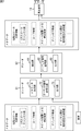
- Metadata is supplied from the encoder 61 to the decoder 62, and further metadata is supplied from the decoder 62 to the playback device 11.
- the encoder 61 obtains information necessary for obtaining metadata from the outside and the audio signals of each of the M ideal speakers, and generates a bit stream composed of the encoded metadata and the audio signal.
- the encoder 61 includes a metadata generation unit 71, an audio signal encoding unit 72, and an output unit 73.
- the metadata generation unit 71 acquires necessary information from the outside, encodes the acquired information as necessary, and generates encoded metadata.
- the metadata includes position information of each ideal speaker, the number of ideal speakers for LFE (number of channels) among the ideal speakers, curve information, and a curve index. Further, the metadata includes information indicating whether or not reproduction gain correction according to the arrangement position of the reproduction speaker 12 is necessary, a correction coefficient Max_spkr_pos_correction_coeffcient depending on the arrangement of the reproduction speaker 12, a lower limit value MixGain MinThre of the gain, and between channels The expected relative sound pressure value SPR_i (m) is also included.
- the audio signal encoding unit 72 encodes an audio signal supplied from the outside.
- the output unit 73 generates a bit stream including the encoded metadata and the encoded audio signal, and outputs the bit stream to the decoder 62.
- the decoder 62 includes an extraction unit 81, an audio signal decoding unit 82, and an output unit 83.
- the decoder 62 receives the bit stream transmitted from the encoder 61, and the extraction unit 81 extracts metadata and an audio signal from the received bit stream. At this time, the extraction unit 81 decodes the metadata as necessary.
- the audio signal decoding unit 82 decodes the audio signal extracted by the extraction unit 81.
- the output unit 83 supplies the metadata extracted by the extraction unit 81 and the audio signal decoded by the audio signal decoding unit 82 to the playback device 11.
- FIG. 8 shows a syntax of part of the metadata.
- “down mix coef exist ⁇ flag ” is arranged at the head of the header as information indicating whether or not information necessary for downmixing is included in the metadata.
- Polyline curve idx indicates a line curve, and when this value is a binary number “111”, it indicates a new line curve.
- polyline curve coeffcient [j] is described as information for obtaining a new polygonal curve.
- the information for obtaining a new broken line curve is, for example, information for specifying each point of a square (hereinafter referred to as a description point) on the broken line CV11 shown in FIG.
- the reproduction gain axis (vertical axis) is divided into 16 parts
- 16 dividing lines are defined. Each description point is sequentially arranged on each dividing line on the vertical axis.
- description points are represented by “0”, and information indicating on which dividing line each description point is arranged is represented by “1”.
- description points are described in order from the left.
- information indicating the number of dividing lines from the top where the first description point is from the top is described by the number “1”.
- “0” representing the description point is described.
- the first description point from the left is located on the highest division line, only “0” representing the description point is described.
- function curve idx indicates a function curve, and when this value is “111” in binary, it indicates that this is a new function curve.
- function_curve_coeffcient [i] is described as the coefficient of the new function curve.
- “minimun_gain_threshold_idx” described in the metadata is an index indicating a lower limit value MixGain MinThre of gain.
- “gain_correction_coeffcient” described in the metadata is a correction coefficient Max_spkr_pos_correction_coeffcient necessary for correcting the reproduction gain in accordance with the arrangement position of the reproduction speaker 12.
- Max_spkr_pos_correction_coeffcient is “1”, it means that the correction of the reproduction gain according to the arrangement position of the reproduction speaker 12 is not necessary.
- “sound_level_exist_flag” which is information indicating whether or not the expected value SPR_i (m) of relative sound pressure between channels is described in the metadata is described. “Channel sound level [i]” is described according to the value. “Channel sound level [i]” is the expected value SPR_i (m).
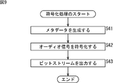
- step S41 the metadata generation unit 71 acquires necessary information from the outside and encodes the acquired information to generate encoded metadata.
- the metadata generation unit 71 generates metadata corresponding to the syntax shown in FIG.
- step S42 the audio signal encoding unit 72 encodes the audio signal supplied from the outside.
- step S43 the output unit 73 generates a bit stream including the encoded metadata and the encoded audio signal, and outputs the bit stream to the decoder 62.
- the bit stream is output, the encoding process ends.
- the encoder 61 generates and outputs metadata including ideal speaker position information, curve information, and the like.
- the reproduction apparatus 11 performs gain correction in accordance with the distance between the ideal speaker position and the actual reproduction speaker 12 position.
- gain correction can be performed.
- more realistic audio reproduction can be performed.
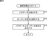
- step S71 the decoder 62 receives the bit stream transmitted from the encoder 61, and the extraction unit 81 extracts metadata and an audio signal from the received bit stream.
- the extraction unit 81 also performs metadata decoding.
- step S72 the audio signal decoding unit 82 decodes the audio signal extracted by the extraction unit 81.
- step S73 the output unit 83 outputs the decoded metadata and the decoded audio signal to the playback device 11, and the decoding process ends.
- the decoder 62 decodes the metadata and the audio signal, and outputs the metadata and the audio signal including the position information of the ideal speaker, the curve information, and the like to the playback device 11.
- the reproduction apparatus 11 performs gain correction in accordance with the distance between the ideal speaker position and the actual position of the reproduction speaker 12.
- gain correction can be performed.
- more realistic audio reproduction can be performed.
- the series of processes described above can be executed by hardware or can be executed by software.
- a program constituting the software is installed in the computer.
- the computer includes, for example, a general-purpose computer capable of executing various functions by installing a computer incorporated in dedicated hardware and various programs.
- FIG. 11 is a block diagram showing an example of a hardware configuration of a computer that executes the above-described series of processing by a program.
- the CPU 501, the ROM 502, and the RAM 503 are connected to each other by a bus 504.
- An input / output interface 505 is further connected to the bus 504.
- An input unit 506, an output unit 507, a recording unit 508, a communication unit 509, and a drive 510 are connected to the input / output interface 505.
- the input unit 506 includes a keyboard, a mouse, a microphone, an image sensor, and the like.
- the output unit 507 includes a display, a speaker, and the like.
- the recording unit 508 includes a hard disk, a nonvolatile memory, and the like.
- the communication unit 509 includes a network interface or the like.
- the drive 510 drives a removable medium 511 such as a magnetic disk, an optical disk, a magneto-optical disk, or a semiconductor memory.
- the CPU 501 loads the program recorded in the recording unit 508 to the RAM 503 via the input / output interface 505 and the bus 504 and executes the program, for example. Is performed.
- the program executed by the computer (CPU 501) can be provided by being recorded in, for example, a removable medium 511 as a package medium or the like.
- the program can be provided via a wired or wireless transmission medium such as a local area network, the Internet, or digital satellite broadcasting.
- the program can be installed in the recording unit 508 via the input / output interface 505 by attaching the removable medium 511 to the drive 510. Further, the program can be received by the communication unit 509 via a wired or wireless transmission medium and installed in the recording unit 508. In addition, the program can be installed in advance in the ROM 502 or the recording unit 508.
- the program executed by the computer may be a program that is processed in time series in the order described in this specification, or in parallel or at a necessary timing such as when a call is made. It may be a program for processing.
- the present technology can take a cloud computing configuration in which one function is shared by a plurality of devices via a network and is jointly processed.
- each step described in the above flowchart can be executed by one device or can be shared by a plurality of devices.
- the plurality of processes included in the one step can be executed by being shared by a plurality of apparatuses in addition to being executed by one apparatus.
- the present technology can be configured as follows.
- a distance calculation unit for calculating a distance between an ideal speaker position for reproducing an audio signal and an actual speaker position for reproducing the audio signal;
- a gain calculator for calculating a reproduction gain of the audio signal based on the distance;
- An audio signal output device comprising: a gain adjustment unit that performs gain adjustment of the audio signal based on the reproduction gain.
- the gain calculation unit calculates the reproduction gain based on curve information for obtaining the reproduction gain for each distance.
- the curve information is information indicating a broken line curve or a function curve.
- the gain adjusting unit is determined based on a distance from the reference point to the ideal speaker and a radius of the unit circle when the ideal speaker is not on a unit circle centered on a predetermined reference point.
- the audio signal output device according to [1] or [2], wherein the gain of the audio signal is further adjusted by the gain obtained.
- the gain adjustment unit is determined based on a distance from the reference point to the actual speaker and a radius of the unit circle when the actual speaker is not on a unit circle centered on a predetermined reference point.
- the audio signal output device according to [1] or [2], wherein the gain of the audio signal is further adjusted by a gain.
- the audio signal output device according to any one of [1] to [8], further including a lower limit correction unit that corrects the playback gain when the playback gain is smaller than a predetermined lower limit.
- a correction information generating unit that generates correction information for correcting the gain of the audio signal according to the distance between the ideal speaker position for reproducing the audio signal and the actual speaker position for reproducing the audio signal; , An encoding unit for encoding the audio signal; And an output unit that outputs a bitstream including the correction information and the encoded audio signal.
- [14] Generating correction information for correcting the gain of the audio signal according to the distance between the ideal speaker position for reproducing the audio signal and the actual speaker position for reproducing the audio signal; Encoding the audio signal; An encoding method including a step of outputting a bit stream including the correction information and the encoded audio signal.
- Correction information for correcting the gain of the audio signal according to the distance between the ideal speaker position for reproducing the audio signal and the actual speaker position for reproducing the audio signal, and the encoded audio An extractor for extracting the signal from the bitstream; A decoding unit for decoding the encoded audio signal; A decoding device comprising: an output unit that outputs the decoded audio signal and the correction information.
- 11 playback device 21 distance calculation unit, 22 playback gain calculation unit, 23 correction unit, 24 lower limit correction unit, 25 overall gain correction unit, 26 gain adjustment unit, 61 encoder, 62 decoder, 71 metadata generation unit, 72 audio Signal encoding unit, 73 output unit, 81 extraction unit, 82 audio signal decoding unit, 83 output unit
Landscapes
- Engineering & Computer Science (AREA)
- Physics & Mathematics (AREA)
- Signal Processing (AREA)
- Acoustics & Sound (AREA)
- Audiology, Speech & Language Pathology (AREA)
- Health & Medical Sciences (AREA)
- Computational Linguistics (AREA)
- Human Computer Interaction (AREA)
- Multimedia (AREA)
- Mathematical Physics (AREA)
- Quality & Reliability (AREA)
- Stereophonic System (AREA)
- Circuit For Audible Band Transducer (AREA)
Abstract
Priority Applications (7)
| Application Number | Priority Date | Filing Date | Title |
|---|---|---|---|
| BR112015029344A BR112015029344A2 (pt) | 2013-05-31 | 2014-05-21 | dispositivos e métodos de emissão de sinal de áudio, de codificação e de decodificação, e, programa para fazer um computador executar um processo |
| US14/893,444 US9866985B2 (en) | 2013-05-31 | 2014-05-21 | Audio signal output device and method, encoding device and method, decoding device and method, and program |
| KR1020157032254A KR20160013861A (ko) | 2013-05-31 | 2014-05-21 | 오디오 신호 출력 장치 및 방법, 부호화 장치 및 방법, 복호 장치 및 방법, 그리고 프로그램 |
| JP2015519804A JP6376127B2 (ja) | 2013-05-31 | 2014-05-21 | オーディオ信号出力装置および方法、並びにプログラム |
| EP14804703.8A EP3007469A4 (fr) | 2013-05-31 | 2014-05-21 | Dispositif et procédé de sortie de signaux audio, dispositif et procédé de codage, dispositif et procédé de décodage, et programme |
| RU2015149206A RU2668113C2 (ru) | 2013-05-31 | 2014-05-21 | Способ и устройство вывода аудиосигнала, способ и устройство кодирования, способ и устройство декодирования и программа |
| CN201480029763.7A CN105247893A (zh) | 2013-05-31 | 2014-05-21 | 音频信号输出装置和方法、编码装置和方法、解码装置和方法及程序 |
Applications Claiming Priority (2)
| Application Number | Priority Date | Filing Date | Title |
|---|---|---|---|
| JP2013-115725 | 2013-05-31 | ||
| JP2013115725 | 2013-05-31 |
Publications (1)
| Publication Number | Publication Date |
|---|---|
| WO2014192603A1 true WO2014192603A1 (fr) | 2014-12-04 |
Family
ID=51988636
Family Applications (1)
| Application Number | Title | Priority Date | Filing Date |
|---|---|---|---|
| PCT/JP2014/063410 WO2014192603A1 (fr) | 2013-05-31 | 2014-05-21 | Dispositif et procédé de sortie de signaux audio, dispositif et procédé de codage, dispositif et procédé de décodage, et programme |
Country Status (9)
| Country | Link |
|---|---|
| US (1) | US9866985B2 (fr) |
| EP (1) | EP3007469A4 (fr) |
| JP (1) | JP6376127B2 (fr) |
| KR (1) | KR20160013861A (fr) |
| CN (1) | CN105247893A (fr) |
| BR (1) | BR112015029344A2 (fr) |
| RU (1) | RU2668113C2 (fr) |
| TW (1) | TWI634798B (fr) |
| WO (1) | WO2014192603A1 (fr) |
Cited By (1)
| Publication number | Priority date | Publication date | Assignee | Title |
|---|---|---|---|---|
| JP2017212552A (ja) * | 2016-05-24 | 2017-11-30 | 日本放送協会 | チャンネル数変換装置およびそのプログラム |
Families Citing this family (9)
| Publication number | Priority date | Publication date | Assignee | Title |
|---|---|---|---|---|
| EP3657823A1 (fr) * | 2013-11-28 | 2020-05-27 | Dolby Laboratories Licensing Corporation | Réglage de gain basé sur la position d'audio basé sur des objets et d'audio de canal basé sur anneau |
| US11290819B2 (en) * | 2016-01-29 | 2022-03-29 | Dolby Laboratories Licensing Corporation | Distributed amplification and control system for immersive audio multi-channel amplifier |
| US9949052B2 (en) * | 2016-03-22 | 2018-04-17 | Dolby Laboratories Licensing Corporation | Adaptive panner of audio objects |
| JPWO2018123612A1 (ja) * | 2016-12-28 | 2019-10-31 | ソニー株式会社 | オーディオ信号再生装置及び再生方法、収音装置及び収音方法、並びにプログラム |
| US9820073B1 (en) | 2017-05-10 | 2017-11-14 | Tls Corp. | Extracting a common signal from multiple audio signals |
| EP3713255A4 (fr) * | 2017-11-14 | 2021-01-20 | Sony Corporation | Dispositif et procédé de traitement de signal, et programme |
| JP7226436B2 (ja) * | 2018-04-12 | 2023-02-21 | ソニーグループ株式会社 | 情報処理装置および方法、並びにプログラム |
| RU191094U1 (ru) * | 2019-03-22 | 2019-07-23 | Федеральное государственное бюджетное образовательное учреждение высшего образования "Санкт-Петербургский государственный институт кино и телевидения" | Универсальный усилитель мощности сигналов звуковой частоты |
| DE112020002711T5 (de) * | 2019-06-05 | 2022-02-17 | Sony Group Corporation | Informationsverarbeitungsvorrichtung, informationsverarbeitungsverfahren und programm |
Citations (4)
| Publication number | Priority date | Publication date | Assignee | Title |
|---|---|---|---|---|
| JPH0865169A (ja) * | 1994-06-13 | 1996-03-08 | Sony Corp | 符号化方法及び装置、復号化装置、並びに記録媒体 |
| JP2006101248A (ja) * | 2004-09-30 | 2006-04-13 | Victor Co Of Japan Ltd | 音場補正装置 |
| US20070253561A1 (en) * | 2006-04-27 | 2007-11-01 | Tsp Systems, Inc. | Systems and methods for audio enhancement |
| JP2010041190A (ja) * | 2008-08-01 | 2010-02-18 | Yamaha Corp | 音響装置及びプログラム |
Family Cites Families (10)
| Publication number | Priority date | Publication date | Assignee | Title |
|---|---|---|---|---|
| DE19646055A1 (de) * | 1996-11-07 | 1998-05-14 | Thomson Brandt Gmbh | Verfahren und Vorrichtung zur Abbildung von Schallquellen auf Lautsprecher |
| JP2005286903A (ja) * | 2004-03-30 | 2005-10-13 | Pioneer Electronic Corp | 音響再生装置、音響再生システム、音響再生方法及び制御プログラム並びにこのプログラムを記録した情報記録媒体 |
| JP2008187213A (ja) * | 2005-05-19 | 2008-08-14 | D & M Holdings Inc | オーディオ信号処理装置、スピーカボックス、スピーカシステム及び映像音声出力装置 |
| KR100644715B1 (ko) * | 2005-12-19 | 2006-11-10 | 삼성전자주식회사 | 능동적 오디오 매트릭스 디코딩 방법 및 장치 |
| JP4867367B2 (ja) * | 2006-01-30 | 2012-02-01 | ヤマハ株式会社 | 立体音響再生装置 |
| JP4835298B2 (ja) * | 2006-07-21 | 2011-12-14 | ソニー株式会社 | オーディオ信号処理装置、オーディオ信号処理方法およびプログラム |
| US20080232601A1 (en) * | 2007-03-21 | 2008-09-25 | Ville Pulkki | Method and apparatus for enhancement of audio reconstruction |
| JP2009206819A (ja) * | 2008-02-27 | 2009-09-10 | Sharp Corp | 音声信号処理装置、音声信号処理方法、音声信号処理プログラム、記録媒体、表示装置、並びに、表示装置用ラック |
| FR2955996B1 (fr) * | 2010-02-04 | 2012-04-06 | Goldmund Monaco Sam | Methode pour creer un environnement audio avec n haut-parleurs |
| US9008338B2 (en) * | 2010-09-30 | 2015-04-14 | Panasonic Intellectual Property Management Co., Ltd. | Audio reproduction apparatus and audio reproduction method |
-
2014
- 2014-05-20 TW TW103117630A patent/TWI634798B/zh not_active IP Right Cessation
- 2014-05-21 BR BR112015029344A patent/BR112015029344A2/pt not_active Application Discontinuation
- 2014-05-21 CN CN201480029763.7A patent/CN105247893A/zh active Pending
- 2014-05-21 JP JP2015519804A patent/JP6376127B2/ja active Active
- 2014-05-21 KR KR1020157032254A patent/KR20160013861A/ko active IP Right Grant
- 2014-05-21 US US14/893,444 patent/US9866985B2/en active Active
- 2014-05-21 RU RU2015149206A patent/RU2668113C2/ru not_active IP Right Cessation
- 2014-05-21 WO PCT/JP2014/063410 patent/WO2014192603A1/fr active Application Filing
- 2014-05-21 EP EP14804703.8A patent/EP3007469A4/fr not_active Withdrawn
Patent Citations (4)
| Publication number | Priority date | Publication date | Assignee | Title |
|---|---|---|---|---|
| JPH0865169A (ja) * | 1994-06-13 | 1996-03-08 | Sony Corp | 符号化方法及び装置、復号化装置、並びに記録媒体 |
| JP2006101248A (ja) * | 2004-09-30 | 2006-04-13 | Victor Co Of Japan Ltd | 音場補正装置 |
| US20070253561A1 (en) * | 2006-04-27 | 2007-11-01 | Tsp Systems, Inc. | Systems and methods for audio enhancement |
| JP2010041190A (ja) * | 2008-08-01 | 2010-02-18 | Yamaha Corp | 音響装置及びプログラム |
Non-Patent Citations (2)
| Title |
|---|
| See also references of EP3007469A4 |
| VILLE PULKKI: "Virtual Sound Source Positioning Using Vector Base Amplitude Panning", JOURNAL OF AES, vol. 45, no. 6, 1997, pages 456 - 466 |
Cited By (1)
| Publication number | Priority date | Publication date | Assignee | Title |
|---|---|---|---|---|
| JP2017212552A (ja) * | 2016-05-24 | 2017-11-30 | 日本放送協会 | チャンネル数変換装置およびそのプログラム |
Also Published As
| Publication number | Publication date |
|---|---|
| RU2015149206A (ru) | 2017-05-19 |
| TWI634798B (zh) | 2018-09-01 |
| US20160127847A1 (en) | 2016-05-05 |
| TW201505455A (zh) | 2015-02-01 |
| JPWO2014192603A1 (ja) | 2017-02-23 |
| EP3007469A4 (fr) | 2017-03-15 |
| EP3007469A1 (fr) | 2016-04-13 |
| US9866985B2 (en) | 2018-01-09 |
| RU2668113C2 (ru) | 2018-09-26 |
| JP6376127B2 (ja) | 2018-08-22 |
| BR112015029344A2 (pt) | 2017-07-25 |
| KR20160013861A (ko) | 2016-02-05 |
| CN105247893A (zh) | 2016-01-13 |
Similar Documents
| Publication | Publication Date | Title |
|---|---|---|
| JP6376127B2 (ja) | オーディオ信号出力装置および方法、並びにプログラム | |
| US10674262B2 (en) | Merging audio signals with spatial metadata | |
| CN107533843B (zh) | 用于捕获、编码、分布和解码沉浸式音频的系统和方法 | |
| RU2759160C2 (ru) | УСТРОЙСТВО, СПОСОБ И КОМПЬЮТЕРНАЯ ПРОГРАММА ДЛЯ КОДИРОВАНИЯ, ДЕКОДИРОВАНИЯ, ОБРАБОТКИ СЦЕНЫ И ДРУГИХ ПРОЦЕДУР, ОТНОСЯЩИХСЯ К ОСНОВАННОМУ НА DirAC ПРОСТРАНСТВЕННОМУ АУДИОКОДИРОВАНИЮ | |
| JP6047240B2 (ja) | 空間オーディオ信号の異なる再生スピーカ設定に対するセグメント毎の調整 | |
| US11943605B2 (en) | Spatial audio signal manipulation | |
| TWI692254B (zh) | 聲音處理裝置及方法、以及程式 | |
| JP2023083502A (ja) | 信号処理装置および方法、並びにプログラム | |
| US20210400413A1 (en) | Ambience Audio Representation and Associated Rendering | |
| US11743646B2 (en) | Signal processing apparatus and method, and program to reduce calculation amount based on mute information | |
| CN114450977A (zh) | 用于在空间变换域中处理声场表示的装置、方法或计算机程序 | |
| US11483669B2 (en) | Spatial audio parameters |
Legal Events
| Date | Code | Title | Description |
|---|---|---|---|
| 121 | Ep: the epo has been informed by wipo that ep was designated in this application |
Ref document number: 14804703 Country of ref document: EP Kind code of ref document: A1 |
|
| ENP | Entry into the national phase |
Ref document number: 2015519804 Country of ref document: JP Kind code of ref document: A |
|
| ENP | Entry into the national phase |
Ref document number: 20157032254 Country of ref document: KR Kind code of ref document: A |
|
| ENP | Entry into the national phase |
Ref document number: 2015149206 Country of ref document: RU Kind code of ref document: A |
|
| WWE | Wipo information: entry into national phase |
Ref document number: 14893444 Country of ref document: US Ref document number: 2014804703 Country of ref document: EP |
|
| NENP | Non-entry into the national phase |
Ref country code: DE |
|
| REG | Reference to national code |
Ref country code: BR Ref legal event code: B01A Ref document number: 112015029344 Country of ref document: BR |
|
| ENP | Entry into the national phase |
Ref document number: 112015029344 Country of ref document: BR Kind code of ref document: A2 Effective date: 20151124 |