WO2014192562A1 - 水素の製造方法及び水素の製造システム - Google Patents
水素の製造方法及び水素の製造システム Download PDFInfo
- Publication number
- WO2014192562A1 WO2014192562A1 PCT/JP2014/063103 JP2014063103W WO2014192562A1 WO 2014192562 A1 WO2014192562 A1 WO 2014192562A1 JP 2014063103 W JP2014063103 W JP 2014063103W WO 2014192562 A1 WO2014192562 A1 WO 2014192562A1
- Authority
- WO
- WIPO (PCT)
- Prior art keywords
- hydrogen
- liquid
- separation membrane
- gas
- organic compound
- Prior art date
- Legal status (The legal status is an assumption and is not a legal conclusion. Google has not performed a legal analysis and makes no representation as to the accuracy of the status listed.)
- Ceased
Links
Images

Classifications
-
- C—CHEMISTRY; METALLURGY
- C01—INORGANIC CHEMISTRY
- C01B—NON-METALLIC ELEMENTS; COMPOUNDS THEREOF; METALLOIDS OR COMPOUNDS THEREOF NOT COVERED BY SUBCLASS C01C
- C01B3/00—Hydrogen; Gaseous mixtures containing hydrogen; Separation of hydrogen from mixtures containing it; Purification of hydrogen; Reversible storage of hydrogen
- C01B3/02—Production of hydrogen; Production of gaseous mixtures containing hydrogen
- C01B3/22—Production of hydrogen; Production of gaseous mixtures containing hydrogen by decomposition of gaseous or liquid organic compounds
- C01B3/24—Production of hydrogen; Production of gaseous mixtures containing hydrogen by decomposition of gaseous or liquid organic compounds of hydrocarbons
- C01B3/26—Production of hydrogen; Production of gaseous mixtures containing hydrogen by decomposition of gaseous or liquid organic compounds of hydrocarbons using catalysts
-
- B—PERFORMING OPERATIONS; TRANSPORTING
- B01—PHYSICAL OR CHEMICAL PROCESSES OR APPARATUS IN GENERAL
- B01D—SEPARATION
- B01D19/00—Degasification of liquids
- B01D19/0031—Degasification of liquids by filtration
-
- C—CHEMISTRY; METALLURGY
- C01—INORGANIC CHEMISTRY
- C01B—NON-METALLIC ELEMENTS; COMPOUNDS THEREOF; METALLOIDS OR COMPOUNDS THEREOF NOT COVERED BY SUBCLASS C01C
- C01B2203/00—Integrated processes for the production of hydrogen or synthesis gas
- C01B2203/02—Processes for making hydrogen or synthesis gas
- C01B2203/0266—Processes for making hydrogen or synthesis gas containing a decomposition step
- C01B2203/0277—Processes for making hydrogen or synthesis gas containing a decomposition step containing a catalytic decomposition step
-
- C—CHEMISTRY; METALLURGY
- C01—INORGANIC CHEMISTRY
- C01B—NON-METALLIC ELEMENTS; COMPOUNDS THEREOF; METALLOIDS OR COMPOUNDS THEREOF NOT COVERED BY SUBCLASS C01C
- C01B2203/00—Integrated processes for the production of hydrogen or synthesis gas
- C01B2203/04—Integrated processes for the production of hydrogen or synthesis gas containing a purification step for the hydrogen or the synthesis gas
- C01B2203/0405—Purification by membrane separation
-
- C—CHEMISTRY; METALLURGY
- C01—INORGANIC CHEMISTRY
- C01B—NON-METALLIC ELEMENTS; COMPOUNDS THEREOF; METALLOIDS OR COMPOUNDS THEREOF NOT COVERED BY SUBCLASS C01C
- C01B2203/00—Integrated processes for the production of hydrogen or synthesis gas
- C01B2203/04—Integrated processes for the production of hydrogen or synthesis gas containing a purification step for the hydrogen or the synthesis gas
- C01B2203/0405—Purification by membrane separation
- C01B2203/041—In-situ membrane purification during hydrogen production
-
- C—CHEMISTRY; METALLURGY
- C01—INORGANIC CHEMISTRY
- C01B—NON-METALLIC ELEMENTS; COMPOUNDS THEREOF; METALLOIDS OR COMPOUNDS THEREOF NOT COVERED BY SUBCLASS C01C
- C01B2203/00—Integrated processes for the production of hydrogen or synthesis gas
- C01B2203/10—Catalysts for performing the hydrogen forming reactions
- C01B2203/1041—Composition of the catalyst
-
- C—CHEMISTRY; METALLURGY
- C01—INORGANIC CHEMISTRY
- C01B—NON-METALLIC ELEMENTS; COMPOUNDS THEREOF; METALLOIDS OR COMPOUNDS THEREOF NOT COVERED BY SUBCLASS C01C
- C01B2203/00—Integrated processes for the production of hydrogen or synthesis gas
- C01B2203/10—Catalysts for performing the hydrogen forming reactions
- C01B2203/1041—Composition of the catalyst
- C01B2203/1082—Composition of support materials
-
- C—CHEMISTRY; METALLURGY
- C01—INORGANIC CHEMISTRY
- C01B—NON-METALLIC ELEMENTS; COMPOUNDS THEREOF; METALLOIDS OR COMPOUNDS THEREOF NOT COVERED BY SUBCLASS C01C
- C01B2203/00—Integrated processes for the production of hydrogen or synthesis gas
- C01B2203/14—Details of the flowsheet
- C01B2203/148—Details of the flowsheet involving a recycle stream to the feed of the process for making hydrogen or synthesis gas
-
- H—ELECTRICITY
- H01—ELECTRIC ELEMENTS
- H01M—PROCESSES OR MEANS, e.g. BATTERIES, FOR THE DIRECT CONVERSION OF CHEMICAL ENERGY INTO ELECTRICAL ENERGY
- H01M8/00—Fuel cells; Manufacture thereof
- H01M8/06—Combination of fuel cells with means for production of reactants or for treatment of residues
- H01M8/0606—Combination of fuel cells with means for production of reactants or for treatment of residues with means for production of gaseous reactants
- H01M8/0612—Combination of fuel cells with means for production of reactants or for treatment of residues with means for production of gaseous reactants from carbon-containing material
-
- Y—GENERAL TAGGING OF NEW TECHNOLOGICAL DEVELOPMENTS; GENERAL TAGGING OF CROSS-SECTIONAL TECHNOLOGIES SPANNING OVER SEVERAL SECTIONS OF THE IPC; TECHNICAL SUBJECTS COVERED BY FORMER USPC CROSS-REFERENCE ART COLLECTIONS [XRACs] AND DIGESTS
- Y02—TECHNOLOGIES OR APPLICATIONS FOR MITIGATION OR ADAPTATION AGAINST CLIMATE CHANGE
- Y02E—REDUCTION OF GREENHOUSE GAS [GHG] EMISSIONS, RELATED TO ENERGY GENERATION, TRANSMISSION OR DISTRIBUTION
- Y02E60/00—Enabling technologies; Technologies with a potential or indirect contribution to GHG emissions mitigation
- Y02E60/30—Hydrogen technology
- Y02E60/50—Fuel cells
Definitions
- the present invention relates to a hydrogen production method and a hydrogen production system.
- methylcyclohexane is generated by hydrogenation of toluene in a hydrogen production facility (solar power plant, etc.). Methylcyclohexane is transported to or stored in the hydrogen consumption area. In the consumption area, hydrogen and toluene are generated by dehydrogenation of methylcyclohexane. This hydrogen is supplied to the fuel cell. Toluene may be reused as methylcyclohexane by hydrogenation in a hydrogen production facility.
- the organic hydride is an organic compound that can reversibly repeat the release and occlusion of hydrogen by a dehydrogenation reaction and a hydrogenation reaction.
- Organic hydride is a liquid at normal temperature and pressure, and has a volume smaller than that of hydrogen gas, and is less reactive and safer than hydrogen gas. Therefore, organic hydride is more suitable for transportation and storage than hydrogen gas alone.
- Non-Patent Document 1 As a dehydrogenation catalyst for organic hydride, a catalyst in which a platinum-rhenium bimetal is supported on an alumina carrier is known (see Non-Patent Document 1 below).
- the hydrogen recovery rate is the ratio (unit: mol%, etc.) of hydrogen recovered from the total amount of hydrogen generated by dehydrogenation of organic hydride.
- the present invention has been made in view of the above-described problems of the prior art, and an object thereof is to provide a hydrogen production method and a hydrogen production system capable of improving the hydrogen recovery rate.
- the method for producing hydrogen according to one aspect of the present invention includes a first step of generating hydrogen and an organic compound by dehydrogenation of an organic hydride, and a second step of separating hydrogen dissolved in the liquid of the organic compound from the liquid. .
- hydrogen in the second step, hydrogen may be separated from the liquid by a separation membrane that selectively permeates hydrogen out of the liquid and hydrogen dissolved in the liquid. .
- hydrogen generated in the first step and hydrogen separated from the liquid in the second step may be used as fuel for the fuel cell.
- the hydrogen permeability coefficient in the separation membrane is 4.0 ⁇ 10 ⁇ 9 [mol ⁇ m / (m 2 ⁇ s ⁇ Pa)] or more at 30 ° C. Good.
- the separation membrane may be insoluble in the liquid.
- a hydrogen production system includes a dehydrogenation reactor that generates hydrogen and an organic compound by dehydrogenation of an organic hydride, and a gas-liquid separation that separates hydrogen dissolved in the liquid of the organic compound from the liquid.
- a vessel A vessel.
- the gas-liquid separator may include a separation membrane that selectively permeates hydrogen among the liquid and hydrogen dissolved in the liquid.
- the hydrogen production system may be for producing hydrogen used as a fuel for a fuel cell.
- the hydrogen permeability coefficient in the separation membrane is 4.0 ⁇ 10 ⁇ 9 [mol ⁇ m / (m 2 ⁇ s ⁇ Pa)] or more at 30 ° C. Good.
- the separation membrane may be insoluble in the liquid.
- a hydrogen production method and a hydrogen production system capable of improving the hydrogen recovery rate are provided.
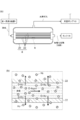
- FIG. 1 is a schematic view showing an embodiment of a hydrogen production method (hydrogen production system) according to the present invention.
- 2a and 2b are schematic views showing a second step provided in an embodiment of the method for producing hydrogen according to the present invention.
- the method for producing hydrogen according to the present embodiment includes a first step of generating hydrogen by dehydrogenation of an organic hydride, and separating hydrogen (hydrogen gas) dissolved in a liquid of an organic compound generated by dehydrogenation from the liquid. And a second step.
- the organic hydride may be, for example, one or more selected from the group consisting of cyclohexane, methylcyclohexane, dimethylcyclohexane, decalin, 1-methyldecalin, 2-methyldecalin and 2-ethyldecalin.
- the “organic compound formed by dehydrogenation” is a dehydrogenated product of an organic hydride (aromatic hydrocarbon, unsaturated cyclic hydrocarbon, etc.), and is at ordinary temperature (about 15 ° C.). It is liquid.
- the dehydration product of organic hydride may be at least one selected from the group consisting of benzene, toluene, xylene, ethylbenzene, tetralin, naphthalene, methylnaphthalene and ethylnaphthalene.
- the organic hydride is methylcyclohexane
- the “organic compound produced by dehydrogenation” is toluene.
- hydrogen is produced using the hydrogen production system 100 shown in FIGS. 1, 2a and 2b.
- the hydrogen production system 100 is a hydrogen production system in a hydrogen station for supplying hydrogen gas as fuel to a fuel cell vehicle, for example.
- organic hydride is supplied into the dehydrogenation reactor 2.
- a dehydrogenation catalyst in the dehydrogenation reactor 2.
- the inside of the dehydrogenation reactor is a reducing atmosphere.
- the dehydrogenation reaction occurs, and at least a pair of hydrogen atoms are extracted from the organic hydride, and a hydrogen molecule, an organic compound such as an aromatic hydrocarbon, Produces.
- the dehydrogenation reaction is a gas phase reaction.
- the dehydrogenation catalyst used in the first step may be a catalyst including, for example, a support and an active metal supported on the support.
- the support may be, for example, one or more selected from the group consisting of alumina (Al 2 O 3 ), silica (SiO 2 ), titania (TiO 2 ), and carbon (activated carbon).
- the alumina may be ⁇ -alumina, ⁇ -alumina, ⁇ -alumina, ⁇ -alumina or alumite.
- the active metal is selected from the group consisting of platinum (Pt), rhodium (Rh), palladium (Pd), nickel (Ni), ruthenium (Ru), iridium (Ir), osmium (Os) and rhenium (Re), for example. It may be one kind or plural kinds.
- the dehydrogenation catalyst may be, for example, a catalyst comprising ⁇ -alumina, platinum supported on ⁇ -alumina, and a Group 3 metal.
- This dehydrogenation catalyst is particularly excellent in dehydrogenation activity and hardly deactivates over time due to the dehydrogenation reaction.
- the Group 3 metal may be one or more selected from scandium (Sc), yttrium (Y), lanthanoid and actinoid.
- the lanthanoid can be, for example, lanthanum (La) or cerium (Ce). Of these Group 3 metals, cerium is relatively preferred.
- the dehydrogenation catalyst can have a remarkably high dehydrogenation activity by containing cerium.
- the product (hydrogen molecule and organic compound) of the dehydrogenation reaction is supplied from the dehydrogenation reactor 2 into the first gas-liquid separator 4.
- the temperature in the first gas-liquid separator 4 is not less than the melting point of the organic compound and less than the boiling point of the organic compound, and may be room temperature (about 15 ° C.).
- the temperature in the first gas-liquid separator 4 may be about ⁇ 94.97 to 110.63 ° C. or 15 ° C.
- the pressure in the 1st gas-liquid separator 4 is a normal pressure (substantially atmospheric pressure). Therefore, the hydrogen molecules in the first gas-liquid separator 4 are gases, and the organic compounds in the first gas-liquid separator 4 are liquids.
- the product of the dehydrogenation reaction is separated into hydrogen gas (gas phase, gas layer) and organic compound liquid (liquid phase, liquid layer).
- a small amount of vapor of an organic compound is mixed in the gas phase.
- the partial pressure of the organic compound in the gas phase is at most about the saturated vapor pressure of the organic compound.
- a part of hydrogen (a trace amount of hydrogen molecules) generated by dehydrogenation is dissolved in the liquid phase.
- organic hydride that has not been dehydrogenated may remain in the liquid phase.
- the gas phase (hydrogen gas) in the first gas-liquid separator 4 is supplied to the hydrogen purifier 6.
- the liquid phase (organic compound liquid) in the first gas-liquid separator 4 is supplied to the second gas-liquid separator. Below, a 2nd gas-liquid separator is described as the deaeration apparatus 8.
- the deaeration device 8 includes a chamber 20 and a plurality of separation membranes 22 arranged in the chamber 20.
- Each separation membrane 22 is a hollow fiber (tube).
- the plurality of separation membranes 22 are bundled.
- FIG. 2B is a cross-sectional view parallel to the longitudinal direction of the separation membrane 22 in a portion b of the separation membrane 22 provided in the deaeration device 8 of FIG. 2A.
- the separation membrane 22 Since the separation membrane 22 has a hollow fiber shape, the surface area per unit volume of the separation membrane 22 is increased as compared with a flat carbon membrane, so that the hydrogen separation ability of the separation membrane 22 is improved. Further, the hollow fiber-shaped separation membrane 22 is excellent in pressure resistance, and is therefore suitable for gas-liquid separation by pressure difference. Furthermore, the hollow fiber-shaped separation membrane 22 is easy to process and has a large surface area per unit volume. Therefore, by using the hollow fiber-shaped separation membrane 22, it is possible to manufacture a deaeration device 8 that is small and excellent in separation performance.
- the inside of the chamber 20 is deaerated and decompressed by the vacuum pump 10.
- the inside of the chamber 20 and the inside of each separation membrane 22 are separated by each separation membrane 22.
- the liquid of the organic compound supplied from the first gas-liquid separator 4 is introduced into the inside of each separation membrane 22 from one end portion of each separation membrane 22.
- Each separation membrane 22 has innumerable pores penetrating the separation membrane 22 in the thickness direction. The pore size is small enough to selectively permeate hydrogen molecules among molecules composed of a plurality of atoms. Therefore, only the hydrogen molecules of the organic compound liquid introduced into the separation membrane 22 and the hydrogen molecules dissolved in the liquid are driven by the pressure difference between the inside of the separation membrane 22 and the inside of the chamber 20. It passes through the separation membrane 22 and moves into the chamber 20.
- Hydrogen molecules (hydrogen gas) moved from the inside of the separation membrane 22 into the chamber 20 are supplied to the low-pressure compressor 12 via the vacuum pump 10 and compressed.
- the hydrogen gas compressed by the low-pressure compressor 12 is further compressed by the high-pressure compressor 14 and then used as fuel for the fuel cell.
- the organic compound liquid inside the separation membrane 22 cannot pass through each separation membrane 22. Therefore, the organic compound liquid in the separation membrane 22 is discharged out of the deaeration device 8 from the other end of each separation membrane 22 after the hydrogen molecules are separated, and is supplied into the tank 16.
- the organic compound in the tank 16 may be reused as an organic hydride by being hydrogenated.
- the organic compound liquid itself is in an atmosphere of normal temperature and normal pressure (substantially atmospheric pressure).
- normal temperature and normal pressure substantially atmospheric pressure
- the separation of hydrogen molecules Liquid degassing
- degas is a method originally intended to remove impurities (gas) from its object (organic compound liquid), and therefore degas selectively collects only a specific gas (hydrogen molecule). Therefore, it is difficult to increase the purity of the gas. Further, if degas using other gas such as nitrogen gas is performed, a process for separating the other gas from the hydrogen gas recovered by degas is further required, which increases the production cost of hydrogen gas. .
- the permeation coefficient of hydrogen molecules in the separation membrane 22 may be 4.0 ⁇ 10 ⁇ 9 to 1.0 ⁇ 10 ⁇ 5 [mol ⁇ m / (m 2 ⁇ s ⁇ Pa)] at 30 ° C.
- the separation membrane 22 may be insoluble in an organic compound liquid. In this case, the separation membrane 22 is hardly deteriorated in the second step, and the selective separation ability of hydrogen molecules in the separation membrane 22 is easily maintained.
- the separation membrane 22 when methylcyclohexane is used as the organic hydride, the separation membrane 22 may be insoluble in toluene produced by dehydrogenation of methylcyclohexane.
- the deterioration of the separation membrane 22 means that the separation membrane 22 is dissolved by the organic compound, the diameter of the pores penetrating the separation membrane 22 is increased, and molecules of the organic compound larger than hydrogen molecules also pass through the separation membrane 22. It means to end up. That is, when the separation membrane is dissolved in the organic compound, the hydrogen separation ability of the separation membrane is reduced.
- the diameter of the pores penetrating the separation membrane 22 in the thickness direction allows permeation of hydrogen molecules having a maximum molecular diameter of 0.289 nm and an organic compound having a molecular diameter larger than that of the hydrogen molecules (for example, the molecular diameter is 0). It is sufficient that the size is such that it does not transmit (toluene of .585 nm). Accordingly, the pore diameter may be, for example, 0.25 to 0.5 nm, 0.25 to 0.3 nm, or 0.3 to 0.5 nm.
- the permeability of each molecule in the separation membrane 22 is the detection limit.
- the upper and lower limit values of the molecular diameter of molecules that are equal to or greater than the value substantially correspond to the upper and lower limit values of the pore diameter of the separation membrane 22.
- the average value of the pore diameter may be, for example, a weighted average value of the molecular diameter of each molecule based on the measured value of the permeability of each molecule, and the integrated value of the number of pores in the pore diameter distribution curve is 50%.
- the pore diameter (d50) may be sufficient.
- the thickness of the separation membrane 22 may be 5 to 100 ⁇ m. Thereby, it becomes easy to achieve both sufficient mechanical strength of the separation membrane 22 and excellent hydrogen separation ability.
- the permeability coefficient of hydrogen molecules at 30 ° C. is 4.0 ⁇ 10 ⁇ 9 [mol ⁇ m / (m 2 ⁇ s ⁇ Pa)] or more, the pore diameter is about 0.5 nm or less, and
- the separation membrane 22 that is insoluble in the liquid may be, for example, a fluororesin membrane, a silica membrane, a zeolite membrane, or a carbon membrane. Since these separation membranes are excellent in hydrogen separation ability and hardly dissolve in organic compounds, the small pore diameter of the separation membrane is maintained, and the separation ability of hydrogen in the separation membrane is unlikely to decrease with time.
- the fluororesin film is made of PTFE (polytetrafluoroethylene), PFA (tetrafluoroethylene / perfluoroalkyl vinyl ether copolymer), FEP (tetrafluoroethylene / hexafluoropropylene copolymer) and ETFE (tetrafluoroethylene / ethylene copolymer). It may be a film composed of at least one or more selected from the group consisting of (polymer). Among these fluororesin films, a film made of PFA is relatively preferable.
- the PFA membrane is particularly excellent in the function of selectively permeating hydrogen dissolved in an organic compound and not permeating the organic compound.
- the zeolite membrane may be a membrane composed of zeolite having an eight-membered ring structure, and a membrane composed of chabazite-type zeolite is relatively preferable.
- the carbon film is not particularly limited.
- a membrane composed of carbon formed by infusibilization (crosslinking by heating) and firing (carbonization) of an organic polymer such as a poly (2,6-dimethyl-1,4-phenylene oxide) derivative is used as the separation membrane 22. May be used as The hollow fiber-shaped separation membrane 22 is manufactured through an extrusion molding process of the above composition or its raw material, or a molding process using a mold.
- the hydrogen gas supplied from the first gas-liquid separator 4 to the hydrogen purification device 6 is purified by the hydrogen purification device 6.
- the hydrogen purification apparatus 6 includes, for example, an outer cylinder (chamber) and a plurality of hollow fiber carbon membranes arranged in the chamber. A plurality of carbon films are bundled. The inside of the chamber and the inside of each carbon film are separated by each carbon film. Hydrogen gas is introduced into the chamber of the hydrogen purifier 6 from the first gas-liquid separator 4. The inside of each carbon film is degassed and depressurized from one end of each carbon film by a vacuum pump. The carbon film has innumerable pores penetrating the carbon film in the thickness direction.
- the pore diameter is small enough to allow only hydrogen molecules to permeate among molecules composed of a plurality of atoms. Accordingly, the hydrogen molecules in the chamber are driven by the pressure difference between the inside of the chamber and the inside of the carbon film, and move from the outside to the inside of the carbon film. The hydrogen gas that has moved from the inside of the chamber to the inside of the carbon film is compressed by the high-pressure compressor 14 and then used as fuel for the fuel cell. On the other hand, organic compounds (including organic hydrides) in the hydrogen gas in the chamber cannot penetrate each carbon film. In the chamber, not only an organic compound but also a trace amount of hydrogen that has not permeated the carbon film may remain as a gas phase (non-permeating gas).
- the gas phase remaining in the chamber may be supplied into the dehydrogenation reactor 2 together with the organic hydride.
- the organic compound existing in the chamber may be recovered into the tank 16.
- the carbon membrane provided in the hydrogen purifier 6 is not particularly limited.
- a hollow fiber-like carbon membrane manufactured by an extrusion process, an infusibilization process (crosslinking by heating), and a firing process (carbonization) of an organic polymer such as a poly (2,6-dimethyl-1,4-phenylene oxide) derivative May be used.
- the hydrogen recovery rate is improved as compared with a conventional hydrogen production method that does not perform the second step.
- Example 1 [First step] 3.6 ml of alumina supporting a platinum (dehydrogenation catalyst layer) was placed in a flow-type dehydrogenation reactor. Methylcyclohexane (molecular diameter: 0.56 nm) and hydrogen gas were supplied into the dehydrogenation reactor and contacted with the dehydrogenation catalyst layer to dehydrogenate methylcyclohexane. In the dehydrogenation reaction, the atmospheric pressure in the dehydrogenation reactor was adjusted to 0.19 MPa. In the dehydrogenation reactor, the temperature at the center of the dehydrogenation catalyst layer was adjusted to 350 ° C. using an external heating device attached to the dehydrogenation reactor.
- the flow rate of methylcyclohexane (gas) brought into contact with the dehydrogenation catalyst was adjusted to 0.18 ml / min.
- the flow rate of hydrogen gas brought into contact with the dehydrogenation catalyst was adjusted to 8.0 ml / min.
- the liquid in the gas-liquid separator was degassed by the following procedure.
- a membrane made of PFA tetrafluoroethylene / perfluoroalkyl vinyl ether copolymer
- the thickness of the separation membrane 22 was 100 ⁇ m.
- the total value of the areas of the plurality of separation membranes 22 included in the deaeration device 8 was 0.5 m 2 .
- the permeability coefficient of hydrogen molecules in the separation membrane 22 was 4.0 ⁇ 10 ⁇ 9 [mol ⁇ m / (m 2 ⁇ s ⁇ Pa)] at 30 ° C.
- the liquid in the gas-liquid separator was introduced into the inside of each separation membrane 22 from one end of each separation membrane 22 provided in the degassing device 8.
- the inside of the chamber 20 included in the degassing device 8 was depressurized by the vacuum pump 10 and the pressure inside the chamber 20 was adjusted to 50 kPa, thereby degassing the liquid inside the separation membrane 22.
- the composition of the gas recovered from the inside of the chamber 20 by the vacuum pump 10 was analyzed by gas chromatography. As a result of analysis, it was confirmed that the gas in the chamber 20 was hydrogen gas. In addition, toluene and methylcyclohexane were not detected in the gas recovered from the inside of the chamber 20.
- the detection limit value of each of toluene and methylcyclohexane by gas chromatography was 1 mol ⁇ ppm.
- the content of hydrogen molecules in the liquid discharged from the separation membrane 22 after deaeration was measured using a dissolved hydrogen meter. Hydrogen molecules were not detected in the liquid after degassing.
- the detection limit value of the hydrogen molecule by a dissolved hydrogen meter was 100 mol ⁇ ppb.
- the hydrogen gas produced by the method for producing hydrogen according to the present invention is applied to, for example, a fuel for a fuel cell.
Landscapes
- Chemical & Material Sciences (AREA)
- Chemical Kinetics & Catalysis (AREA)
- Organic Chemistry (AREA)
- Health & Medical Sciences (AREA)
- General Health & Medical Sciences (AREA)
- Engineering & Computer Science (AREA)
- Combustion & Propulsion (AREA)
- Inorganic Chemistry (AREA)
- Hydrogen, Water And Hydrids (AREA)
- Separation Using Semi-Permeable Membranes (AREA)
- Degasification And Air Bubble Elimination (AREA)
- Fuel Cell (AREA)
Abstract
水素の回収率を向上させることが可能な水素の製造方法及び水素の製造システムを提供する。本発明の一側面に係る水素の製造方法は、有機ハイドライドの脱水素化により水素を生成させる第一工程と、脱水素化によって生成した有機化合物の液体中に溶存する水素を液体から分離する第二工程と、を備える。本発明に係る水素の製造システムの一態様は、有機ハイドライドの脱水素化により水素及び有機化合物を生成させる脱水素反応器2と、有機化合物の液体中に溶存する水素を液体から分離する気液分離器(脱気装置8)と、を備える。
Description
本発明は、水素の製造方法及び水素の製造システムに関する。
近年、環境負荷の小さい水素を燃料とする燃料電池を、自動車等の動力源に用いることが期待されている。水素の輸送、貯蔵及び供給の過程では、下記のように、メチルシクロヘキサン等の有機ハイドライドが利用される。
例えば、水素の製造施設(太陽光発電所等)において、トルエンの水素化により、メチルシクロヘキサンを生成させる。メチルシクロヘキサンを、水素の消費地へ輸送したり、消費地で貯蔵したりする。消費地において、メチルシクロヘキサンの脱水素により、水素とトルエンとを生成させる。この水素を燃料電池へ供給する。トルエンは、水素の製造施設における水素化により、メチルシクロヘキサンとして再利用されてもよい。
上記のように、有機ハイドライドとは、脱水素化反応及び水素化反応によって水素の放出及び吸蔵を可逆的に繰り返すことが可能な有機化合物である。有機ハイドライドは、常温常圧下において液体であり、水素ガスよりも体積が小さく、水素ガスよりも反応性が低く安全である。そのため、有機ハイドライドは水素ガスの単体に比べて輸送及び貯蔵に適している。
有機ハイドライド用の脱水素触媒としては、白金‐レニウムのバイメタルをアルミナ担体に担持させた触媒が知られている(下記非特許文献1参照。)。
R.W.Coughlin, K.Kawakami, Akram Hasan, Journal of Catalysis, Vol. 88, 150‐162 (1984).
有機ハイドライドの実用化のためには、水素の回収率を向上させることが望まれる。ここで、水素の回収率とは、有機ハイドライドの脱水素化によって生成した水素全量のうち回収される水素の割合(単位:モル%等)である。
本発明は、上記従来技術の有する課題に鑑みてなされたものであり、水素の回収率を向上させることが可能な水素の製造方法及び水素の製造システムを提供することを目的とする。
本発明の一側面に係る水素の製造方法は、有機ハイドライドの脱水素化により水素及び有機化合物を生成させる第一工程と、有機化合物の液体中に溶存する水素を液体から分離する第二工程と、を備える。
本発明の一側面に係る水素の製造方法では、第二工程において、上記液体及び上記液体中に溶存する水素のうち水素を選択的に透過させる分離膜により、水素を前記液体から分離してよい。
本発明の一側面に係る水素の製造方法では、第一工程で生成した水素、及び第二工程で上記液体から分離された水素は、燃料電池の燃料として用いられてもよい。
本発明の一側面に係る水素の製造方法では、分離膜における水素の透過係数が、30℃において4.0×10⁻⁹[mol・m/(m2・s・Pa)]以上であってよい。
本発明の一側面に係る水素の製造方法では、分離膜は上記液体に不溶であってよい。
本発明の一側面に係る水素の製造システムは、有機ハイドライドの脱水素化により水素及び有機化合物を生成させる脱水素反応器と、有機化合物の液体中に溶存する水素を液体から分離する気液分離器と、を備える。
本発明の一側面に係る水素の製造システムでは、気液分離器が、上記液体及び上記液体中に溶存する水素のうち水素を選択的に透過させる分離膜を有してよい。
本発明の一側面に係る水素の製造システムは、燃料電池の燃料として用いられる水素を製造するためのものであってよい。
本発明の一側面に係る水素の製造システムでは、分離膜における水素の透過係数は、30℃において4.0×10⁻⁹[mol・m/(m2・s・Pa)]以上であってよい。
本発明の一側面に係る水素の製造システムでは、分離膜は上記液体に不溶であってよい。
本発明によれば、水素の回収率を向上させることが可能な水素の製造方法及び水素の製造システムが提供される。
以下、本発明の好適な実施形態について説明する。ただし、本発明は下記実施形態に何ら限定されるものではない。
本実施形態に係る水素の製造方法は、有機ハイドライドの脱水素化により水素を生成させる第一工程と、脱水素化によって生成した有機化合物の液体中に溶存する水素(水素ガス)を液体から分離する第二工程と、を備える。
有機ハイドライドは、例えば、シクロヘキサン、メチルシクロヘキサン、ジメチルシクロヘキサン、デカリン、1-メチルデカリン、2-メチルデカリン及び2-エチルデカリンからなる群より選ばれる1種又は複数種であってよい。なお本発明において、「脱水素化によって生成した有機化合物」とは、有機ハイドライドの脱水素化物(芳香族炭化水素、又は不飽和環式炭化水素、等)であり、常温(約15℃)において液体である。有機ハイドライドの脱水素化物は、ベンゼン、トルエン、キシレン、エチルベンゼン、テトラリン、ナフタレン、メチルナフタレン及びエチルナフタレンからなる群より選ばれる少なくとも一種であってよい。例えば、有機ハイドライドがメチルシクロヘキサンである場合、「脱水素化によって生成した有機化合物」とはトルエンである。
本実施形態では、図1、図2a及び図2bに示す水素の製造システム100を用いて、水素を製造する。なお、水素の製造システム100とは、例えば燃料電池車に燃料として水素ガスを供給するための水素ステーションにおける水素製造システムである。
第一工程では、有機ハイドライドを脱水素反応器2内へ供給する。脱水素反応器2内には脱水素触媒がある。脱水素反応器内は還元雰囲気である。脱水素反応器2内において有機ハイドライドが脱水素触媒に接触すると、脱水素化反応が起こり、少なくとも一対の水素原子が有機ハイドライドから引き抜かれ、水素分子と、芳香族炭化水素等の有機化合物と、が生成する。このように、脱水素化反応は気相反応である。
第一工程で用いる脱水素触媒は、例えば、担体と、担体に担持された活性金属と、を備える触媒であってよい。担体は、例えば、アルミナ(Al2O3)、シリカ(SiO2)、チタニア(TiO2)及び炭素(活性炭)からなる群より選ばれる一種又は複数種であってよい。アルミナは、γ-アルミナ、α-アルミナ、δ-アルミナ、θ-アルミナ又はアルマイトであってよい。活性金属は、例えば、プラチナ(Pt)、ロジウム(Rh)、パラジウム(Pd)、ニッケル(Ni)、ルテニウム(Ru)、イリジウム(Ir)、オスミウム(Os)及びレニウム(Re)からなる群より選ばれる一種又は複数種であってよい。
脱水素触媒は、例えば、γ-アルミナと、γ-アルミナに担持されたプラチナと、第3族金属と、を備える触媒であってよい。この脱水素触媒は、特に脱水素活性に優れ、また脱水素反応に伴って経時的に失活し難い。第3族金属は、スカンジウム(Sc)、イットリウム(Y)、ランタノイド及びアクチノイドから選ばれる一種又は複数種であってよい。ランタノイドは、例えば、ランタン(La)又はセリウム(Ce)であってよい。これらの第3族金属のうち、セリウムが比較的に好ましい。脱水素触媒は、セリウムを含むことにより、顕著に高い脱水素活性を有することができる。
脱水素化反応の生成物(水素分子及び有機化合物)は、脱水素反応器2から第一気液分離器4内へ供給される。第一気液分離器4内の温度は、有機化合物の融点以上有機化合物の沸点未満であり、常温(約15℃)であってよい。例えば、有機化合物がトルエンである場合、第一気液分離器4内の温度は-94.97~110.63℃程度であってもよく、15℃であってもよい。また、第一気液分離器4内の圧力は常圧(略大気圧)である。したがって、第一気液分離器4内の水素分子は気体であり、第一気液分離器4内の有機化合物は液体である。つまり、第一気液分離器4内において、脱水素化反応の生成物は、水素ガス(気相、気層)と、有機化合物の液体(液相、液層)と、に分離する。気相には、微量の有機化合物の蒸気が混入している。気相における有機化合物の分圧は最大で有機化合物の飽和蒸気圧程度である。一方、液相には、脱水素化によって生成した水素の一部(微量の水素分子)が溶存している。また、液相には、脱水素化されなかった有機ハイドライドが残存していてもよい。第一気液分離器4内の気相(水素ガス)は水素精製装置6へ供給される。第一気液分離器4内の液相(有機化合物の液体)は第二気液分離器へ供給される。以下では、第二気液分離器を脱気装置8と記す。
脱気装置8を用いて第二工程を実施する。図2aに示すように、脱気装置8は、チャンバー20と、チャンバー20内に配置された複数の分離膜22と、を備える。各分離膜22は中空糸(管)である。複数の分離膜22は束ねられている。図2bは、図2aの脱気装置8が備える分離膜22の部分bにおける、分離膜22の長手方向に平行な断面図である。
分離膜22が中空糸状であることにより、分離膜22の単位容積当たりの表面積が、平坦な炭素膜に比べて増加するため、分離膜22の水素の分離能が向上する。また、中空糸状の分離膜22は耐圧性に優れるので、圧力差による気液分離に適している。さらに、中空糸状の分離膜22は加工しやすく、その単位容積当たりの表面積が大きい。したがって、中空糸状の分離膜22を用いることにより、小型で分離能に優れた脱気装置8を製造することが可能となる。
チャンバー20の内部は、真空ポンプ10によって脱気され、減圧される。チャンバー20の内部と各分離膜22の内側とは、各分離膜22によって隔てられている。第一気液分離器4から供給された有機化合物の液体は、各分離膜22の一方の端部から各分離膜22の内側へ導入される。各分離膜22には、分離膜22を厚さ方向に貫通する無数の細孔が形成されている。その細孔径は、複数の原子からなる分子のうち水素分子を選択的に透過させる程度に小さい。したがって、分離膜22の内側に導入された有機化合物の液体と当該液体中に溶存する水素分子のうち水素分子のみが、分離膜22の内側とチャンバー20の内部との圧力差に駆動されて、分離膜22を透過し、チャンバー20の内部へ移動する。分離膜22の内側からチャンバー20内へ移動した水素分子(水素ガス)は、真空ポンプ10を介して、低圧コンプレッサー12へ供給され、圧縮される。低圧コンプレッサー12で圧縮された水素ガスは、高圧コンプレッサー14において更に圧縮された後、燃料電池の燃料として用いられる。一方、分離膜22の内側にある有機化合物の液体は各分離膜22を透過することができない。したがって、分離膜22内の有機化合物の液体は、水素分子が分離された後、各分離膜22の他方の端部から脱気装置8の外へ排出され、タンク16内へ供給される。タンク16内の有機化合物は、水素化されることにより、有機ハイドライドとして再利用されてもよい。以上の方法により、水素分子が液相(有機化合物の液体)から分離される。
上記の第二工程では、有機化合物の液体自体は常温及び常圧(略大気圧)の雰囲気下にあるが、分離膜22の内側とチャンバー20の内部との圧力差によって、水素分子の分離(液体の脱気)を進行させることができる。つまり第二工程では、有機化合物の液体自体の加熱及び加圧を行うことなく、緩和な条件下で、水素分子を有機化合物の液体から効率的に分離することが可能である。
仮に、分離膜22ではなく、窒素ガス等の水素以外のガスを用いた有機化合物のdegas(purge又はbubbling等)によって水素分子を有機化合物の液体から分離する場合、分離された水素ガス中に他のガスが混入してしまう。その結果、最終的に製造される水素ガスの純度が低下する。この方法で製造された水素ガスは、極めて高い純度(例えば99.99~99.9999mol%)が要求される燃料電池用の燃料としては利用困難である。そもそも、degasは、その対象物(有機化合物の液体)から不純物(ガス)を除去することを本来の目的とする方法であるので、degasによって特定のガス(水素分子)のみを選択的に回収してガスの純度を高めることは困難である。また、仮に窒素ガス等の他のガスを用いたdegasを行う場合、degasによって回収された水素ガスから他のガスを分離するための工程が更に必要となり、水素ガスの製造コストが増加してしまう。
分離膜22における水素分子の透過係数が大きいほど、水素分子の分離に要する分離膜の面積、時間及び圧力差を低減することが可能である。つまり、透過係数が大きいほど、より多量の水素分子を有機化合物の液体から分離し、水素の回収率を顕著に向上させることが可能である。分離膜22における水素分子の透過係数は、30℃において、4.0×10⁻⁹~1.0×10⁻⁵[mol・m/(m2・s・Pa)]であればよい。このような透過係数を有する分離膜22を用いることにより、水素分子を効率的に有機化合物の液体から分離することが可能となる。ただし、透過係数が上記範囲外であったとしても、本発明の効果は達成可能である。
分離膜22は、有機化合物の液体に不溶であってよい。この場合、第二工程において分離膜22が劣化し難く、分離膜22における水素分子の選択的分離能が維持され易い。例えば、有機ハイドライドとしてメチルシクロヘキサンを用いる場合、分離膜22は、メチルシクロヘキサンの脱水素化によって生成するトルエンに対して不溶であってよい。なお、分離膜22の劣化とは、分離膜22が有機化合物によって溶解し、分離膜22を貫通する細孔の径が大きくなり、水素分子よりも大きい有機化合物の分子も分離膜22を透過してしまうことを意味する。つまり、分離膜が有機化合物に溶解すると、分離膜の水素の分離能が低下する。
分離膜22をその厚さ方向に貫通する細孔の径は、分子径の最大値が0.289nmである水素分子を透過させ、水素分子よりも分子径が大きい有機化合物(例えば分子径が0.585nmであるトルエン)を透過させない程度の大きさであればよい。したがって、細孔径は、例えば、0.25~0.5nmであってよく、0.25~0.3nmであってもよく、0.3~0.5nmであってもよい。下記のような分子径の異なる複数の分子を用いて、分離膜22における各分子の透過度(分離膜22を透過した分子のモル数)を測定したとき、透過度(モル数)が検出限界値以上である分子の分子径の上下限値が、分離膜22の細孔径の上下限値にほぼ対応する。細孔径の平均値は、例えば、各分子の透過度の測定値に基づく各分子の分子径の加重平均値であってもよく、細孔径の分布曲線における細孔数の積分値が50%となる細孔径(d50)であってもよい。
He(単原子分子径:0.26nm)
H2(分子径:0.289nm)
CO2(分子径:0.33nm)
O2(分子径:0.346nm)
N2(分子径:0.364nm)
CH4(分子径:0.38nm)
トルエン(分子径:0.585nm)
He(単原子分子径:0.26nm)
H2(分子径:0.289nm)
CO2(分子径:0.33nm)
O2(分子径:0.346nm)
N2(分子径:0.364nm)
CH4(分子径:0.38nm)
トルエン(分子径:0.585nm)
分離膜22の厚みは、5~100μmであればよい。これにより分離膜22の十分な機械的強度と優れた水素の分離能とが両立し易くなる。
30℃における水素分子の透過係数が4.0×10⁻⁹[mol・m/(m2・s・Pa)]以上であり、且つ細孔径が約0.5nm以下であり、且つ有機化合物の液体に不溶である分離膜22は、例えば、フッ素樹脂膜、シリカ膜、ゼオライト膜又は炭素膜であってよい。これらの分離膜は、水素の分離能に優れると共に、有機化合物に溶解し難いため、分離膜の小さな孔径が維持され、分離膜の水素の分離能が経時的に低下し難い。
フッ素樹脂膜は、PTFE(ポリテトラフルオロエチレン)、PFA(テトラフルオロエチレン・パーフルオロアルキルビニルエーテル共重合体)、FEP(テトラフルオロエチレン・ヘキサフルオロプロピレン共重合体)及びETFE(テトラフルオロエチレン・エチレン共重合体)からなる群より選ばれる少なくとも一種又は複数種から構成される膜であってよい。これらのフッ素樹脂膜の中でも、PFAから構成される膜が比較的に好ましい。PFA膜は、有機化合物中に溶存した水素を選択的に透過させ、且つ有機化合物を透過させない機能において、特に優れている。またPFA膜は、フッ素樹脂膜の中でも特にトルエン等の有機化合物に溶解し難いため、PFA膜の小さな孔径が維持され、PFA膜の水素の分離能が経時的に低下し難い。ゼオライト膜は、八員環構造を有するゼオライトから構成される膜であってよく、チャバサイト型ゼオライトから構成される膜が比較的に好ましい。炭素膜は、特に限定されない。例えば、ポリ(2,6-ジメチル-1,4-フェニレンオキシド)誘導体等の有機高分子の不融化(加熱による架橋)及び焼成(炭化)によって生成した炭素から構成される膜を、分離膜22として用いてよい。中空糸状の分離膜22は、上記の組成物又はその原料の押出し成形工程、又は型を用いた成形工程を経て製造される。
第一気液分離器4から水素精製装置6へ供給された水素ガスは、水素精製装置6において精製される。水素精製装置6は、例えば、外筒(チャンバー)と、チャンバー内に配置された複数の中空糸状の炭素膜と、を備える。複数の炭素膜は束ねられている。チャンバーの内部と各炭素膜の内側とは、各炭素膜によって隔てられている。水素ガスは、第一気液分離器4から水素精製装置6のチャンバーの内部に導入される。各炭素膜の内側は、各炭素膜の一方の端部から、真空ポンプによって脱気され、減圧される。炭素膜には、炭素膜を厚さ方向に貫通する無数の細孔が形成されている。その細孔径は、複数の原子からなる分子のうち水素分子のみを透過させる程度に小さい。したがって、チャンバー内の水素分子は、チャンバーの内部と炭素膜の内側との気圧差に駆動されて、炭素膜の外側から内側へ移動する。チャンバーの内部から炭素膜の内側へ移動した水素ガスは、高圧コンプレッサー14において圧縮された後、燃料電池の燃料として用いられる。一方、チャンバー内の水素ガス中の有機化合物(有機ハイドライドを含む。)は、各炭素膜を透過することができない。なお、チャンバー内には、気相(非透過ガス)として、有機化合物のみならず、炭素膜を透過しなかった微量の水素が残存していることがある。したがって、チャンバー内の気相に残存した水素を回収するために、チャンバー内に残存した気相を、有機ハイドライドと共に脱水素反応器2内へ供給してもよい。または、チャンバー内に存存した有機化合物を、タンク16内へ回収してもよい。以上の方法により、有機化合物が気相(水素ガス)から分離され、水素ガスが精製される。
水素精製装置6が備える炭素膜は、特に限定されない。例えば、ポリ(2,6-ジメチル-1,4-フェニレンオキシド)誘導体等の有機高分子の押出成形工程、不融化工程(加熱による架橋)及び焼成工程(炭化)によって製造した中空糸状の炭素膜を用いてよい。
本実施形態によれば、第二工程を行わない従来の水素の製造方法に比べて、水素の回収率が向上する。また本実施形態によれば、燃料電池に適した高純度(例えば99.99~99.9999mol%)の水素ガスを製造することが可能となる。
以下、本発明の内容を実施例及び比較例を用いてより詳細に説明するが、本発明は以下の実施例に限定されるものではない。
(実施例1)
[第一工程]
白金を担持したアルミナ(脱水素触媒層)3.6mlを、流通式の脱水素反応器内に設置した。メチルシクロヘキサン(分子径:0.56nm)及び水素ガスを、脱水素反応器内に供給し、脱水素触媒層に接触させ、メチルシクロヘキサンを脱水素化した。脱水素反応では、脱水素反応器内の気圧を0.19MPaに調整した。脱水素反応器では、脱水素反応器に付属の外部加熱装置を用いて、脱水素触媒層の中心部の温度を350℃に調整した。脱水素反応では、脱水素触媒に接触させるメチルシクロヘキサン(気体)の流量を0.18ml/分に調整した。脱水素反応では、脱水素触媒に接触させる水素ガスの流量を8.0ml/分に調整した。
[第一工程]
白金を担持したアルミナ(脱水素触媒層)3.6mlを、流通式の脱水素反応器内に設置した。メチルシクロヘキサン(分子径:0.56nm)及び水素ガスを、脱水素反応器内に供給し、脱水素触媒層に接触させ、メチルシクロヘキサンを脱水素化した。脱水素反応では、脱水素反応器内の気圧を0.19MPaに調整した。脱水素反応器では、脱水素反応器に付属の外部加熱装置を用いて、脱水素触媒層の中心部の温度を350℃に調整した。脱水素反応では、脱水素触媒に接触させるメチルシクロヘキサン(気体)の流量を0.18ml/分に調整した。脱水素反応では、脱水素触媒に接触させる水素ガスの流量を8.0ml/分に調整した。
[第二工程]
上記の脱水素化反応の生成物を、脱水素反応器から気液分離器内へ供給した。気液分離器内の温度を15℃に調整することにより、脱水素化反応の生成物を、気体(水素ガス)と、液体(トルエン、及び脱水素化されずに残存したメチルシクロヘキサン)と、に分離した。液体中の水素分子の含有率を溶存水素計で測定した。液体の水素分子の含有率は5.9mg/Lであった。
上記の脱水素化反応の生成物を、脱水素反応器から気液分離器内へ供給した。気液分離器内の温度を15℃に調整することにより、脱水素化反応の生成物を、気体(水素ガス)と、液体(トルエン、及び脱水素化されずに残存したメチルシクロヘキサン)と、に分離した。液体中の水素分子の含有率を溶存水素計で測定した。液体の水素分子の含有率は5.9mg/Lであった。
続いて、図2a及び図2bに示す脱気装置8を用いて、以下の手順により、気液分離器内の液体の脱気を行った。なお、脱気装置8が備える中空糸状の分離膜22としては、PFA(テトラフルオロエチレン・パーフルオロアルキルビニルエーテル共重合体)からなる膜を用いた。分離膜22の厚さは100μmであった。脱気装置8が備える複数の分離膜22の面積の合計値は0.5m2であった。分離膜22における水素分子の透過係数は、30℃において4.0×10⁻⁹[mol・m/(m2・s・Pa)]であった。
気液分離器内の液体を脱気装置8が備える各分離膜22の一方の端部から各分離膜22の内側へ導入した。同時に、脱気装置8が備えるチャンバー20の内部を、真空ポンプ10によって減圧し、チャンバー20の内部の気圧を50kPaに調整することにより、分離膜22の内側にある液体の脱気を行った。続いて、真空ポンプ10によりチャンバー20の内部から回収された気体の組成を、ガスクロマトグラフィーにより分析した。分析の結果、チャンバー20内の気体は水素ガスであることが確認された。また、チャンバー20の内部から回収した気体中にトルエン及びメチルシクロヘキサンは検出されなかった。なお、ガスクロマトグラフィーによるトルエン及びメチルシクロヘキサンそれぞれの検出限界値は1mol・ppmであった。脱気後に分離膜22内から排出された液体中の水素分子の含有率を、溶存水素計を用いて測定した。脱気後の液体中に水素分子は検出されなかった。なお、溶存水素計による水素分子の検出限界値は100mol・ppbであった。
以上のことから、分離膜22内の水素分子のみが、分離膜22の内側とチャンバー20の内部との圧力差に駆動されて、分離膜22を透過し、減圧されたチャンバー20の内部空間へ移動し、分離膜22内のトルエン及びメチルシクロヘキサンは分離膜22を透過しないことが確認された。つまり、第二工程において、有機化合物の液体中に溶存する水素が液体から分離され、水素分子の回収率が高まることが確認された。
本発明に係る水素の製造方法によって製造される水素ガスは、例えば、燃料電池の燃料に適用される。
2…脱水素反応器、4…第一気液分離器、6…水素精製装置、8…第二気液分離器(脱気装置)、10…真空ポンプ、12…低圧コンプレッサー、14…高圧コンプレッサー、16…タンク、20…チャンバー、22…中空糸状の分離膜、100…水素の製造システム、D‐liquid…液相が流れる方向、D‐H2…水素分子の移動方向。
Claims (10)
- 有機ハイドライドの脱水素化により水素及び有機化合物を生成させる第一工程と、
前記有機化合物の液体中に溶存する水素を前記液体から分離する第二工程と、
を備える、水素の製造方法。 - 前記第二工程において、前記液体及び前記液体中に溶存する前記水素のうち前記水素を選択的に透過させる分離膜により、前記水素を前記液体から分離する、
請求項1に記載の水素の製造方法。 - 前記第一工程で生成した水素、及び前記第二工程で前記液体から分離された水素は、燃料電池の燃料として用いられる、
請求項1又は2に記載の水素の製造方法。 - 前記分離膜における水素の透過係数は、30℃において4.0×10⁻⁹[mol・m/(m2・s・Pa)]以上である、
請求項2又は3に記載の水素の製造方法。 - 前記分離膜は前記液体に不溶である、
請求項2~4のいずれか一項に記載の水素の製造方法。 - 有機ハイドライドの脱水素化により水素及び有機化合物を生成させる脱水素反応器と、
前記有機化合物の液体中に溶存する水素を前記液体から分離する気液分離器と、
を備える、水素の製造システム。 - 前記気液分離器が、前記液体及び前記液体中に溶存する前記水素のうち前記水素を選択的に透過させる分離膜を有する、
請求項6に記載の水素の製造システム。 - 燃料電池の燃料として用いられる水素を製造するための、
請求項6又は7に記載の水素の製造システム。 - 前記分離膜における水素の透過係数は、30℃において4.0×10⁻⁹[mol・m/(m2・s・Pa)]以上である、
請求項7又は8に記載の水素の製造システム。 - 前記分離膜は前記液体に不溶である、
請求項7~9のいずれか一項に記載の水素の製造システム。
Applications Claiming Priority (2)
| Application Number | Priority Date | Filing Date | Title |
|---|---|---|---|
| JP2013113196A JP5945521B2 (ja) | 2013-05-29 | 2013-05-29 | 水素の製造方法及び水素の製造システム |
| JP2013-113196 | 2013-05-29 |
Publications (1)
| Publication Number | Publication Date |
|---|---|
| WO2014192562A1 true WO2014192562A1 (ja) | 2014-12-04 |
Family
ID=51988597
Family Applications (1)
| Application Number | Title | Priority Date | Filing Date |
|---|---|---|---|
| PCT/JP2014/063103 Ceased WO2014192562A1 (ja) | 2013-05-29 | 2014-05-16 | 水素の製造方法及び水素の製造システム |
Country Status (2)
| Country | Link |
|---|---|
| JP (1) | JP5945521B2 (ja) |
| WO (1) | WO2014192562A1 (ja) |
Cited By (2)
| Publication number | Priority date | Publication date | Assignee | Title |
|---|---|---|---|---|
| JP2022110794A (ja) * | 2021-01-19 | 2022-07-29 | 株式会社日本トリム | 水処理装置及び水処理方法 |
| CN115768717A (zh) * | 2020-07-10 | 2023-03-07 | 阿科玛法国公司 | 用于改善带有氢的有机液体的品质的工艺 |
Families Citing this family (2)
| Publication number | Priority date | Publication date | Assignee | Title |
|---|---|---|---|---|
| JP2016169133A (ja) * | 2015-03-13 | 2016-09-23 | 富士電機株式会社 | 水素製造装置及び水素製造方法 |
| JP2021155312A (ja) * | 2020-03-30 | 2021-10-07 | Eneos株式会社 | 水素供給システム |
Citations (6)
| Publication number | Priority date | Publication date | Assignee | Title |
|---|---|---|---|---|
| JPS63188382A (ja) * | 1987-01-31 | 1988-08-03 | Meidensha Electric Mfg Co Ltd | 嫌気性脂肪酸分解菌等の培養装置 |
| JPH0288214U (ja) * | 1988-12-27 | 1990-07-12 | ||
| JPH07278021A (ja) * | 1994-04-13 | 1995-10-24 | Asahi Chem Ind Co Ltd | スチレンモノマー精製方法 |
| JP2000191557A (ja) * | 1999-01-01 | 2000-07-11 | Denki Kagaku Kogyo Kk | スチレン類の精製方法 |
| JP2003505352A (ja) * | 1999-07-19 | 2003-02-12 | ユーオーピー エルエルシー | フェニル−アルカンを製造する方法、その方法で製造される組成物、及び、その使用 |
| JP2010006653A (ja) * | 2008-06-27 | 2010-01-14 | Japan Energy Corp | 水素製造方法 |
-
2013
- 2013-05-29 JP JP2013113196A patent/JP5945521B2/ja active Active
-
2014
- 2014-05-16 WO PCT/JP2014/063103 patent/WO2014192562A1/ja not_active Ceased
Patent Citations (6)
| Publication number | Priority date | Publication date | Assignee | Title |
|---|---|---|---|---|
| JPS63188382A (ja) * | 1987-01-31 | 1988-08-03 | Meidensha Electric Mfg Co Ltd | 嫌気性脂肪酸分解菌等の培養装置 |
| JPH0288214U (ja) * | 1988-12-27 | 1990-07-12 | ||
| JPH07278021A (ja) * | 1994-04-13 | 1995-10-24 | Asahi Chem Ind Co Ltd | スチレンモノマー精製方法 |
| JP2000191557A (ja) * | 1999-01-01 | 2000-07-11 | Denki Kagaku Kogyo Kk | スチレン類の精製方法 |
| JP2003505352A (ja) * | 1999-07-19 | 2003-02-12 | ユーオーピー エルエルシー | フェニル−アルカンを製造する方法、その方法で製造される組成物、及び、その使用 |
| JP2010006653A (ja) * | 2008-06-27 | 2010-01-14 | Japan Energy Corp | 水素製造方法 |
Cited By (3)
| Publication number | Priority date | Publication date | Assignee | Title |
|---|---|---|---|---|
| CN115768717A (zh) * | 2020-07-10 | 2023-03-07 | 阿科玛法国公司 | 用于改善带有氢的有机液体的品质的工艺 |
| JP2022110794A (ja) * | 2021-01-19 | 2022-07-29 | 株式会社日本トリム | 水処理装置及び水処理方法 |
| JP7514191B2 (ja) | 2021-01-19 | 2024-07-10 | 株式会社日本トリム | 水処理装置及び水処理方法 |
Also Published As
| Publication number | Publication date |
|---|---|
| JP5945521B2 (ja) | 2016-07-05 |
| JP2014231461A (ja) | 2014-12-11 |
Similar Documents
| Publication | Publication Date | Title |
|---|---|---|
| Li et al. | Preparation of a novel bimodal catalytic membrane reactor and its application to ammonia decomposition for COx-free hydrogen production | |
| JP5215057B2 (ja) | 水素製造方法 | |
| Li et al. | Efficient dehydration of the organic solvents through graphene oxide (GO)/ceramic composite membranes | |
| Wang et al. | Preparation of cellulose acetate membrane filled with metal oxide particles for the pervaporation separation of methanol/methyl tert-butyl ether mixtures | |
| US20140137734A1 (en) | Cross-linked polyimide membranes for separations | |
| JP5945521B2 (ja) | 水素の製造方法及び水素の製造システム | |
| CN104822440A (zh) | 用于气体分离的含有氟化乙烯-丙烯聚合物的共混聚合物膜 | |
| CN102159528A (zh) | 醇的制造方法、利用该醇的制造方法的氢或合成气的制造方法、以及醇 | |
| JP4801359B2 (ja) | 水素製造方法 | |
| Manshad et al. | Membranes with favorable chemical materials for pervaporation process: A review | |
| Trinh et al. | Pervaporative separation of butanol using a composite PDMS/PEI hollow fiber membrane | |
| Gallardo et al. | High-flux thin-film nanocomposite membrane enabled by ZIF-8–sulfobetaine–dopamine nanoparticles for pervaporation | |
| JPWO2009048114A1 (ja) | ガス精製方法 | |
| JP5102932B2 (ja) | 高純度水素製造方法 | |
| US8203028B2 (en) | Processes for olefin/paraffin separation utilizing porous, hydrophobic poly(ether ether ketone) membranes | |
| CN1946631A (zh) | 通过选择透过性膜型反应器进行的烃的二氧化碳改质方法 | |
| JP2011230035A (ja) | ガス分離方法 | |
| CN120603800A (zh) | 由丙烷制备丙烯和氢的方法和设备 | |
| JP2016040218A (ja) | 脱水素化システム、及び脱水素化システムの運転方法 | |
| JP2016175063A (ja) | 膜の再生方法 | |
| Akamatsu et al. | Hydrogen produced from simulated biogas using a membrane reactor with a dimethoxydimethylsilane-derived silica membrane operated under pressure and without sweep gas | |
| JP4703464B2 (ja) | 水素分離ユニット、水素製造装置及び予備膜 | |
| Xiaoling et al. | Permeation characteristics of light hydrocarbons through poly (amide-6-β-ethylene oxide) multilayer composite membranes | |
| US20230135291A1 (en) | Hydrogen supply system | |
| JP2010188241A (ja) | ガス精製方法 |
Legal Events
| Date | Code | Title | Description |
|---|---|---|---|
| 121 | Ep: the epo has been informed by wipo that ep was designated in this application |
Ref document number: 14804594 Country of ref document: EP Kind code of ref document: A1 |
|
| NENP | Non-entry into the national phase |
Ref country code: DE |
|
| 122 | Ep: pct application non-entry in european phase |
Ref document number: 14804594 Country of ref document: EP Kind code of ref document: A1 |