WO2014192514A1 - Film forming device - Google Patents
Film forming device Download PDFInfo
- Publication number
- WO2014192514A1 WO2014192514A1 PCT/JP2014/062363 JP2014062363W WO2014192514A1 WO 2014192514 A1 WO2014192514 A1 WO 2014192514A1 JP 2014062363 W JP2014062363 W JP 2014062363W WO 2014192514 A1 WO2014192514 A1 WO 2014192514A1
- Authority
- WO
- WIPO (PCT)
- Prior art keywords
- film forming
- unit
- chamber
- roller
- process chamber
- Prior art date
Links
Images


Classifications
-
- H—ELECTRICITY
- H01—ELECTRIC ELEMENTS
- H01J—ELECTRIC DISCHARGE TUBES OR DISCHARGE LAMPS
- H01J37/00—Discharge tubes with provision for introducing objects or material to be exposed to the discharge, e.g. for the purpose of examination or processing thereof
- H01J37/32—Gas-filled discharge tubes
- H01J37/32431—Constructional details of the reactor
- H01J37/32733—Means for moving the material to be treated
- H01J37/32752—Means for moving the material to be treated for moving the material across the discharge
- H01J37/32761—Continuous moving
- H01J37/3277—Continuous moving of continuous material
-
- C—CHEMISTRY; METALLURGY
- C23—COATING METALLIC MATERIAL; COATING MATERIAL WITH METALLIC MATERIAL; CHEMICAL SURFACE TREATMENT; DIFFUSION TREATMENT OF METALLIC MATERIAL; COATING BY VACUUM EVAPORATION, BY SPUTTERING, BY ION IMPLANTATION OR BY CHEMICAL VAPOUR DEPOSITION, IN GENERAL; INHIBITING CORROSION OF METALLIC MATERIAL OR INCRUSTATION IN GENERAL
- C23C—COATING METALLIC MATERIAL; COATING MATERIAL WITH METALLIC MATERIAL; SURFACE TREATMENT OF METALLIC MATERIAL BY DIFFUSION INTO THE SURFACE, BY CHEMICAL CONVERSION OR SUBSTITUTION; COATING BY VACUUM EVAPORATION, BY SPUTTERING, BY ION IMPLANTATION OR BY CHEMICAL VAPOUR DEPOSITION, IN GENERAL
- C23C14/00—Coating by vacuum evaporation, by sputtering or by ion implantation of the coating forming material
- C23C14/22—Coating by vacuum evaporation, by sputtering or by ion implantation of the coating forming material characterised by the process of coating
- C23C14/56—Apparatus specially adapted for continuous coating; Arrangements for maintaining the vacuum, e.g. vacuum locks
- C23C14/562—Apparatus specially adapted for continuous coating; Arrangements for maintaining the vacuum, e.g. vacuum locks for coating elongated substrates
-
- H—ELECTRICITY
- H01—ELECTRIC ELEMENTS
- H01J—ELECTRIC DISCHARGE TUBES OR DISCHARGE LAMPS
- H01J37/00—Discharge tubes with provision for introducing objects or material to be exposed to the discharge, e.g. for the purpose of examination or processing thereof
- H01J37/32—Gas-filled discharge tubes
- H01J37/32431—Constructional details of the reactor
- H01J37/32458—Vessel
- H01J37/32513—Sealing means, e.g. sealing between different parts of the vessel
-
- H—ELECTRICITY
- H01—ELECTRIC ELEMENTS
- H01J—ELECTRIC DISCHARGE TUBES OR DISCHARGE LAMPS
- H01J37/00—Discharge tubes with provision for introducing objects or material to be exposed to the discharge, e.g. for the purpose of examination or processing thereof
- H01J37/32—Gas-filled discharge tubes
- H01J37/32431—Constructional details of the reactor
- H01J37/32733—Means for moving the material to be treated
-
- H—ELECTRICITY
- H01—ELECTRIC ELEMENTS
- H01J—ELECTRIC DISCHARGE TUBES OR DISCHARGE LAMPS
- H01J37/00—Discharge tubes with provision for introducing objects or material to be exposed to the discharge, e.g. for the purpose of examination or processing thereof
- H01J37/32—Gas-filled discharge tubes
- H01J37/32431—Constructional details of the reactor
- H01J37/32798—Further details of plasma apparatus not provided for in groups H01J37/3244 - H01J37/32788; special provisions for cleaning or maintenance of the apparatus
- H01J37/32807—Construction (includes replacing parts of the apparatus)
-
- H—ELECTRICITY
- H01—ELECTRIC ELEMENTS
- H01J—ELECTRIC DISCHARGE TUBES OR DISCHARGE LAMPS
- H01J37/00—Discharge tubes with provision for introducing objects or material to be exposed to the discharge, e.g. for the purpose of examination or processing thereof
- H01J37/32—Gas-filled discharge tubes
- H01J37/32431—Constructional details of the reactor
- H01J37/32798—Further details of plasma apparatus not provided for in groups H01J37/3244 - H01J37/32788; special provisions for cleaning or maintenance of the apparatus
- H01J37/3288—Maintenance
-
- H—ELECTRICITY
- H01—ELECTRIC ELEMENTS
- H01J—ELECTRIC DISCHARGE TUBES OR DISCHARGE LAMPS
- H01J37/00—Discharge tubes with provision for introducing objects or material to be exposed to the discharge, e.g. for the purpose of examination or processing thereof
- H01J37/32—Gas-filled discharge tubes
- H01J37/32431—Constructional details of the reactor
- H01J37/32798—Further details of plasma apparatus not provided for in groups H01J37/3244 - H01J37/32788; special provisions for cleaning or maintenance of the apparatus
- H01J37/32899—Multiple chambers, e.g. cluster tools
-
- H—ELECTRICITY
- H01—ELECTRIC ELEMENTS
- H01J—ELECTRIC DISCHARGE TUBES OR DISCHARGE LAMPS
- H01J37/00—Discharge tubes with provision for introducing objects or material to be exposed to the discharge, e.g. for the purpose of examination or processing thereof
- H01J37/32—Gas-filled discharge tubes
- H01J37/34—Gas-filled discharge tubes operating with cathodic sputtering
- H01J37/3411—Constructional aspects of the reactor
- H01J37/3414—Targets
- H01J37/3417—Arrangements
-
- H—ELECTRICITY
- H01—ELECTRIC ELEMENTS
- H01J—ELECTRIC DISCHARGE TUBES OR DISCHARGE LAMPS
- H01J37/00—Discharge tubes with provision for introducing objects or material to be exposed to the discharge, e.g. for the purpose of examination or processing thereof
- H01J37/32—Gas-filled discharge tubes
- H01J37/34—Gas-filled discharge tubes operating with cathodic sputtering
- H01J37/3411—Constructional aspects of the reactor
- H01J37/3447—Collimators, shutters, apertures
-
- H—ELECTRICITY
- H01—ELECTRIC ELEMENTS
- H01L—SEMICONDUCTOR DEVICES NOT COVERED BY CLASS H10
- H01L21/00—Processes or apparatus adapted for the manufacture or treatment of semiconductor or solid state devices or of parts thereof
- H01L21/67—Apparatus specially adapted for handling semiconductor or electric solid state devices during manufacture or treatment thereof; Apparatus specially adapted for handling wafers during manufacture or treatment of semiconductor or electric solid state devices or components ; Apparatus not specifically provided for elsewhere
- H01L21/67005—Apparatus not specifically provided for elsewhere
- H01L21/67011—Apparatus for manufacture or treatment
- H01L21/67132—Apparatus for placing on an insulating substrate, e.g. tape
-
- H—ELECTRICITY
- H01—ELECTRIC ELEMENTS
- H01J—ELECTRIC DISCHARGE TUBES OR DISCHARGE LAMPS
- H01J2237/00—Discharge tubes exposing object to beam, e.g. for analysis treatment, etching, imaging
- H01J2237/16—Vessels
- H01J2237/162—Open vessel, i.e. one end sealed by object or workpiece
-
- H—ELECTRICITY
- H01—ELECTRIC ELEMENTS
- H01J—ELECTRIC DISCHARGE TUBES OR DISCHARGE LAMPS
- H01J2237/00—Discharge tubes exposing object to beam, e.g. for analysis treatment, etching, imaging
- H01J2237/20—Positioning, supporting, modifying or maintaining the physical state of objects being observed or treated
- H01J2237/202—Movement
- H01J2237/20278—Motorised movement
-
- H—ELECTRICITY
- H01—ELECTRIC ELEMENTS
- H01J—ELECTRIC DISCHARGE TUBES OR DISCHARGE LAMPS
- H01J2237/00—Discharge tubes exposing object to beam, e.g. for analysis treatment, etching, imaging
- H01J2237/32—Processing objects by plasma generation
- H01J2237/33—Processing objects by plasma generation characterised by the type of processing
- H01J2237/332—Coating
Definitions
- the present invention relates to a continuous film forming apparatus for forming a thin film such as a functional thin film on the surface of a belt-shaped film forming material.
- the film-forming material is continuously transported in a vacuum chamber and is applied to the surface.
- a film in which various functional thin films are formed by sputtering or vapor deposition is known.
- Patent Document 1 discloses an apparatus having an upper chamber and a lower chamber as such a film forming apparatus.
- the lower chamber accommodates a film forming roller on which a film forming material made of a film or the like can be wound, and a plurality of sputtering sources for performing a film forming process on the film forming material.
- the lower chamber has left and right side walls. Openings are formed in these side walls, and a door for opening and closing the opening is mounted on the side walls. With the door open, various maintenance operations such as replacement of targets for each batch process, replacement and cleaning of masks defining the film formation region, and so-called paper passing and replacement of film forming materials are performed through the opening.
- the upper chamber is disposed above the lower chamber, and an unwinding unit for unwinding the film forming material and heating the unwound film forming material to separate gas from the film forming material.
- the film forming material unwound from the unwinding unit in the upper chamber is once carried into the lower chamber after passing through the degassing unit, and after being subjected to film forming treatment, It is returned to the upper chamber and taken up by the take-up unit.
- the present invention is a film forming apparatus including a plurality of units including a film forming unit, wherein the units of the film forming process equipped in the film forming unit are arranged without overlapping these units vertically.
- An object of the present invention is to provide a device that can secure a wide work space for replacement and maintenance.
- a film forming apparatus performs film formation on the surface of a film forming material while conveying a belt-shaped film forming material extending in a specific direction in the longitudinal direction, and a film forming unit; An upstream unit disposed upstream of the film forming unit in the transport direction of the film forming material; and a downstream unit disposed downstream of the film forming unit in the transport direction of the film forming material.
- the film forming unit includes a film forming roller that can rotate around a horizontal rotation center axis, a plurality of film forming process devices disposed around the film forming roller, the upstream unit, and the downstream unit.
- a plurality of guide rollers arranged so as to guide the film forming material to and from the film forming roller, a film forming roller accommodating portion for accommodating the film forming roller, and the guide roller located above the guide roller
- a main chamber having a guide roller accommodating portion for accommodating at least a part thereof, and a left and right direction orthogonal to the direction of the central axis of the film forming roller, respectively, on both sides of the film forming roller accommodating portion, and for the film forming process
- a first process chamber and a second process chamber each housing at least a part of the apparatus and having an opening facing the film forming roller housing portion side; and the first and second processes. It has a process chamber support portion for supporting the Yanba, the.
- the film formation roller accommodating portions are located on both sides of the film formation roller in the left-right direction, and the left and right first chamber opening side surfaces coincide with the openings on the film formation roller accommodating portion side of the first and second process chambers.
- the guide roller accommodating portion has portions extending on both sides in the left-right direction with respect to the left and right first chamber opening side surfaces of the film forming roller accommodating portion, and these portions are respectively provided in the upstream unit and the downstream unit. It has left and right second chamber opening side surfaces to be connected.
- the process chamber support part includes a normal position where the process chamber covers the opening of the film formation roller accommodating part and forms a film formation space together with the main chamber, and a normal position from the normal position.
- the upper unit and the downstream unit are movably supported between a retreat position and a retreat position that retreats to the outside in the left-right direction within a range inside the downstream unit, and the rotation center of the film forming roller from the retreat position and the retreat position. It is supported so as to be movable between an exposure position at which the inside of the process chamber is exposed at a position separated in the front-rear direction which is a direction parallel to the axis.
- horizontal in the present invention is not strictly defined, and is a concept including a direction slightly inclined with respect to a complete horizontal plane.
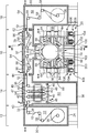
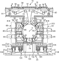
- FIG. 5 is a cross-sectional front view of the film forming apparatus according to the embodiment of the present invention, which is a cross-sectional view taken along the line II of FIG. It is a cross-sectional front view which shows the principal part of the said film-forming apparatus.
- FIG. 3 is a sectional view taken along line III-III in FIG. 1. It is a top view of the film-forming apparatus.
- the film forming apparatus shown in FIG. 1 is an apparatus for forming a thin film on the surface of a film forming material 10 while conveying a long, belt-shaped film forming material 10 made of, for example, a plastic film in the longitudinal direction thereof. It is.
- the film forming apparatus includes an unwinding unit 12, a degassing unit 14, a film forming unit 16, and a winding unit 18 in the order of the film forming material 10.
- the units 12, 14, 16, and 18 are arranged in order along the horizontal direction that is the conveyance direction of the film forming material 10.
- the horizontal direction (including the case where it is slightly inclined) perpendicular to the rotation center axis X of the film forming roller 70 described later corresponds to the left-right direction
- the direction parallel to the rotation center axis X corresponds to the front-rear direction.
- the units 12, 14, 16 and 18 are arranged in that order in the left-right direction (in the direction from left to right in FIG. 1).
- the unwinding unit 12 supplies the film forming material 10, and includes an unwinding roll 26, a plurality of free rollers 28 each serving as a guide roller, and an unwinding chamber 24 surrounding the supply space 22. And a door 30.
- the unwinding roll 26 is accommodated in the lower part of the unwinding chamber 24, and the film forming material 10 wound around the unwinding roll 26 is sequentially unwound by the rotation of the unwinding roll 26.
- Each free roller 28 is disposed above the unwinding roll 26 in the unwinding chamber 24, and the film forming material 10 unwound from the unwinding roll 26 is provided on the upper portion of the unwinding chamber 24. Guide to exit 32.
- the unwinding chamber 24 has an opening that opens the supply space 22 to the outside of the unwinding chamber 24, and the door 30 is attached to the unwinding chamber 24 via a hinge so as to open and close the opening. It is done.
- the opening is used for replacement of the unwinding roll 26, so-called paper passing of the film forming material 10, and other maintenance work.
- the degassing unit 14 heats the unwound film forming material 10 and separates the gas contained therein from the film forming material 10 as a pretreatment process for film formation.
- the degassing chamber 36 includes a roller 40, a plurality of plate heaters 42, a degassing chamber 36 surrounding the degassing space 34, and a support frame 38 disposed below the degassing chamber 36. The free roller 40 and the plate heater 42 are accommodated therein.
- the degassing chamber 36 has an inlet 43 connected to the outlet 32 of the unwinding unit 12 and an outlet 44 located on the opposite side thereof.
- the support frame 38 supports the degassing chamber 36 at a height position where the inlet 43 and the outlet 32 match.
- the degassing chamber 36 includes a top cover 45 and a bottom cover 46 that are positioned above and below, each having an opening for maintenance, and doors 47 and 48 for opening and closing the opening are attached via hinges.
- the support frame 38 surrounds a work space 50 in which an operator can enter below the degassing chamber 36 in order to enable work from an opening provided in the bottom lid 46.
- the free rollers 40 are alternately arranged up and down so as to guide the film-forming material 10 from the inlet 43 to the outlet 44 while being transported up and down in the degassing chamber 36.
- Each of the plate heaters 42 is disposed in an upright position between portions adjacent to each other in the left-right direction of the film forming material 10 that moves in the left-right direction while being conveyed in the up-down direction as described above.
- the film forming material 10 is heated by its own heat generation, and degassing processing is executed.
- the film forming unit 16 performs a film forming process (sputtering in this embodiment) on the surface of the film forming material 10 introduced from the unwinding unit 12 via the degassing unit 14. Details thereof will be described later.
- the winding unit 18 winds the film forming material 10 on which film formation has been performed in the film forming unit 16, and includes a winding chamber 54 surrounding the winding space 52, and the winding chamber.
- a take-up roll 56 and a plurality of free rollers 58 housed in 52 and a door 60 are provided.
- the take-up roll 56 is accommodated in the lower part of the take-up chamber 54, and the film forming material 10 introduced from the film forming unit 16 is sequentially taken up by the rotation of the take-up roll 56.
- Each of the free rollers 58 is disposed above the winding roll 56, and the film-forming material 10 introduced into the winding space 52 from an inlet 62 provided at the upper portion of the winding chamber 54 is wound around the winding roller 56.
- the winding chamber 54 has an opening that opens the winding space 52 to the outside of the winding chamber 54, and the door 60 is connected to the winding chamber 54 via a hinge so as to open and close the opening. Mounted. The opening is used for replacement of the take-up roll 56, so-called paper passing of the film forming material 10, and other maintenance work.
- the film forming unit 16 includes a main chamber 64, a left process chamber (first process chamber) 66, a right process chamber (second process chamber) 68, a film forming roller 70, and a plurality of free rollers.
- the main chamber 64 is formed by integrally connecting a film forming roller housing portion 74 and a guide roller housing portion 76, and constitutes a main chamber unit together with the housing material.
- the film formation roller storage portion 74 stores the film formation roller 70, the auxiliary roller 71, a plurality of film formation masks 203, a part of the pressure separation partition wall 88, and the like, and the guide roller
- the accommodating portion 76 accommodates the guide roller 72.
- the film formation roller accommodating portion 74 has left and right first chamber opening side surfaces 77, and large openings 80 are formed in the respective opening side surfaces 77.
- the internal space of the film forming roller accommodating portion 74 can communicate with the internal spaces of the left and right process chambers 66 and 68 through the openings 80.
- the guide roller accommodating portion 76 is located above the film forming roller accommodating portion 74 and has a shape longer than the film forming roller accommodating portion 74 in the left-right direction, that is, in the direction parallel to the conveyance direction of the film forming material 10. Have. In other words, both end portions of the guide roller housing portion 76 in the left-right direction protrude beyond the film forming roller housing portion 74 in the left-right direction. The end surfaces of these portions correspond to the side surfaces of the second chamber opening, and the inlet 81 and the outlet 82 of the main chamber 64 are formed on the side surfaces of the second chamber opening, respectively.
- the chamber support part 20 supports the main chamber 64 at such height that the inlet 81 and the outlet 82 are connected to the outlet 44 of the degassing unit 14 and the inlet 62 of the winding unit 18, respectively.
- the main chamber 64 shown in FIGS. 1 and 2 is integrally formed as a whole, but the present invention is not limited to this.
- the film forming roller housing portion 74 and the guide roller 76 housing portion may be formed separately for the convenience of manufacture and then combined.
- the film forming roller 70 has a cylindrical outer peripheral surface centering on the rotation center axis X parallel to the front-rear direction of the apparatus, and the film forming material 10 is wound around the outer peripheral surface.
- the film forming roller accommodating portion 74 is supported so as to be rotatable around the axis X.
- the partition wall 88 accommodated in the film forming roller accommodating portion 74 and the partition walls 88 accommodated in the first and second process chambers 66 and 68 form a plurality of spaces around the film forming roller 70.
- the film is divided into film zones 204 and the pressures of the respective film formation zones 204 are separated from each other.
- each film formation mask 203 having an opening is disposed in the vicinity of the outer peripheral surface of the film formation roller 70, and only the portion of the film forming material 10 corresponding to the opening of each film formation mask 203 is sputtered. The deposition area is limited so that the film adheres.
- the left and right auxiliary rollers 71 are disposed immediately above the film forming roller 70, and the film forming material 10 is wound on a surface of the outer peripheral surface of the film forming roller 70 except for the upper end portion thereof. In this way, the film forming material 10 is guided.
- These auxiliary rollers 71 may be accommodated in the guide roller accommodating portion 76 instead of the film forming roller accommodating portion 74.
- Each auxiliary roller 71 can also be used as a tension detection roller for detecting the tension of the film forming material 10.
- the guide rollers 72 are arranged in the guide roller accommodating portion 76 so as to be lined up in the left-right direction. Some of these guide rollers 72 are arranged to guide the film forming material 10 from the degassing unit 14 to the film forming roller 70, and the rest are formed from the film forming roller 70 to the winding unit 18. It arrange
- These guide rollers 72 may include a driven water cooling roller.
- the rollers included in the film forming apparatus are all disposed so as to be rotatable around an axis parallel to the rotation center axis X of the film forming roller 70 (that is, an axis extending in the front-rear direction of the apparatus).
- the film forming material 10 is conveyed in a direction perpendicular to these axes.
- the left and right process chambers 66 and 68 are disposed so as to block the openings 80 provided on the left and right opening side surfaces 77 of the film formation roller accommodating portion 74 from both the left and right outer sides, and cooperate with the film formation roller accommodating portion 74.
- a film forming space that is, a plurality of film forming zones 204 defined by the partition walls 88 are formed around the film forming roller 70.
- Each of the process chambers 66 and 68 accommodates at least a part of the film forming process equipment, and constitutes a process chamber unit that can move with respect to the main chamber unit together with the contents.
- Each film forming process device is disposed along the outer peripheral surface of the film forming roller 70, and the film forming process is performed on the film forming material 10 that moves in the rotation direction on the outer peripheral surface of the film forming roller 70. Execute.
- the film forming process equipment accommodated in the process chambers 66 and 68 includes a plurality of sputtering sources 84, a plurality of turbo molecular pumps 86, a part of the plurality of partition walls 88, a cold trap (not shown), and the like. included.
- Each of the sputtering sources 84 holds a target 85 for sputtering, and is disposed in each of the deposition zones 204 surrounded by the partition walls 88 provided at a plurality of positions in the deposition unit 16.
- Each turbo molecular pump 86 operates to evacuate the process chambers 66 and 68.
- Each of the process chambers 66 and 68 has a shape that opens inward, that is, a box shape that opens toward the film formation roller 70 and the film formation roller accommodating portion 74 that accommodates the film formation roller 70.
- each of the process chambers 66 and 68 has an outer wall 90 positioned on both the left and right outer sides, and a peripheral wall 92 extending inward from the peripheral edge of the outer wall 90. Accordingly, the left and right first chamber opening side surfaces 77 of the film forming roller accommodating portion 74 coincide with the openings on the film forming roller accommodating portion 74 side of the respective process chambers 66 and 68.
- Each of the process chambers 66 and 68 is supported by a chamber support unit 20 described in detail later, and is allowed to move between a normal position indicated by a solid line in FIG. 2 and a retracted position indicated by a two-dot chain line in FIG. Has been.
- each process chamber 66, 68 closes the opening 80 (in this embodiment, a seal member 79 (inner end surface of the peripheral wall 92 of each process chamber 66, 68 is disposed around the opening 80).
- the inside of the film forming roller accommodating portion 74 is sealed, and a plurality of film forming zones 204 are formed in cooperation with the film forming roller accommodating portion 74.
- the retracted position is a position where the process chambers 66 and 68 are retracted from the normal position with a slight stroke outward in the left-right direction, and when the process chambers 66 and 68 move in the front-rear direction from this position, the process is performed. This is a position where interference between the chambers 66 and 68 and the film forming roller 70 can be avoided.
- the stroke from the normal position to the retracted position is set large enough to allow the process chambers 66 and 68 to move in the front-rear direction without interfering with the film forming roller 70 from the retracted position, and Interference between the process chambers 66 and 68 and the units adjacent to the left and right outer sides (the degassing unit 14 that is the upstream unit and the winding unit 18 that is the downstream unit in this embodiment) can be avoided in the retracted position. It is set as small as possible.
- many of the sputtering source 84, the turbo molecular pump 86, and the partition wall 88 are fixed to the outer wall 90 and the peripheral wall 92 of the process chambers 66 and 68, respectively, and the remainder of the partition wall 88 is the It is fixed to the inner wall of the main chamber 64.
- the guide roller accommodating portion 76 has a canopy 94, and a plurality of openings (in this embodiment, a central opening 95 and left and right openings 96) are formed in the canopy 94, and the openings 95 and 96 are opened and closed, respectively. Doors 97 and 98 are attached via hinges.
- the openings 95 and 96 allow the worker to access the guide rollers 72 from above through the openings 95 and 96 by opening the guide rollers 72 accommodated in the guide roller accommodating portion 76 upward. Make it possible.
- the chamber support unit 20 includes a base 100 installed on the ground, a plurality of support columns 102 erected on the base 100, a guide rail 110, which will be described later, and the like assembled on the base 100.
- Left and right process chamber supports 104 The column 102 supports the main chamber 64 of the film forming unit 16 in a stationary state.
- the left and right process chamber support sections 104 support the left and right process chambers 66 and 68 so as to be movable between the normal position and a position retracted from the normal position.
- Each process chamber support section 104 includes a first support section 106 and a second support section 108.
- Each first support portion 106 guides the process chambers 66 and 68 in the left-right direction orthogonal to the central axis of the film forming roller 70, so that the process chambers 66 and 68 are in the normal positions, that is, each process chamber 66. , 68 to allow the process chambers 66, 68 to move between a position for closing the opening 80 of the main chamber 64 and a retreat position for retreating from the normal position to both outsides in the left-right direction. Support each one.
- the second support unit 108 supports the process chambers 66 and 68 and the first support unit 106 that supports the process chambers 66 and 68 so as to be movable in the front-rear direction parallel to the central axis of the film forming roller 70.
- Each second support portion 108 has a pair of guide rails 110 and a pair of traveling bodies 112.
- Each guide rail 110 is laid on the base 100 so as to extend in the front-rear direction.
- Each traveling body 112 travels along each rail 110 while supporting the first support portion 106 from below.
- the traveling body 112 includes a plurality of wheels 114 that can roll on the respective guide rails 110, and a traveling platform 116 that holds these wheels 114 so as to be rotatable about a left-right axis.
- the first support part 106 is supported on these traveling platforms 116.
- Each traveling body 112 may be equipped with a self-propelling motor that drives the wheel 114, or may be driven by a drive mechanism (for example, a ball screw mechanism) provided outside the traveling body 112. Alternatively, it may be moved by human power or force assisting this.
- a self-propelling motor that drives the wheel 114
- a drive mechanism for example, a ball screw mechanism
- Each first support portion 106 includes a pair of front and rear slide support members 118 and a plurality of sliders 120 fixed to the bottom surfaces of the process chambers 66 and 68.
- Each of the slide support members 118 extends in the left-right direction, and is erected on the travel platforms 116 so as to straddle the left and right travel platforms 116 at positions separated from each other in the front-rear direction.
- Each slider 120 includes, for example, an LM guide and the like, and engages with the slide support member 118 so as to be slidable along the longitudinal direction of the slide support member 118 (that is, the left-right direction of the apparatus).
- the process chamber 66 or 68 is slidably supported in the left-right direction.
- the process chamber support section 104 is configured so that the process chambers 66 and 68 have the normal position (position for film formation shown in FIGS. 1 and 2) and the exposed position (as shown in FIGS. 3 and 4).
- the process chambers 66 and 68 are allowed to move completely rearward from the main chamber 64 to a position where the inside of the process chambers 66 and 68 is exposed.
- the exposure position is a position for maintenance of the film forming unit 16 and does not necessarily have to be specified at a certain position.
- at least one process chamber of the first and second process chambers 66 and 68 may be separated from the main chamber 64 in the front-rear direction by a distance greater than the front-rear dimension of the other process chamber.
- the process chamber travel stroke be set.
- both process chambers 66 and 68 can be separated from the main chamber 64 by a distance exceeding the dimension in the front-rear direction of the process chambers 66 and 68.
- the strokes are set sufficiently large so that both the process chambers 66 and 68 can be separated from the main chamber 64 at the same time and do not overlap each other in the left-right direction. Has been.
- the film forming apparatus includes left and right power supply panels 121 and 122, left and right control panels 123 and 124, left and right movable wiring accommodating portions 125 and 126, and a plurality of components.
- Ancillary equipment such as a roughing pump 128 and a film forming roller temperature control unit 130 are provided, both of which are located in a region behind the film forming unit 16, that is, a region on the side where the exposure positions of both the process chambers 66 and 68 exist. Has been placed.
- the power supply panels 121 and 122 and the control panels 123 and 124 are connected to appropriate devices in the film forming unit 16.
- the roughing pump 128 is connected to the turbo molecular pump 86 of the film forming unit 16 through a roughing pipe (not shown).
- the roughing pipes are also connected to each other.
- the film formation roller temperature adjustment unit 130 is connected to the film formation roller 70 through a temperature adjustment pipe 133 shown in FIG. 3, and adjusts the temperature of the film formation roller 70 by circulation of a heat medium.
- the movable wiring accommodating portions 125 and 126 are attached to the process chambers 66 and 68 so as to move integrally with the process chambers 66 and 68, respectively, and collectively accommodate piping and wirings to be connected to the process chambers 66 and 68.
- the energization of each sputtering source 84 is realized by, for example, a socket insertion structure (not shown) in which the connection is turned on and off in conjunction with the opening / closing operation of the process chambers 66 and 68.
- the roughing pump 128 and the film forming roller temperature adjusting unit 130 may be disposed in the vicinity of the main body portion of the film forming apparatus as shown in FIG. 4 or may be provided in a separate chamber away from the main body portion. Good.
- this film forming apparatus includes front and rear scaffold units 131 and 132 as shown in FIGS. These units 131 and 132 form scaffolds before and after the film forming unit 16 and the degassing unit 14, respectively, and a step plate 134 disposed at an appropriate height, and a stair for raising and lowering the step plate 134. 136, a safety fence 138, and the like.
- a safety fence 138 In these scaffold units 131 and 132, an operator performs paper passing in the main chamber 64 and maintenance work of each roller through openings 95 and 96 which are upper openings of the guide roller accommodating portion 76 in the main chamber 64. Enable.
- a hoist 142 is provided above the space behind the film forming unit 16, that is, the space on the side where the exposed positions of the process chambers 66 and 68 exist.
- the hoist 142 is attached to the factory ceiling frame 140 so as to be movable in the horizontal direction (at least in the left-right direction) along the ceiling frame 140, and has a relatively large weight (for example, about 40 to 50 kg) via the hook 144.
- the target 85 and the like are lifted.
- the position where the first process chamber 66 shown in FIGS. 3 and 4 is present that is, the position where the process chamber is retracted by a full stroke (the second process chamber 68 shown in FIGS.
- the hoist 142 is installed above the intermediate position between the main chamber 64 and the main chamber 64 so as to be movable in the left-right direction. At this intermediate position, the target 85 and the like are lifted and transported using the hoist 142. Work is done. For this work, the base 100 also functions as a scaffold. In addition to the base 100, scaffolding platforms 146 and 148 as shown in FIG. 4 may be added as appropriate.
- the process chambers 66 and 68 of the film formation unit 16 are in the normal positions shown in FIGS. 1 and 2, that is, the process chambers 66 and 68 are the film formation roller housing portions of the main chamber 64.
- the left and right openings of 74 are closed, and the film forming space is set together with the film forming roller accommodating portion 74.
- the film forming material 10 is conveyed in the left-right direction in the order of the unwinding unit 12, the degassing unit 14, the film forming unit 16, and the winding unit 18, and the film forming unit 16 has a surface of the film forming material 10.
- a film forming process is executed for the above.
- This film forming process is performed by a film forming roller 70 and film forming process equipment (specifically, a sputtering source 84, a turbo molecular pump 86 housed in the process chambers 66 and 68, and a film forming process). This is performed by the film forming mask 203 accommodated in the roller accommodating portion 74).
- a film forming roller 70 and film forming process equipment specifically, a sputtering source 84, a turbo molecular pump 86 housed in the process chambers 66 and 68, and a film forming process. This is performed by the film forming mask 203 accommodated in the roller accommodating portion 74).
- the main chamber unit included in the film forming unit 16 that is, the main chamber 64 and the unit composed of the contents are left, and the left and right process chamber units, that is, the process chamber 66, 68 and the unit composed of the contents thereof are moved from the normal position to the exposure position shown in FIGS. 3 and 4, for example.
- the process chambers 66 and 68 are moved from the normal position along the slide support member 112 of the first support portion 108 to the retreat position slightly separated from the left and right sides, and from the retreat position to the second position.
- Such work may be carried out in order for the left and right process chambers 66, 68, but the work efficiency is further enhanced by moving these process chambers 66, 68 to the exposure position simultaneously.
- the movement strokes of the process chambers 66 and 68 are set to be sufficiently large, for example, as shown in FIGS. 3 and 4, one process chamber (the left process chamber 66 in FIGS. 3 and 4) is located at the rearmost position.
- the other process chamber (the right process chamber 68 in FIGS. 3 and 4) is a position between the one process chamber and the main chamber 64 and does not overlap these chambers in the left-right direction (that is, each other).
- the worker can access the right process chamber 68 existing at the intermediate position from the left side of the apparatus along the route shown by the broken line L1, and is provided at the intermediate position. It is possible to carry in and carry out the target 85 and the like along the same path using the hoist 142 that is provided.
- This carry-in / carry-out product can be transferred between a distant place of the film forming apparatus and a step 146 shown in FIG. 4 using, for example, a cart not shown.
- operations such as maintenance can be performed on the left process chamber 66, that is, the process chamber far from the main chamber 64 to a position completely beyond the right process chamber 68 through the reverse path. Specifically, for example, in the state shown in FIG.
- the worker can access the left process chamber 66 through a route indicated by a broken line L3. Furthermore, it is possible to carry in and out the film forming mask 203 and the like through the opening 80 of the main chamber 64 opened by the movement of the process chambers 66 and 68 along the path indicated by the broken line L2 in FIG. Further, by disposing the left and right process chambers 66 and 68 in the opposite manner to the arrangement shown in FIG. 4, for example, the mask 203 on the opposite side can be carried in and out along the path shown by the broken line L4. Furthermore, it is also possible to carry in / out the film formation mask 203 from the front side of the apparatus through a path indicated by, for example, broken lines L5 and L6.
- the present invention is not limited to the embodiment described above.
- the moving directions of the process chambers 66 and 68 in the front-rear direction may be set in opposite directions.
- the guide rail 110 may be laid so that the left process chamber 66 moves to the front side and the right process chamber 68 moves to the front side.
- unifying the direction of movement of both process chambers 66 and 68, for example, setting both to the rear as shown in FIGS. 3 and 4 enables a significant reduction in the occupied space of the entire apparatus,
- the apparatus according to the present invention may include a plurality of film forming units 16.
- these film forming units 16 may be arranged in the left-right direction as shown in FIGS.
- the upstream unit and the downstream unit according to the present invention are not specifically limited.
- the degassing unit 14 corresponds to the upstream unit and the winding unit 18 corresponds to the downstream unit with reference to the film forming unit 16, but the degassing unit 14 When is omitted, the unwinding unit 12 may correspond to the upstream unit.
- the post-processing unit may correspond to a downstream unit.
- the present invention provides a compact arrangement on the left and right sides of these units without arranging them on the upper side of the film forming unit, and for maintenance and the like. There is an effect of securing a sufficient working space.
- the process chamber constituting the film forming unit needs to move in the left-right direction from its normal position to the retracted position, and this retracted position corresponds to the process accompanying the movement of the process chamber in the front-rear direction. It is sufficient if the position is slightly separated from the normal position so as to avoid interference between the chamber and the film forming roller, etc. Therefore, the upstream and downstream units are arranged at positions adjacent to the left and right sides of the film forming unit. Is possible.
- maintenance and other operations can be performed without any trouble for both the process chamber and the remaining main chamber.
- a film forming apparatus including a plurality of units including a film forming unit is provided in the film forming unit while arranging these units without overlapping each other.
- a device capable of securing a wide work space for replacement and maintenance of each film forming process device is provided.
- the film forming apparatus forms a film on the surface of the film forming material while conveying a belt-shaped film forming material extending in a specific direction in the longitudinal direction.
- the film forming unit and the film forming unit An upstream unit disposed on the upstream side in the transport direction of the film forming material, and a downstream unit disposed on the downstream side in the transport direction of the film forming material with respect to the film forming unit.
- the film forming unit includes a film forming roller that can rotate around a horizontal rotation center axis, a plurality of film forming process devices disposed around the film forming roller, the upstream unit, and the downstream unit.
- a plurality of guide rollers arranged so as to guide the film forming material to and from the film forming roller, a film forming roller accommodating portion for accommodating the film forming roller, and the guide roller located above the guide roller
- a main chamber having a guide roller accommodating portion for accommodating at least a part thereof, and a left and right direction orthogonal to the direction of the central axis of the film forming roller, respectively, on both sides of the film forming roller accommodating portion, and for the film forming process
- a first process chamber and a second process chamber each housing at least a part of the apparatus and having an opening facing the film forming roller housing portion side; and the first and second processes.
- the film formation roller accommodating portions are located on both sides of the film formation roller in the left-right direction, and the left and right first chamber opening side surfaces coincide with the openings on the film formation roller accommodating portion side of the first and second process chambers.
- the guide roller accommodating portion has portions extending on both sides in the left-right direction with respect to the left and right first chamber opening side surfaces of the film forming roller accommodating portion, and these portions are respectively provided in the upstream unit and the downstream unit. It has left and right second chamber opening side surfaces to be connected.
- the process chamber support part includes a normal position where the process chamber covers the opening of the film formation roller accommodating part and forms a film formation space together with the main chamber, and a normal position from the normal position.
- the upper unit and the downstream unit are movably supported between a retreat position and a retreat position that retreats to the outside in the left-right direction within a range inside the downstream unit, and the rotation center of the film forming roller from the retreat position and the retreat position. It is supported so as to be movable between an exposure position at which the inside of the process chamber is exposed at a position separated in the front-rear direction which is a direction parallel to the axis.
- each device included in the film forming unit is arranged with the upstream unit and the downstream unit (on the upper side of the film forming unit) arranged on the left and right sides of the film forming unit instead of the film forming unit.
- the upstream unit and the downstream unit on the upper side of the film forming unit
- the left and right sides of the film forming unit instead of the film forming unit.
- the chamber constituting the film forming unit is divided into a main chamber having a film forming roller accommodating portion and a guide roller accommodating portion, and first and second process chambers, and the first and second process chambers.
- the process chamber is movable in the front-rear direction between a retraction position where the process chamber is retreated from the normal position for film formation to the outside in the left-right direction and an exposed position where the inside of the first and second process chambers is exposed.
- the first and second process chambers are accommodated in the first and second process chambers by moving the first and second process chambers to the exposed positions, that is, the positions away from the main chamber and the upstream and downstream units in the front-rear direction, respectively.
- an operation related to the film formation roller accommodating portion (for example, a cleaning operation or a maintenance operation of the film formation roller accommodated in the film formation roller accommodation portion, or an exchange operation of the film formation mask) is performed in the first chamber. This can be done through the opening on the side of the opening, and a sufficient space for these operations can be secured.
- the amount of movement of the process chamber in the left-right direction from the normal position to the retracted position is such that it can be moved in the front-rear direction from the retracted position to the exposed position (that is, Therefore, the upstream unit and the downstream unit can be formed while avoiding interference between the process chamber and the upstream and downstream units. It is possible to arrange them at positions adjacent to both sides in the left-right direction with respect to the membrane unit.
- the film forming unit and its upstream and downstream units are disposed in a compact manner in the left-right direction, and the space in the front-rear direction of the film forming unit is effectively used to form the film forming unit. It is possible to secure a sufficient work space required for maintenance and replacement of each included device.
- the chamber constituting the film forming unit is divided into the main chamber and the first and second process chambers, so that the chamber can easily clear the transport restrictions related to weight, shape, and size.
- the process chamber support part supports the first and second process chambers so as to allow the first and second process chambers to move from the retracted position to the same side in the front-rear direction.
- the fact that the first and second process chambers move to the same side in the front-rear direction, that is, that the exposure positions of the first and second process chambers are on the same side in the front-rear direction these process chambers.
- the facilities necessary for the maintenance of the film forming process equipment accommodated in the apparatus and the space for the movement can be concentrated on the same side in the front-rear direction. This makes it possible to reduce the space occupied by the entire apparatus and to increase the efficiency of work such as maintenance.
- the process chamber support moves so that at least one of the first and second process chambers is separated from the main chamber in the front-rear direction by a distance larger than the front-rear dimension of the other process chamber.
- the first and second process chambers are supported so as to allow them to do so.
- both process chambers move simultaneously from the respective retracted positions to the same side in the front-rear direction and are positioned so as not to overlap each other in the left-right direction.
- One process chamber of the two process chambers can be moved in the front-rear direction until it completely exceeds the position of the other process chamber. According to this arrangement, since the first and second process chambers can be accessed simultaneously and easily, operations such as maintenance can be efficiently performed simultaneously without interfering with each other. it can.
- the process chamber support section includes, for example, a first support section that supports the first and second process chambers so that the process chamber can move in the left-right direction between the normal position and the retracted position; It is preferable to include a second support portion that supports the first support portion so that the process chamber can move in the front-rear direction between the retracted position and the exposed position.
- This process chamber support part can realize movement of each process chamber from the normal position to the exposure position with a simple structure by combining the first support part and the second support part.
- the guide roller accommodating portion has an upper opening that opens upward each guide roller accommodated in the guide roller accommodating portion, and the film forming apparatus is disposed on at least one side in the front-rear direction of the main chamber. It is preferable to further include a scaffold unit that forms a scaffold for an operator to perform work through the upper opening.
- This configuration allows an operator to access the guide roller from above, for example, to efficiently perform maintenance work related to the guide roller housing portion and paper passing of a film forming material from above through the opening. Make it possible.
- the upper openings are arranged in the left-right direction and are formed as many as possible, and include a lid (for example, a door) that opens and closes the upper openings.
Landscapes
- Chemical & Material Sciences (AREA)
- Engineering & Computer Science (AREA)
- Physics & Mathematics (AREA)
- Plasma & Fusion (AREA)
- Analytical Chemistry (AREA)
- Materials Engineering (AREA)
- Chemical Kinetics & Catalysis (AREA)
- Mechanical Engineering (AREA)
- Metallurgy (AREA)
- Organic Chemistry (AREA)
- General Physics & Mathematics (AREA)
- Manufacturing & Machinery (AREA)
- Computer Hardware Design (AREA)
- Microelectronics & Electronic Packaging (AREA)
- Power Engineering (AREA)
- Condensed Matter Physics & Semiconductors (AREA)
- Physical Vapour Deposition (AREA)
- Chemical Vapour Deposition (AREA)
Abstract
Description
Claims (5)
- 帯状の被成膜材をその長手方向に搬送しながら当該被成膜材の表面に成膜を施す成膜装置であって、
成膜ユニットと、この成膜ユニットよりも前記被成膜材の搬送方向の上流側に配置される上流側ユニットと、前記成膜ユニットよりも前記被成膜材の搬送方向下流側に配置される下流側ユニットと、を備え、
前記成膜ユニットは、水平な回転中心軸回りに回転可能な成膜ローラと、この成膜ローラの周囲に配置される複数の成膜プロセス用機器と、前記上流側ユニット及び前記下流側ユニットと前記成膜ローラとの間で前記被成膜材の案内を行うように配置される複数の案内ローラと、前記成膜ローラを収容する成膜ローラ収容部及びその上側に位置して前記案内ローラの少なくとも一部を収容する案内ローラ収容部を有するメインチャンバと、前記成膜ローラの中心軸の方向と直交する左右方向について前記成膜ローラ収容部の両側にそれぞれ配置され、前記成膜プロセス用機器の少なくとも一部をそれぞれ収容し、前記成膜ローラ収容部側へ向いた開口を有する第1プロセスチャンバ及び第2プロセスチャンバと、これら第1及び第2プロセスチャンバを支持するプロセスチャンバ支持部と、を有し、
前記成膜ローラ収容部は、前記成膜ローラの左右方向の両側に位置し、前記第1及び第2プロセスチャンバの前記成膜ローラ収容部側の開口に符合する左右の第1チャンバ開口側面を有し、
前記案内ローラ収容部は、前記成膜ローラ収容部の左右の第1チャンバ開口側面よりも前記左右方向の両側に延びる部分を有し、これらの部分が前記上流側ユニット及び前記下流側ユニットにそれぞれ接続される左右の第2チャンバ開口側面を有し、
前記プロセスチャンバ支持部は、前記第1及び第2プロセスチャンバを、当該プロセスチャンバが前記成膜ローラ収容部の開口を覆って前記メインチャンバとともに成膜空間を形成する正規位置とこの正規位置から前記上流側ユニット及び前記下流側ユニットよりも内側の範囲内で左右方向の外側に退避する退避位置との間で移動可能に支持するとともに、当該退避位置とこの退避位置から前記成膜ローラの回転中心軸と平行な方向である前後方向に離れた位置であって前記プロセスチャンバの内部が露出する露出位置との間で移動可能となるように支持する、成膜装置。 A film forming apparatus for forming a film on the surface of the film forming material while transporting the belt-shaped film forming material in the longitudinal direction,
A film forming unit; an upstream unit disposed upstream of the film forming unit in the transport direction of the film forming material; and a downstream unit of the film forming material in the transport direction of the film forming material. A downstream unit,
The film forming unit includes a film forming roller that can rotate around a horizontal rotation center axis, a plurality of film forming process devices disposed around the film forming roller, the upstream unit, and the downstream unit. A plurality of guide rollers arranged so as to guide the film forming material to and from the film forming roller, a film forming roller accommodating portion for accommodating the film forming roller, and the guide roller located above the guide roller A main chamber having a guide roller accommodating portion for accommodating at least a part thereof, and a left and right direction orthogonal to the direction of the central axis of the film forming roller, respectively, on both sides of the film forming roller accommodating portion, and for the film forming process A first process chamber and a second process chamber each housing at least a part of the apparatus and having an opening facing the film forming roller housing portion side; and the first and second processes. It includes a process chamber support portion for supporting the Yanba, a,
The film formation roller accommodating portions are located on both sides of the film formation roller in the left-right direction, and the left and right first chamber opening side surfaces coincide with the openings on the film formation roller accommodating portion side of the first and second process chambers. Have
The guide roller accommodating portion has portions extending on both sides in the left-right direction with respect to the left and right first chamber opening side surfaces of the film forming roller accommodating portion, and these portions are respectively provided in the upstream unit and the downstream unit. Having left and right second chamber opening side surfaces to be connected;
The process chamber support part includes a normal position where the process chamber covers the opening of the film formation roller accommodating part and forms a film formation space together with the main chamber, and a normal position from the normal position. The detachable position is supported so as to be movable between the upstream unit and the retracted position retracted to the outside in the left-right direction within the range inside the downstream unit and the rotation center of the film forming roller from the retracted position. A film forming apparatus that supports a position so as to be movable between an exposure position where the inside of the process chamber is exposed at a position separated in the front-rear direction which is a direction parallel to the axis. - 請求項1記載の成膜装置であって、前記プロセスチャンバ支持部は、前記第1及び第2プロセスチャンバがそれぞれ退避位置から前後方向について同じ側に移動するのを許容するように支持する、成膜装置。 The film forming apparatus according to claim 1, wherein the process chamber support unit supports the first and second process chambers so as to allow the first and second process chambers to move from the retracted position to the same side in the front-rear direction. Membrane device.
- 請求項2記載の成膜装置であって、前記プロセスチャンバ支持部は、前記第1及び第2プロセスチャンバの少なくとも一方のプロセスチャンバが他方のプロセスチャンバの前後方向の寸法よりも大きな距離で前記メインチャンバから前後方向に離れるように移動するのを許容するように当該第1及び第2プロセスチャンバを支持する、成膜装置。 3. The film forming apparatus according to claim 2, wherein the process chamber support portion is configured such that at least one of the first and second process chambers is at a distance larger than a dimension in the front-rear direction of the other process chamber. A film forming apparatus that supports the first and second process chambers so as to allow movement away from the chamber in the front-rear direction.
- 請求項1に記載の成膜装置であって、前記プロセスチャンバ支持部は、前記第1及び第2プロセスチャンバを当該プロセスチャンバが前記正規位置と前記退避位置との間で左右方向に移動可能となるように支持する第1支持部と、この第1支持部を前記プロセスチャンバが前記退避位置と前記露出位置との間で前後方向に移動可能となるように支持する第2支持部と、を含む、成膜装置。 2. The film forming apparatus according to claim 1, wherein the process chamber support unit is configured to move the first and second process chambers in the left-right direction between the normal position and the retracted position. A first support portion that supports the first support portion, and a second support portion that supports the first support portion so that the process chamber can move in the front-rear direction between the retracted position and the exposed position. Including a film forming apparatus.
- 請求項1に記載の成膜装置であって、前記案内ローラ収容部は前記案内ローラを上方に開放する上側開口を有し、前記成膜装置は、前記メインチャンバの前後方向の少なくとも一方の側に配置されて前記上側開口を通じて作業員が作業を行うための足場を形成する足場ユニットをさらに備える、成膜装置。 2. The film forming apparatus according to claim 1, wherein the guide roller housing portion has an upper opening that opens the guide roller upward, and the film forming apparatus is at least one side in the front-rear direction of the main chamber. The film forming apparatus further comprising a scaffold unit that is disposed on the upper opening and forms a scaffold for a worker to perform work through the upper opening.
Priority Applications (4)
| Application Number | Priority Date | Filing Date | Title |
|---|---|---|---|
| US14/782,885 US20160071699A1 (en) | 2013-05-31 | 2014-05-08 | Deposition device |
| EP14804632.9A EP3006596B1 (en) | 2013-05-31 | 2014-05-08 | Deposition device |
| KR1020157032888A KR101733336B1 (en) | 2013-05-31 | 2014-05-08 | Film forming device |
| CN201480031318.4A CN105264110B (en) | 2013-05-31 | 2014-05-08 | Film formation device |
Applications Claiming Priority (2)
| Application Number | Priority Date | Filing Date | Title |
|---|---|---|---|
| JP2013-115045 | 2013-05-31 | ||
| JP2013115045A JP5969953B2 (en) | 2013-05-31 | 2013-05-31 | Deposition equipment |
Publications (1)
| Publication Number | Publication Date |
|---|---|
| WO2014192514A1 true WO2014192514A1 (en) | 2014-12-04 |
Family
ID=51988552
Family Applications (1)
| Application Number | Title | Priority Date | Filing Date |
|---|---|---|---|
| PCT/JP2014/062363 WO2014192514A1 (en) | 2013-05-31 | 2014-05-08 | Film forming device |
Country Status (7)
| Country | Link |
|---|---|
| US (1) | US20160071699A1 (en) |
| EP (1) | EP3006596B1 (en) |
| JP (1) | JP5969953B2 (en) |
| KR (1) | KR101733336B1 (en) |
| CN (1) | CN105264110B (en) |
| TW (1) | TWI543859B (en) |
| WO (1) | WO2014192514A1 (en) |
Families Citing this family (11)
| Publication number | Priority date | Publication date | Assignee | Title |
|---|---|---|---|---|
| JP2018006283A (en) * | 2016-07-08 | 2018-01-11 | 株式会社小糸製作所 | Vehicular lighting fixture |
| WO2018078237A1 (en) * | 2016-10-27 | 2018-05-03 | Coating Plasma Industrie | Facility for treating the surface of a moving substrate in a controlled atmosphere, and method for defining the size thereof |
| JP6930878B2 (en) * | 2017-08-28 | 2021-09-01 | 株式会社アルバック | Vacuum processing equipment |
| CN107697600B (en) * | 2017-11-08 | 2023-09-08 | 无锡基隆电子有限公司 | Full-automatic production and test production line suitable for various power boards |
| EP3482912A1 (en) * | 2017-11-08 | 2019-05-15 | CL Schutzrechtsverwaltungs GmbH | Apparatus for additively manufacturing three-dimensional objects |
| KR102458991B1 (en) * | 2018-03-30 | 2022-10-25 | 제이에프이 스틸 가부시키가이샤 | Manufacturing method and continuous film forming apparatus for grain-oriented electrical steel sheet |
| JP6909196B2 (en) * | 2018-10-10 | 2021-07-28 | 株式会社ヒラノK&E | Film deposition equipment |
| CN112368413B (en) | 2019-03-12 | 2022-04-29 | 株式会社爱发科 | Vacuum evaporation device |
| DE112019006510T5 (en) * | 2019-03-12 | 2021-09-23 | Ulvac, Inc. | VACUUM SEPARATION DEVICE |
| CN113208462B (en) * | 2020-01-21 | 2022-06-14 | 刘锦松 | Bean grinding device |
| KR102699844B1 (en) * | 2020-11-30 | 2024-08-27 | 캐논 톡키 가부시키가이샤 | Film forming apparatus and scaffold unit |
Citations (4)
| Publication number | Priority date | Publication date | Assignee | Title |
|---|---|---|---|---|
| JP2005220434A (en) * | 2004-02-07 | 2005-08-18 | Applied Films Gmbh & Co Kg | Strip coating installation with vacuum chamber and coating cylinder |
| JP2010053382A (en) | 2008-08-27 | 2010-03-11 | Kobe Steel Ltd | Continuous film deposition apparatus |
| JP2012136724A (en) * | 2010-12-24 | 2012-07-19 | Kobe Steel Ltd | Take-up type continuous film-forming apparatus |
| JP2013049916A (en) * | 2011-07-29 | 2013-03-14 | Nitto Denko Corp | Method for double-side vacuum film formation and laminate obtainable by the method |
Family Cites Families (9)
| Publication number | Priority date | Publication date | Assignee | Title |
|---|---|---|---|---|
| MX145314A (en) * | 1975-12-17 | 1982-01-27 | Coulter Systems Corp | IMPROVEMENTS TO A SPARKLING DEVICE TO PRODUCE ELECTROPHOTOGRAPHIC FILM |
| JP3858437B2 (en) * | 1998-04-13 | 2006-12-13 | ソニー株式会社 | Vacuum thin film forming equipment |
| JPH11350136A (en) * | 1998-06-11 | 1999-12-21 | Sony Corp | Vacuum film forming device |
| US6558506B1 (en) * | 1999-02-01 | 2003-05-06 | Tokyo Electron Limited | Etching system and etching chamber |
| AU2002320087A1 (en) * | 2001-06-14 | 2003-01-02 | Dizpersion Group, L.L.C. | Method and system for providing network based target advertising |
| JP4421980B2 (en) * | 2004-09-09 | 2010-02-24 | 株式会社神戸製鋼所 | Continuous film deposition system |
| JP2006322055A (en) * | 2005-05-20 | 2006-11-30 | Kobe Steel Ltd | Continuous film deposition system |
| KR20130101096A (en) | 2010-10-20 | 2013-09-12 | 가부시키가이샤 알박 | Vacuum processing apparatus |
| JP5831759B2 (en) * | 2011-04-28 | 2015-12-09 | 日東電工株式会社 | Vacuum film-forming method and laminate obtained by the method |
-
2013
- 2013-05-31 JP JP2013115045A patent/JP5969953B2/en not_active Expired - Fee Related
-
2014
- 2014-05-08 CN CN201480031318.4A patent/CN105264110B/en not_active Expired - Fee Related
- 2014-05-08 KR KR1020157032888A patent/KR101733336B1/en active IP Right Grant
- 2014-05-08 WO PCT/JP2014/062363 patent/WO2014192514A1/en active Application Filing
- 2014-05-08 EP EP14804632.9A patent/EP3006596B1/en not_active Not-in-force
- 2014-05-08 US US14/782,885 patent/US20160071699A1/en not_active Abandoned
- 2014-05-20 TW TW103117635A patent/TWI543859B/en not_active IP Right Cessation
Patent Citations (4)
| Publication number | Priority date | Publication date | Assignee | Title |
|---|---|---|---|---|
| JP2005220434A (en) * | 2004-02-07 | 2005-08-18 | Applied Films Gmbh & Co Kg | Strip coating installation with vacuum chamber and coating cylinder |
| JP2010053382A (en) | 2008-08-27 | 2010-03-11 | Kobe Steel Ltd | Continuous film deposition apparatus |
| JP2012136724A (en) * | 2010-12-24 | 2012-07-19 | Kobe Steel Ltd | Take-up type continuous film-forming apparatus |
| JP2013049916A (en) * | 2011-07-29 | 2013-03-14 | Nitto Denko Corp | Method for double-side vacuum film formation and laminate obtainable by the method |
Also Published As
| Publication number | Publication date |
|---|---|
| CN105264110A (en) | 2016-01-20 |
| JP2014234523A (en) | 2014-12-15 |
| TWI543859B (en) | 2016-08-01 |
| EP3006596A4 (en) | 2017-03-01 |
| EP3006596A1 (en) | 2016-04-13 |
| KR101733336B1 (en) | 2017-05-08 |
| CN105264110B (en) | 2017-07-14 |
| TW201501917A (en) | 2015-01-16 |
| EP3006596B1 (en) | 2018-01-03 |
| US20160071699A1 (en) | 2016-03-10 |
| KR20150143824A (en) | 2015-12-23 |
| JP5969953B2 (en) | 2016-08-17 |
Similar Documents
| Publication | Publication Date | Title |
|---|---|---|
| JP5969953B2 (en) | Deposition equipment | |
| KR101292459B1 (en) | Continuous film forming apparatus | |
| JP6432982B2 (en) | Repainting equipment | |
| KR102385751B1 (en) | Apparatus for coating substrates | |
| RU2316614C1 (en) | Unit for depositing coatings onto substrate and module of it | |
| CA2546708A1 (en) | Method and system for cleaning heat exchanger tube bundles | |
| WO2012086119A1 (en) | Take-up-type continuous film-forming apparatus | |
| JP2017094331A (en) | Coating equipment | |
| TW201250038A (en) | Vacuum processing apparatus | |
| TW201606110A (en) | Vacuum processing system and method for mounting the same | |
| US8106369B2 (en) | Electron beam web irradiation apparatus and process | |
| KR100787540B1 (en) | A vacuum dry machine | |
| CN112297987A (en) | Transfer robot | |
| JP2011094188A (en) | Vacuum roll conveying apparatus | |
| JP6930878B2 (en) | Vacuum processing equipment | |
| TWI577827B (en) | Degassing device | |
| KR101537217B1 (en) | apparatus for drying of panel | |
| JP2012001343A (en) | Treatment facility | |
| JP5941943B2 (en) | Lid opening / closing device and multi-chamber processing system | |
| JP2013216948A (en) | Plasma cvd apparatus | |
| KR102690286B1 (en) | Film forming apparatus and scaffold unit | |
| IT202100012323A1 (en) | Transportable system for the oxy-fuel cutting of large metallic materials | |
| KR101038294B1 (en) | Movable manipulator carriage system for air cell of mock up | |
| CN114345659A (en) | Coating photocuring equipment | |
| JPH09217516A (en) | Putting-in/out device for multistory parking garage |
Legal Events
| Date | Code | Title | Description |
|---|---|---|---|
| WWE | Wipo information: entry into national phase |
Ref document number: 201480031318.4 Country of ref document: CN |
|
| 121 | Ep: the epo has been informed by wipo that ep was designated in this application |
Ref document number: 14804632 Country of ref document: EP Kind code of ref document: A1 |
|
| WWE | Wipo information: entry into national phase |
Ref document number: 2014804632 Country of ref document: EP |
|
| WWE | Wipo information: entry into national phase |
Ref document number: 14782885 Country of ref document: US |
|
| ENP | Entry into the national phase |
Ref document number: 20157032888 Country of ref document: KR Kind code of ref document: A |
|
| NENP | Non-entry into the national phase |
Ref country code: DE |