JP4421980B2 - Continuous film deposition system - Google Patents
Continuous film deposition system Download PDFInfo
- Publication number
- JP4421980B2 JP4421980B2 JP2004261880A JP2004261880A JP4421980B2 JP 4421980 B2 JP4421980 B2 JP 4421980B2 JP 2004261880 A JP2004261880 A JP 2004261880A JP 2004261880 A JP2004261880 A JP 2004261880A JP 4421980 B2 JP4421980 B2 JP 4421980B2
- Authority
- JP
- Japan
- Prior art keywords
- film forming
- chamber
- roll
- end wall
- fixed
- Prior art date
- Legal status (The legal status is an assumption and is not a legal conclusion. Google has not performed a legal analysis and makes no representation as to the accuracy of the status listed.)
- Expired - Fee Related
Links
Images


Classifications
-
- C—CHEMISTRY; METALLURGY
- C23—COATING METALLIC MATERIAL; COATING MATERIAL WITH METALLIC MATERIAL; CHEMICAL SURFACE TREATMENT; DIFFUSION TREATMENT OF METALLIC MATERIAL; COATING BY VACUUM EVAPORATION, BY SPUTTERING, BY ION IMPLANTATION OR BY CHEMICAL VAPOUR DEPOSITION, IN GENERAL; INHIBITING CORROSION OF METALLIC MATERIAL OR INCRUSTATION IN GENERAL
- C23C—COATING METALLIC MATERIAL; COATING MATERIAL WITH METALLIC MATERIAL; SURFACE TREATMENT OF METALLIC MATERIAL BY DIFFUSION INTO THE SURFACE, BY CHEMICAL CONVERSION OR SUBSTITUTION; COATING BY VACUUM EVAPORATION, BY SPUTTERING, BY ION IMPLANTATION OR BY CHEMICAL VAPOUR DEPOSITION, IN GENERAL
- C23C14/00—Coating by vacuum evaporation, by sputtering or by ion implantation of the coating forming material
- C23C14/22—Coating by vacuum evaporation, by sputtering or by ion implantation of the coating forming material characterised by the process of coating
- C23C14/56—Apparatus specially adapted for continuous coating; Arrangements for maintaining the vacuum, e.g. vacuum locks
- C23C14/562—Apparatus specially adapted for continuous coating; Arrangements for maintaining the vacuum, e.g. vacuum locks for coating elongated substrates
Description
本発明は帯状の被成膜基材を走行させつつ、その表面に機能性薄膜を連続的に成膜する連続成膜装置に関する。 The present invention relates to a continuous film forming apparatus for continuously forming a functional thin film on a surface of a belt-shaped film forming substrate while traveling.
プラスチックや無機質などで形成された長尺のフィルムやシートからなる被成膜基材を、真空チャンバ内で連続的に走行させ、その表面に種々の機能性薄膜をスパッタリングや蒸着によって成膜する連続成膜装置がある。このような連続成膜装置の一例を図9に示す。この成膜装置は、真空チャンバ51を有し、その内部に被成膜基材が巻き掛けられた成膜ロール53が設けられ、真空チャンバ51の内部が隔壁72,73,74によって区画され、上部に巻出しロール56、巻取りロール57、各種の案内ロール58A,58B,59A,59B,60A,60Bが設けられたロール室66が、下部にカソードボックス54が設けられた二つの成膜室67,67が設けられている。前記隔壁によって区画されたロール室66、成膜室67,67は各々真空ポンプ88によって独立に真空排気される。巻出しロール56には、被成膜基材をコイル状に巻いたボビンが装着され、ボビンに巻かれた被成膜基材は、案内ロールを介して成膜ロール53に連続的に供給され、成膜ロール53の外周面上で成膜された後、再び案内ロールを介して巻取りロール57に装着されたボビンに巻き取られる。なお、連続成膜装置には、図例のように隔壁によって真空チャンバ51の内部を区画したもののほか、隔壁を有しない小型タイプ、簡易タイプのものもある。
A substrate to be deposited consisting of a long film or sheet made of plastic or inorganic material is continuously run in a vacuum chamber, and various functional thin films are deposited on the surface by sputtering or vapor deposition. There is a film forming apparatus. An example of such a continuous film forming apparatus is shown in FIG. This film forming apparatus has a
前記真空チャンバ51は、前記成膜ロール53、巻出しロール56、巻取りロール57が回転自在に支持され、それらの駆動装置が背面側に付設された後端壁62と、その反対側に対向して設けられた前端壁63と、両端壁をつなぐ筒状の胴部61とで構成される。図例のものは、成膜ロール54の軸方向(前後方向)から見て(正面視)、胴部61が方形をしているが、丸形状のものも用いられる。正面視が方形の連続成膜装置としては、例えば特開2001−3168号公報(特許文献1)、特開2002−173773号公報(特許文献2)に記載されたものがある。一方、正面視が円形の連続成膜装置としては、例えば特開平10−36967号公報(特許文献3)、特開2002−339055号公報(特許文献4)に記載されたものがある。
このような連続成膜装置においては、巻出しロール56や巻取りロール57におけるボビンの交換やこれに伴う被成膜基材のロール通し作業(通紙作業)、カソードボックス内のターゲットやスパッタリング用マスクの交換、カソードのメンテナンス、各種ロールや隔壁の交換などの種々の作業がある。これらの作業を行うために連続成膜装置は、真空チャンバ51の内部が解放されるような構造となっている。
In such a continuous film forming apparatus, the bobbin is replaced in the
このような解放構造としては、特許文献1や特許文献3に記載されているように、後端壁62と胴部61とでチャンバ本体を形成し、後端壁62に付設された成膜ロール53、巻出しロール56,巻取りロール57、隔壁72,73,74をチャンバ本体内に収容した状態で、カソードボックス54を取り付けた前端壁63を前記チャンバ本体に着脱自在に装着する構造のもの(カソードボックス引き出し型構造)がある。また、胴部61と前端壁63とを一体的に形成してチャンバ本体とし、チャンバ本体内にカソードボックス54を収容した状態で、図9に示すように、前記成膜ロール53等が取り付けられた後端壁62を前記チャンバ本体に着脱自在に装着する構造のもの(ロール引き出し型構造)がある。いずれの構造においても、前端壁63あるいは後端壁62を走行台車等に乗せて、これをチャンバ本体に相対移動させることにより、両者を着脱するようにしている。
As such a release structure, as described in
前記カソードボックス引き出し型構造では、カソードボックスがチャンバ本体から引き出されて露出するため、ターゲットの交換やカソードのメンテナンスは容易であるが、チャンバ本体内に収容された被成膜基材のボビンや各種ロールの交換作業は困難である。
一方、ロール引き出し型構造では、ボビンや各種ロールはチャンバ本体から引き出されて露出するため、これらの交換作業やカソードボックス周りのメンテナンスも容易でメンテナンス性に優れる。しかし、隔壁を有する連続成膜装置では、ボビンの交換毎に、後端壁をチャンバ本体に対して進退させる必要があるため、図9に示すように、隔壁72,73の側端部や隔壁74の下端部とチャンバ本体(胴部)の内面に設けたシール材80の凹部とが摺動し、シール材80からかすが発生し易く、成膜品質の劣化を招来するという問題がある。
また、いずれの構造においても、カソードボックスが付設された前端壁や成膜ロール等が付設された後端壁を移動させる必要があるため、大がかりな移動装置が必要になり、またカソードボックスや成膜ロール等をチャンバ本体から引き出す必要があるので、大きなスペースが必要になる。
In the cathode box pull-out type structure, the cathode box is pulled out from the chamber body and exposed, so that the replacement of the target and the maintenance of the cathode are easy. It is difficult to replace the roll.
On the other hand, since the bobbin and various rolls are pulled out from the chamber body and exposed in the roll-drawing structure, the replacement work and maintenance around the cathode box are easy and excellent in maintainability. However, in the continuous film forming apparatus having the partition walls , it is necessary to advance and retract the rear end wall with respect to the chamber main body every time the bobbin is exchanged. Therefore, as shown in FIG. There is a problem that the lower end portion of 74 and the concave portion of the sealing
In any structure, it is necessary to move the front end wall to which the cathode box is attached and the rear end wall to which the film forming roll is attached, which requires a large-scale moving device. Since a film roll or the like needs to be pulled out from the chamber body, a large space is required.
本発明はかかる問題に鑑みなされたもので、作業性やメンテナンス性に優れ、しかも設置スペースが少なくて済み、隔壁を有する場合でも隔壁端部がシール材と摺動しない連続成膜装置を提供することを目的とする。 The present invention has been made in view of such problems, and provides a continuous film forming apparatus that is excellent in workability and maintainability, requires only a small installation space, and does not slide with the sealing material even when it has a partition wall. For the purpose.
本発明の連続成膜装置(第1発明)は、中空状の胴部と当該胴部の後端及び前端にそれぞれ配された後端壁及び前端壁を備えた真空チャンバと、前記真空チャンバ内に収容され、前記後端壁側より回転駆動される成膜ロールと、前記真空チャンバ内に収容され、前記成膜ロールに巻き掛けられた被成膜基材に成膜する成膜ユニットと、前記真空チャンバ内に収容され、前記被成膜基材を前記成膜ロールに供給する巻出しロール及び成膜後の被成膜基材を巻き取る巻取りロールとを備えた基本構成を有する。そして、前記真空チャンバは、前記後端壁の左側の側端部あるいは前記胴部の後端左側の側端部と前記前端壁の上端及び下端を通る分割面及び前記後端壁の右側の側端部あるいは前記胴部の後端右側の側端部と前記前端壁の上端及び下端を通る分割面との二つの分割面によって左右の移動側チャンバ部とそれらの間に配置された固定側チャンバ部とに三分割され、前記固定側チャンバ部の前端壁と後端壁とによって前記成膜ロール、巻出しロール及び巻取りロールが回転自在に支持され、前記移動側チャンバ部に前記成膜ユニットが備えられ、前記左右の移動側チャンバ部と固定側チャンバ部の分割端部がシール材を介して当接離反するように前記左右の移動側チャンバ部を前記固定側チャンバ部に開閉するように設けた。 A continuous film forming apparatus of the present invention (first invention) includes a hollow body, a vacuum chamber having a rear end wall and a front end wall respectively disposed at a rear end and a front end of the body, and the inside of the vacuum chamber A film forming roll which is housed in the film and is rotated from the rear end wall side; a film forming unit which is housed in the vacuum chamber and is wound on the film forming substrate wound around the film forming roll; It has a basic configuration including an unwinding roll that is housed in the vacuum chamber and supplies the film-forming substrate to the film-forming roll, and a winding roll that winds the film-forming substrate after film formation. The vacuum chamber includes a left side end portion of the rear end wall or a left end side end portion of the body portion, a split surface passing through an upper end and a lower end of the front end wall, and a right side side of the rear end wall. Left and right moving-side chamber portions and a fixed-side chamber disposed between them by two dividing surfaces, that is, a side end portion on the right side of the end portion or the rear end of the body portion and a dividing surface passing through the upper end and the lower end of the front end wall The film forming roll, the unwinding roll, and the winding roll are rotatably supported by the front end wall and the rear end wall of the fixed side chamber section , and the film forming unit is mounted on the moving side chamber section. And the left and right moving side chamber portions and the fixed side chamber portion are opened and closed with respect to the fixed side chamber portion so that the split end portions of the left and right moving side chamber portions and the fixed side chamber portion are in contact with and separated from each other via a sealant. Provided.
この発明によると、真空チャンバを固定側チャンバ部と移動側チャンバ部とに所定の分割面によって分割したので、移動側チャンバ部を固定側チャンバ部から離反させて固定チャンバ部を解放することで、固定側チャンバ部に収容されたロール類を露出させてボビンの交換作業や各部材のメンテナンスを容易に行うことができ、作業性に優れる。また、従来のように、成膜ロール類を備えた後端壁や成膜ユニットを備えた前端壁を移動させるのに比較して大掛かり移動装置が不要で、装置の設置スペースも少なくて済む。 According to the present invention, since the thus divided into predetermined division plane and the fixed-side chamber portion and the movable chamber part of the vacuum chamber, that is separating the movable chamber part from the fixed-side chamber section to release the fixing chamber portion The rolls accommodated in the fixed-side chamber portion are exposed so that the bobbin can be easily replaced and maintenance of each member can be easily performed. Further, as compared with the conventional case of moving the rear end wall provided with the film forming rolls and the front end wall provided with the film forming unit, a large-scale moving device is not required, and the installation space for the apparatus can be reduced.
本発明の他の連続成膜装置(第2発明)は、上記第1発明の連続成膜装置と同様の基本構成を有する。そして、前記真空チャンバの内部は、前記巻出しロール及び巻取りロールが配置されたロール室と、前記成膜ユニットが配置された成膜室とが真空チャンバの内部に設けられた隔壁によって区画形成され、前記真空チャンバは、前記後端壁の左側の側端部あるいは前記胴部の後端左側の側端部と前記前端壁の上端及び下端を通る分割面及び前記後端壁の右側の側端部あるいは前記胴部の後端右側の側端部と前記前端壁の上端及び下端を通る分割面との二つの分割面によって左右の移動側チャンバ部とそれらの間に配置された固定側チャンバ部とに三分割され、前記隔壁は、前記二つの分割面によって前記固定側チャンバ部に配置された固定側隔壁部と、前記左右の移動側チャンバ部に配置された移動側隔壁部とに分割され、前記固定側チャンバ部の前端壁と後端壁とによって前記成膜ロール、巻出しロール及び巻取りロールが回転自在に支持され、前記移動側チャンバ部に前記成膜ユニットが備えられ、前記左右の移動側チャンバ部と固定側チャンバ部の分割端部並びに前記固定側隔壁部と移動側隔壁部の分割端部がそれぞれシール材を介して当接離反するように前記左右の移動側チャンバ部を固定側チャンバ部に対して開閉するように設けた。 Another continuous film forming apparatus of the present invention (second invention) has the same basic structure as the continuous film forming apparatus of the first invention. The inside of the vacuum chamber is partitioned by a partition provided inside the vacuum chamber, a roll chamber in which the unwinding roll and the winding roll are arranged, and a film forming chamber in which the film forming unit is arranged. The vacuum chamber has a left side end portion of the rear end wall or a side end portion on the left side of the rear end portion of the body portion, a dividing surface passing through an upper end and a lower end of the front end wall, and a right side side of the rear end wall. Left and right moving-side chamber portions and a fixed-side chamber disposed between them by two dividing surfaces, that is, a side end portion on the right side of the end portion or the rear end of the body portion and a dividing surface passing through the upper end and the lower end of the front end wall The partition wall is divided into a fixed partition wall portion disposed in the fixed chamber portion and a moving partition wall portion disposed in the left and right moving chamber portions by the two split surfaces. The fixed side The film-forming roll by the front end wall and rear end wall parts, unwinding roll and a winding roll is rotatably supported, the film forming unit is provided in the movable chamber part, said right and left movable chamber part The left and right moving side chambers are fixed to the fixed side chamber so that the divided end of the fixed side chamber and the divided end of the fixed side partition and the moving side partition are in contact with and separated from each other via a sealant. It was provided to open and close.
この第2発明によると、真空チャンバを固定側チャンバ部と移動側チャンバ部とに所定の分割面によって分割し、また隔壁も真空チャンバと同様に分割面に沿って分割したので、移動側チャンバ部を固定側チャンバ部から離反させて固定チャンバ部を解放することで、固定側チャンバ部に収容されたロール類を露出させてボビンの交換作業や各部材のメンテナンスを容易に行うことができ、作業性に優れる。また、従来のように、成膜ロール類を備えた後端壁や成膜ユニットを備えた前端壁を移動させるのに比較して大掛かり移動装置が不要で、装置の設置スペースも少なくて済み、しかも隔壁端部とシール材が摺動しないため、シールかすがほとんど発生せず、成膜品質の劣化を防止することができる。 According to the second aspect of the invention, the vacuum chamber thus divided into the fixed-side chamber portion and the movable chamber part to a predetermined dividing plane, and since the partition wall is also divided along the dividing surface similar to the vacuum chamber, movable chamber By separating the part from the fixed side chamber part and releasing the fixed chamber part, it is possible to expose the rolls accommodated in the fixed side chamber part and easily perform the bobbin replacement work and maintenance of each member, Excellent workability. In addition, as compared with the conventional case of moving the rear end wall provided with film forming rolls and the front end wall provided with a film forming unit, a large-scale moving device is unnecessary, and the installation space for the apparatus can be reduced. In addition, since the end of the partition wall and the sealing material do not slide, almost no seal debris is generated, and deterioration of the film forming quality can be prevented.
本発明の他の連続成膜装置(第3発明)は、真空チャンバが所定の分割面で分割されて固定側チャンバ部と、移動側チャンバ部とで構成される点は前記第2発明の連続成膜装置と同様であるが、前記真空チャンバの内部を区画形成する隔壁が分割構造になっておらず、前記移動側チャンバ部を固定側チャンバ部に対して開閉することにより、前記移動側チャンバ部と固定側チャンバ部の分割端部並びに前記移動側チャンバ部の内面と前記隔壁の端部とがそれぞれシール材を介して当接離反するように設けたものである。この連続成膜装置によれば、隔壁を分割構造にする必要がないので、より簡単な構造で第2発明と同様の効果を奏する。 Another continuous film-forming apparatus of the present invention (third invention) is that the vacuum chamber is divided by a predetermined dividing surface, and is composed of a fixed-side chamber portion and a moving-side chamber portion. Similar to the film forming apparatus, the partition wall forming the inside of the vacuum chamber does not have a divided structure, and the moving side chamber portion is opened and closed with respect to the fixed side chamber portion. And the dividing end of the fixed chamber portion, the inner surface of the moving chamber portion, and the end of the partition wall are provided so as to contact and separate from each other via a sealing material. According to this continuous film forming apparatus, since it is not necessary to make the partition wall into a divided structure, the effect similar to that of the second invention can be achieved with a simpler structure.
前記第1から第3発明の連続成膜装置において、前記移動側チャンバ部と固定側チャンバ部とはヒンジ機構によって開閉自在に設けることができる。ヒンジ機構という簡単な機構により、移動側チャンバ部を固定側チャンバ部に容易に開閉することができ、装置構造をより簡単化することができ、またより省スペース化を図ることができる。 In the continuous film forming apparatus according to any one of the first to third aspects of the invention, the moving side chamber portion and the stationary side chamber portion can be provided to be opened and closed by a hinge mechanism. By a simple mechanism called a hinge mechanism, the moving side chamber can be easily opened and closed to the fixed side chamber, so that the structure of the apparatus can be further simplified, and further space saving can be achieved.
また、前記第1から第3発明の連続成膜装置において、前記固定側チャンバ部及び移動側チャンバ部には、排気管を備えた固定側真空ポンプおよび移動側真空ポンプが付設され、前記移動側真空ポンプの排気管と固定側真空ポンプの排気管とは、前記移動側チャンバ部が固定側チャンバ部に開閉する際にシール材を介して当接離反する構造とすることができる。これによって、移動側チャンバ部の開閉によって移動側真空ポンプの排気管を固定側真空ポンプの排気管に自動的に着脱することができ、排気管の配管を簡単化することができる。 In the continuous film-forming apparatus according to any one of the first to third aspects of the present invention, a fixed-side vacuum pump and a moving-side vacuum pump each having an exhaust pipe are attached to the fixed-side chamber portion and the moving-side chamber portion, The exhaust pipe of the vacuum pump and the exhaust pipe of the fixed-side vacuum pump can be configured to abut against each other via a sealing material when the moving-side chamber portion opens and closes to the fixed-side chamber portion. As a result, the exhaust pipe of the moving side vacuum pump can be automatically attached to and detached from the exhaust pipe of the fixed side vacuum pump by opening and closing the moving side chamber section, and the piping of the exhaust pipe can be simplified.
本発明の連続成膜措置によれば、真空チャンバ等を分割構造とし、移動側チャンバ部と固定側チャンバ部等をその分割端部がシール材を介して当接離反するように構成したので、少ない設置スペースで巻取りロール等の正面に広い作業スペースを取ることができ、ボビンの交換や各部メンテナンスの作業性に優れる。また、従来のように、真空チャンバの開閉に大掛かりな走行装置は不要であり、装置構成が簡単で済む。また、隔壁によって真空チャンバの内部を区画する場合においても、移動側チャンバ部の開閉の際、隔壁端部とシール材とは摺動しないため、シール材が摩耗し難く、成膜品質の劣化を防止することができる。 According to the continuous film forming measure of the present invention, the vacuum chamber or the like has a divided structure, and the movable side chamber portion and the fixed side chamber portion and the like are configured such that the divided end portions are in contact with and separated from each other via the sealing material. With a small installation space, a large work space can be taken in front of the take-up roll and the like, and the workability of exchanging bobbins and maintenance of each part is excellent. Further, unlike the conventional case, a large traveling device for opening and closing the vacuum chamber is unnecessary, and the device configuration is simple. In addition, even when the inside of the vacuum chamber is partitioned by the partition walls, the end portions of the partition walls and the sealing material do not slide when the moving side chamber portion is opened and closed, so that the sealing material is not easily worn and the film quality is deteriorated. Can be prevented.
以下、本発明の連続成膜装置の実施形態を図面を参照して説明する。
図1及び図2は本発明の第1実施形態に係る連続成膜装置の平面図及び正面側断面図(図1のA−A線断面図)を示している。
この連続成膜装置は、真空チャンバ1を備え、前記真空チャンバ1内には成膜ロール3と、前記成膜ロール3に巻き掛けられた帯状フィルム(被成膜基材)に機能性薄膜を成膜するスパッタリング用カソードボックス4(成膜ユニット)と、前記帯状フィルムを前記成膜ロール3に供給する巻出しロール6及び成膜後の帯状フィルムを巻き取る巻取りロール7、その他の補助ロールが収容されている。前記真空チャンバ1は下部フレーム2に載置され、中空状かつ正面視方形状の胴部11と、その後端及び前端を閉塞する後端壁12及び前端壁13を備える。前記成膜ロール3、巻出しロール6、巻取りロール7等のロールは、各ロール軸が平行になるように後端壁12の壁面と前端壁13の壁面あるいは同壁面に付設されたロール支持板14に回転自在に支持され、後端壁12の背面に付設されたモータなどの駆動装置(図示省略)によって回転駆動される。
Hereinafter, embodiments of a continuous film forming apparatus of the present invention will be described with reference to the drawings.
1 and 2 show a plan view and a front side sectional view (sectional view taken along line AA in FIG. 1) of the continuous film forming apparatus according to the first embodiment of the present invention.
This continuous film forming apparatus includes a
前記補助ロールは、巻出しロール6及び巻取りロール7の近傍に設けられたフリーロール8A,8Bと、成膜ロール3側に設けられたフリーロール10A,10Bと、これらのフリーロール8A,10A及び8B,10Bの間に設けられ、帯状フィルムの張力をロードセルなどの圧力センサーによって検出する張力検出ロール9A,9Bを含んでいる。帯状フィルムの表面に成膜するに際し、前記巻出しロール6には帯状フィルムがコイル状に巻き取られたボビンが装着され、一方巻取りロール7には空のボビンが装着される。前記巻出しロール6のボビンから巻き出された帯状フィルムは、フリーロール8A、張力検出ロール9A、フリーロール10Aを介して成膜ロール3に巻き掛けられ、成膜ロール3の回転によって連続的に巻き出され、成膜ロール3の外周面上で成膜された後、フリーロール10B、張力検出ロール9B、フリーロール8Bを介して巻取りロール7に巻き取られる。前記成膜ロール3は定速モータで駆動されており、前記巻戻しロール6及び巻取りロール7は張力検出ロール9A,9Bで検出された張力によって同ロールを駆動するモータのトルクをフィードバック制御し、帯状フィルムが一定張力、一定送り速度で搬送される。
The auxiliary roll includes
一方、前記真空チャンバ1の内部は、前記巻出しロール6、巻取りロール7及び補助ロールが配置されたロール室16と、前記カソードボックス4がそれぞれ配置された左右の成膜室17,17が隔壁によって区画形成されている。前記隔壁は、筒状隔壁20と、筒状隔壁20の上部に設けられ、前記ロール室16を区画形成する横隔壁21(後述するように左横隔壁22及び右横隔壁23とで構成される。)と、筒状隔壁20の下部に設けられ、前記左右の成膜室17,17を区画形成する縦隔壁24、24とで構成される。
On the other hand, the inside of the
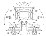
前記筒状隔壁20は、成膜ロール3の周りに数mmの間隙を空けて配置され、一端が後端壁12に、他端中央部が前端壁13の中央部に接合される。また、図3に示すように、大略円筒状であり、上側の左右に長さ方向に開口した第1、第2スリット31,32が、下部に長さ方向に開口した第3スリットが設けられ、また上部に基材を成膜ロール3へ巻き出し、巻き取るための巻出し巻取り用開口34、下側の左右に成膜部用開口35,35が開設されている。また、前記成膜部用開口35,35のカソード側に、図2に示すように、被覆成膜領域を開口部のみに制限するマスク36,36が付設される。
The
前記横隔壁21は、筒状隔壁20の上部に左右かつ上下二段に水平に延設された上下二段の左横隔壁22、22及び右横隔壁23、23とで構成される。前記左横隔壁22及び右横隔壁23は、その後端部が後端壁12に接合され、側端部の一方が前記筒状隔壁20の外周に接合され、他方が真空チャンバ1の胴部11側壁の内面に接合される。前記縦隔壁24,24は、前記筒状隔壁20の下部に並設され、一端が前記筒状隔壁20の外周面に接続され、他端が真空チャンバ1の胴部11の下壁内面に接合される。前記左横隔壁22の上下隔壁の間、前記右横隔壁23の上下隔壁の間及び縦隔壁24の左右隔壁の間にはそれぞれ第1,第2,第3圧力隔壁室26,27,28(これらをまとめて「圧力隔壁室」という場合がある。)が形成され、これらの圧力隔壁室は前記筒状隔壁20の第1スリット31、第2スリット32、第3スリット33及び成膜ロール3の側面と後端壁12内面および前端壁13内面との隙間を通して互いに連通している。このように、ロール室16、左右の成膜室17,17をそれぞれ前記圧力隔壁室にて分離することで、各室の雰囲気の独立性が高まり、成膜品質を向上させることができる。
The horizontal barrier rib 21 includes upper and lower left
前記ロール室16、左右の成膜室17,17及び第3圧力隔壁室28は、各々ターボ分子ポンプなどの真空ポンプ38の吸引口が開口しており、ロール室16、圧力隔壁室、各成膜室17,17の圧力、ガス雰囲気は独立に制御される。前記真空ポンプ38は後端壁12や胴部11側壁に付設され、それぞれ排気管39が連結され、これらは集合排気管40に連結されて図示省略した粗引き用真空ポンプに連通接続される。なお、図2において、排気管39や集合排気管40は図示省略されている。
The
前記真空チャンバ1は、分割構造とされ、中央部に配置された固定側チャンバ部1Fと、前記固定側チャンバ部1Fの左右に配置された移動側チャンバ部1M,1Mとで構成される。前記固定側チャンバ部1Fの内部には、前記成膜ロール3、巻出しロール6、巻取りロール7、補助ロールを備え、その後端壁にはこれらのロールの駆動装置(図示省略)、ロール室16及び圧力隔壁室用の真空ポンプ38が付設される。一方、移動側チャンバ部1M,1Mの前端壁内側には、カソードボックス4が取り付けられ、胴部側壁には成膜室用真空ポンプ38が付設される。また、前記筒状隔壁20の前端中央部及び前記ロール支持板14は、固定側チャンバ部1Fの前端壁に取り付けられる。なお、固定側チャンバ部1Fあるいは移動側チャンバ部1M,1Mにおける後端壁、前端壁、胴部は、真空チャンバ1の対応部材が分割された一部を意味する。
The
また、前記上下二段の左横隔壁22,22及び右横隔壁23,23もそれぞれ分割構造とされ、前記固定側チャンバ部1Fに配置された上下二段の固定側左横隔壁部22F,22F及び固定側右横隔壁部23F,23Fと、左右の移動側チャンバ部1M、1Mに配置された移動側左横隔壁22M,22M及び移動側右横隔壁部23M,23Mとで構成される(図4参照)。
Further, the upper and lower two-stage left
前記固定側チャンバ部1Fと移動側チャンバ部1M,1M、並びに固定側左横隔壁部22F,22Fと移動側左横隔壁部22M,22M、固定側右横隔壁部23F,23Fと移動側右横隔壁部23M,23Mとは、前記真空チャンバ1の後端壁12の左右の側端と胴部11の後端側の左右の側端の交叉部と、前端壁13の幅中心から左右に壁幅の1/8〜1/4程度離れた部位で、前端壁13の上端及び下端を通る二つの分割平面D,Dによって前記真空チャンバ1並びに左横隔壁22,22及び右横隔壁23,23が分割されたものである。前記分割平面Dは、図例では胴部11の後端側の側端と後端壁12の側端との交叉部を通るようにしたが、後端壁12の側端付近あるいは胴部11の後端壁12側の側端付近を通るようにしてもよく、要は巻出しロール6あるいは巻取りロール7のボビン交換に支障がない部位で胴部11あるいは後端壁12が分割されればよい。
The fixed
前記移動側チャンバ部1M,1Mは、固定側チャンバ部1Fの前端壁の外面に設けられたヒンジ機構、すなわち回動軸42および支持金具43によって固定側チャンバ部1Fに対して開閉自在とされている。そして、前記移動側チャンバ部1Mを固定側チャンバ部1F側に回動させることにより、前記固定側チャンバ部1Fと移動側チャンバ部1Mの分割端部、並びに前記固定側左横隔壁部22F,22Fと移動側左横隔壁部22M,22M、前記固定側右横隔壁部23F,23Fと移動側右横隔壁部23M,23Mの分割端部、筒状隔壁20の前端の左右露出部と移動側チャンバ部1M,1Mの前端壁内面をそれぞれシール材(図示省略)を介して相互に当接させる。これによって、当接部はそれぞれ気密に連結される。
また、移動側チャンバ部1Mが固定側チャンバ部1Fに当接し、気密に一体化した状態から、移動側チャンバ部1Mを固定チャンバ部1Fから離反するように回動させることにより、移動側チャンバ部1Mは固定側チャンバ部1Fから離反して分離され、固定側チャンバ部1Fの両側が解放される。
また、成膜室用の真空ポンプ38の排気管39も、真空チャンバ1の分割面に沿ってシール材を介して当接離反自在に分割され、移動側チャンバ部1Mの開閉により気密に連結分離される。
なお、各分割端部(当接離反部)には、必要に応じて当接幅を広くするフランジ部を形成し、これにシール材を付設するようにしてもよい。もっとも、真空チャンバ1の分割端面は、前端壁13や胴部11の側壁を形成する壁材自体が数十mmの厚さがあるので、前記フランジ部を設けるには及ばない。また、本発明では分割端部同士は当接離反し、摺動することがないので、分割端部に付設されるシール材は、従来のような隔壁端部と係合する凹部は不要であり、断面形状が丸形や角形などの単純形状のもので十分である。
The moving-
Further, the moving
Further, the
It should be noted that a flange portion that increases the contact width may be formed on each divided end portion (contact / separation portion) as necessary, and a sealing material may be attached thereto. However, since the wall material itself which forms the side wall of the
この連続成膜装置の動作、操作について説明する。
前記移動側チャンバ部1M,1Mを固定側チャンバ部1Fに連結一体化して真空チャンバ1を構成した状態において、巻出しロール6に装着されたボビンに巻き取られた未処理の帯状フィルムは、巻出しロール6の回転によってボビンから巻き出され、フリーロール8A、張力検出ロール9A、フリーリール10Aを介して、筒状隔壁20の上部に開設された巻出し巻取り用開口34から成膜ロール3に巻き掛けられ、成膜ロール3の回転によって連続的にボビンより巻き出され、成膜ロール3の外周上で成膜された後、前記巻出し巻取り用開口34からフリーロール10B、張力検出ロール9B、フリーロール8Bを介して巻取りロール7に装着されたボビンに巻き取られる。前記成膜ロール3の外周に設けられた筒状隔壁20には、左右の成膜室17,17に開口するように成膜部用開口35,35が設けられており、アルゴンガスなどの所定の雰囲気とされた成膜室17に設けられたカソードボックス4に高電圧を印加することにより、カソードボックス4に保持されたターゲットの一部がマスク36を介して成膜ロール3の表面に保持された帯状フィルムの表面にスパッタリングされ、機能性薄膜が形成される。
The operation and operation of this continuous film forming apparatus will be described.
In the state in which the moving
前記巻取りロール7に装着されたボビンが成膜済みの帯状フィルムで満たされると、装置を一旦停止し、真空チャンバ内を大気圧に戻して、図4に示すように、左右の移動側チャンバ部1M,1Mを固定側チャンバ部1Fから離反させて分離し、固定側チャンバ部1Fの両側を解放する。そして、巻出しロール6、巻取りロール7のボビンの交換や通紙作業を行い、また必要に応じて、ターゲットの交換を行った後、再び移動側チャンバ部1M,1Mを固定側チャンバ部1Fに気密に連結一体化し、真空チャンバ内を真空排気した後、再び成膜を行う。また、移動側チャンバ部を解放することにより、上記の通常作業のほか、定期的あるいは必要に応じてロールの交換や、カソードのメンテナンス、チャンバ内の清掃等が行われる。
When the bobbin mounted on the take-
上記連続成膜装置では、設置スペースが少ない割には巻出しロール6、巻取りロール7、カソードボックス4の正面に広い作業スペースを取ることができる。また、移動側チャンバ部1Mと固定側チャンバ部1Fとは簡単なヒンジ機構で開閉自在とされるので、従来のように、大掛かりな走行装置は不要であり、装置構成が簡単化される。また、移動側チャンバ部1Mの開閉の際、移動側チャンバ部1Mと固定側チャンバ部1F、移動側横隔壁部22M,23Mと固定側横隔壁部22F,23Fの分割端部は、互いにシール材を介して当接離反し、摺動することがないので、分割端部に設けたシール材が摩耗し難く、成膜品質の劣化を防止することができる。
In the continuous film forming apparatus, a large work space can be provided in front of the unwinding
上記実施形態では、移動側チャンバ部1Mの開閉機構としてヒンジ機構を採用したが、これに限らず、図5に示すように、移動側チャンバ部1Mをシリンダ等を駆動源とする直線移動機構によって固定側チャンバ部1Fの前後方向に進退させるようにしてもよい。この場合、従来のように、カソードボックスを取り付けた前端壁ごと移動させる必要がないので、従来のように大掛かりな走行装置は不要であり、また従来に比して設置スペースも少なくて済む。
In the above embodiment, the hinge mechanism is adopted as the opening / closing mechanism of the moving
また、上記実施形態では、真空チャンバ1のみならず、上下二段の左横隔壁22,22、右横隔壁23,23も二つの分割平面D,Dに沿って分割した構造としたが、図6の第2実施形態に示すように、左横隔壁22,右横隔壁23は必ずしも分割構造にする必要はなく、一体物のままで固定側チャンバ部1Fの後端壁内面、筒状隔壁20の外側面に接合するようにしてもよい。この場合、移動側チャンバ部1Mの開閉に応じて、左横隔壁22,右横隔壁23の側端部及び前端部は、移動側チャンバ部1Mの胴部側壁の内面、前端壁13の内面とシール材を介して当接離反するようにすればよい。なお、第2実施形態において、第1実施形態と同様の構成は同符合が付されている。
図6の第2実施形態の場合においても、移動側チャンバ部1Mの開閉機構は、図例のヒンジ機構に限らず、図7に示すように、固定側チャンバ部1Fの前後方向に対して斜め方向に移動側チャンバ部1Mを直線的に移動させるようにしてもよく、これにより移動側チャンバ部1Mの内面に設けたシール材と、左横隔壁22,右横隔壁23の側端部及び前端部との摺動を防止することができる。
また、上記第1、第2実施形態では、移動側チャンバ部1Mのヒンジ機構を前端壁13側に設けたが、図8に示すように後端壁12側に設けてもよい。この場合、チャンバのメンテナンススペースは若干大きくなるが、チャンバ内部のメンテナンス作業性はより向上する。
In the above embodiment, not only the
Also in the case of the second embodiment in FIG. 6, the opening / closing mechanism of the moving-
Moreover, in the said 1st, 2nd embodiment, although the hinge mechanism of the movement
また、本発明は上記実施形態のように真空チャンバ1が正面視方形に限らず、円形のものでもよく、また成膜室の個数も図例の2室に限らず、3室以上であってもよい。また、被成膜基材の走行経路も、図2のものに限らず、適宜の補助ロールを追加して任意の経路とすることができる。また、各室の区画には、前記実施形態のように圧力隔壁室を形成する必要はなく、単に隔壁によって区画してもよい。さらに、小型の連続成膜装置等の場合、ロール室と成膜室との間の隔壁を省略することもできる。
Further, in the present invention, the
また、上記実施形態は、隔壁(22,23,24)によって真空チャンバの内部を区画形成したものであるが、隔壁を有しないタイプの連続成膜装置に対しても、真空チャンバを上記のように移動側チャンバ部と固定側チャンバ部との分割構造とすることにより、メンテナンス性、作業性に優れ、従来のような大掛かりな移動装置を省略することができる。 In the above embodiment, the inside of the vacuum chamber is partitioned by the partition walls (22, 23, 24). However, the vacuum chamber is also used for a continuous film forming apparatus of a type having no partition wall as described above. In addition, the split structure of the moving side chamber portion and the fixed side chamber portion is excellent in maintainability and workability, and a conventional large moving device can be omitted.
1 真空チャンバ
1F 固定側チャンバ部
1M 移動側チャンバ部
3 成膜ロール
4 カソードボックス(成膜ユニット)
6 巻出しロール
7 巻取りロール
11 胴部
12 後端壁
13 前端壁
16 ロール室
17 成膜室
21 横隔壁
22 左横隔壁
23 右横隔壁
38 真空ポンプ
DESCRIPTION OF
6 Unwinding
Claims (5)
前記真空チャンバは、前記後端壁の左側の側端部あるいは前記胴部の後端左側の側端部と前記前端壁の上端及び下端を通る分割面及び前記後端壁の右側の側端部あるいは前記胴部の後端右側の側端部と前記前端壁の上端及び下端を通る分割面との二つの分割面によって左右の移動側チャンバ部とそれらの間に配置された固定側チャンバ部とに三分割され、
前記固定側チャンバ部の前端壁と後端壁とによって前記成膜ロール、巻出しロール及び巻取りロールが回転自在に支持され、前記移動側チャンバ部に前記成膜ユニットが備えられ、
前記左右の移動側チャンバ部と固定側チャンバ部の分割端部がシール材を介して当接離反するように前記左右の移動側チャンバ部を前記固定側チャンバ部に開閉するように設けた、連続成膜装置。 A hollow body, a vacuum chamber having a rear end wall and a front end wall respectively disposed at a rear end and a front end of the body, and housed in the vacuum chamber and driven to rotate from the rear end wall side A film forming roll, a film forming unit for forming a film on a film forming substrate housed in the vacuum chamber and wound around the film forming roll, and a film forming substrate housed in the vacuum chamber, A continuous film forming apparatus provided with an unwinding roll for supplying the film forming roll to the film forming roll and a winding roll for winding the film-forming substrate after film formation,
The vacuum chamber includes a left side end portion of the rear end wall or a left end side end portion of the body portion, a split surface passing through an upper end and a lower end of the front end wall, and a right side end portion of the rear end wall. Alternatively, the left and right moving-side chamber portions and the fixed-side chamber portion disposed between the left and right moving side chamber portions by two dividing surfaces, that is, a side end portion on the right side of the rear end of the body portion and a dividing surface passing through the upper end and the lower end of the front end wall Divided into three,
The film forming roll, the unwinding roll, and the winding roll are rotatably supported by the front end wall and the rear end wall of the fixed side chamber portion , and the moving side chamber portion includes the film forming unit,
Continuously provided to open and close the left and right moving side chamber portions to the fixed side chamber portion so that the divided end portions of the left and right moving side chamber portions and the fixed side chamber portion are in contact with and separated from each other via a sealant. Deposition device.
前記真空チャンバの内部は、前記巻出しロール及び巻取りロールが配置されたロール室と、前記成膜ユニットが配置された成膜室とが真空チャンバの内部に設けられた隔壁によって区画形成され、
前記真空チャンバは、前記後端壁の左側の側端部あるいは前記胴部の後端左側の側端部と前記前端壁の上端及び下端を通る分割面及び前記後端壁の右側の側端部あるいは前記胴部の後端右側の側端部と前記前端壁の上端及び下端を通る分割面との二つの分割面によって左右の移動側チャンバ部とそれらの間に配置された固定側チャンバ部とに三分割され、
前記隔壁は、前記二つの分割面によって前記固定側チャンバ部に配置された固定側隔壁部と、前記左右の移動側チャンバ部に配置された移動側隔壁部とに分割され、
前記固定側チャンバ部の前端壁と後端壁とによって前記成膜ロール、巻出しロール及び巻取りロールが回転自在に支持され、前記移動側チャンバ部に前記成膜ユニットが備えられ、
前記左右の移動側チャンバ部と固定側チャンバ部の分割端部並びに前記固定側隔壁部と移動側隔壁部の分割端部がそれぞれシール材を介して当接離反するように前記左右の移動側チャンバ部を固定側チャンバ部に対して開閉するように設けた、連続成膜装置。 A hollow body, a vacuum chamber having a rear end wall and a front end wall respectively disposed at a rear end and a front end of the body, and housed in the vacuum chamber and driven to rotate from the rear end wall side A film forming roll, a film forming unit for forming a film on a film forming substrate housed in the vacuum chamber and wound around the film forming roll, and a film forming substrate housed in the vacuum chamber, A continuous film forming apparatus provided with an unwinding roll for supplying the film forming roll to the film forming roll and a winding roll for winding the film-forming substrate after film formation,
The inside of the vacuum chamber is partitioned and formed by a partition provided inside the vacuum chamber, a roll chamber in which the unwinding roll and the take-up roll are arranged, and a film forming chamber in which the film forming unit is arranged,
The vacuum chamber includes a left side end portion of the rear end wall or a left end side end portion of the body portion, a split surface passing through an upper end and a lower end of the front end wall, and a right side end portion of the rear end wall. Alternatively, the left and right moving-side chamber portions and the fixed-side chamber portion disposed between the left and right moving side chamber portions by two dividing surfaces, that is, a side end portion on the right side of the rear end of the body portion and a dividing surface passing through the upper end and the lower end of the front end wall Divided into three,
The partition wall is divided into a fixed partition wall portion disposed in the fixed chamber portion by the two split surfaces, and a movable partition wall portion disposed in the left and right moving chamber portions,
The film forming roll, the unwinding roll, and the winding roll are rotatably supported by the front end wall and the rear end wall of the fixed side chamber portion , and the moving side chamber portion includes the film forming unit,
The left and right moving chambers are arranged such that the divided end portions of the left and right moving side chamber portions and the fixed side chamber portion and the divided end portions of the fixed side partition portion and the moving side partition portion are in contact with and separated from each other via a sealing material. A continuous film forming apparatus provided to open and close the part with respect to the fixed chamber part.
前記真空チャンバの内部は、前記巻出しロール及び巻取りロールが配置されたロール室と、前記成膜ユニットが配置された成膜室とが真空チャンバの内部に配置された隔壁によって区画形成され、
前記真空チャンバは、前記後端壁の左側の側端部あるいは前記胴部の後端左側の側端部と前記前端壁の上端及び下端を通る分割面及び前記後端壁の右側の側端部あるいは前記胴部の後端右側の側端部と前記前端壁の上端及び下端を通る分割面との二つの分割面によって左右の移動側チャンバ部とそれらの間に配置された固定側チャンバ部とに三分割され、
前記固定側チャンバ部の前端壁と後端壁とによって前記成膜ロール、巻出しロール及び巻取りロールが回転自在に支持され、前記移動側チャンバ部に前記成膜ユニットが備えられ、前記隔壁が前記固定側チャンバ部に設けられ、
前記左右の移動側チャンバ部と固定側チャンバ部の分割端部並びに前記移動側チャンバ部の内面と前記隔壁の端部がそれぞれシール材を介して当接離反するように前記左右の移動側チャンバ部を固定側チャンバ部に対して開閉するように設けた、連続成膜装置。 A hollow body, a vacuum chamber having a rear end wall and a front end wall respectively disposed at a rear end and a front end of the body, and housed in the vacuum chamber and driven to rotate from the rear end wall side A film forming roll, a film forming unit for forming a film on a film forming substrate housed in the vacuum chamber and wound around the film forming roll, and a film forming substrate housed in the vacuum chamber, A continuous film forming apparatus provided with an unwinding roll for supplying the film forming roll to the film forming roll and a winding roll for winding the film-forming substrate after film formation,
The inside of the vacuum chamber is partitioned and formed by a partition wall in which a roll chamber in which the unwinding roll and the take-up roll are arranged and a film forming chamber in which the film forming unit is arranged are arranged inside the vacuum chamber,
The vacuum chamber includes a left side end portion of the rear end wall or a left end side end portion of the body portion, a split surface passing through an upper end and a lower end of the front end wall, and a right side end portion of the rear end wall. Alternatively, the left and right moving-side chamber portions and the fixed-side chamber portion disposed between the left and right moving side chamber portions by two dividing surfaces, that is, a side end portion on the right side of the rear end of the body portion and a dividing surface passing through the upper end and the lower end of the front end wall Divided into three,
The film forming roll, the unwinding roll, and the winding roll are rotatably supported by the front end wall and the rear end wall of the fixed side chamber section, the film forming unit is provided in the moving side chamber section, and the partition wall includes Provided in the fixed-side chamber,
The left and right moving chamber portions are arranged so that the divided end portions of the left and right moving side chamber portions and the fixed side chamber portion, and the inner surface of the moving side chamber portion and the end portions of the partition walls are in contact with and separated from each other via a sealing material. Is a continuous film forming apparatus provided so as to be opened and closed with respect to the stationary chamber portion.
Priority Applications (2)
| Application Number | Priority Date | Filing Date | Title |
|---|---|---|---|
| JP2004261880A JP4421980B2 (en) | 2004-09-09 | 2004-09-09 | Continuous film deposition system |
| DE102005042762.6A DE102005042762B4 (en) | 2004-09-09 | 2005-09-08 | Apparatus for continuous coating |
Applications Claiming Priority (1)
| Application Number | Priority Date | Filing Date | Title |
|---|---|---|---|
| JP2004261880A JP4421980B2 (en) | 2004-09-09 | 2004-09-09 | Continuous film deposition system |
Publications (3)
| Publication Number | Publication Date |
|---|---|
| JP2006077284A JP2006077284A (en) | 2006-03-23 |
| JP2006077284A5 JP2006077284A5 (en) | 2006-10-05 |
| JP4421980B2 true JP4421980B2 (en) | 2010-02-24 |
Family
ID=36062337
Family Applications (1)
| Application Number | Title | Priority Date | Filing Date |
|---|---|---|---|
| JP2004261880A Expired - Fee Related JP4421980B2 (en) | 2004-09-09 | 2004-09-09 | Continuous film deposition system |
Country Status (2)
| Country | Link |
|---|---|
| JP (1) | JP4421980B2 (en) |
| DE (1) | DE102005042762B4 (en) |
Families Citing this family (14)
| Publication number | Priority date | Publication date | Assignee | Title |
|---|---|---|---|---|
| JP4573272B2 (en) * | 2006-07-26 | 2010-11-04 | 株式会社神戸製鋼所 | Continuous film deposition system |
| DE102007009615A1 (en) | 2007-02-26 | 2008-08-28 | Leybold Optics Gmbh | Vacuum coating apparatus for front surface of strip material has two process chambers containing process roller, connected by transfer chamber containing strip feed and strip winding rollers, rear surface of strip contacting all rollers |
| DE102008018396A1 (en) | 2008-04-10 | 2009-10-15 | Leybold Optics Gmbh | System for continuously vacuum-coating a band-shaped film, comprises vacuum chamber with a bottom side wall, covering wall, front wall, back wall, side walls and inner partition wall, stationary winding unit, and stationary coating roller |
| JP2010018828A (en) * | 2008-07-09 | 2010-01-28 | Asahi Kasei E-Materials Corp | Vacuum deposition apparatus |
| JP5241383B2 (en) | 2008-08-27 | 2013-07-17 | 株式会社神戸製鋼所 | Continuous film deposition system |
| JP5794519B2 (en) * | 2010-06-30 | 2015-10-14 | 国立大学法人富山大学 | Composite film forming apparatus and film forming method |
| DE102012104013A1 (en) | 2012-05-08 | 2013-11-14 | Schmid Vacuum Technology Gmbh | High vacuum system and method for evacuation |
| JP5969953B2 (en) * | 2013-05-31 | 2016-08-17 | 株式会社神戸製鋼所 | Deposition equipment |
| DE102013105824B4 (en) * | 2013-06-06 | 2017-07-13 | Von Ardenne Gmbh | Process arrangement and method for operating a process arrangement |
| JP6408949B2 (en) * | 2015-03-31 | 2018-10-17 | 株式会社神戸製鋼所 | Deposition equipment |
| JP2016191127A (en) * | 2015-03-31 | 2016-11-10 | 株式会社神戸製鋼所 | Partition wall structure and film-forming device having the same |
| CN110643969A (en) * | 2018-06-27 | 2020-01-03 | 北京铂阳顶荣光伏科技有限公司 | Vacuum evaporation equipment |
| DE102019007935B4 (en) | 2019-11-14 | 2023-06-29 | Elfolion Gmbh | Process for processing flexible substrates and vacuum processing system for implementing the process |
| CN113684462B (en) * | 2021-07-29 | 2023-07-21 | 苏州道一至诚纳米材料技术有限公司 | Double-sided reciprocating film plating device |
Family Cites Families (6)
| Publication number | Priority date | Publication date | Assignee | Title |
|---|---|---|---|---|
| DE4223568C1 (en) * | 1992-07-17 | 1993-11-18 | Leybold Ag | Aluminium@-zinc@ coating of foil esp. for capacitor - by vapour deposition while introducing oxygen@ |
| JPH1036967A (en) * | 1996-07-24 | 1998-02-10 | Teijin Ltd | Sputtering device |
| DE19832571A1 (en) * | 1998-07-20 | 2000-01-27 | Hauzer Ind Bv | Multi-layer coating and process for its production |
| JP2001003168A (en) * | 1999-06-18 | 2001-01-09 | Sony Corp | Vacuum film forming device |
| JP4568994B2 (en) * | 2000-12-04 | 2010-10-27 | 東洋紡績株式会社 | Roll coater type continuous sputtering equipment |
| JP2002339055A (en) * | 2001-03-15 | 2002-11-27 | Sony Corp | Thin film depositing apparatus |
-
2004
- 2004-09-09 JP JP2004261880A patent/JP4421980B2/en not_active Expired - Fee Related
-
2005
- 2005-09-08 DE DE102005042762.6A patent/DE102005042762B4/en active Active
Also Published As
| Publication number | Publication date |
|---|---|
| DE102005042762A1 (en) | 2006-04-06 |
| DE102005042762B4 (en) | 2016-10-20 |
| JP2006077284A (en) | 2006-03-23 |
Similar Documents
| Publication | Publication Date | Title |
|---|---|---|
| JP4421980B2 (en) | Continuous film deposition system | |
| JP2006077284A5 (en) | ||
| US8821638B2 (en) | Continuous deposition apparatus | |
| JP5240782B2 (en) | Continuous film deposition system | |
| WO2012086119A1 (en) | Take-up-type continuous film-forming apparatus | |
| US20150176118A1 (en) | Web substrate roll-forming apparatus and web substrate roll | |
| KR910004353A (en) | Retractable paper tow roller device for printing press | |
| US20100304155A1 (en) | Film deposition method, film deposition apparatus, and gas barrier film | |
| JP4221324B2 (en) | Band material coating apparatus having a vacuum chamber and a coating roller | |
| KR910005158B1 (en) | Apparatus for vacuum continuous treatment | |
| JP2005515299A (en) | Vacuum coating equipment for coating strip material | |
| JP4702801B2 (en) | Continuous film deposition system | |
| JPH11350136A (en) | Vacuum film forming device | |
| JP4573272B2 (en) | Continuous film deposition system | |
| JP2007509237A (en) | Band processing plant | |
| WO2021140888A1 (en) | Coating device, partition member, and coating method | |
| KR102143732B1 (en) | Automatic film winding device | |
| JP2001003168A (en) | Vacuum film forming device | |
| US20090032196A1 (en) | Arrangement for changing a winding drum | |
| JP2008031493A5 (en) | ||
| JP2020094276A (en) | Seal device, vacuum device, film deposition device, and film manufacturing method | |
| CN216639638U (en) | Film evaporation device | |
| JP2000178717A (en) | Film forming device | |
| CN113981408A (en) | Film evaporation device | |
| CN219930234U (en) | Vacuum evaporation device for manufacturing metallized film |
Legal Events
| Date | Code | Title | Description |
|---|---|---|---|
| A521 | Written amendment |
Free format text: JAPANESE INTERMEDIATE CODE: A523 Effective date: 20060822 |
|
| A621 | Written request for application examination |
Free format text: JAPANESE INTERMEDIATE CODE: A621 Effective date: 20060822 |
|
| A977 | Report on retrieval |
Free format text: JAPANESE INTERMEDIATE CODE: A971007 Effective date: 20090212 |
|
| A131 | Notification of reasons for refusal |
Free format text: JAPANESE INTERMEDIATE CODE: A131 Effective date: 20090224 |
|
| A521 | Written amendment |
Free format text: JAPANESE INTERMEDIATE CODE: A523 Effective date: 20090424 |
|
| A521 | Written amendment |
Free format text: JAPANESE INTERMEDIATE CODE: A523 Effective date: 20090428 |
|
| TRDD | Decision of grant or rejection written | ||
| A01 | Written decision to grant a patent or to grant a registration (utility model) |
Free format text: JAPANESE INTERMEDIATE CODE: A01 Effective date: 20091201 |
|
| A01 | Written decision to grant a patent or to grant a registration (utility model) |
Free format text: JAPANESE INTERMEDIATE CODE: A01 |
|
| A61 | First payment of annual fees (during grant procedure) |
Free format text: JAPANESE INTERMEDIATE CODE: A61 Effective date: 20091203 |
|
| FPAY | Renewal fee payment (event date is renewal date of database) |
Free format text: PAYMENT UNTIL: 20121211 Year of fee payment: 3 |
|
| R150 | Certificate of patent or registration of utility model |
Ref document number: 4421980 Country of ref document: JP Free format text: JAPANESE INTERMEDIATE CODE: R150 Free format text: JAPANESE INTERMEDIATE CODE: R150 |
|
| FPAY | Renewal fee payment (event date is renewal date of database) |
Free format text: PAYMENT UNTIL: 20131211 Year of fee payment: 4 |
|
| LAPS | Cancellation because of no payment of annual fees |