WO2014188950A1 - 画素補間装置およびその動作制御方法 - Google Patents
画素補間装置およびその動作制御方法 Download PDFInfo
- Publication number
- WO2014188950A1 WO2014188950A1 PCT/JP2014/062943 JP2014062943W WO2014188950A1 WO 2014188950 A1 WO2014188950 A1 WO 2014188950A1 JP 2014062943 W JP2014062943 W JP 2014062943W WO 2014188950 A1 WO2014188950 A1 WO 2014188950A1
- Authority
- WO
- WIPO (PCT)
- Prior art keywords
- pixel
- color
- pixels
- mixed
- same
- Prior art date
- Legal status (The legal status is an assumption and is not a legal conclusion. Google has not performed a legal analysis and makes no representation as to the accuracy of the status listed.)
- Ceased
Links
Images






























Classifications
-
- G—PHYSICS
- G06—COMPUTING OR CALCULATING; COUNTING
- G06T—IMAGE DATA PROCESSING OR GENERATION, IN GENERAL
- G06T3/00—Geometric image transformations in the plane of the image
- G06T3/40—Scaling of whole images or parts thereof, e.g. expanding or contracting
- G06T3/4015—Image demosaicing, e.g. colour filter arrays [CFA] or Bayer patterns
-
- H—ELECTRICITY
- H04—ELECTRIC COMMUNICATION TECHNIQUE
- H04N—PICTORIAL COMMUNICATION, e.g. TELEVISION
- H04N23/00—Cameras or camera modules comprising electronic image sensors; Control thereof
- H04N23/80—Camera processing pipelines; Components thereof
- H04N23/84—Camera processing pipelines; Components thereof for processing colour signals
- H04N23/843—Demosaicing, e.g. interpolating colour pixel values
-
- H—ELECTRICITY
- H04—ELECTRIC COMMUNICATION TECHNIQUE
- H04N—PICTORIAL COMMUNICATION, e.g. TELEVISION
- H04N23/00—Cameras or camera modules comprising electronic image sensors; Control thereof
- H04N23/80—Camera processing pipelines; Components thereof
- H04N23/84—Camera processing pipelines; Components thereof for processing colour signals
- H04N23/88—Camera processing pipelines; Components thereof for processing colour signals for colour balance, e.g. white-balance circuits or colour temperature control
-
- H—ELECTRICITY
- H04—ELECTRIC COMMUNICATION TECHNIQUE
- H04N—PICTORIAL COMMUNICATION, e.g. TELEVISION
- H04N25/00—Circuitry of solid-state image sensors [SSIS]; Control thereof
- H04N25/10—Circuitry of solid-state image sensors [SSIS]; Control thereof for transforming different wavelengths into image signals
- H04N25/11—Arrangement of colour filter arrays [CFA]; Filter mosaics
- H04N25/13—Arrangement of colour filter arrays [CFA]; Filter mosaics characterised by the spectral characteristics of the filter elements
- H04N25/134—Arrangement of colour filter arrays [CFA]; Filter mosaics characterised by the spectral characteristics of the filter elements based on three different wavelength filter elements
-
- H—ELECTRICITY
- H04—ELECTRIC COMMUNICATION TECHNIQUE
- H04N—PICTORIAL COMMUNICATION, e.g. TELEVISION
- H04N25/00—Circuitry of solid-state image sensors [SSIS]; Control thereof
- H04N25/40—Extracting pixel data from image sensors by controlling scanning circuits, e.g. by modifying the number of pixels sampled or to be sampled
- H04N25/46—Extracting pixel data from image sensors by controlling scanning circuits, e.g. by modifying the number of pixels sampled or to be sampled by combining or binning pixels
Definitions
- the present invention relates to a pixel interpolation device, its operation control method, and its operation control program.
- ⁇ Pixels may be mixed for each pixel of the same color to generate a reduced image.
- the pixel addition ratio is adjusted so that the centers of gravity of the addition pixels are evenly spaced (Patent Document 1).
- Patent Document 2 There is a technique in which the amplification amount before pixel addition is adjusted so that the centers of gravity of the addition pixels are equally spaced (Patent Document 2).
- This invention is intended to prevent the occurrence of false colors.
- the pixel interpolating device has a basic array pattern including a first color pixel, a second color pixel and a third color pixel each having a lower contribution rate to the luminance than the first color pixel.
- the first color pixel is the first type of first pixel present in the same row as at least the second color pixel or the third color pixel.
- the second color pixel and the third color pixel are mixed for each pixel of the same color for each pixel mixture pattern composed of a plurality of pixels in the row direction and the column direction.
- Multiple types of mixed pixels of the first color and mixed colors of the second color for each mixed pattern Same color pixel mixing means for obtaining mixed pixels of the pixel and the third color, and the color image is correlated with either the column direction or the row direction based on the plurality of kinds of first color mixed pixels obtained by the same color pixel mixing means.
- interpolating means for generating an interpolated pixel of the first color, an interpolated pixel of the second color, and an interpolated pixel of the third color for each pixel mixed pattern using the mixed pixels of the colors .
- the present invention also provides an operation control method suitable for a pixel interpolation device. That is, in this method, the same color pixel mixing means includes a first color pixel, a second color pixel, and a third color pixel, each having a lower contribution rate to the luminance than the first color pixel. In the color image in which the basic array pattern is repeated in the row direction and the column direction, the first color pixels are present in the same row as at least the second color pixels or the third color pixels.
- the second color pixel and the third color pixel are mixed for each pixel of the same color, and for each pixel mixture pattern composed of a plurality of pixels in the row direction and the column direction.
- a plurality of types of mixed pixels of the first color for each pixel mixture pattern, The mixed pixel of the first color and the mixed pixel of the third color are obtained, and the correlation discriminating unit is arranged in the column direction or the row in the color image based on the plurality of types of first color mixed pixels obtained by the same color pixel mixing unit.
- the interpolation means determines the mixed pixels of the first color and the second color of the plurality of types obtained by the same color pixel mixing means based on the determination result by the correlation determination means.
- a first color interpolation pixel, a second color interpolation pixel, and a third color interpolation pixel are generated for each pixel mixture pattern using the mixed pixel and the third color mixed pixel.
- the present invention also provides a program for executing the operation control method of the pixel interpolation device.
- a recording medium storing such a program may be provided.
- the first color pixel includes at least the first color pixel of the first type existing in the same row as the second color pixel or the third color pixel, and the second color pixel.
- a second color (different from the first type) first color pixel existing in the same column as the pixel or the third color pixel is mixed for each same color pixel, and the second color pixel and
- the mixing process is performed for each pixel mixture pattern for each pixel of the same color. Whether the color image has a correlation in the column direction or the row direction based on a plurality of types of first color mixed pixels and second color mixed pixels and third color mixed pixels obtained in pixel mixing Is determined.
- the first color interpolated pixel, the second color mixed pixel, the second color mixed pixel, and the third color mixed pixel are used for each pixel mixture pattern.
- Color interpolation pixels and third color interpolation pixels are generated.
- the interpolating unit for the second color pixel, is the first color pixel in the same row as the second color pixel.
- the third color pixel is less affected by the first color pixel in the same row as the third color pixel, and the correlation determination means correlates the row direction of the color image. Is determined, the second color pixel is less affected by the first color pixel in the same column as the second color pixel, and the third color pixel is the third color.
- the influence of the first color pixels in the same column as the first pixel is reduced, and a plurality of types of first color mixed pixels, second color mixed pixels and third color obtained in the same color pixel mixing means are obtained.
- the first color interpolation pixel, the second color interpolation pixel, and the third color for each pixel mixture pattern It may be generated interpolated pixel.
- the interpolating means outputs a second of the mixed pixels of the second color and the mixed pixels of the first color existing in the direction determined to be correlated by the correlation determining means among the plurality of kinds of mixed pixels of the first color.
- Difference data calculating means for calculating difference data for the third color may be provided.
- an average pixel of a plurality of types of first color mixed pixels is set as the first color interpolation pixel, and the difference between the first color interpolation pixel and the second color calculated by the difference data calculation unit is used.
- the pixel added with the data is set as the second color interpolation pixel, and the pixel obtained by adding the difference data for the third color calculated by the difference data calculation means to the first color interpolation pixel is set as the third color interpolation pixel. It would be a color interpolation pixel.
- the absolute value of the difference between the second color mixed pixel and the plurality of types of first color mixed pixels between the second color and the first color mixed pixel on the same column, and the third color mixed A first addition value obtained by adding the absolute value of the difference between the third color and the first color mixed pixel on the same column among the plurality of types of mixed pixels of the first color; , The absolute value of the difference between the second color mixed pixel and the first color mixed pixel on the same row among the plurality of types of first color mixed pixels, and the third color A second addition value obtained by adding the absolute value of the difference between the mixed pixel and the first color mixed pixel on the same row among the mixed pixels of the plurality of types of first colors And an addition value determining means for determining which is greater.
- the correlation determination means determines that there is a correlation in the column direction according to the addition value determination means determining that the first addition value is smaller than the second addition value. It will be determined that there is a correlation in the row direction when it is determined that the first added value is larger than the added value of.
- the basic array pattern is based on, for example, a Bayer array.
- a first color pixel having a green or magenta color component in the row direction and the column direction and a second color pixel having a red or cyan color component
- a third color pixel having a blue or yellow color component and at least one of the first color pixels is included in the column direction, the row direction, and the diagonal direction, and the column direction , At least one of two consecutive portions in the row direction and the oblique direction may be included.
- the color image includes pixels of the first color in the same row and column as the pixels of the second color, and pixels of the first color also in the same column and row as the third color pixels. Is something that exists.
- An imaging device provided with a pixel interpolation device may be provided.
- the state of pixel mixing is shown.
- the state of pixel mixing is shown.
- the state of pixel mixing is shown.
- the state of pixel mixing is shown.
- the state of pixel mixing is shown.
- the state of pixel mixing is shown.
- the state of pixel mixing is shown.
- the state of pixel mixing is shown.
- the state of pixel mixing is shown.
- the state of pixel mixing is shown.
- the state of pixel mixing is shown.
- the state of pixel mixing is shown.
- the state of pixel mixing is shown.
- the state of pixel mixing is shown.
- the state of pixel mixing is shown.
- the state of pixel mixing is shown.
- a partial color image of horizontal stripes is shown.
- a partial color image of vertical stripes is shown. 2 shows the electrical configuration of a digital camera.
- a partial color image It is an example of a partial color image.
- the state of pixel mixing is shown.
- the state of pixel mixing is shown.
- the state of pixel mixing is shown.
- the state of pixel mixing is shown.
- a partial color image of horizontal stripes is shown.
- a partial color image of vertical stripes is shown. It is an example of a partial color image.
- the state of pixel mixing is shown.
- the state of pixel mixing is shown.
- the state of pixel mixing is shown.
- the state of pixel mixing is shown.
- the state of pixel mixing is shown.
- the state of pixel mixing is shown.
- the state of pixel mixing is shown.
- a partial color image of horizontal stripes is shown.
- a partial color image of vertical stripes is shown.
- a partial color image of diagonal stripes is shown. It is an example of a partial color image.
- R pixels are shown.
- B pixels are shown.
- the G1 pixel is shown.
- the G2 pixel is shown.
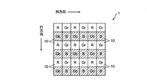
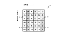
- FIG. 1 is a partial color image 1 showing a part of a color image obtained by an image sensor in which color filters are formed in a Bayer array on the light receiving surfaces of a large number of photodiodes.
- the partial color image 1 in FIG. 1 is composed of six pixels 10 in both the row direction (the direction in which the number of rows increases) and the column direction (the direction in which the number of columns increase).
- red pixels R pixels, second pixels
- Color pixels In the odd-numbered columns and odd-numbered rows, red pixels (R pixels, second pixels) obtained from the signal charges accumulated in the photodiode in which the red filter having the characteristic of transmitting the red light component is formed on the light receiving surface.
- Color pixels In the even-numbered column and the even-numbered row, a blue pixel (B pixel, third color) obtained from a signal charge accumulated in a photodiode in which a blue filter having a characteristic of transmitting a blue light component on the light receiving surface is formed. Pixels).
- green pixels obtained from signal charges accumulated in photodiodes having a green filter having a characteristic of transmitting a green light component on the light receiving surface are formed.
- Color pixels a green pixel between R pixels in an odd row is called a Gr pixel (first-type first color pixel), and a green pixel between B pixels in an even row is a Gb pixel (first pixel).
- R pixels may be arranged in odd rows and even columns
- B pixels may be arranged in even rows and odd columns
- green pixels may be arranged in addition.
- Gb pixels exist in the same row as B pixels
- Gr pixels exist in the same column.
- Gr pixels exist in the same row as the R pixels, and Gb pixels exist in the same column.
- the pixels 10 are repeated according to the basic array pattern of 2 pixels ⁇ 2 pixels in the column direction and the row direction.
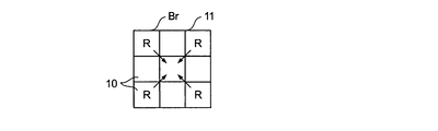
- a pixel mixed block Br (pixel mixed pattern) of 3 pixels ⁇ 3 pixels in the column direction and the row direction is defined.
- the same color pixels are mixed to reduce the color image to 1/9.
- the Gr pixel and the Gb pixel are the same color pixels, they are distinguished in the pixel mixture, and the Gr pixels and the Gb pixels are mixed.
- the pixel mixture block Br does not have to have a size of 3 pixels ⁇ 3 pixels.
- the upper left, the upper right, the lower left and the lower right image portions are represented as image portions 11, 12, 13 and 14
- FIG. 2 shows a pixel mixture of R pixels constituting the image portion 11.
- pixels other than the R pixel are omitted for easy understanding.
- the pixels 10 at the four corners are R pixels.
- Four R pixels at the four corners are mixed, and the averaged pixel becomes an R mixed pixel (mixed pixel of the second color) after the reduction of the image portion 11.
- FIG. 3 shows a pixel mixture of Gr pixels constituting the image portion 11.
- reference numerals representing the colors of pixels other than the Gr pixel are omitted.
- the upper and lower sides of the central pixel 10 are Gr pixels. These two Gr pixels are mixed, and the averaged pixel becomes a Gr mixed pixel (mixed pixel of the first color) after the reduction of the image portion 11.
- FIG. 4 shows a pixel mixture of Gb pixels constituting the image portion 11.
- reference numerals representing the colors of pixels other than Gb pixels are omitted.
- the left and right of the center pixel are Gb pixels. These two Gb pixels are mixed, and the averaged pixel becomes a Gb mixed pixel after reduction of the image portion 11 (mixed pixel of the first color).
- FIG. 5 shows B pixels constituting the image portion 11. Since the image portion 11 has one B pixel at the center, the B pixel itself is a reduced B mixed pixel (mixed pixel of the third color). As described above, the barycentric positions of the mixed pixels of the respective colors after the pixel mixing of the green component pixel, the blue component pixel, and the red component pixel, which are the pixels of each color, are on the same pixel position in the pixel mixture block Br. The pixels are mixed so that Since pixel reduction and pixel interpolation are performed simultaneously by such pixel mixing, interpolation processing (also referred to as demosaicing processing) generally performed as separate processing can be omitted, and the processing circuit can be simplified. The processing speed can be increased.
- interpolation processing also referred to as demosaicing processing
- FIG. 6 shows a pixel mixture of R pixels in the image portion 12. Since there are R pixels above and below the central pixel 10, these two R pixels are mixed to generate an R mixed pixel.
- FIG. 7 is a pixel mixture of Gr pixels in the image portion 12. Since there are Gr pixels at the four corners, these four Gr pixels are mixed to generate a Gr mixed pixel.
- FIG. 8 shows Gb pixels in the image portion 12. There is a Gb pixel in the center, and the Gb pixel is a Gb mixed pixel.
- FIG. 9 shows the B pixel of the image portion 12. Since there are B pixels on the left and right of the central pixel 10, the two B pixels are mixed to generate a B mixed pixel.
- FIG. 10 shows a pixel mixture of R pixels in the image portion 13. There are R pixels on the left and right of the center pixel 10, and these two R pixels are mixed to generate an R mixed pixel.
- FIG. 11 shows Gr pixels in the image portion 13. Since the Gr pixel is in the center, the Gr pixel becomes a Gr mixed pixel.
- FIG. 12 shows a pixel mixture of Gb pixels in the image portion 13.
- the Gb pixels at the four corners of the image portion 13 are mixed to generate a Gb mixed pixel.
- FIG. 13 shows a pixel mixture of B pixels in the image portion 13.
- the B pixels above and below the center pixel of the image portion 13 are mixed to generate a B mixed pixel.
- FIG. 14 to FIG. 17 show how pixels are mixed in the image portion 14. In these cases as well, the pixels other than the pixels to be mixed are not shown in the same manner as described above.
- FIG. 14 shows the R pixel of the image portion 14. Since the R pixel is in the center, the R pixel becomes an R mixed pixel.
- FIG. 15 shows Gr pixels of the image portion 14. Since the Gr pixels are on the left and right of the center pixel 10, the two Gr pixels are mixed to form a Gr mixed pixel.
- FIG. 16 shows the B pixel of the image portion 14. Since the B pixels are at the four corners, the four B pixels are mixed to form a B mixed pixel.
- FIG. 18 shows a partial color image 1 with horizontal stripes.
- the subject is a black and white horizontal stripe, and the period of white and black is equal to the interval at which the photodiode of the image sensor is formed. Then, as shown in FIG. 18, odd lines (or even lines) become white lines, and even lines (or odd lines) become black lines.
- the partial color image 1 is hatched so that it can be seen that it is a black line. The part not hatched represents a white line.
- the white level is 100 and the black level to 0.
- the level of the R mixed pixel is 100.
- the level of the Gr mixed pixel is also 100.
- the Gb pixel and the B pixel are each black, the levels of the Gb mixed pixel and the B mixed pixel are both 0.
- the Gr mixed pixel and the Gb mixed pixel are obtained from the same color filter characteristics, when they are mixed, the level of the G pixel after mixing becomes 50, and the reduced image after the pixel mixing is displayed. Will cause false colors. The same applies to portions other than the image portion 11.
- FIG. 19 shows a partial color image 1 with vertical stripes.
- the subject is a black and white vertical stripe, and the period of white and black is equal to the interval at which the photodiodes of the image sensor are formed. Then, as shown in FIG. 19, odd columns (or even columns) are white lines, and even columns (or odd columns) are black lines. Also in FIG. 18, hatching is added so that it can be seen that the color is black. The part not hatched is white.
- the white level is 100 and the black level is 0.
- the level of the R mixed pixel is 100.
- the level of the Gr mixed pixel is zero.
- the Gb pixel represents white as shown in FIG. 4, the level of the Gb mixed pixel is 100.
- the B pixel is black, the levels of the B mixed pixels are all zero.
- correlation direction determination is performed using an R mixed pixel, a Gr mixed pixel, a Gb mixed pixel, and a B mixed pixel obtained by pixel mixing.
- Expression 1 it is determined that the partial color image 1 has a correlation in the horizontal direction (column direction) as shown by the horizontal stripes in FIG. If Expression 1 is not satisfied, it is determined that the partial color image 1 has a correlation in the vertical direction (row direction) as shown by vertical stripes in FIG.
- the left side of the inequality sign in Equation 1 is the difference value of the mixed pixels generated from the pixels in the same row
- the left side of the inequality sign in Equation 1 is the difference value of the mixed pixels generated from the pixels in the same column.
- the fact that 1 is satisfied is because the level difference between pixels in the same row is small and it is considered that there is a correlation in the horizontal direction.
- Expression 1 does not hold is because the level difference between pixels in the same column is small and it is considered that there is a correlation in the vertical direction.
- the mixed pixel is corrected according to the correlation direction.
- an R pixel difference value Rsub and a B pixel difference value Bsub are respectively calculated.
- the R pixel difference value Rsub and the B pixel difference value Bsub are expressed by Expression 3 and Expression 4, respectively.
- the influence of the Gr pixel in the same row as the R pixel and the influence of the Gb pixel in the same row as the B pixel are reduced.
- R pixel difference value Rsub R mixed pixel ⁇ Gr mixed pixel Equation 3
- B pixel difference value Bsub B mixed pixel ⁇ Gb mixed pixel Equation 4
- the R pixel difference value Rsub and the B pixel difference value Bsub are expressed by Expression 5 and Expression 6, respectively.
- the influence of the Gb pixel in the same column as the R pixel and the influence of the Gr pixel in the same column as the B pixel are reduced.
- R pixel difference value Rsub R mixed pixel ⁇ Gb mixed pixel Equation 5
- B pixel difference value Bsub B mixed pixel ⁇ Gr mixed pixel Equation 6
- Interpolated pixels are generated from the mixed pixels obtained as described above as follows.
- G interpolation pixel (Gr mixed pixel + Gb mixed pixel) / 2 Equation 7
- R interpolation pixel G interpolation pixel + R pixel difference value
- B interpolation pixel G interpolation pixel + B pixel difference value
- FIG. 20 is a block diagram showing an electrical configuration of a digital camera that performs the above-described reduction and interpolation processing.
- the image sensor 20 has the above-described Bayer array, and outputs color image data (RAW data) representing a color image including the partial color image 1 as described above.
- the color image data output from the image sensor 20 is given to the correlation information calculation circuit 22 that constitutes the pixel interpolation device 21.
- the correlation information calculation circuit 22 pixel mixing is performed as described above, and an R mixture pixel, a B mixture pixel, a Gr mixture pixel, and a Gb mixture pixel are generated. Correlation information indicating the correlation direction of the color image is calculated from Equation 1 using these mixed pixels.
- RGB pixel interpolation circuit 23 From the correlation information calculation circuit 22, data representing R mixed pixels, B mixed pixels, Gr mixed pixels and Gb mixed pixels and data representing correlation information are output and supplied to the RGB pixel interpolation circuit 23.
- pixel difference values represented by Expression 3 and Expression 4 or Expression 5 and Expression 6 are calculated according to the correlation direction, and an interpolation pixel is generated based on Expression 7 to Expression 9. .
- the generated data representing the interpolated pixels is given to the display processing device 25 via the memory 24.
- the display processing device 25 When the display device 26 is controlled by the display processing device 25, the reduced image subjected to the interpolation processing is displayed. Needless to say, the display of the image displayed on the display device 26 prevents false colors.
- Pixel mixing is performed in the correlation information calculation circuit 22 to generate an R mixed pixel, a B mixed pixel, a Gr mixed pixel, and a Gb mixed pixel.
- Pixel mixing may be performed at the stage of reading out or outputting the image data. Thereby, the processing speed can be improved.
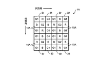
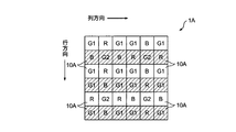
- FIG. 21 corresponds to FIG. 1, and is a partial color image 1A showing a part of a color image obtained by an image sensor formed in a predetermined arrangement on the light receiving surfaces of a large number of photodiodes.
- the partial color image 1A in FIG. 21 is also composed of six pixels 10A in both the row direction and the column direction.
- the red pixel, the green pixel, and the blue pixel are denoted by R, G, or B, respectively.
- the center G pixel G and the four corner G pixels G are distinguished in the pixel mixture block Br.
- the G pixels at the four corners are G1 pixels, and the center G pixel is the G2 pixel.
- the image portions 31 and 34 defined by the pixel mixture block Br at the upper left and lower right of the image portion 1A there are R pixels above and below the central G2 pixel, and there are B pixels on the left and right of the central G2 pixel. .
- the color image is repeated with the partial color image 1A shown in FIG. 21 as a basic array pattern.
- the partial color image 1A there are at least one G1 pixel, G2 pixel, R pixel, and B pixel in the horizontal direction (column direction) and the vertical direction (row direction), and the partial color image 1A is repeatedly arranged.
- at least one G1 pixel or G2 pixel exists in any horizontal direction, vertical direction, and diagonal direction of the color image.
- the partial color image 1A includes at least one portion where two G1 pixels or G2 pixels are continuous in the horizontal direction, the vertical direction, and the oblique direction. Further, the partial color image 1A includes at least one portion where two G1 pixels are continuous in the horizontal direction and the vertical direction.
- the G1 pixel is in the 6n (m is a positive integer) +1 row in the 6n (n is a positive integer) +1 row, the 6n + 3 row, the 6n + 4 row, and the 6n + 6 row.
- 6m + 3 rows, 6m + 4 rows and 6m + 6 rows are formed.
- the G2 pixels are formed in the sixth m + 2 column and the sixth m + 5 column in the sixth n + 2 row and the sixth n + 5 row.
- the B pixel B is in the sixth m + 5 column in the sixth n + 1 row and the sixth n + 3 row, in the sixth m + 1 column and the sixth m + 3 column in the sixth n + 2 row, in the sixth m + 2 column in the sixth n + 4 row and the sixth n + 6 row, and in the sixth n + 5 row. Then, it exists in the 6m + 4th column and the 6th + 6th column, respectively.
- the R pixel is in the sixth m + 2 column in the sixth n + 1 row, in the sixth m + 4 column and the sixth m + 6 column in the sixth n + 2 row, in the sixth m + 5 column in the sixth n + 4 row and the sixth n + 6 row, in the sixth m + 1 column and the sixth m + 3 column in the sixth n + 5 row.
- a color image is obtained by forming a red filter, a green filter or a blue filter on the light receiving surface of the photodiode of the photoelectric conversion element, but the light component of cyan C which is a complementary color of the three primary colors is transmitted.
- a cyan filter having characteristics, a magenta filter having characteristics that transmit the light component of magenta M, or a yellow filter having characteristics that transmit the light component of yellow Y are formed on the light receiving surface of the photodiode of the photoelectric conversion element.
- FIG. 22 shows a pixel mixture of R pixels. For ease of understanding, pixels other than the R pixel are omitted.
- the upper and lower pixels of the center pixel 10A are R pixels. These two R pixels are mixed, and the averaged pixel becomes the R mixed pixel after the image portion 31 is reduced.
- FIG. 23 shows a pixel mixture of G1 pixels constituting the image portion 31. Also in FIG. 23, reference numerals representing the colors of pixels other than the G1 pixel are omitted.
- the four corners are G1 pixels. These four G1 pixels are mixed, and the averaged pixel becomes the G1 mixed pixel after the image portion 31 is reduced.
- FIG. 24 shows a pixel mixture of G2 pixels constituting the image portion 31.
- the symbols representing the colors of the pixels other than the G2 pixel are omitted for easy understanding.
- the center pixel is a G2 pixel. This G2 pixel is used as the G2 mixed pixel after the image portion 31 is reduced.
- FIG. 25 shows B pixels constituting the image portion 31. The sign of the color of pixels other than the B pixel is omitted.
- B pixels on the left and right of the center pixel 10A There are B pixels on the left and right of the center pixel 10A. These two B pixels are mixed and averaged to become a reduced B mixed pixel.
- FIG. 26 and FIG. 27 show the state of pixel mixing in the image portion 32.
- the pixel mixture of the G1 pixels is the same as that shown in FIG. This is the same as that shown in FIG.
- FIG. 26 shows a pixel mixture of R pixels. Since there are R pixels on the left and right of the central pixel 10A, these two R pixels are mixed to generate an R mixed pixel. Needless to say, they are averaged.
- FIG. 27 shows a pixel mixture of B pixels. Since there are B pixels above and below the central pixel 10A, these two B pixels are mixed to generate a B mixed pixel. In this way, pixel mixing is performed so that the barycentric positions of the mixed pixels of each color after mixing the respective pixels of the green component, the blue component pixel, and the red component pixel are the same pixel position. is doing. Since pixel reduction and pixel interpolation are performed simultaneously by such pixel mixing, interpolation processing (also referred to as demosaicing processing) generally performed as separate processing can be omitted, and the processing circuit can be simplified. The processing speed can be increased.
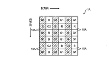
- FIG. 28 corresponds to FIG. 18 and shows a partial color image 1A with horizontal stripes.
- the subject has horizontal stripes and the period of white and black is equal to the interval at which the photodiodes of the image sensor are formed. Then, as shown in FIG. 28, odd lines (or even lines) become white lines, and even lines (or odd lines) become black lines.
- the partial color image 1A is hatched so that it can be seen that it is a black line. The part not hatched represents a white line.
- FIG. 29 shows a vertically striped partial color image 1A.
- the R mixed pixel, G1 mixed pixel, and G2 mixed obtained by pixel mixing are used.
- the correlation direction is determined using the pixel and the B mixed pixel.
- the correlation direction is determined using Expression 10A in which the R mixed pixel and the B mixed pixel are reversed in Expression 10.
- Expression 10A it is determined that the image portions 32 and 33 are correlated in the horizontal direction as shown in FIG. 28. If Expression 10A is not satisfied, the image portions 32 and 33 are the vertical stripes shown in FIG. Thus, it is determined that there is a correlation in the vertical direction.
- the sum of the absolute difference between the R mixed pixel and the G mixed pixel mixed on the same column and the absolute difference between the B mixed pixel and the G mixed pixel mixed on the same column is the same row.
- the correlation in the column direction is based on the comparison between the absolute value of the difference between the R mixed pixel and the G mixed pixel mixed in step B and the sum of the absolute difference between the B mixed pixel and the G mixed pixel mixed in the same row. It is judged whether there is a correlation in the row direction.
- the mixed pixel is corrected according to the correlation direction.
- an R pixel difference value Rsub and a B pixel difference value Bsub are respectively calculated.
- the R pixel difference value Rsub and the B pixel difference value Bsub are expressed by Expression 11 and Expression 12, respectively.
- the influence of the G1 pixel in the same row as the R pixel and the influence of the G2 pixel in the same row as the B pixel are reduced.
- R pixel difference value Rsub R mixed pixel ⁇ G1 mixed pixel Equation 11
- B pixel difference value Bsub B mixed pixel ⁇ G2 mixed pixel Equation 12
- the R pixel difference value Rsub and the B pixel difference value Bsub are expressed by Expression 13 and Expression 14, respectively.
- Expression 13 and Expression 14 As will be described later, when there is a correlation in the vertical direction, the influence of the G2 pixel in the same column as the R pixel and the influence of the G1 pixel in the same column as the B pixel are reduced.
- R pixel difference value Rsub R mixed pixel ⁇ G2 mixed pixel Equation 13
- B pixel difference value Bsub B mixed pixel ⁇ G1 mixed pixel Equation 14
- Interpolated pixels are generated from the mixed pixels obtained as described above as follows.
- G interpolation pixel (G1 mixed pixel + G2 mixed pixel) / 2 Equation 15
- R interpolation pixel G interpolation pixel + R pixel difference value
- B interpolation pixel G interpolation pixel + B pixel difference value
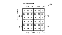
- FIG. 30 corresponds to FIG. 1 and FIG. 21, and is a partial color image 1A showing a part of a color image obtained by an image sensor formed in a predetermined arrangement on the light receiving surfaces of a number of photodiodes. is there.
- the partial color image 1B shown in FIG. 30 is also composed of six pixels 10B in both the row direction and the column direction.
- the red pixel, the green pixel, and the blue pixel are denoted by R, G, or B, respectively.
- any image portion 41 to 44 of the pixel mixture block Br of 3 pixels ⁇ 3 pixels there are G pixels at the center and at the top, bottom, left and right of the center. There are R pixels in the upper left and lower right of the center, and B pixels in the upper right and lower left of the center.
- the central G pixel, the upper and lower G pixels of the central G pixel, and the left and right G pixels of the central G pixel are distinguished.
- the upper and lower G pixels of the central G pixel are G1 pixels
- the left and right G pixels of the central G pixel are G2 pixels
- the central G pixel is a G3 pixel.
- the color image is repeated with the image portion 41 as a basic arrangement pattern.
- a color image is obtained by forming a red filter, a green filter or a blue filter on the light receiving surface of the photodiode of the photoelectric conversion element, but the light component of cyan C which is a complementary color of the three primary colors is transmitted.
- a cyan filter having characteristics, a magenta filter having characteristics that transmit the light component of magenta M, or a yellow filter having characteristics that transmit the light component of yellow Y are formed on the light receiving surface of the photodiode of the photoelectric conversion element.
- FIG. 31 to FIG. 35 show how pixels are mixed in the image portion 41. The same applies to the other image portions 42 to 44.
- FIG. 31 shows a pixel mixture of R pixels. For ease of understanding, pixels other than the R pixel are omitted.
- the upper left and lower right pixels of the center pixel 10B are R pixels. These two R pixels are mixed, and the averaged pixel becomes the R mixed pixel after the reduction of the image portion 41.
- FIG. 32 shows a pixel mixture of G1 pixels constituting the image portion 41. Also in FIG. 32, symbols representing the colors of pixels other than the G1 pixel are omitted.
- the top and bottom of the central pixel 10B are G1 pixels. These two G1 pixels are mixed, and the averaged pixel becomes the G1 mixed pixel after the image portion 41 is reduced.
- FIG. 33 shows a pixel mixture of G2 pixels constituting the image portion 41. Also in FIG. 33, symbols representing the colors of pixels other than the G2 pixel are omitted for the sake of clarity.
- the left and right of the center pixel 10B are G2 pixels. These G2 pixels are mixed and averaged to obtain a G2 mixed pixel after reduction of the image portion 41.
- FIG. 34 shows B pixels constituting the image portion 41. The sign of the color of pixels other than the B pixel is omitted.
- B pixels in the upper right and lower left of the center pixel 10B There are B pixels in the upper right and lower left of the center pixel 10B. These two B pixels are mixed and averaged to become a reduced B mixed pixel.
- FIG. 35 shows G3 pixels constituting the image portion 41.
- the G3 pixel at the center of the image portion 41 is a G3 mixed pixel.
- the pixels where the center of gravity of the mixed pixels of the respective colors after mixing the pixels of the green component, the blue component, and the red component, which are the pixels of each color, are on the same pixel position.
- interpolation processing also referred to as demosaicing processing
- the processing speed can be increased.
- FIG. 36 corresponds to FIGS. 18 and 28 and shows a partial color image 1B with horizontal stripes.
- the subject is a horizontal stripe and the period of white and black is equal to the interval at which the photodiodes of the image sensor are formed. Then, as shown in FIG. 36, odd lines (or even lines) become white lines, and even lines (or odd lines) become black lines.
- the partial color image 1B is hatched so that it can be seen that it is a black line. The part not hatched represents a white line.
- FIG. 37 shows a vertically striped partial color image 1B.
- FIG. 38 shows a partial color image 1B with diagonal stripes.
- the third absolute value When the absolute value of the difference from the pixel is the third absolute value, it is considered that there is a correlation of the image portion 41 in the direction that gives the smallest absolute value.
- the first absolute value, the second absolute value, or the third absolute value is the smallest, it is considered that there is a horizontal correlation, a vertical correlation, or a diagonal correlation.
- Equation 18 The R pixel difference value Rsub and the B pixel difference value Bsub when the correlation direction is the horizontal direction are expressed by Equation 18 and Equation 19.
- R pixel difference value Rsub R mixed pixel ⁇ G1 mixed pixel Equation 18
- B pixel difference value Bsub B mixed pixel ⁇ G1 mixed pixel Equation 19
- Equation 20 The R pixel difference value Rsub and the B pixel difference value Bsub when the correlation direction is the vertical direction are expressed by Equation 20 and Equation 21.
- R pixel difference value Rsub R mixed pixel ⁇ G2 mixed pixel Equation 20
- B pixel difference value Bsub B mixed pixel ⁇ G2 mixed pixel Equation 21
- Equation 22 The R pixel difference value Rsub and the B pixel difference value Bsub when the correlation direction is an oblique direction are expressed by Equation 22 and Equation 23.
- R pixel difference value Rsub R mixed pixel ⁇ G3 mixed pixel Equation 22
- B pixel difference value Bsub B mixed pixel ⁇ G3 mixed pixel Equation 23
- Interpolated pixels are generated from the mixed pixels obtained as described above. Needless to say, the R pixel difference value Rsub and the B pixel difference value Bsub are used corresponding to the correlation direction.
- G interpolation pixel (G1 mixed pixel + G2 mixed pixel + G3 mixed pixel) / 3 Equation 24
- R interpolation pixel G interpolation pixel + R pixel difference value
- B interpolation pixel G interpolation pixel + B pixel difference value Bsub Equation 26
- a reduced image is generated using the interpolation pixels obtained based on Expressions 24 to 26, so that the high-frequency horizontal stripes, vertical stripes, or diagonal stripes are generated as described above. Even a striped black and white image can be reduced and interpolated without generating false colors.
- FIG. 39 corresponds to FIG. 1, FIG. 21, and FIG. 30, and is a partial color showing a part of a color image obtained by an image sensor formed in a predetermined arrangement on the light receiving surfaces of a large number of photodiodes. Image 1C.
- the partial color image 1C shown in FIG. 39 is composed of three pixels 10C in both the row direction and the column direction.
- the red pixel, the green pixel, and the blue pixel are denoted by R, G, and B, respectively.
- R pixels are arranged in the 3n + 1 row, the 3n + 2 column, and the 3n + 2 row, the 3n + 3 column.
- B pixels are arranged in the 3n + 2 row, the 3n + 1 column, and the 3n + 3 row, the 3n + 2 column.
- G pixels are arranged at other locations. By repeating such a basic array pattern, a color image is formed.
- a color image is obtained by forming a red filter, a green filter or a blue filter on the light receiving surface of the photodiode of the photoelectric conversion element, but the light component of cyan C which is a complementary color of the three primary colors is transmitted.
- a cyan filter having characteristics, a magenta filter having characteristics that transmit the light component of magenta M, or a yellow filter having characteristics that transmit the light component of yellow Y are formed on the light receiving surface of the photodiode of the photoelectric conversion element.
- FIG. 40 is an example of a partial color image 1D configured by repeating the partial color image 1C shown in FIG. 39 in the row direction and the column direction.
- G1 pixels first type of first color pixels
- G2 pixels second type of first colors
- G pixels are arranged in the 6n + 4 rows and 6n + 4 columns.
- predetermined G pixels are defined as G1 pixels and G2 pixels. Only the B pixel exists in the same row of the G1 pixel, and the R pixel does not exist. In the same column of G1 pixels, there are only R pixels and no B pixels. Only the R pixel exists in the same row of the G2 pixels, and the B pixel does not exist. Only the B pixel exists and the R pixel does not exist in the same column of the G2 pixels.
- the pixel mixture block Br is composed of a total of 16 pixels, 4 pixels in each of the horizontal direction and the vertical direction defined by the 6n + 2 row to the 6n + 5 row and the 6n + 2 column to the 6n + 5 column.
- FIG. 41 shows R pixels constituting the image portion of the pixel mixture block Br. Also in FIG. 41, reference numerals representing the colors of pixels other than the R pixel are omitted. A plurality of R pixels are mixed and the averaged pixel becomes an R mixed pixel after reduction of the image portion of the pixel mixed block Br.
- FIG. 42 shows B pixels constituting the image portion of the pixel mixture block Br.
- symbols representing the colors of pixels other than the B pixel are omitted for the sake of clarity.
- a plurality of B pixels are mixed and the averaged pixel becomes the B mixed pixel after reduction of the pixel mixed block Br.
- FIG. 43 shows G1 pixels constituting the image portion of the pixel mixture block Br.
- the sign of the color of pixels other than the G1 pixel is omitted. Since there is one G1 pixel in the pixel mixture block Br, the G1 pixel becomes the G1 mixture pixel.
- FIG. 44 shows G2 pixels constituting the image portion of the pixel mixture block Br.
- the sign of the color of pixels other than the G2 pixel is omitted. Since the G2 pixel is also one in the pixel mixture block Br, the G2 pixel becomes the G2 mixture pixel.
- the correlation direction determination is performed using the R mixed pixel, the B mixed pixel, the G1 mixed pixel, and the G2 mixed pixel obtained by pixel mixing for each pixel mixed block Br.
- the above-described equation 10A can be used.
- Expression 10A holds, it is determined that the image portion of the pixel mixture block Br has a correlation in the horizontal direction. If Expression 10A does not hold, it is determined that the image portion of the pixel mixture block Br has a correlation in the vertical direction.
- the R pixel difference value Rsub described above is calculated from Equation 13
- the B pixel difference value Bsub is calculated from Equation 14. If it is determined that there is a correlation in the vertical direction, the R pixel difference value Rsub is calculated from Equation 11 and the B pixel difference value Bsub is calculated from Equation 12.
- the G interpolation pixels include eight G pixels (G1 and G2 pixels included in the pixel mixture block Br, and G pixels indicated by blank portions of the pixel mixture block Br shown in FIG. 40 and the like as described above. It is obtained from Equation 27 as an average value of However, the G interpolation pixel may be calculated from Equation 15.
- G interpolation pixel ⁇ G / 8 Equation 27
- the R interpolation pixel and the B interpolation pixel are obtained from Equation 16 and Equation 17, respectively.
- the pixel mixture block Br pixel mixture pattern
- G1 pixels first color pixels of the first type
- G2 pixels where R pixels (second color pixels) or B pixels (third color pixels) exist in the same column.
- the pixel mixture block Br pixel mixture pattern
- the pixel mixture block Br is set so that there are G2 pixels (second-type first color pixels) different from the G1 pixels. This is because, in a color image in which the basic array pattern is repeated in the horizontal and vertical directions, at least R pixels (second color pixels) or B pixels (third color pixels) exist only in the same row.
- the color image is correlated in either the column direction or the row direction. It is determined whether there is. Specifically, the mixed pixel of the first color pixel (G1 pixel or G2 pixel) existing in the same row as the second color pixel (R pixel), the second color mixed pixel, and the third color A first correlation that is a correlation with the mixed pixel of the first color, and a mixed pixel of the first color pixel (G2 pixel or G1 pixel) and the second color pixel (R pixel) in the same column as the second color pixel.
- the second correlation which is a correlation between the mixed pixel of the second color and the mixed pixel of the first color pixel (G1 pixel or G2 pixel) existing in the same column as the third color pixel (B pixel) Are compared, and it is determined whether the color image has a correlation in the column direction or the work direction.
- G1, G2 a mixed pixel of the second color
- B a third color
- an interpolation pixel of the first color (G), an interpolation pixel of the second color (R), and an interpolation pixel of the third color (B) are generated for each pixel mixture pattern.
- the color image is obtained by forming each color filter on the light receiving surface of the photodiode of the photoelectric conversion element.
- the present invention is not limited to this.
- a photoelectric conversion element using an organic substance or the like may be employed, and a color image may be obtained from an imaging element that performs photoelectric conversion on a specific color component of incident light in a photodiode.
- FIG. 45 is a block diagram showing the electrical configuration of the personal computer.
- the overall operation of the personal computer is controlled by the CPU 70.
- the CPU 70 is connected to a communication device 71, a memory 72, an input device 73 such as a keyboard, and a display device 74.
- the personal computer also includes a hard disk 78, a hard disk drive 77 for accessing the hard disk 78, and a CD-ROM (compact disk-read only memory) drive 75.
- ⁇ CD-ROM 76 storing a program for performing the above-described processing is loaded into the CD-ROM drive 75, and the program is read from the CD-ROM 76.
- the above-described processing is executed by installing the read program on the personal computer. Even if the program is not stored in the CD-ROM 76, the program transmitted via the network may be received by the communication device 71 and installed in the personal computer.
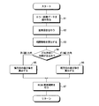
- FIG. 46 is a flowchart showing the processing procedure of the personal computer shown in FIG.
- the color image data captured by the image sensor is recorded on the hard disk 78, and the color image data is read from the hard disk 78 (step 81).
- the read color image data is subjected to the following processing for each pixel mixture block Br.
- pixels are mixed for each pixel of the same color (step 82).
- the Gr pixel, Gb pixel, G1 pixel, G2 pixel, and G3 pixel are pixel-mixed so as not to be mixed for each pixel.
- correlation information representing the correlation direction is calculated (step 87).
- the correlation information indicating the correlation direction is calculated based on Equation 1 and the like.
- step 84 Based on the correlation information, it is determined in which direction there is a correlation (step 84). If there is a correlation in the column direction (horizontal direction), as described above, the R pixel difference value Rsub and the B pixel difference value Bsub corresponding to the horizontal direction are calculated (step 85). If there is a correlation in the row direction (vertical direction), an R pixel difference value Rsub and a B pixel difference value Bsub corresponding to the vertical direction are calculated (step 86).
- Interpolated pixels are generated as described above using the calculated R pixel difference value Rsub and B pixel difference value Bsub (step 87).
- the digital camera and the personal computer have been described as the embodiments of the photographing apparatus according to the embodiment of the present invention.
- the configuration of the photographing apparatus is not limited to this.
- a built-in type or an external type PC camera or a portable terminal device having a photographing function as described below can be used.
- Examples of the portable terminal device that is an embodiment of the photographing device according to the embodiment of the present invention include a mobile phone, a smartphone, a PDA (Personal Digital Assistants), and a portable game machine.
- a smartphone will be described as an example, and will be described in detail with reference to the drawings.
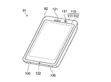
- FIG. 47 shows the appearance of a smartphone 91 which is an embodiment of the photographing apparatus of the present invention.
- a smartphone 91 shown in FIG. 47 includes a flat casing 92, and a display input in which a display panel 111 as a display unit and an operation panel 112 as an input unit are integrated on one surface of the casing 92.
- the unit 110 is provided.
- the casing 92 includes a microphone 122, a speaker 121, an operation unit 130, and a camera unit 131.
- the configuration of the housing 92 is not limited to this, and for example, a configuration in which the display unit and the input unit are independent, or a configuration having a folding structure or a slide mechanism may be employed.
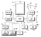
- FIG. 48 is a block diagram showing a configuration of the smartphone 91 shown in FIG.
- the main components of the smartphone include a wireless communication unit 100, a display input unit 110, a call unit 120, an operation unit 130, a camera unit 131, a storage unit 140, and an external input / output unit. 150, a GPS (Global Positioning System) receiving unit 160, a motion sensor unit 170, a power supply unit 180, and a main control unit 190.
- a wireless communication function for performing mobile wireless communication via the base station device BS and the mobile communication network NW is provided.
- the radio communication unit 100 performs radio communication with the base station apparatus BS accommodated in the mobile communication network NW in accordance with an instruction from the main control unit 190. Using such wireless communication, transmission / reception of various file data such as audio data and image data, e-mail data, and reception of Web data, streaming data, and the like are performed.
- the display input unit 110 displays images (still images and moving images), character information, etc., visually transmits information to the user, and detects user operations on the displayed information.
- a so-called touch panel which includes a display panel 111 and an operation panel 112.
- the display panel 111 uses an LCD (Liquid Crystal Display), OELD (Organic Electro-Luminescence Display) or the like as a display device.
- the operation panel 112 is a device that is placed so that an image displayed on the display surface of the display panel 111 is visible and detects one or more coordinates operated by a user's finger or stylus.
- a detection signal generated due to the operation is output to the main control unit 190.
- the main control unit 190 detects an operation position (coordinates) on the display panel 111 based on the received detection signal.
- the display panel 111 and the operation panel 112 of the smartphone 131 illustrated as an embodiment of the photographing apparatus of the present invention integrally constitute the display input unit 110.
- 112 is arranged so as to completely cover display panel 111.
- the operation panel 112 may have a function of detecting a user operation even in an area outside the display panel 111.
- the operation panel 112 has a detection area (hereinafter referred to as a display area) for an overlapping portion that overlaps the display panel 111 and a detection area (hereinafter, a non-display area) for an outer edge portion that does not overlap the other display panel 111. May be included).
- the operation panel 112 may be provided with two sensitive regions of the outer edge portion and the other inner portion. Furthermore, the width of the outer edge portion is appropriately designed according to the size of the housing 92 and the like. Furthermore, examples of the position detection method employed in the operation panel 112 include a matrix switch method, a resistive film method, a surface acoustic wave method, an infrared method, an electromagnetic induction method, and a capacitance method. You can also
- the call unit 120 includes a speaker 121 and a microphone 122, converts user's voice input through the microphone 122 into voice data that can be processed by the main control unit 190, and outputs the voice data to the main control unit 190. 100 or the audio data received by the external input / output unit 150 is decoded and output from the speaker 121. Also, as shown in FIG. 21, for example, the speaker 121 can be mounted on the same surface as the surface on which the display input unit 110 is provided, and the microphone 122 can be mounted on the side surface of the housing 92.
- the operation unit 130 is a hardware key using a key switch or the like, and receives an instruction from the user.
- the operation unit 130 is mounted on the side surface of the housing 92 of the smartphone 91 and is turned on when pressed with a finger or the like, and turned off when the finger is released with a restoring force such as a spring. It is a push button type switch.
- the storage unit 140 includes control programs and control data of the main control unit 190, application software, address data that associates names and telephone numbers of communication partners, transmitted and received e-mail data, Web data downloaded by Web browsing, Stores downloaded content data and temporarily stores streaming data and the like.
- the storage unit 140 includes an internal storage unit 141 built in the smartphone and an external storage unit 142 having a removable external memory slot.
- Each of the internal storage unit 141 and the external storage unit 142 constituting the storage unit 140 includes a flash memory type (flash memory type), a hard disk type (hard disk type), a multimedia card micro type (multimedia card micro type), It is realized using a storage medium such as a card type memory (for example, MicroSD (registered trademark) memory), a RAM (Random Access Memory), a ROM (Read Only Memory), or the like.
- flash memory type flash memory type
- hard disk type hard disk type
- multimedia card micro type multimedia card micro type
- a storage medium such as a card type memory (for example, MicroSD (registered trademark) memory), a RAM (Random Access Memory), a ROM (Read Only Memory), or the like.
- the external input / output unit 150 serves as an interface with all external devices connected to the smartphone 91, and communicates with other external devices (for example, universal serial bus (USB), IEEE 1394, etc.) or a network.
- external devices for example, universal serial bus (USB), IEEE 1394, etc.
- a network for example, the Internet, wireless LAN, Bluetooth (registered trademark), RFID (Radio Frequency Identification), infrared communication (IrDA) (registered trademark), UWB (Ultra Wideband) (registered trademark), ZigBee ( ZigBee) (registered trademark, etc.) for direct or indirect connection.
- Examples of the external device connected to the smartphone 91 include a memory card connected via a wired / wireless headset, wired / wireless external charger, wired / wireless data port, card socket, and SIM (Subscriber).
- Identity Module Card / UIM User Identity Module Card
- external audio / video equipment connected via audio / video I / O (Input / Output) terminal
- external audio video equipment connected wirelessly
- smartphones wired / wireless personal computers, wired / wireless connected PDAs, wired / wireless personal computers, earphones, and the like.
- the external input / output unit may transmit data received from such an external device to each internal component of the smartphone 1 or allow the internal data of the smartphone 1 to be transmitted to the external device. it can.
- the GPS receiving unit 160 receives GPS signals transmitted from the GPS satellites ST1 to STn in accordance with instructions from the main control unit 190, executes positioning calculation processing based on the received GPS signals, and calculates the latitude of the smartphone 91 Detects position consisting of, longitude and altitude.
- the GPS receiving unit 160 can acquire position information from the wireless communication unit 100 or the external input / output unit 150 (for example, a wireless LAN), it can also detect the position using the position information.
- the motion sensor unit 170 includes, for example, a three-axis acceleration sensor and detects the physical movement of the smartphone 91 in accordance with an instruction from the main control unit 190. By detecting the physical movement of the smartphone 91, the moving direction and acceleration of the smartphone 91 are detected. The detection result is output to the main control unit 190.
- the power supply unit 180 supplies power stored in a battery (not shown) to each unit of the smartphone 91 in accordance with an instruction from the main control unit 190.
- the main control unit 190 includes a microprocessor, operates according to a control program and control data stored in the storage unit 140, and controls each unit of the smartphone 91 in an integrated manner. Further, the main control unit 190 includes a mobile communication control function for controlling each part of the communication system and an application processing function in order to perform voice communication and data communication through the wireless communication unit 100.
- the application processing function is realized by the main control unit 190 operating according to the application software stored in the storage unit 140.
- Application processing functions include, for example, an infrared communication function for controlling external input / output unit 150 to perform data communication with an opposite device, an e-mail function for sending and receiving e-mails, and a web browsing function for browsing web pages. .
- the main control unit 170 also has an image processing function such as displaying video on the display input unit 110 based on image data (still image data or moving image data) such as received data or downloaded streaming data.
- the image processing function refers to a function in which the main control unit 190 decodes the image data, performs image processing on the decoding result, and displays an image on the display input unit 100.
- the main control unit 190 executes display control for the display panel 111 and operation detection control for detecting a user operation through the operation unit 130 and the operation panel 132.
- the main control unit 190 displays an icon for starting application software, a software key such as a scroll bar, or a window for creating an e-mail.
- a software key such as a scroll bar, or a window for creating an e-mail.
- the scroll bar refers to a software key for accepting an instruction to move an image display portion of a large image that cannot fit in the display area of the display panel 111.
- the main control unit 190 detects a user operation through the operation unit 130, or accepts an operation on the icon or an input of a character string in the input field of the window through the operation panel 112. Or a display image scroll request through a scroll bar is accepted.
- the main control unit 190 causes the operation position with respect to the operation panel 112 to overlap with the display panel 111 (display area) or other outer edge part (non-display area) that does not overlap with the display panel 111.
- a touch panel control function for controlling the sensitive area of the operation panel 112 and the display position of the software key.
- the main control unit 190 can also detect a gesture operation on the operation panel 112 and execute a preset function in accordance with the detected gesture operation.
- Gesture operation is not a conventional simple touch operation, but an operation that draws a trajectory with a finger, designates a plurality of positions at the same time, or combines these to draw a trajectory for at least one of a plurality of positions. means.
- the camera unit 131 is a digital camera that performs electronic photography using an image sensor such as a CMOS (Complementary Metal Oxide Semiconductor) or a CCD (Charge-Coupled Device).
- the camera unit 131 converts the image data obtained by imaging into compressed image data such as JPEG (Joint-Photographic-coding-Experts-Group) under the control of the main control unit 190, and records it in the storage unit 140, The data can be output through the output unit 150 or the wireless communication unit 100.
- the camera unit 131 is mounted on the same surface as the display input unit 110.
- the mounting position of the camera unit 131 is not limited to this, and the camera unit 131 may be mounted on the back surface of the display input unit 110. Alternatively, a plurality of camera units 131 may be mounted. When a plurality of camera units 131 are installed, the camera unit 131 used for shooting can be switched to perform shooting alone, or a plurality of camera units 131 can be used for shooting simultaneously.
- the camera unit 131 can be used for various functions of the smartphone 91.
- an image acquired by the camera unit 131 can be displayed on the display panel 111, and an image of the camera unit 131 can be used as one of operation inputs of the operation panel 112.
- the GPS receiving unit 160 detects the position
- the position can also be detected with reference to an image from the camera unit 131.
- the optical axis direction of the camera unit 131 of the smartphone 91 can be determined without using the triaxial acceleration sensor or in combination with the triaxial acceleration sensor. It is also possible to determine the current usage environment.
- the image from the camera unit 131 can also be used in the application software.
- the barycentric positions of the mixed pixels in the pixel mixed block Br are the same.
- Image sensor 21 pixel interpolator 22
- Correlation information calculation circuit 23 RGB pixel interpolation circuit Br Pixel mixing block
Landscapes
- Engineering & Computer Science (AREA)
- Multimedia (AREA)
- Signal Processing (AREA)
- Physics & Mathematics (AREA)
- Spectroscopy & Molecular Physics (AREA)
- General Physics & Mathematics (AREA)
- Theoretical Computer Science (AREA)
- Color Television Image Signal Generators (AREA)
- Transforming Light Signals Into Electric Signals (AREA)
Abstract
Description
B画素差分値Bsub=B混合画素-Gb混合画素・・・式4
B画素差分値Bsub=B混合画素-Gr混合画素・・・式6
R補間画素=G補間画素+R画素差分値Rsub・・・式8
B補間画素=G補間画素+B画素差分値Bsub・・・式9
B画素差分値Bsub=B混合画素-G2混合画素・・・式12
B画素差分値Bsub=B混合画素-G1混合画素・・・式14
R補間画素=G補間画素+R画素差分値Rsub・・・式16
B補間画素=G補間画素+B画素差分値Bsub・・・式17
B画素差分値Bsub=B混合画素-G1混合画素・・・式19
B画素差分値Bsub=B混合画素-G2混合画素・・・式21
B画素差分値Bsub=B混合画素-G3混合画素・・・式23
R補間画素=G補間画素+R画素差分値Rsub・・・式25
B補間画素=G補間画素+B画素差分値Bsub・・・式26
21 画素補間装置
22 相関情報算出回路
23 RGB画素補間回路
Br 画素混合ブロック
Claims (12)
- 第1の色の画素,第1の色の画素よりも輝度への寄与率がそれぞれ低い第2の色の画素および第3の色の画素を含む基本配列パターンが,行方向および列方向に繰り返されているカラー画像において,第1の色の画素については,少なくとも第2の色の画素または第3の色の画素と同一行に存在する第1種の第1の色の画素と,第2の色の画素または第3の色の画素と同一列に存在する上記第1種とは異なる第2種の第1の色の画素と,を分けて同色画素ごとに混合し,第2の色の画素および第3の色の画素については,同色画素ごとに混合する処理を,行方向および列方向に複数の画素から構成される画素混合パターンごとに行い,画素混合パターンごとに複数種類の第1の色の混合画素,第2の色の混合画素および第3の色の混合画素を得る同色画素混合手段,
上記同色画素混合手段によって得られた複数種類の第1の色の混合画素にもとづいて,カラー画像に列方向または行方向のどちらに相関があるかを判別する相関判別手段,ならびに
上記相関判別手段による判別結果にもとづいて,上記同色画素混合手段において得られた複数種類の第1の色の混合画素,第2の色の混合画素および第3の色の混合画素を用いて画素混合パターンごとに第1の色の補間画素,第2の色の補間画素および第3の色の補間画素を生成する補間手段,
を備えた画素補間装置。 - 上記補間手段は,
上記相関判別手段により,カラー画像の列方向に相関があると判断された場合には,第2の色の画素については第2の色の画素と同一行の第1の色の画素の影響を小さくし,第3の色の画素については第3の色の画素と同一行の第1の色の画素の影響を小さくし,
上記相関判別手段により,カラー画像の行方向に相関がある場合には,第2の色の画素については第2の色の画素と同一列の第1の色の画素の影響を小さくし,第3の色の画素については第3の色の画素と同一列の第1の色の画素の影響を小さくして,上記同色画素混合手段において得られた複数種類の第1の色の混合画素,第2の色の混合画素および第3の色の混合画素を用いて画素混合パターンごとに第1の色の補間画素,第2の色の補間画素および第3の色の補間画素を生成するものである,
請求項1に記載の画素補間装置。 - 上記補間手段は,
第2の色の混合画素と複数種類の第1の色の混合画素のうち上記相関判別手段により相関があると判定された方向に存在する第1の色の混合画素との第2の色についての差分データおよび第3の色の混合画素と複数種類の第1の色の混合画素のうち上記相関判別手段により相関があると判定された方向に存在する第1の色の混合画素との第3の色についての差分データを算出する差分データ算出手段を備え,
複数種類の第1の色の混合画素の平均画素を第1の色の補間画素とし,第1の色の補間画素に上記差分データ算出手段によって算出された第2の色についての差分データが加算された画素を第2の色の補間画素とし,第1の色の補間画素に上記差分データ算出手段によって算出された第3の色についての差分データが加算された画素を第3の色の補間画素とするものである,
請求項1または2に記載の画素補間装置。 - 第2の色の混合画素と複数種類の第1の色の混合画素のうち第2の色と同一列上の第1の色の混合画素との差分の絶対値と,第3の色の混合画素と複数種類の第1の色の混合画素のうち第3の色と同一列上の第1の色の混合画素との差分の絶対値と,を加算して得られる第1の加算値と,第2の色の混合画素と複数種類の第1の色の混合画素のうち第2の色と同一行上の第1の色の混合画素との差分の絶対値と,第3の色の混合画素と複数種類の第1の色の混合画素のうち第3の色と同一行上の第1の色の混合画素との差分の絶対値と,を加算して得られる第2の加算値と,のどちらが大きいかを判別する加算値判別手段をさらに備え,
上記相関判別手段は,
上記加算値判断手段により,第2の加算値よりも第1の加算値が小さいと判別されたことに応じて列方向に相関があると判別し,第2の加算値よりも第1の加算値が大きいと判別されたことに応じて行方向に相関があると判別するものである,
請求項1から3のうち,いずれか一項に記載の画素補間装置。 - 上記同色画素混合手段による第1の色の混合画素は2種類である,
請求項1から4のうち,いずれか一項に記載の画素補間装置。 - 上記同色画素混合手段において得られる複数種類の第1の色の混合画素,第2の色の混合画素および第3の色の混合画素の画素混合パターンにおける重心位置が同一である,
請求項1から5のうち,いずれか一項に記載の画素補間装置。 - 基本配列パターンはベイヤ配列にもとづくものである,
請求項1から6のうち,いずれか一項に記載の画素補間装置。 - 行方向および列方向の6×6の画素において,行方向および列方向において緑色またはマゼンタの色成分を有する第1の色の画素,赤色またはシアンの色成分を有する第2の色の画素および青色またはイエローの色成分を有する第3の色の画素が含まれており,第1の色の画素は,列方向,行方向および斜め方向において少なくとも一つは含まれており,かつ列方向,行方向および斜め方向において2つ連続している部分が少なくとも一つは含まれている,
請求項1から6のうち,いずれか一項に記載の画素補間装置。 - 上記カラー画像は,
第2の色の画素と同一行および同一列に第1の色の画素が存在し,かつ第3の色の画素と同一列および同一行にも第1の色の画素が存在しているものである,
請求項1から8のうち,いずれか一項に記載の画素補間装置。 - 請求項1から9のうち,いずれか一項に記載の画素補間装置を備えた撮像装置。
- 同色画素混合手段が,第1の色の画素,第1の色の画素よりも輝度への寄与率がそれぞれ低い第2の色の画素および第3の色の画素を含む基本配列パターンが,行方向および列方向に繰り返されているカラー画像において,第1の色の画素については,少なくとも第2の色の画素または第3の色の画素と同一行に存在する第1種の第1の色の画素と,第2の色の画素または第3の色の画素と同一列に存在する上記第1種とは異なる第2種の第1の色の画素と,を分けて同色画素ごとに混合し,第2の色の画素および第3の色の画素については,同色画素ごとに混合する処理を,行方向および列方向に複数の画素から構成される画素混合パターンごとに行い,画素混合パターンごとに複数種類の第1の色の混合画素,第2の色の混合画素および第3の色の混合画素を得,
相関判別手段が,上記同色画素混合手段によって得られた複数種類の第1の色の混合画素にもとづいて,カラー画像に列方向または行方向のどちらに相関があるかを判別し,
補間手段が,上記相関判別手段による判別結果にもとづいて,上記同色画素混合手段において得られた複数種類の第1の色の混合画素,第2の色の混合画素および第3の色の混合画素を用いて画素混合パターンごとに第1の色の補間画素,第2の色の補間画素および第3の色の補間画素を生成する,
画素補間装置の動作制御方法。 - 画素補間装置のコンピュータを制御するコンピュータが読み取り可能なプログラムであって,
第1の色の画素,第1の色の画素よりも輝度への寄与率がそれぞれ低い第2の色の画素および第3の色の画素を含む基本配列パターンが,行方向および列方向に繰り返されているカラー画像において,第1の色の画素については,少なくとも第2の色の画素または第3の色の画素と同一行に存在する第1種の第1の色の画素と,第2の色の画素または第3の色の画素と同一列に存在する上記第1種とは異なる第2種の第1の色の画素と,を分けて同色画素ごとに混合し,第2の色の画素および第3の色の画素については,同色画素ごとに混合する処理を,行方向および列方向に複数の画素から構成される画素混合パターンごとに行わせ,画素混合パターンごとに複数種類の第1の色の混合画素,第2の色の混合画素および第3の色の混合画素を得,
得られた複数種類の第1の色の混合画素にもとづいて,カラー画像に列方向または行方向のどちらに相関があるかを判別させ,
相関の判別結果にもとづいて,得られた複数種類の第1の色の混合画素,第2の色の混合画素および第3の色の混合画素を用いて画素混合パターンごとに第1の色の補間画素,第2の色の補間画素および第3の色の補間画素を生成させるように画素補間装置のコンピュータを制御するプログラム。
Priority Applications (3)
| Application Number | Priority Date | Filing Date | Title |
|---|---|---|---|
| JP2015518212A JP5877931B2 (ja) | 2013-05-23 | 2014-05-15 | 画素補間装置およびその動作制御方法 |
| CN201480029601.3A CN105264886B (zh) | 2013-05-23 | 2014-05-15 | 像素插值装置及其动作控制方法 |
| US14/947,916 US9727948B2 (en) | 2013-05-23 | 2015-11-20 | Pixel interpolation device and operation control method |
Applications Claiming Priority (2)
| Application Number | Priority Date | Filing Date | Title |
|---|---|---|---|
| JP2013108577 | 2013-05-23 | ||
| JP2013-108577 | 2013-05-23 |
Related Child Applications (1)
| Application Number | Title | Priority Date | Filing Date |
|---|---|---|---|
| US14/947,916 Continuation US9727948B2 (en) | 2013-05-23 | 2015-11-20 | Pixel interpolation device and operation control method |
Publications (1)
| Publication Number | Publication Date |
|---|---|
| WO2014188950A1 true WO2014188950A1 (ja) | 2014-11-27 |
Family
ID=51933509
Family Applications (1)
| Application Number | Title | Priority Date | Filing Date |
|---|---|---|---|
| PCT/JP2014/062943 Ceased WO2014188950A1 (ja) | 2013-05-23 | 2014-05-15 | 画素補間装置およびその動作制御方法 |
Country Status (4)
| Country | Link |
|---|---|
| US (1) | US9727948B2 (ja) |
| JP (1) | JP5877931B2 (ja) |
| CN (1) | CN105264886B (ja) |
| WO (1) | WO2014188950A1 (ja) |
Families Citing this family (4)
| Publication number | Priority date | Publication date | Assignee | Title |
|---|---|---|---|---|
| JP5865555B2 (ja) * | 2013-05-13 | 2016-02-17 | 富士フイルム株式会社 | 混色率算出装置及び方法並びに撮像装置 |
| JP6276580B2 (ja) * | 2013-12-20 | 2018-02-07 | 株式会社メガチップス | 画素補間処理装置、撮像装置、プログラムおよび集積回路 |
| JP6598507B2 (ja) * | 2015-05-11 | 2019-10-30 | キヤノン株式会社 | 撮像装置、撮像システム、信号処理方法 |
| US10366674B1 (en) | 2016-12-27 | 2019-07-30 | Facebook Technologies, Llc | Display calibration in electronic displays |
Citations (3)
| Publication number | Priority date | Publication date | Assignee | Title |
|---|---|---|---|---|
| JP2002010279A (ja) * | 2000-06-21 | 2002-01-11 | Nikon Corp | 補間処理装置および補間処理プログラムを記録した記録媒体 |
| JP2008098971A (ja) * | 2006-10-12 | 2008-04-24 | Matsushita Electric Ind Co Ltd | 固体撮像装置 |
| WO2012117584A1 (ja) * | 2011-02-28 | 2012-09-07 | 富士フイルム株式会社 | カラー撮像装置 |
Family Cites Families (13)
| Publication number | Priority date | Publication date | Assignee | Title |
|---|---|---|---|---|
| JP3389819B2 (ja) * | 1996-06-10 | 2003-03-24 | 株式会社村田製作所 | 誘電体導波管型共振器 |
| US6836572B2 (en) | 1998-06-01 | 2004-12-28 | Nikon Corporation | Interpolation processing apparatus and recording medium having interpolation processing program recorded therein |
| JP2003250091A (ja) * | 2002-02-22 | 2003-09-05 | Olympus Optical Co Ltd | 固体撮像素子の欠陥画素検出装置及び電子カメラ |
| JP2004356681A (ja) * | 2003-05-27 | 2004-12-16 | Olympus Corp | ホワイトバランス調整回路、その応用装置、ホワイトバランス調整方法、及びホワイトバランス調整プログラム |
| JP4826071B2 (ja) * | 2004-07-01 | 2011-11-30 | ソニー株式会社 | 物理情報取得方法および物理情報取得装置並びに物理量分布検知の半導体装置 |
| JP4759293B2 (ja) | 2005-03-15 | 2011-08-31 | キヤノン株式会社 | 撮像素子 |
| JP4752381B2 (ja) * | 2005-08-02 | 2011-08-17 | コニカミノルタオプト株式会社 | 撮像装置 |
| JP5183880B2 (ja) * | 2006-03-14 | 2013-04-17 | ソニー株式会社 | カラーフィルタおよび撮像素子 |
| JP4497233B2 (ja) * | 2007-07-30 | 2010-07-07 | カシオ計算機株式会社 | 画素補間回路、およびプログラム |
| JP5672776B2 (ja) * | 2010-06-02 | 2015-02-18 | ソニー株式会社 | 画像処理装置、および画像処理方法、並びにプログラム |
| CN103270757B (zh) * | 2011-03-11 | 2015-07-22 | 富士胶片株式会社 | 图像传感装置和控制其操作的方法 |
| EP2645723B1 (en) * | 2011-03-11 | 2015-06-17 | FUJIFILM Corporation | Imaging device, method for controlling operation thereof, and imaging system |
| US9007488B2 (en) * | 2012-03-08 | 2015-04-14 | Semiconductor Components Industries, Llc | Systems and methods for generating interpolated high-dynamic-range images |
-
2014
- 2014-05-15 CN CN201480029601.3A patent/CN105264886B/zh active Active
- 2014-05-15 JP JP2015518212A patent/JP5877931B2/ja active Active
- 2014-05-15 WO PCT/JP2014/062943 patent/WO2014188950A1/ja not_active Ceased
-
2015
- 2015-11-20 US US14/947,916 patent/US9727948B2/en active Active
Patent Citations (3)
| Publication number | Priority date | Publication date | Assignee | Title |
|---|---|---|---|---|
| JP2002010279A (ja) * | 2000-06-21 | 2002-01-11 | Nikon Corp | 補間処理装置および補間処理プログラムを記録した記録媒体 |
| JP2008098971A (ja) * | 2006-10-12 | 2008-04-24 | Matsushita Electric Ind Co Ltd | 固体撮像装置 |
| WO2012117584A1 (ja) * | 2011-02-28 | 2012-09-07 | 富士フイルム株式会社 | カラー撮像装置 |
Also Published As
| Publication number | Publication date |
|---|---|
| US9727948B2 (en) | 2017-08-08 |
| CN105264886B (zh) | 2017-05-03 |
| JPWO2014188950A1 (ja) | 2017-02-23 |
| CN105264886A (zh) | 2016-01-20 |
| JP5877931B2 (ja) | 2016-03-08 |
| US20160080715A1 (en) | 2016-03-17 |
Similar Documents
| Publication | Publication Date | Title |
|---|---|---|
| CN104584542B (zh) | 图像处理装置、图像处理方法及摄像装置 | |
| CN104813648B (zh) | 图像处理装置、摄像装置、及图像处理方法 | |
| JPWO2013164937A1 (ja) | 撮像装置及び合焦制御方法 | |
| US20160227112A1 (en) | Imaging device | |
| JPWO2014136570A1 (ja) | 撮像装置、画像処理装置、画像処理方法及びプログラム | |
| US10306196B2 (en) | Pixel mixing device and method for controlling operation of same | |
| JP5749409B2 (ja) | 撮像装置、画像処理方法及びプログラム | |
| US10075686B2 (en) | Color-image-data contamination correction device and imaging device, and method for controlling operation thereof | |
| JP5877931B2 (ja) | 画素補間装置およびその動作制御方法 | |
| US9344646B2 (en) | Imaging device and imaging method | |
| CN104380726B (zh) | 图像处理装置及方法以及摄像装置 | |
| WO2014185239A1 (ja) | 画像データのオプティカル・ブラック補正装置およびその動作制御方法 |
Legal Events
| Date | Code | Title | Description |
|---|---|---|---|
| WWE | Wipo information: entry into national phase |
Ref document number: 201480029601.3 Country of ref document: CN |
|
| 121 | Ep: the epo has been informed by wipo that ep was designated in this application |
Ref document number: 14800274 Country of ref document: EP Kind code of ref document: A1 |
|
| DPE1 | Request for preliminary examination filed after expiration of 19th month from priority date (pct application filed from 20040101) | ||
| ENP | Entry into the national phase |
Ref document number: 2015518212 Country of ref document: JP Kind code of ref document: A |
|
| NENP | Non-entry into the national phase |
Ref country code: DE |
|
| 122 | Ep: pct application non-entry in european phase |
Ref document number: 14800274 Country of ref document: EP Kind code of ref document: A1 |