WO2014181720A1 - 部材の接合方法 - Google Patents
部材の接合方法 Download PDFInfo
- Publication number
- WO2014181720A1 WO2014181720A1 PCT/JP2014/061780 JP2014061780W WO2014181720A1 WO 2014181720 A1 WO2014181720 A1 WO 2014181720A1 JP 2014061780 W JP2014061780 W JP 2014061780W WO 2014181720 A1 WO2014181720 A1 WO 2014181720A1
- Authority
- WO
- WIPO (PCT)
- Prior art keywords
- friction welding
- vertical side
- pair
- end surface
- welding process
- Prior art date
- Legal status (The legal status is an assumption and is not a legal conclusion. Google has not performed a legal analysis and makes no representation as to the accuracy of the status listed.)
- Ceased
Links
Images






Classifications
-
- B—PERFORMING OPERATIONS; TRANSPORTING
- B23—MACHINE TOOLS; METAL-WORKING NOT OTHERWISE PROVIDED FOR
- B23K—SOLDERING OR UNSOLDERING; WELDING; CLADDING OR PLATING BY SOLDERING OR WELDING; CUTTING BY APPLYING HEAT LOCALLY, e.g. FLAME CUTTING; WORKING BY LASER BEAM
- B23K20/00—Non-electric welding by applying impact or other pressure, with or without the application of heat, e.g. cladding or plating
- B23K20/12—Non-electric welding by applying impact or other pressure, with or without the application of heat, e.g. cladding or plating the heat being generated by friction; Friction welding
-
- B—PERFORMING OPERATIONS; TRANSPORTING
- B23—MACHINE TOOLS; METAL-WORKING NOT OTHERWISE PROVIDED FOR
- B23K—SOLDERING OR UNSOLDERING; WELDING; CLADDING OR PLATING BY SOLDERING OR WELDING; CUTTING BY APPLYING HEAT LOCALLY, e.g. FLAME CUTTING; WORKING BY LASER BEAM
- B23K26/00—Working by laser beam, e.g. welding, cutting or boring
- B23K26/20—Bonding
- B23K26/21—Bonding by welding
- B23K26/24—Seam welding
- B23K26/28—Seam welding of curved planar seams
- B23K26/282—Seam welding of curved planar seams of tube sections
-
- B—PERFORMING OPERATIONS; TRANSPORTING
- B23—MACHINE TOOLS; METAL-WORKING NOT OTHERWISE PROVIDED FOR
- B23K—SOLDERING OR UNSOLDERING; WELDING; CLADDING OR PLATING BY SOLDERING OR WELDING; CUTTING BY APPLYING HEAT LOCALLY, e.g. FLAME CUTTING; WORKING BY LASER BEAM
- B23K2101/00—Articles made by soldering, welding or cutting
- B23K2101/04—Tubular or hollow articles
- B23K2101/06—Tubes
-
- B—PERFORMING OPERATIONS; TRANSPORTING
- B23—MACHINE TOOLS; METAL-WORKING NOT OTHERWISE PROVIDED FOR
- B23K—SOLDERING OR UNSOLDERING; WELDING; CLADDING OR PLATING BY SOLDERING OR WELDING; CUTTING BY APPLYING HEAT LOCALLY, e.g. FLAME CUTTING; WORKING BY LASER BEAM
- B23K2103/00—Materials to be soldered, welded or cut
- B23K2103/08—Non-ferrous metals or alloys
- B23K2103/10—Aluminium or alloys thereof
Definitions
- the present invention relates to a method for joining members.
- Patent Document 1 discloses a method of joining cylindrical metal members together by friction welding.
- this joining method the end faces of the cylindrical metal members are pressed around each other while being rotated at a high speed around the central axis, so that frictional heat is generated at the joining portion to join the two members.
- burrs are inevitably generated around the joint. Since the burr irregularly bulges around the joint, the burr processing becomes complicated, and the design properties of the joined members are adversely affected.
- any of the pair of members to be joined is a frame-like member
- burrs are generated both on the outside and inside (inside air side) of the joined portion.
- the inside of the member to be joined is used as a flow path for flowing a fluid, if a burr bulges inside the member to be joined, it becomes a factor that hinders the flow of fluid.
- an object of the present invention is to provide a method for joining members that can control burrs and improve the design of joined members.
- the present invention provides a preparation step of preparing a first member and a second member facing the first member, and a second step facing the end surface and the end surface of the first member.
- a friction welding process in which friction welding is performed by abutting the opposing surfaces of the member, and a welding process in which burrs formed in the friction welding process are welded as a filler material.
- a pair of spaced surfaces facing each other with a gap at the start of friction welding are provided outside the abutting portion between the one member and the second member, and the burr generated by friction welding between the pair of spaced surfaces is provided. It is characterized by accommodating.
- the portion of the first member where the second member is abutted has a frame shape in plan view, and in the friction welding process, the friction welding is performed inside the butted portion of the first member and the second member. It is preferable to provide a pair of spaced-apart surfaces facing each other with a gap at the start, and accommodate the burrs generated by friction welding between the pair of spaced-apart surfaces.
- matched among said 1st members exhibits planar view rectangular frame shape, and a length dimension is smaller than a pair of plate-shaped 1st vertical side part and said 1st vertical side part.
- a pair of plate-like first lateral sides, and the pair of spaced apart surfaces are formed along the longitudinal direction of the first vertical side, and in the friction welding step, the first member and the first The two members are preferably reciprocated relatively in parallel with the first vertical side portion.
- the members can be joined to each other even when the portion of the first member where the second member is abutted has a rectangular frame shape in plan view. Further, when reciprocating in parallel with the first vertical side portion, there is a tendency that many burrs are generated at the abutting portion of the first vertical side portion, but a pair of spaced surfaces along the longitudinal direction of the first vertical side portion By providing, the burr can be accommodated effectively.
- a portion of the first member with which the second member is abutted has a cylindrical shape, and is relatively rotated around the axial center of the first member in the friction welding process.
- matched among said 1st members exhibits columnar shape, and it is rotated relatively around the axial center of said 1st member at the said friction welding process.
- FIG. 1 It is a disassembled perspective view of the hollow container which concerns on 1st embodiment of this invention.
- A is a top view of the 1st member which concerns on 1st embodiment
- (b) is a top view of the 2nd member which concerns on 1st embodiment.
- It is sectional drawing of the hollow container which concerns on 1st embodiment. It is sectional drawing which shows the butt
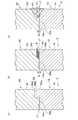
- (A) is sectional drawing which shows the butt
- (b) is sectional drawing which shows the butt
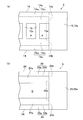
- (A) is a disassembled perspective view of the hollow container which concerns on 2nd embodiment of this invention
- (b) is sectional drawing which shows the butt
- FIG. 1 A method for joining members according to a first embodiment of the present invention will be described in detail with reference to the drawings.
- a hollow container 1 is manufactured by joining metal members together is illustrated.
- the hollow container 1 is used as a heat transfer member by flowing a fluid therein.
- “front and rear”, “left and right”, and “up and down” follow the arrows in FIG. 1 (based on the first member 2).
- the hollow container 1 includes a first member 2 and a second member 3.
- the material of the first member 2 and the second member 3 is not particularly limited as long as it is a metal capable of friction welding, but in this embodiment, both use aluminum alloy.
- the yield strength of the 1st member 2 and the 2nd member 3 is not restrict
- the first member 2 includes a bottom portion 11 having a rectangular shape in plan view, a first side wall portion 12 having a rectangular frame shape standing on the bottom portion 11, and a plurality of partition portions 13 formed inside the first side wall portion 12. It consists of and.
- the molding method of the first member 2 is not particularly limited, in the present embodiment, the first side wall portion 12 and the partition portion 13 are integrally formed by extrusion molding, and then the bottom portion 11 is joined to the end portion of the molded product. .
- the first vertical side portion 14 extends to a virtual boundary surface (side end surface) 14b. Further, the first lateral side portion 15 extends to a virtual boundary surface (side surface) 15e. The virtual boundary surface 14 b of the first vertical side portion 14 is connected to the virtual boundary surface 15 e of the first horizontal side portion 15.
- the upper end surface 14a is divided into two regions. The surface in contact with the lower end surface 24a in abutting step described later and the upper end surface 14a 1, and the upper end face 14a 2 of the plane away from the lower end surface 24a.
- the partition portion 13 has a plate shape and is connected to the first vertical side portions 14 and 14 at a right angle. A plurality of the partition portions 13 are arranged at equal intervals. A plurality of spaces formed by the first side wall portion 12 and the partition portion 13 are used as flow paths P, P,. The upper end surface 13a of the partition part 13 is flush with the upper end surfaces 14a and 15a.
- the second member 3 includes a bottom portion 21 having a rectangular shape in plan view and a second side wall portion 22 having a rectangular frame shape in a plan view hanging from the bottom portion 21.
- a concave portion Q composed of a bottom portion 21 and a second side wall portion 22 is formed inside the second member 3.
- the molding method of the second member 3 is not particularly limited, in the present embodiment, it is integrally molded by die casting.
- the second side wall portion 22 includes second vertical side portions 24 and 24 and second horizontal side portions 25 and 25.
- the second vertical side portions 24, 24 have a plate shape and are spaced apart from each other and arranged in parallel.
- the second lateral sides 25, 25 have a plate shape and are spaced apart from each other and arranged in parallel.
- the second vertical side portion 24 is perpendicular to the second horizontal side portion 25.
- the length and plate thickness of the second vertical side portion 24 are respectively equal to the length and plate thickness of the first vertical side portion 14. Further, the length and the plate thickness of the second lateral side portion 25 are equivalent to the length and the plate thickness of the first lateral side portion 15.
- the second vertical side portion 24 extends to a virtual boundary surface (side end surface) 24b. Further, the second horizontal side portion 25 extends to a virtual boundary surface (side surface) 25e. The virtual boundary surface 24 b of the second vertical side portion 24 is connected to the virtual boundary surface 25 e of the second horizontal side portion 25.
- notches 26 are formed on the outer sides of the lower end surfaces 24a and 24a, respectively.
- the notch 26 includes a bottom surface 26a and a side surface 26b perpendicular to the bottom surface 26a.
- the notch 26 is formed with a constant cross section along the entire length of the second vertical side 24 in the longitudinal direction.
- the height of the notch 26 (the height of the side surface 26b) is appropriately set depending on the materials of the first member 2 and the second member 3 and the friction welding conditions.
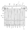
- FIG. 3 is a cross-sectional view of the hollow container according to the first embodiment.
- the hollow container 1 has the first member 2 and the second member 3 joined by friction welding.
- a weld metal W ⁇ b> 1 is formed over the outer periphery of the joint between the first member 2 and the second member 3.
- the weld metal W1 is a part formed by laser welding.
- a preparation process, a butt process, a friction welding process, and a welding process are performed.
- the preparation step is a step of preparing the first member 2 and the second member 3.
- the forming method of the first member 2 and the second member 3 is not particularly limited.
- the butting process is a process in which the first member 2 and the second member 3 are butted together.
- the upper end surfaces 14a 1 and 14a 1 of the first member 2 and the lower end surfaces (opposing surfaces) 24a and 24a of the second member 3 are brought into surface contact.
- the upper end surfaces 15a, 15a of the first member 2 and the lower end surfaces (opposing surfaces) 25a, 25a of the second member 3 are brought into surface contact.
- the outer peripheral surface of the first side wall portion 12 of the first member 2 and the outer peripheral surface of the second side wall portion 22 of the second member 3 are flush with each other. Thereby, the butt
- the butt step since the cutout portion 26 to the second vertical side portion 24 of the second member 3 is formed, leaving a slight gap to the upper end face 14a 2 and the bottom surface 26a facing To do.
- the upper end face 14a 2 that faces the bottom surface 26a and the bottom surface 26a corresponds to the "separation plane" in the claims.
- the first member 2 is fixed and the second member 3 is relatively moved. Therefore, in the butting process, the periphery of the first side wall portion 12 of the first member 2 is fixed by a fixing jig. Restrained to move.
- the friction welding process is a process of joining the first member 2 and the second member 3 by performing a friction process and a pressure welding process.
- the abutted first member 2 and second member 3 are pressed in a direction approaching each other.
- the first member 2 and the second member 3 are reciprocated relatively and linearly in parallel with the longitudinal direction of the first vertical side portion 14. In the present embodiment, the first member 2 is not moved, but only the second member 3 is linearly reciprocated.
- the friction step according to the present embodiment is rubbed upper end surface 14a 1 and the lower end surface 24a and the upper end surface 15a and the lower end surface 25a (see FIG. 4).
- the conditions in the friction process may be set as appropriate.
- the frequency is set to 100 to 260 Hz
- the amplitude is set to 1.0 to 2.0 mm
- the friction pressure is set to 20 to 60 MPa.
- the time for the friction process is set to about 5 to 10 seconds. When the friction process is completed, the process immediately proceeds to the pressure contact process.
- the first member 2 and the second member 3 are pressed in directions close to each other without being relatively moved.
- the conditions in the pressure contact process may be set as appropriate.
- the upset pressure is set to 60 to 80 MPa, and the time is set to about 3 to 5 seconds.
- the distance between the upper end face 14a 2 and the bottom surface 26a is equal to or less than half the previous friction welding.
- Burrs S generated in the outer, upper end face 14a 2 is accommodated in a space surrounded by the side surfaces 26b and the bottom surface 26a.
- flash S may protrude outside the outer surface.
- welding is performed using the burrs S formed on the outer sides of the butted portions J1 of the first member 2 and the second member 3 as a filler material.
- the type of welding is not particularly limited, but laser welding is performed in this embodiment. In the welding process, other types of welding methods such as arc welding may be used.
- the center line V1 of welding in the welding process and the bottom surface 26a are set to overlap, the center line V1 of welding and the butt portion J1 are separated from each other. To do. As described above, the hollow container 1 is formed.
- flash S can be accommodated between the said separation surfaces in the case of a friction welding process, and it can prevent that a burr
- burr S is discharged toward the outside while being guided to the upper end surface 14a 2 and the bottom surface 26a, so that it is prevented from irregularly bulging to the outside, and the upper end surface 14a 2 and the bottom surface
- the burr S can be collected between 26a.
- the outer surface of the hollow container (joined member) 1 can be finished cleanly by performing a welding process.
- flash S used as a filler material is accommodated between a pair of separation surfaces, since a filler material can be collected in a predetermined
- matched mutually among the 1st member 2 and the 2nd member 3 exhibit planar view rectangular frame shape, members can be joined.
- many burrs S tend to be generated on the side of the first vertical side portion 14 and the second vertical side portion 24 in the butting portion J ⁇ b> 1.
- the burr S can be effectively accommodated by providing a pair of spaced surfaces along the longitudinal direction of the portion 14. In the welding process, the welding center line V1 and the tip of the burr S may be set to be parallel to the bottom surface 26a.
- the center line V1 of the weld may be set to pass the middle point between the upper end face 14a 2 and the bottom surface 26a.
- the finished surface can be made clean by appropriately setting the center line V1 of the welding according to the generation form of the burrs S.
- the first modification shown in FIG. 6A is different from the first embodiment in that a separation surface is also provided inside the abutting portion J1.
- the first modification will be described with a focus on differences from the first embodiment.
- the second member 3A includes a bottom portion 21 and a rectangular frame-shaped second side wall portion 22 that hangs down from the bottom portion 21.
- the 2nd side wall part 22 is comprised by a pair of 2nd vertical side parts 24 and 24 which exhibit a plate shape, and a pair of 2nd horizontal side parts 25 and 25 which exhibit a plate shape.
- the second vertical side portion 24 is longer than the second horizontal side portion 25.
- Notches 26 and 27 are formed on the inner side and the outer side of the lower end surface 24 a of the second vertical side portion 24.
- the notches 26 and 27 are formed along the longitudinal direction of the second vertical side 24.
- the notch 26 includes a bottom surface 26a and a side surface 26b perpendicular to the bottom surface 26a.
- the notch 27 includes a bottom surface 27a and a side surface 27b perpendicular to the bottom surface 27a.
- a preparation process, a butt process, a friction welding process, and a welding process are performed.
- the preparation process is substantially equivalent to the first embodiment.
- the butting process is a process of causing the first member 2 and the second member 3A to abut.
- the upper end surface 14 a 1 of the first vertical side portion 14 and the lower end surface 24 a of the second vertical side portion 24 are abutted, and the upper end surface 15 a of the first horizontal side portion 15 and the second horizontal side portion 25 are The lower end surface 25a is abutted.
- matching part J2 is formed.
- the bottom surface 26a and the upper end surface 14a 2 facing the bottom surface 26a, the bottom surface 27a and the upper end surface 14a 2 facing the bottom surface 27a correspond to a “separating surface” in the claims.
- the friction welding process and the welding process are substantially the same as in the first embodiment.
- the same effect as the first embodiment can be obtained by the first modification.
- the flow path may be narrowed by the bulging of the burr S generated inside the hollow container 1A, which may hinder the flow of the fluid.
- burr is accommodated between a pair of spaced surfaces formed on the inner side to reduce or eliminate bulging of the burr to the inner side of the hollow container 1A. be able to.
- the second modification shown in FIG. 6B is different from the first embodiment in that a cutout portion 16 is provided also in the first member 2B.
- the second modification will be described with a focus on differences from the first embodiment.
- the 1st side wall part 12 of the 1st member 2B is comprised by the 1st vertical side parts 14 and 14 which exhibit plate shape, and the 1st horizontal side parts 15 and 15 which exhibit plate shape.
- the first side wall portion 12 has a rectangular frame shape in plan view.
- a notch 16 is formed outside the upper end surface 14 a of the first vertical side portion 14.
- the cutout portion 16 includes a bottom surface 16a and a side surface 16b perpendicular to the bottom surface 16a.
- the second member 3 is equivalent to the first embodiment.
- the notch 16 and the notch 26 have the same shape.
- a preparation process, a butt process, a friction welding process, and a welding process are performed.
- the preparation process is substantially the same as in the first embodiment.
- the butting process is a process of butting the first member 2B and the second member 3 together.
- the upper end surface 14a of the first vertical side portion 14 and the lower end surface 24a of the second vertical side portion 24 are abutted, and the upper end surface 15a of the first horizontal side portion 15 and the second horizontal side portion 25 are The lower end surface 25a is abutted.
- matching part J3 is formed.
- the bottom surface 16a of the notch 16 and the bottom surface 26a of the notch 26 face each other with a slight gap.
- the bottom surface 16a and the bottom surface 26a facing the bottom surface 16a correspond to a “separating surface” in the claims.
- the friction welding process is the same as in the first embodiment.
- laser welding is performed using a burr accommodated between the bottom surface (separation surface) 16a and the bottom surface (separation surface) 26a of the abutting portion J3 as in the first embodiment.
- the center line of welding and the butt J3 overlap each other.
- the same effect as in the first embodiment can be obtained even if the notch portions 16 and 26 are provided in both the first member 2B and the second member 3 to form the separation surfaces (16a and 26a). Obtainable.
- the third modification shown in FIG. 7 differs from the first embodiment in that a chamfered portion 26C is provided on the second member 3C.
- the difference from the first embodiment will be mainly described.
- the first member 2 uses the same member as in the first embodiment.
- the second member 3 ⁇ / b> C includes a bottom portion 21 and a second side wall portion 22 depending from the bottom portion 21.
- the second side wall portion 22 has a rectangular frame shape in plan view.
- the second side wall portion 22 includes second vertical side portions 24 and 24 and second horizontal side portions 25 and 25.
- a chamfered portion 26 ⁇ / b> C that is chamfered along the longitudinal direction is formed on the outer side of the lower end surface 24 a of the second vertical side portion 24.
- the chamfered portion 26 ⁇ / b> C is formed by chamfering the corner portion between the lower end surface 24 a and the outer surface 24 c of the second vertical side portion 24. In this embodiment, it is C chamfering, but round chamfering may be used.
- a preparation process, a butt process, a friction welding process, and a welding process are performed.
- the preparation process is equivalent to the first embodiment.
- the butting process is a process of butting the first member 2 and the second member 3C.
- the upper end surface 14 a 1 of the first vertical side portion 14 and the lower end surface 24 a of the second vertical side portion 24 are abutted, and the upper end surface 15 a of the first horizontal side portion 15 and the second horizontal side portion 25 are The lower end surface 25a is abutted.
- matching part J4 is formed.
- the butt step to face with a gap from the chamfered surface 26Ca of the upper end surface 14a 2 and the chamfered portion 26C.
- the upper end surface 14a 2 and the chamfered surface 26Ca facing the upper end surface 14a 2 correspond to a “separating surface” in the claims.
- the welding step the welding burrs accommodated in the gap between the upper end face 14a 2 and the chamfered surface 26Ca as filler material.
- the second member 3C provided chamfer 26C, it is possible to accommodate the burrs generated by the friction welding between the upper end face 14a 2 and the chamfered surface 26Ca, first An effect equivalent to that of the embodiment can be obtained.
- matching part J4 is chamfered, you may chamfer inside.
- the chamfered portion 26 is not limited to the chamfering process, and may be formed by die casting.
- the second embodiment differs from the first embodiment in that the frame-shaped first side wall portion and the plate-shaped lid member are joined.
- the second embodiment will be described with a focus on the differences from the first embodiment.
- the first member 2D includes a first side wall portion 12.
- the 1st side wall part 12 is comprised by the 1st vertical side parts 14 and 14 which exhibit plate shape, and the 1st horizontal side parts 15 and 15 which exhibit plate shape.
- the first vertical side portion 14 is longer than the first horizontal side portion 15.
- the first side wall portion 12 has a rectangular frame shape in plan view.
- a notch 26 is formed outside the upper end surface 14a of the first vertical side 14.
- the notch 26 includes a bottom surface 26a and a side surface 26b perpendicular to the bottom surface 26a.
- the notch portion 26 is formed over the entire longitudinal direction of the first vertical side portion 14.
- the second member 3D has a rectangular plate shape in plan view.
- the outer edge of the second member 3 ⁇ / b> D has the same shape as the outer edge of the first side wall portion 12.
- a frame-like facing surface 31 a is formed at a portion of the second member 3 ⁇ / b> D that faces the first vertical side portion 14 and the first horizontal side portion 15.
- part which opposes the 1st vertical side part 14 among the opposing surfaces 31a is divided into two area
- a preparation process, a butt process, a friction welding process, and a welding process are performed.
- the preparation step is a step of preparing the first member 2D and the second member 3D.
- the molding method of the first member 2D and the second member 3D is not particularly limited.
- the upper end surfaces 14a and 14a of the first member 2D and the facing surfaces 31a 1 and 31a 1 of the second member 3D are brought into surface contact. Further, the upper end surfaces 15a and 15a of the first member 2D are brought into surface contact with the facing surfaces 31a and 31a. Thereby, the butt
- the butt step since the cutout portion 26 to the first vertical side portion 14 of the second member 3 is formed, to face at a slight gap from the opposing surface 31a 2 and the bottom surface 26a. Facing surface 31a 2 that faces the bottom surface 26a and the bottom surface 26a corresponds to the "separation plane" in the claims.
- the friction welding process is a process of joining the first member 2D and the second member 3D by performing the friction process and the pressure welding process.
- the abutted first member 2D and second member 3D are pressed in a direction approaching each other.
- the first member 2D and the second member 3D are reciprocated relatively and linearly in parallel with the longitudinal direction of the first vertical side portion 14. In the present embodiment, the first member 2D is not moved, and only the second member 3D is linearly reciprocated.
- the mother in the friction step according to the present embodiment is rubbed and the upper end face 14a and the opposing surface 31a 2 and the upper end surface 15a and the opposing surface 31a frictional heat is generated, the softened By discharging the material to the outside, the height of the part of the first side wall portion 12 and the second side wall portion 22 that are rubbed together gradually decreases.
- welding is performed using a burr formed outside the butted portion J5 of the first member 2D and the second member 3D as a filler material.
- the type of welding is not particularly limited, but laser welding is performed in this embodiment. In the welding process, other types of welding methods such as arc welding may be used. Thus, the hollow container 1D is formed.
- the same effect as that of the first embodiment can be obtained even when the second member 3D is formed as a plate-like lid as in the method for joining members according to the second embodiment.
- the notch portion 26 is provided only in the first member 2D.
- the notch portion 26 may be provided only in the second member 3D, or the notch portions may be provided in both the first member 2D and the second member 3D. It may be provided.
- the notch is provided only in the vertical side, but it may be provided only in the horizontal side, or may be provided in both the vertical side and the horizontal side.
- the reciprocating motion is performed in parallel with the vertical side portion.
- the reciprocating motion may be performed in parallel with the horizontal side portion or may be reciprocated obliquely with respect to the vertical side portion. It may be moved.
- the shape of the portion to be abutted between the first member and the second member is a rectangular frame shape in plan view, but other polygonal shapes such as a triangular frame shape, a hexagonal frame shape, etc. You may make it exhibit a frame shape.
- a bottomed tubular member or a tubular member may be formed by joining a first member and a second member, one or both of which has a rectangular tubular shape.
- the shape of the part to be abutted between the first member and the second member may be another polygonal shape such as a triangle or a hexagon.
- the solid first member and the second member may be joined.
- the present invention can be applied to a case where polygonal columns such as quadrangular columns or hexagonal columns are joined.
- the polygonal columns may have the same cross-sectional shape or different cross-sectional shapes.
- the third embodiment is different from the other embodiments in that a cylindrical member is formed by joining a cylindrical first member and a second member.
- a cylindrical member is formed by joining a cylindrical first member and a second member.
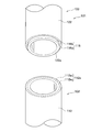
- the 1st member 102 which exhibits cylindrical shape, and the 2nd member 103 which exhibits cylindrical shape are joined.
- a description will be given focusing on the parts that are different from the first embodiment.
- the first member 102 includes a cylindrical first side wall portion 112.
- the upper end surface 112a of the first side wall 112 is divided into two regions. The surface in contact with the lower end surface 122a in abutting step described later and the upper end surface 112a 1, and the upper end face 112a 2 a plane spaced from the lower end surface 122a.
- the upper end face 112a 1 is formed inside the upper end surface 112a, the upper end face 112a 2 is formed on the outside.
- the second member 103 is composed of a cylindrical second side wall portion 122.
- the outer diameter and plate thickness of the second side wall portion 122 are equal to the outer diameter and plate thickness of the first side wall portion 112.
- a notch 116 is formed outside the lower end surface 122 a of the second side wall 122.
- the notch 116 is formed by a bottom surface 116a and a 116b perpendicular to the bottom surface 116a.
- the notch 116 is formed over the entire circumference.
- FIG. 10 is a cross-sectional view of a cylindrical member according to the third embodiment.
- the cylindrical member 101 has a first member 102 and a second member 103 joined by friction welding.
- a weld metal W ⁇ b> 1 is formed over the outer periphery of the joint between the first member 102 and the second member 103.
- the weld metal W1 is a part formed by laser welding.
- a preparation process, a butt process, a friction welding process, and a welding process are performed.
- the preparation step is a step of preparing the first member 102 and the second member 103.
- the molding method of the first member 102 and the second member 103 is not particularly limited.
- the butting process is a process in which the first member 102 and the second member 103 are butted together.
- the butt step matched to the upper end face 112a 1 of the first member 102 and a lower end surface 122a of the second member 103.
- matching part J6 is formed.
- the butt step since the notch 116 on the second member 103 is formed, the upper end face 112a 2 and the bottom surface 116a faces at a slight gap.
- the upper end face 112a 2 which faces the bottom surface 116a and bottom surface 116a corresponds to the "separation plane" in the claims.
- the first member 102 is fixed and the second member 103 is relatively moved. Therefore, in the butting process, the periphery of the first side wall portion 112 of the first member 102 is fixed by a fixing jig. Restrained to move.
- the friction welding process is a process of joining the first member 102 and the second member 103 by performing a friction process and a pressure welding process.
- the friction step the abutted first member 102 and second member 103 are pressed in a direction approaching each other. Then, the second member 103 is rotated in the circumferential direction around the axial center of the first member 102.
- burrs are generated when the softened base material is pushed out to the inside and outside of the joint.
- the distance between the upper end face 112a 2 and the bottom surface 116a is approximately half before friction welding. Burrs generated in the outer, upper end face 112a 2, is accommodated in a space surrounded by the bottom surface 116a and side 116 b.
- the welding process is substantially equivalent to the first embodiment.
- first member 102 and the second member 103 have a cylindrical shape as in the present embodiment, the same effect as that of the first embodiment can be obtained.
- cylindrical members were joined, it is not limited to this. It is sufficient that at least one of the members to be joined is cylindrical.
- a bottom portion may be provided on either the first member or the second member to form a bottomed cylindrical member or a hollow cylindrical member.
- you may join a solid 1st member and a 2nd member.
- the present invention can also be applied when joining cylinders.
- the portion of the first member where the second member abuts has a frame shape in plan view means that the second member of the first member abuts.
- the shape of the portion when viewed in plan includes other polygonal frame shapes such as a cylindrical shape, a triangular frame shape, a rectangular frame shape, and a hexagonal frame shape.
Landscapes
- Engineering & Computer Science (AREA)
- Physics & Mathematics (AREA)
- Optics & Photonics (AREA)
- Mechanical Engineering (AREA)
- Plasma & Fusion (AREA)
- Pressure Welding/Diffusion-Bonding (AREA)
Abstract
Description
本発明の第一実施形態に係る部材の接合方法について図面を参照して詳細に説明する。図1に示すように、本実施形態の部材の接合方法では、金属部材同士を接合して中空容器1を製造する場合を例示する。中空容器1は、例えば、内部に流体を流して伝熱部材として用いられる。説明における「前後」、「左右」、「上下」は図1の矢印に従う(第一部材2を基準とする)。
なお、溶接工程の際には、底面26aに平行で、かつ、溶接の中心線V1とバリSの先端とが重なるように設定してもよい。また、底面26aに平行で、かつ、溶接の中心線V1が、上端面14a2と底面26aとの間の中点を通るように設定してもよい。バリSの発生形態に応じて溶接の中心線V1を適宜設定することで、仕上がり面をきれいにすることができる。
図6の(a)に示す第一変形例は、突合せ部J1の内側にも離間面を設けた点で第一実施形態と相違する。第一変形例では、第一実施形態と相違する点を中心に説明する。
図6の(b)に示す第二変形例は、第一部材2Bにも切欠き部16を設けた点で第一実施形態と相違する。第二変形例では、第一実施形態との相違点を中心に説明する。
図7に示す第三変形例は、第二部材3Cに面取り部26Cを設けた点で第一実施形態と相違する。第三変形例では、第一実施形態との相違点を中心に説明する。
図8の(a)及び(b)に示すように、第二実施形態では、枠状の第一側壁部と板状の蓋部材を接合する点で第一実施形態と相違する。第二実施形態では第一実施形態と相違する部分を中心に説明する。
次に、本発明の第三実施形態について説明する。第三実施形態では、円筒状を呈する第一部材及び第二部材を接合して筒状部材を形成する点で他の実施形態と相違する。第三実施形態では、図9に示すように円筒状を呈する第一部材102と、円筒状を呈する第二部材103とを接合する。第三実施形態では、第一実施形態と相違する部分を中心に説明する。
2 第一部材
3 第二部材
11 底部
12 第一側壁部
13 仕切り部
14 第一縦辺部
15 第一横辺部
21 底部
22 第二側壁部
24 第二縦辺部
25 第二横辺部
26 切欠き部
Claims (5)
- 第一部材と、前記第一部材に対向する第二部材とを準備する準備工程と、
前記第一部材の端面と前記端面に対向する第二部材の対向面とを突き合せて摩擦圧接を行う摩擦圧接工程と、
前記摩擦圧接工程で形成されたバリを溶加材として溶接を行う溶接工程と、を含み、
前記摩擦圧接工程では、前記第一部材と前記第二部材との突合せ部の外側において、摩擦圧接の開始時に間隔をあけて対向する一対の離間面を設けておき、当該一対の離間面の間に摩擦圧接で発生する前記バリを収容することを特徴とする部材の接合方法。 - 前記第一部材のうち前記第二部材が突き合わされる部位は平面視枠状を呈し、
前記摩擦圧接工程では、前記第一部材と前記第二部材との突合せ部の内側において、摩擦圧接の開始時に間隔をあけて対向する一対の離間面を設けておき、当該一対の離間面の間に摩擦圧接で発生する前記バリを収容することを特徴とする請求の範囲第1項に記載の部材の接合方法。 - 前記第一部材のうち前記第二部材が突き合わされる部位は平面視矩形枠状を呈し、板状の一対の第一縦辺部と前記第一縦辺部よりも長さ寸法の小さい板状の一対の第一横辺部とを備え、
前記第一縦辺部の長手方向に沿って前記一対の離間面を形成しておき、
前記摩擦圧接工程では、前記第一部材及び前記第二部材を前記第一縦辺部と平行に相対的に往復移動させることを特徴とする請求の範囲第1項又は請求の範囲第2項に記載の部材の接合方法。 - 前記第一部材のうち前記第二部材が突き合わされる部位は円筒状を呈し、
前記摩擦圧接工程では、前記第一部材の軸中心周りに相対的に回転させることを特徴とする請求の範囲第1項又は請求の範囲第2項に記載の部材の接合方法。 - 前記第一部材のうち前記第二部材が突き合わされる部位は円柱状を呈し、
前記摩擦圧接工程では、前記第一部材の軸中心周りに相対的に回転させることを特徴とする請求の範囲第1項に記載の部材の接合方法。
Priority Applications (2)
| Application Number | Priority Date | Filing Date | Title |
|---|---|---|---|
| CN201480025246.2A CN105163893B (zh) | 2013-05-09 | 2014-04-25 | 构件的接合方法 |
| KR1020157027900A KR101708590B1 (ko) | 2013-05-09 | 2014-04-25 | 부재의 접합 방법 |
Applications Claiming Priority (2)
| Application Number | Priority Date | Filing Date | Title |
|---|---|---|---|
| JP2013099546A JP6028674B2 (ja) | 2013-05-09 | 2013-05-09 | 部材の接合方法 |
| JP2013-099546 | 2013-05-09 |
Publications (1)
| Publication Number | Publication Date |
|---|---|
| WO2014181720A1 true WO2014181720A1 (ja) | 2014-11-13 |
Family
ID=51867201
Family Applications (1)
| Application Number | Title | Priority Date | Filing Date |
|---|---|---|---|
| PCT/JP2014/061780 Ceased WO2014181720A1 (ja) | 2013-05-09 | 2014-04-25 | 部材の接合方法 |
Country Status (5)
| Country | Link |
|---|---|
| JP (1) | JP6028674B2 (ja) |
| KR (1) | KR101708590B1 (ja) |
| CN (1) | CN105163893B (ja) |
| TW (1) | TWI579084B (ja) |
| WO (1) | WO2014181720A1 (ja) |
Families Citing this family (1)
| Publication number | Priority date | Publication date | Assignee | Title |
|---|---|---|---|---|
| JP7140062B2 (ja) * | 2019-06-28 | 2022-09-21 | 日本軽金属株式会社 | 摩擦攪拌接合方法 |
Citations (4)
| Publication number | Priority date | Publication date | Assignee | Title |
|---|---|---|---|---|
| JP2003019574A (ja) * | 2001-07-06 | 2003-01-21 | Hitachi Metals Ltd | 管状部材 |
| WO2004033143A1 (en) * | 2002-10-08 | 2004-04-22 | Scaglia Spa | Method to make mechanical components for fluid-dynamic devices, compressors or motors operating at high pressure, and mechanical components thus achieved |
| US20100159274A1 (en) * | 2008-06-25 | 2010-06-24 | Gm Global Technology Operations, Inc. | Friction-welded assembly with interlocking feature and method for forming the assembly |
| WO2013058086A1 (ja) * | 2011-10-21 | 2013-04-25 | 日本軽金属株式会社 | 蓋付容器の製造方法及び接合方法 |
Family Cites Families (9)
| Publication number | Priority date | Publication date | Assignee | Title |
|---|---|---|---|---|
| JPS50123545A (ja) * | 1974-03-18 | 1975-09-29 | ||
| JPS6233081A (ja) * | 1985-08-02 | 1987-02-13 | Inoue Japax Res Inc | 摩擦溶接装置 |
| US8740042B2 (en) * | 2006-07-19 | 2014-06-03 | Nippon Light Metal Company, Ltd. | Friction-welded part and method of friction welding |
| CN101200020A (zh) * | 2006-12-11 | 2008-06-18 | 西门子威迪欧汽车电子(长春)有限公司 | 旋转摩擦焊接加工方法和采用该方法制造的结构件 |
| JP5243083B2 (ja) * | 2008-04-01 | 2013-07-24 | 株式会社豊田自動織機 | 摩擦圧接方法 |
| JP2011102634A (ja) * | 2009-11-12 | 2011-05-26 | Nippon Light Metal Co Ltd | ダンパーおよびダンパー用アウターシェル |
| JP2012240115A (ja) * | 2011-05-24 | 2012-12-10 | Toyota Motor Corp | 回転摩擦圧接方法および接合体 |
| JP5900410B2 (ja) * | 2013-05-09 | 2016-04-06 | 日本軽金属株式会社 | 部材の接合方法 |
| JP5915785B2 (ja) * | 2015-01-29 | 2016-05-11 | 日本軽金属株式会社 | 中空容器の製造方法 |
-
2013
- 2013-05-09 JP JP2013099546A patent/JP6028674B2/ja active Active
-
2014
- 2014-04-25 WO PCT/JP2014/061780 patent/WO2014181720A1/ja not_active Ceased
- 2014-04-25 CN CN201480025246.2A patent/CN105163893B/zh not_active Expired - Fee Related
- 2014-04-25 KR KR1020157027900A patent/KR101708590B1/ko not_active Expired - Fee Related
- 2014-05-06 TW TW103116039A patent/TWI579084B/zh not_active IP Right Cessation
Patent Citations (4)
| Publication number | Priority date | Publication date | Assignee | Title |
|---|---|---|---|---|
| JP2003019574A (ja) * | 2001-07-06 | 2003-01-21 | Hitachi Metals Ltd | 管状部材 |
| WO2004033143A1 (en) * | 2002-10-08 | 2004-04-22 | Scaglia Spa | Method to make mechanical components for fluid-dynamic devices, compressors or motors operating at high pressure, and mechanical components thus achieved |
| US20100159274A1 (en) * | 2008-06-25 | 2010-06-24 | Gm Global Technology Operations, Inc. | Friction-welded assembly with interlocking feature and method for forming the assembly |
| WO2013058086A1 (ja) * | 2011-10-21 | 2013-04-25 | 日本軽金属株式会社 | 蓋付容器の製造方法及び接合方法 |
Also Published As
| Publication number | Publication date |
|---|---|
| KR20150123945A (ko) | 2015-11-04 |
| CN105163893A (zh) | 2015-12-16 |
| TWI579084B (zh) | 2017-04-21 |
| JP6028674B2 (ja) | 2016-11-16 |
| JP2014217868A (ja) | 2014-11-20 |
| KR101708590B1 (ko) | 2017-02-20 |
| TW201446371A (zh) | 2014-12-16 |
| CN105163893B (zh) | 2017-09-22 |
Similar Documents
| Publication | Publication Date | Title |
|---|---|---|
| TWI558627B (zh) | Method for manufacturing hollow container and joining method of member | |
| WO2017013978A1 (ja) | 接合方法及びヒートシンクの製造方法 | |
| JP6028674B2 (ja) | 部材の接合方法 | |
| GB2406536A (en) | Friction sheet welding method | |
| JP5838995B2 (ja) | 部材の接合方法 | |
| WO2013058086A1 (ja) | 蓋付容器の製造方法及び接合方法 | |
| JP5900410B2 (ja) | 部材の接合方法 | |
| JP6487623B2 (ja) | 接合方法 | |
| JP5630480B2 (ja) | 蓋付容器の製造方法 | |
| JP5157759B2 (ja) | 角形鋼管部材 | |
| JP5239649B2 (ja) | 柱用角形鋼管部材 | |
| KR101533547B1 (ko) | 덮개를 구비한 용기의 제조 방법 | |
| JP5435109B2 (ja) | 接合方法 | |
| JP5298761B2 (ja) | 円形鋼管部材 | |
| JP2016036836A (ja) | 摩擦攪拌接合用工具及び接合方法 | |
| JP2008057782A5 (ja) | ||
| JP2013159171A (ja) | 自転車フレームの製造方法及び自転車フレーム | |
| JP2008240814A (ja) | 粘弾性ダンパーの製造方法 | |
| JP2013071478A (ja) | フレーム構造体の組立方法 | |
| JP2004027741A (ja) | 柱材用鋼管の継手構造 |
Legal Events
| Date | Code | Title | Description |
|---|---|---|---|
| WWE | Wipo information: entry into national phase |
Ref document number: 201480025246.2 Country of ref document: CN |
|
| 121 | Ep: the epo has been informed by wipo that ep was designated in this application |
Ref document number: 14794861 Country of ref document: EP Kind code of ref document: A1 |
|
| ENP | Entry into the national phase |
Ref document number: 20157027900 Country of ref document: KR Kind code of ref document: A |
|
| NENP | Non-entry into the national phase |
Ref country code: DE |
|
| 122 | Ep: pct application non-entry in european phase |
Ref document number: 14794861 Country of ref document: EP Kind code of ref document: A1 |