WO2014179949A1 - 电子烟连接座及电子烟雾化器 - Google Patents
电子烟连接座及电子烟雾化器 Download PDFInfo
- Publication number
- WO2014179949A1 WO2014179949A1 PCT/CN2013/075330 CN2013075330W WO2014179949A1 WO 2014179949 A1 WO2014179949 A1 WO 2014179949A1 CN 2013075330 W CN2013075330 W CN 2013075330W WO 2014179949 A1 WO2014179949 A1 WO 2014179949A1
- Authority
- WO
- WIPO (PCT)
- Prior art keywords
- electronic cigarette
- connecting seat
- atomizer
- groove
- filling groove
- Prior art date
Links
Images


Classifications
-
- A—HUMAN NECESSITIES
- A24—TOBACCO; CIGARS; CIGARETTES; SIMULATED SMOKING DEVICES; SMOKERS' REQUISITES
- A24F—SMOKERS' REQUISITES; MATCH BOXES; SIMULATED SMOKING DEVICES
- A24F40/00—Electrically operated smoking devices; Component parts thereof; Manufacture thereof; Maintenance or testing thereof; Charging means specially adapted therefor
- A24F40/40—Constructional details, e.g. connection of cartridges and battery parts
-
- A—HUMAN NECESSITIES
- A24—TOBACCO; CIGARS; CIGARETTES; SIMULATED SMOKING DEVICES; SMOKERS' REQUISITES
- A24F—SMOKERS' REQUISITES; MATCH BOXES; SIMULATED SMOKING DEVICES
- A24F40/00—Electrically operated smoking devices; Component parts thereof; Manufacture thereof; Maintenance or testing thereof; Charging means specially adapted therefor
- A24F40/10—Devices using liquid inhalable precursors
Definitions
- the present invention relates to electronic cigarette technology, and more particularly to an electronic cigarette connector and an electronic cigarette atomizer.
- E-cigarette is an electronic product that uses a heating wire to heat and atomize the liquid to provide a cigarette substitute for the smoker.
- the heated liquid smoke becomes an aerosol, and passes through the vent pipe and reaches the outside of the electronic cigarette from the opening of the nozzle cover.
- the electronic cigarette is generally divided into an atomizer assembly (1) and a battery rod assembly (2), which are connected together by a joint (900).
- a sealing ring (800) is added between the connecting seat (900) and the outer wall to prevent the oil from leaking out from the gap between the connecting seat (900) and the outer wall.
- the problem to be solved by the invention is that the assembly method of the existing electronic cigarette connecting seat is complicated, the production defect rate is high, and the sealing effect is poor, providing a complicated assembly process and high production failure rate. And the defect of poor sealing effect provides an electronic cigarette connecting seat and an electronic cigarette atomizer to solve the above problems.
- an electronic cigarette connecting seat comprising a top cover, and a side wall is arranged around the edge of the top cover; the top cover is provided with a through hole, the inner side of the side wall is provided with a thread; the outer side of the side wall is provided There is at least one filling tank filled with a sealing filler.
- the sealing filler is an adhesive.
- the filling groove is an annular groove surrounding the outer peripheral surface of the side wall.
- the filling groove is a plurality of annular grooves surrounding the outer peripheral surface of the side wall, and each of the annular grooves is spaced apart from each other and arranged in parallel.
- the filling groove is a linear groove, a diagonal groove, an arc groove or a wave groove provided along the outer circumferential surface of the side wall and the axial direction.
- the filling groove is a textured slit provided outside the side wall.
- the invention also provides an electronic cigarette atomizer comprising a nozzle, an oil storage cotton, a fiberglass tube, a heating wire assembly, an upper electrode and an insulating ring which are sequentially disposed in the outer sleeve of the atomizer, and further comprises the invention provided by the invention
- An electronic cigarette connecting seat the electronic cigarette connecting seat is sleeved in the outer sleeve of the atomizer away from one end of the nozzle, and the outer side of the side wall of the electronic cigarette connecting seat is fitted to the inner side of the outer sleeve of the atomizer; the outer side of the side wall
- At least one filling tank is provided, and the filling tank is filled with a sealing filler.
- the electronic cigarette connecting seat comprises a top cover, and a side wall is arranged around the edge of the top cover; the top cover is provided with a through hole, and the inner side of the side wall is provided with a thread.
- the sealing filler is an adhesive
- the filling groove is an annular groove surrounding the outer peripheral surface of the side wall.
- the filling groove is a plurality of annular grooves surrounding the outer peripheral surface of the side wall, and each of the annular grooves is spaced apart from each other and disposed in parallel.
- the filling groove is a linear groove, a diagonal groove, an arc groove or a wave groove provided along the outer circumferential surface of the side wall and the axial direction.
- the filling groove is a textured slit provided outside the side wall.
- the upper electrode passes through the insulating ring, and the insulating ring is embedded in the through hole of the connecting cover, and the connecting seat is electrically isolated from the upper electrode.
- the fiberglass tube has a hollow structure and is installed inside the outer sleeve of the atomizer, and has a gap with the inner wall of the outer sleeve of the atomizer, and the oil storage cotton is installed in the gap.
- the electronic cigarette connecting seat is provided with chamfering.
- the electronic cigarette connecting seat is in an interference fit or a fitting fit with the outer sleeve of the atomizer.
- the electronic cigarette connecting seat and the electronic cigarette atomizer of the invention By implementing the electronic cigarette connecting seat and the electronic cigarette atomizer of the invention, it is not necessary to re-design the connecting seat, and the filling groove is filled in the outer side of the connecting seat to fill the glue to provide a good sealing property and avoid the oil storage cotton.
- the smoke oil flows into the battery assembly; the whole assembly process is simple, the yield rate is high, and the utility model can be applied to the existing connecting seat, and the applicability is strong.
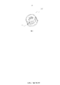
- FIG. 1 is a schematic view showing the external structure of an atomizer assembly and a battery rod assembly of an electronic cigarette;
- Figure 2 is a cross-sectional view of a conventional electronic cigarette atomizer
- FIG. 3 is a perspective view of a conventional electronic cigarette connecting seat
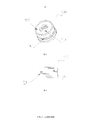
- Figure 4 is a cross-sectional view of the electronic cigarette atomizer of the present invention.
- Figure 5 is a perspective view of a first embodiment of the electronic cigarette connector of the present invention.
- Figure 5b is a side view of the first embodiment of the electronic cigarette connector of the present invention.
- Figure 6 is a schematic view showing the first embodiment of the electronic cigarette connector of the present invention mounted on an electronic cigarette atomizer;
- Figure 7 is a perspective view showing a second embodiment of the electronic cigarette connecting seat of the present invention.
- Figure 8 is a perspective view showing a third embodiment of the electronic cigarette connecting seat of the present invention.
- Figure 9 is a side view of a third embodiment of the electronic cigarette connector of the present invention.
- Figure 10 is a schematic view showing the third embodiment of the electronic cigarette connector of the present invention mounted on an electronic aerosolizer.
- the outer side of the connector 900 needs to be sleeved with a soft rubber seal 800 to achieve the sealing function.
- a soft rubber seal 800 to achieve the sealing function.
- the present invention is primarily directed to improvements in the connector 900 of an electronic cigarette.
- the connecting base 900 includes a top cover 903.
- a side wall 902 is disposed around the edge of the top cover 903; a filling groove 901 is disposed outside the side wall 902, and the filling groove 901 is filled with a sealing filler such as an adhesive such as various suitable glues.
- the glue-filled connector 900 is embedded from the bottom of the nebulizer outer sleeve 200, and the outside of the side wall 902 of the connector 900 and the nebulizer outer sleeve 200 are in close contact.
- the diameters of the two should be matched to each other, and a complete electronic aerosolizer can be formed by an interference fit or a fitting fit.
- the connector 900 is provided with a chamfer.
- a through hole 904 is defined in the top cover of the connector 900 for the passage of electrodes in the atomizer to be coupled to corresponding electrodes in the battery rod assembly.
- a thread is provided inside the side wall 902 of the connector 900 for the screw connection of the atomizer assembly 1 and the battery rod assembly 2.
- the filling groove 901 is disposed to surround the connecting base 900.
- An annular groove on the outer side of the side wall, the annular groove may be provided in one or more channels, and the annular grooves are parallel to each other. After the glue in the annular groove is dried, the gap between the connecting seat 900 and the outer sleeve 200 of the atomizer is completely blocked, thereby achieving sealing of the oil.
- the atomizer of the connector 900 of the present invention is further included
- the nozzle 100, the oil storage cotton 300, the fiberglass tube 400, the heating wire assembly 500, the upper electrode 600, and the insulating ring 700 are disposed in the outer tube sleeve 200 of the atomizer, in order from the top end to the bottom end.
- the upper electrode 600 passes through the insulating ring 700, and the insulating ring 700 is inserted into the top cover through hole 904 of the connecting base 900 to electrically isolate the connecting base 900 from the upper electrode 600.
- the fiberglass tube 400 has a hollow structure and is installed inside the outer sleeve 200 of the atomizer, and has a gap with the inner wall of the outer sleeve 200 of the atomizer, and the oil storage cotton 300 is installed in the gap.
- the heating wire assembly 500 heats and atomizes the liquid smoke in the oil storage cotton 300, and the atomized tobacco oil advances along the hollow fiberglass tube 400 and flows out from the suction nozzle 100.
- the filling groove 901 on the connecting base 900 may have other forms.
- the filling groove 901 on the connecting base 900 is perpendicular to the top cover direction (ie, along the edge).
- the two filling grooves have different advantages: in the first embodiment, the annular filling groove is better in sealing because it corresponds to the inner wall of the outer sleeve 200 of the entire atomizer; and the longitudinal linear filling groove can be enhanced.
- the rotational friction of the connector 900 relative to the inner wall of the outer sleeve 200 of the nebulizer allows the battery stem assembly 2 and the nebulizer assembly 1 to be more stably screwed.
- the longitudinal straight groove in the second embodiment is set as an inclined straight groove, that is, the direction of the straight groove is at an angle or a wave with the plane of the connecting seat cover.
- the annular groove in the first embodiment and the longitudinal linear groove in the second embodiment are simultaneously disposed on the connecting base 900, so that the connecting seat 900 has the advantages of both filling grooves.
- the diameter of the electronic cigarette connector 900 is set to be equal to the inner diameter of the outer sleeve 200 of the atomizer, and the two are fitted and fitted.
- the inner diameter of the nebulizer outer cover 200 is slightly smaller than the outer diameter of the electronic cigarette connector 900, and the two are interference fit. Since the sealing ring 800 is no longer sleeved outside the side wall of the electronic cigarette connecting seat 900, the electronic cigarette connecting seat 900 is not blocked by the friction of the sealing ring 800 when being inserted into the atomizer outer cover 200, and the installation process is easier. .
- the filling groove 901 is arranged as a mesh grooving, and the twill grooves of the two angles intersect each other to form a net as shown in FIG. 8 and FIG. Grid-shaped grooving.
- the advantage of using such a filling groove 901 is that the intersecting grooves communicate with each other, and a glue or an adhesive is filled in one place of the filling groove 901, so that it can flow along the communicating groove to the entire filling groove 901, and the sizing is performed.
- the method is simpler and the distribution of glue is more uniform.
- a filling groove is distributed on the outer wall region of the entire electronic cigarette connecting seat 900, which can better fit the atomizer outer sleeve 200.
- the electronic cigarette connector 900 is made stronger.
Landscapes
- Electrostatic Spraying Apparatus (AREA)
- Catching Or Destruction (AREA)
- Packaging Of Annular Or Rod-Shaped Articles, Wearing Apparel, Cassettes, Or The Like (AREA)
Abstract
一种电子烟连接座(900)及电子烟雾化器,该连接座(900)包括顶盖(903),围绕顶盖(903)边缘设有侧壁(902);侧壁(902)外侧设有填充槽(901),填充槽(901)内填充有胶水。根据本发明,无需重新对连接座进行设计开模,在连接座的外侧削出填充槽填入胶水就能提供良好的密封性,避免储油棉中的烟油流到电池组件中;整个装配工艺简单,良品率较高,能够应用在现有的连接座上,适用性强。
Description
本发明涉及电子烟技术,更具体地说,涉及一种电子烟连接座及电子烟雾化器。
电子烟是一种利用加热丝对烟液进行加热,使之雾化的电子产品,为吸烟者提供一种香烟的替代品。加热后的烟液变成气雾,通过通气管后从吸嘴盖的开口到达电子烟的外部。如图1至3所示,通常电子烟分成雾化器组件(1)和电池杆组件(2),通过连接座(900)将两者连接在一起。为了实现密封效果,在连接座(900)和外壁之间加装密封圈(800),以防止烟油从连接座(900)与外壁之间的间隙漏出。
但是这种方式需要重新开模具,装配工艺较复杂,生产不良率高,并且密封效果较差。
本发明要解决的问题是:针对现有的电子烟连接座的密封方式装配工艺较复杂,生产不良率高,并且密封效果较差的缺陷,提供一种装配工艺较复杂,生产不良率高,并且密封效果较差的缺陷,提供一种电子烟连接座及电子烟雾化器以解决上述问题。
本发明解决上述问题的方案是,构造一种电子烟连接座,包括顶盖,围绕顶盖边缘设有侧壁;顶盖开设有通孔,侧壁的内侧设有螺纹;侧壁外周向设有至少一填充槽,填充槽内填充有密封填充剂。
本发明的电子烟连接座,密封填充剂为粘接剂。
本发明的电子烟连接座,填充槽为一环绕所述侧壁外周表面的环形槽。
本发明的电子烟连接座,填充槽为多个环绕所述侧壁外周表面的环形槽,每个环形槽相互间隔、平行设置。
本发明的电子烟连接座,填充槽为沿侧壁外周表面、轴向方向设置的直线槽、斜线槽、弧线槽或波浪槽。
本发明的电子烟连接座,填充槽为设置在侧壁外的网纹切槽。
本发明还提供一种电子烟雾化器,包括依次设置在雾化器外管套内的吸嘴、储油棉、玻纤管、电热丝组件、上电极和绝缘环,还包括本发明提供的电子烟连接座,电子烟连接座套合在远离吸嘴一端的所述雾化器外管套内,且电子烟连接座的侧壁外侧与雾化器外管套内侧贴合;侧壁外周向设有至少一填充槽,填充槽内填充有密封填充剂。
本发明的电子烟雾化器,电子烟连接座包括顶盖,围绕顶盖边缘设有侧壁;顶盖开设有通孔,侧壁的内侧设有螺纹。
本发明的电子烟雾化器,密封填充剂为粘接剂。
本发明的电子烟雾化器,填充槽为一环绕所述侧壁外周表面的环形槽。
本发明的电子烟雾化器,填充槽为多个环绕所述侧壁外周表面的环形槽,每个环形槽相互间隔、平行设置。
本发明的电子烟雾化器,填充槽为沿侧壁外周表面、轴向方向设置的直线槽、斜线槽、弧线槽或波浪槽。
本发明的电子烟雾化器,填充槽为设置在侧壁外的网纹切槽。
本发明的电子烟雾化器,上电极穿过绝缘环,绝缘环卡嵌在连接座的顶盖通孔中,连接座与上电极电性隔离。
本发明的电子烟雾化器,玻纤管为中空结构且安装在雾化器外管套的内部,且与雾化器外管套内壁存在间隙,储油棉安装在该间隙中。
本发明的电子烟雾化器,电子烟连接座上设置有倒角。
本发明的电子烟雾化器,电子烟连接座与 雾化器外管套过盈配合或嵌合套合。
实施本发明的电子烟连接座及电子烟雾化器,无需重新对连接座进行设计开模,在连接座的外侧削出填充槽填入胶水就能提供良好的密封性,避免储油棉中的烟油流到电池组件中;整个装配工艺简单,良品率较高,能够对应用在现有的连接座上,适用性强。
以下结合附图对本发明进行说明,其中:
图1为电子烟的 雾化器组件和电池杆组件的外部结构示意图;
图2为现有的电子烟雾化器的剖视图;
图3为现有的电子烟连接座的立体视图;
图4为本发明的电子烟雾化器的剖视图;
图5.a为本发明电子烟连接座的第一实施例立体视图;
图5.b为本发明电子烟连接座的第一实施例侧视图;
图6为本发明电子烟连接座的第一实施例安装在电子烟雾化器上的示意图;
图7为本发明电子烟连接座的第二实施例立体视图;
图8为本发明电子烟连接座的第三实施例立体视图;
图9为本发明电子烟连接座的第三实施例侧视图;
图10为本发明电子烟连接座的第三实施例安装在电子烟雾化器上的示意图。
以下结合附图和具体实施方式对本发明进行详细说明。
在图1-3的现有技术中,连接座900的外侧需要套接一个软胶密封圈800来实现密封功能。但是这样的方式在安装的时候很容易出现密封性较低和装配困难的问题。为此,本发明主要针对电子烟的连接座900进行改进。
如图4~6为本发明的第一实施例。其中连接座900包括顶盖903,
围绕顶盖903边缘设有侧壁902;侧壁902外侧设有填充槽901,填充槽901内填充有密封填充剂,例如粘接剂,如各种合适的胶水。填充好胶水的连接座900从雾化器外管套200的底部嵌入,连接座900的侧壁902外侧和雾化器外管套200紧密贴合。为了使得连接座900与雾化器外管套200紧密贴合,两者的直径应相互匹配,通过过盈配合或嵌合套合的方式形成一个完整的电子烟雾化器。进一步的,为了使连接座900更加容易嵌入到雾化器外管套200中,在连接座900设置有倒角。在连接座900的顶盖中开有通孔904,通孔904用于供雾化器中的电极通过,与电池杆组件中的对应电极连接。在连接座900的侧壁902内侧设置有螺纹,供雾化器组件1和电池杆组件2进行螺旋连接。
在第一实施例中,填充槽901设置成围绕 连接座900
侧壁外侧的环形槽,环形槽可以设置一道或者多道,环形槽之间彼此平行。当环形槽内的胶水变干之后,连接座900与雾化器外管套200之间的间隙就被完全堵上,实现对烟油的密封。
安装了本发明连接座900的雾化器,还包括
设置在雾化器外管套200内,自顶端向底端依次设置的吸嘴100、储油棉300、玻纤管400、电热丝组件500、上电极600和绝缘环700。上电极600穿过绝缘环700,绝缘环700卡嵌在连接座900的顶盖通孔904中,令连接座900与上电极600电性隔离。玻纤管400为中空结构且安装在雾化器外管套200的内部,且与雾化器外管套200内壁存在间隙,储油棉300则安装在该间隙中。电热丝组件500将储油棉300中的烟液加热雾化,雾化的烟油沿着中空的玻纤管400前进,从吸嘴100流出。
在本发明中,连接座900上的填充槽901还可以有其他的形式,例如在图7所示的第二实施例中,连接座900上的填充槽901 为垂直于顶盖方向(即沿 连接座的
侧壁外周表面、轴向方向设置)的直线槽。这些直线槽相互平行且相互间具有一定的间隔。在填充槽901内填充胶水,再将其替换掉图4、图6中对应的连接座900,同样能够起到对储油棉300的封闭。
两种填充槽具有不同的优点:在第一实施例中,环形的填充槽由于对应到整个雾化器外管套200的内壁,因此其密封性更佳;而纵向的直线型填充槽能够增强连接座900相对于雾化器外管套200的内壁的转动摩擦,因此电池杆组件2和雾化器组件1能够更稳定的螺旋连接。
基于以上的两种填充槽,还可以进行变化,例如:将第二实施例中的纵向直线槽设置成倾斜的直线槽即直线槽的方向与连接座顶盖所在平面成一定的角度或者是波浪形槽、弧线槽等。又例如在连接座900上同时设置第一实施例中环形槽和第二实施例中的纵向直线槽,使得连接座900同时兼具两种填充槽的优点。
为了令连接座900嵌入到雾化器外套管200后,不会发送松动,一般将电子烟连接座900的直径设置成与雾化器外管套200的内径相等,两者嵌合套合。或者是使雾化器外观套200的内径略微小于电子烟连接座900的外径,两者过盈配合。由于在电子烟连接座900的侧壁外侧不再套接密封圈800,电子烟连接座900在套入到雾化器外观套200的时候不会受到密封圈800的摩擦阻挡,安装过程更加容易。
如图8~图10为本发明的第三实施例,在本实施例中,填充槽901设置成网纹切槽,两组成角度的斜纹槽相互交叉,形成如图8、图9中的网格状的切槽。使用这种填充槽901的好处是,交叉的槽相互连通,在填充槽901的一处填充入胶水或者粘接剂,就能够沿着连通的沟槽流动至整个填充槽901中,上胶的方式较为简单,并且胶水的分布较为均匀。此外,在整个电子烟连接座900的外壁区域上都分布有填充槽,能够更好地与雾化器外套管200贴合。使得电子烟连接座900更加牢固。
以上仅为本发明具体实施方式,不能以此来限定本发明的范围,本技术领域内的一般技术人员根据本创作所作的均等变化,以及本领域内技术人员熟知的改变,都应仍属本发明涵盖的范围。
Claims (16)
- 一种电子烟连接座,其特征在于,包括顶盖(903),围绕所述顶盖边缘设有侧壁(902),所述顶盖(903)开设有通孔(904),所述侧壁(902)外周向设有至少一填充槽(901),所述填充槽(901)内填充有密封填充剂。
- 根据权利要求1所述的电子烟连接座,其特征在于,所述密封填充剂为粘接剂。
- 根据权利要求1或2所述的电子烟连接座,其特征在于,所述填充槽(901)为一环绕所述侧壁外周表面的环形槽。
- 根据权利要求1所述的电子烟连接座,其特征在于,所述填充槽(901)为多个环绕所述侧壁(902)外周表面的环形槽,每个所述环形槽相互间隔、平行设置。
- 根据权利要求1所述的电子烟连接座,其特征在于,所述填充槽(901)为沿所述侧壁外周表面、轴向方向设置的若干直线槽、斜线槽、弧线槽或波浪槽
- 根据权利要求1所述的电子烟连接座,其特征在于,所述填充槽(901)为设置在所述侧壁外的网纹切槽。
- 一种电子烟雾化器,包括依次设置在雾化器外管套(200)内的吸嘴(100)、储油棉(300)、玻纤管(400)、电热丝组件(500)、上电极(600)和绝缘环(700),其特征在于,还包括电子烟连接座(900),所述电子烟连接座(900)包括顶盖(903),围绕所述顶盖边缘设有侧壁(902),所述顶盖(903)开设有通孔(904),所述侧壁(902)外周向设有至少一填充槽(901),所述填充槽(901)内填充有密封填充剂,所述电子烟连接座(900)套合在远离所述吸嘴(100)一端的所述雾化器外管套(200)内,且所述电子烟连接座(900)的侧壁(902)外侧与雾化器外管套(200)内侧贴合。
- 根据权利要求7所述的电子烟雾化器,其特征在于,所述密封填充剂为粘接剂。
- 根据权利要求7或8所述的电子烟雾化器,其特征在于,所述填充槽(901)为一环绕所述侧壁外周表面的环形槽。
- 根据权利要求7所述的电子烟雾化器,其特征在于,所述填充槽(901)为多个环绕所述侧壁(902)外周表面的环形槽,每个所述环形槽相互间隔、平行设置。
- 根据权利要求7所述的电子烟雾化器,其特征在于,所述填充槽(901)为沿所述侧壁外周表面、轴向方向设置的若干直线槽、斜线槽、弧线槽或波浪槽。
- 根据权利要求7所述的电子烟雾化器,其特征在于,所述填充槽(901)为设置在所述侧壁外的网纹切槽。
- 根据权利要求7所述的电子烟雾化器,其特征在于,所述上电极(600)穿过所述绝缘环(700),所述绝缘环(700)卡嵌在所述连接座(900)的顶盖通孔中,所述连接座(900)与所述上电极(600)电性隔离。
- 根据权利要求7所述的电子烟雾化器,其特征在于,所述玻纤管(400)为中空结构,安装在所述雾化器外管套(200)的内部,所述储油棉(300)套装在所述玻纤管(400)上。
- 根据权利要求7所述的电子烟雾化器,其特征在于,所述电子烟连接座(900)上设置有用于辅助插入所述雾化器外管套(200)的倒角。
- 根据权利要求7所述的电子烟雾化器,其特征在于,所述电子烟连接座(900)与所述 雾化器外管套(200)过盈配合或嵌合套合。
Priority Applications (3)
| Application Number | Priority Date | Filing Date | Title |
|---|---|---|---|
| CN201390001186.1U CN205456047U (zh) | 2013-05-08 | 2013-05-08 | 电子烟连接座及电子烟雾化器 |
| PCT/CN2013/075330 WO2014179949A1 (zh) | 2013-05-08 | 2013-05-08 | 电子烟连接座及电子烟雾化器 |
| US13/929,311 US20140332017A1 (en) | 2013-05-08 | 2013-06-27 | Electronic cigarette connection base and electronic cigarette atomization device |
Applications Claiming Priority (1)
| Application Number | Priority Date | Filing Date | Title |
|---|---|---|---|
| PCT/CN2013/075330 WO2014179949A1 (zh) | 2013-05-08 | 2013-05-08 | 电子烟连接座及电子烟雾化器 |
Related Child Applications (1)
| Application Number | Title | Priority Date | Filing Date |
|---|---|---|---|
| US13/929,311 Continuation US20140332017A1 (en) | 2013-05-08 | 2013-06-27 | Electronic cigarette connection base and electronic cigarette atomization device |
Publications (1)
| Publication Number | Publication Date |
|---|---|
| WO2014179949A1 true WO2014179949A1 (zh) | 2014-11-13 |
Family
ID=51863900
Family Applications (1)
| Application Number | Title | Priority Date | Filing Date |
|---|---|---|---|
| PCT/CN2013/075330 WO2014179949A1 (zh) | 2013-05-08 | 2013-05-08 | 电子烟连接座及电子烟雾化器 |
Country Status (3)
| Country | Link |
|---|---|
| US (1) | US20140332017A1 (zh) |
| CN (1) | CN205456047U (zh) |
| WO (1) | WO2014179949A1 (zh) |
Cited By (1)
| Publication number | Priority date | Publication date | Assignee | Title |
|---|---|---|---|---|
| WO2016123779A1 (zh) * | 2015-02-05 | 2016-08-11 | 深圳市云享科技有限公司 | 雾化器、电池杆以及电子烟 |
Families Citing this family (32)
| Publication number | Priority date | Publication date | Assignee | Title |
|---|---|---|---|---|
| US10244793B2 (en) | 2005-07-19 | 2019-04-02 | Juul Labs, Inc. | Devices for vaporization of a substance |
| CN203152483U (zh) * | 2013-01-24 | 2013-08-28 | 刘秋明 | 电子烟雾化器和电子烟 |
| US10279934B2 (en) | 2013-03-15 | 2019-05-07 | Juul Labs, Inc. | Fillable vaporizer cartridge and method of filling |
| EP4233587A1 (en) | 2013-08-20 | 2023-08-30 | VMR Products, LLC | Vaporizer |
| US10039321B2 (en) | 2013-11-12 | 2018-08-07 | Vmr Products Llc | Vaporizer |
| USD750834S1 (en) * | 2013-11-28 | 2016-03-01 | Hk Triangle Co., Limited | Electronic cigarette |
| US10159282B2 (en) | 2013-12-23 | 2018-12-25 | Juul Labs, Inc. | Cartridge for use with a vaporizer device |
| USD842536S1 (en) | 2016-07-28 | 2019-03-05 | Juul Labs, Inc. | Vaporizer cartridge |
| US20160366947A1 (en) | 2013-12-23 | 2016-12-22 | James Monsees | Vaporizer apparatus |
| US10076139B2 (en) | 2013-12-23 | 2018-09-18 | Juul Labs, Inc. | Vaporizer apparatus |
| HRP20211514T1 (hr) | 2013-12-23 | 2021-12-24 | Juul Labs International Inc. | Sustavi uređaja za isparavanje |
| US10058129B2 (en) | 2013-12-23 | 2018-08-28 | Juul Labs, Inc. | Vaporization device systems and methods |
| USD825102S1 (en) | 2016-07-28 | 2018-08-07 | Juul Labs, Inc. | Vaporizer device with cartridge |
| USD798497S1 (en) * | 2014-01-31 | 2017-09-26 | Datomar Spoerri-Treuhand Ag | Plastic insert for a smokeless cigarette |
| JP6802792B2 (ja) | 2014-12-05 | 2020-12-23 | ジュール・ラブズ・インコーポレイテッドJuul Labs, Inc. | 調整された投与量の制御 |
| CN106153127B (zh) * | 2015-03-30 | 2023-09-19 | 纳米新能源(唐山)有限责任公司 | 电子烟气动传感器、气流处理装置及电子烟 |
| JP1554859S (zh) * | 2016-01-25 | 2016-07-25 | ||
| JP1554856S (zh) * | 2016-01-25 | 2016-07-25 | ||
| JP1554857S (zh) * | 2016-01-25 | 2016-07-25 | ||
| SG10202108578XA (en) | 2016-02-11 | 2021-09-29 | Juul Labs Inc | Securely attaching cartridges for vaporizer devices |
| WO2017139595A1 (en) | 2016-02-11 | 2017-08-17 | Pax Labs, Inc. | Fillable vaporizer cartridge and method of filling |
| US10405582B2 (en) | 2016-03-10 | 2019-09-10 | Pax Labs, Inc. | Vaporization device with lip sensing |
| USD849996S1 (en) | 2016-06-16 | 2019-05-28 | Pax Labs, Inc. | Vaporizer cartridge |
| USD848057S1 (en) | 2016-06-23 | 2019-05-07 | Pax Labs, Inc. | Lid for a vaporizer |
| USD836541S1 (en) | 2016-06-23 | 2018-12-25 | Pax Labs, Inc. | Charging device |
| USD851830S1 (en) | 2016-06-23 | 2019-06-18 | Pax Labs, Inc. | Combined vaporizer tamp and pick tool |
| CN110191649B (zh) | 2016-12-12 | 2022-06-14 | Vmr产品有限责任公司 | 蒸发器料盒 |
| USD887632S1 (en) | 2017-09-14 | 2020-06-16 | Pax Labs, Inc. | Vaporizer cartridge |
| CN108030152A (zh) * | 2017-12-18 | 2018-05-15 | 云南中烟工业有限责任公司 | 一种双过滤腔降焦电子烟 |
| KR102211820B1 (ko) * | 2019-01-15 | 2021-02-03 | (주)아이피아이테크 | 열전달 효율이 우수한 궐련형 전자담배용 히터 및 그 제조 방법 |
| GB201903243D0 (en) * | 2019-03-11 | 2019-04-24 | Nicoventures Trading Ltd | Aerosol provision device |
| US20220022540A1 (en) * | 2020-07-21 | 2022-01-27 | Shenzhen Qianhai Baochi Technology Co., Ltd | Electronic cigarette structure |
Citations (4)
| Publication number | Priority date | Publication date | Assignee | Title |
|---|---|---|---|---|
| CN101843368A (zh) * | 2010-04-02 | 2010-09-29 | 陈志平 | 电子雾化吸入器的吸嘴 |
| CN102920028A (zh) * | 2012-11-15 | 2013-02-13 | 深圳市合元科技有限公司 | 电子烟用雾化器及电子烟 |
| US20130081642A1 (en) * | 2011-09-29 | 2013-04-04 | Robert Safari | Cartomizer E-Cigarette |
| CN202932039U (zh) * | 2012-11-15 | 2013-05-15 | 深圳市合元科技有限公司 | 电子烟用雾化器及电子烟 |
Family Cites Families (3)
| Publication number | Priority date | Publication date | Assignee | Title |
|---|---|---|---|---|
| US3976194A (en) * | 1973-08-10 | 1976-08-24 | Adolfo Arias Loredo | Combined cigarette pack and disposable lighter |
| EP0486876B2 (en) * | 1990-11-19 | 1998-12-30 | NIPPON PISTON RING CO., Ltd. | Machine element with at least a fitting member pressure-fitted on a shaft |
| US9445629B2 (en) * | 2011-01-12 | 2016-09-20 | Vaporgenie Llc | Vaporization pipe with improved filter unit |
-
2013
- 2013-05-08 CN CN201390001186.1U patent/CN205456047U/zh not_active Expired - Fee Related
- 2013-05-08 WO PCT/CN2013/075330 patent/WO2014179949A1/zh active Application Filing
- 2013-06-27 US US13/929,311 patent/US20140332017A1/en not_active Abandoned
Patent Citations (4)
| Publication number | Priority date | Publication date | Assignee | Title |
|---|---|---|---|---|
| CN101843368A (zh) * | 2010-04-02 | 2010-09-29 | 陈志平 | 电子雾化吸入器的吸嘴 |
| US20130081642A1 (en) * | 2011-09-29 | 2013-04-04 | Robert Safari | Cartomizer E-Cigarette |
| CN102920028A (zh) * | 2012-11-15 | 2013-02-13 | 深圳市合元科技有限公司 | 电子烟用雾化器及电子烟 |
| CN202932039U (zh) * | 2012-11-15 | 2013-05-15 | 深圳市合元科技有限公司 | 电子烟用雾化器及电子烟 |
Cited By (1)
| Publication number | Priority date | Publication date | Assignee | Title |
|---|---|---|---|---|
| WO2016123779A1 (zh) * | 2015-02-05 | 2016-08-11 | 深圳市云享科技有限公司 | 雾化器、电池杆以及电子烟 |
Also Published As
| Publication number | Publication date |
|---|---|
| US20140332017A1 (en) | 2014-11-13 |
| CN205456047U (zh) | 2016-08-17 |
Similar Documents
| Publication | Publication Date | Title |
|---|---|---|
| WO2014179949A1 (zh) | 电子烟连接座及电子烟雾化器 | |
| CN102920028B (zh) | 电子烟用雾化器及电子烟 | |
| US11523634B2 (en) | Ultrasonic electronic cigarette atomizing core and atomizer | |
| CN104023571B (zh) | 电子烟及其吸杆 | |
| CN205018291U (zh) | 一种雾化组件 | |
| RU2580922C1 (ru) | Всасывающая насадка электронной сигареты | |
| CN105686086B (zh) | 电子烟及其组装方法 | |
| US9526272B2 (en) | Electronic cigarette | |
| CN203121011U (zh) | 电子烟及其软质吸杆 | |
| CN202932039U (zh) | 电子烟用雾化器及电子烟 | |
| CN204180941U (zh) | 电子烟及其烟嘴盖组件 | |
| WO2015010291A1 (zh) | 电子烟 | |
| CN103584286A (zh) | 电子烟用雾化头、雾化器及电子烟 | |
| CN203575654U (zh) | 电子烟用雾化头、雾化器及电子烟 | |
| CN204653780U (zh) | 一种雾化组件及电子烟 | |
| CN203952430U (zh) | 一种雾化组件及电子烟 | |
| CN105768235A (zh) | 雾化头、雾化器及电子烟 | |
| CN209449671U (zh) | 一种新型电子烟 | |
| CN105962423A (zh) | 防漏油电子雾化器 | |
| CN206808667U (zh) | 雾化器、电子烟 | |
| WO2015006931A1 (zh) | 电子烟 | |
| CN104287096A (zh) | 电子烟及其雾化组件安装座 | |
| CN209965217U (zh) | 一种颗粒香烟 | |
| CN204180940U (zh) | 电子烟及其雾化组件安装座 | |
| CN208708740U (zh) | 一种电子烟防漏油雾化器 |
Legal Events
| Date | Code | Title | Description |
|---|---|---|---|
| 121 | Ep: the epo has been informed by wipo that ep was designated in this application |
Ref document number: 13884285 Country of ref document: EP Kind code of ref document: A1 |
|
| NENP | Non-entry into the national phase |
Ref country code: DE |
|
| 122 | Ep: pct application non-entry in european phase |
Ref document number: 13884285 Country of ref document: EP Kind code of ref document: A1 |