WO2014178238A1 - ラミネート型二次電池の製造装置および製造方法 - Google Patents
ラミネート型二次電池の製造装置および製造方法 Download PDFInfo
- Publication number
- WO2014178238A1 WO2014178238A1 PCT/JP2014/057220 JP2014057220W WO2014178238A1 WO 2014178238 A1 WO2014178238 A1 WO 2014178238A1 JP 2014057220 W JP2014057220 W JP 2014057220W WO 2014178238 A1 WO2014178238 A1 WO 2014178238A1
- Authority
- WO
- WIPO (PCT)
- Prior art keywords
- heater
- electrode
- secondary battery
- lead terminals
- heat
- Prior art date
Links
- 238000004519 manufacturing process Methods 0.000 title claims abstract description 19
- 238000003466 welding Methods 0.000 claims abstract description 73
- 230000002093 peripheral effect Effects 0.000 claims abstract description 8
- 238000000034 method Methods 0.000 claims description 8
- 230000020169 heat generation Effects 0.000 claims description 7
- 230000000452 restraining effect Effects 0.000 claims 2
- 238000003825 pressing Methods 0.000 claims 1
- 239000005001 laminate film Substances 0.000 abstract description 45
- 238000007789 sealing Methods 0.000 abstract description 5
- HBBGRARXTFLTSG-UHFFFAOYSA-N Lithium ion Chemical compound [Li+] HBBGRARXTFLTSG-UHFFFAOYSA-N 0.000 description 5
- 229910052782 aluminium Inorganic materials 0.000 description 4
- XAGFODPZIPBFFR-UHFFFAOYSA-N aluminium Chemical compound [Al] XAGFODPZIPBFFR-UHFFFAOYSA-N 0.000 description 4
- 239000004020 conductor Substances 0.000 description 4
- 239000011347 resin Substances 0.000 description 4
- 229920005989 resin Polymers 0.000 description 4
- 239000003792 electrolyte Substances 0.000 description 3
- 238000010438 heat treatment Methods 0.000 description 3
- 229910001416 lithium ion Inorganic materials 0.000 description 3
- 239000002131 composite material Substances 0.000 description 2
- 239000011888 foil Substances 0.000 description 2
- 239000000463 material Substances 0.000 description 2
- 238000010248 power generation Methods 0.000 description 2
- RYGMFSIKBFXOCR-UHFFFAOYSA-N Copper Chemical compound [Cu] RYGMFSIKBFXOCR-UHFFFAOYSA-N 0.000 description 1
- 230000000052 comparative effect Effects 0.000 description 1
- 238000001816 cooling Methods 0.000 description 1
- 229910052802 copper Inorganic materials 0.000 description 1
- 239000010949 copper Substances 0.000 description 1
- 230000002950 deficient Effects 0.000 description 1
- 230000000694 effects Effects 0.000 description 1
- 238000010292 electrical insulation Methods 0.000 description 1
- 239000008151 electrolyte solution Substances 0.000 description 1
- 239000011521 glass Substances 0.000 description 1
- 238000009413 insulation Methods 0.000 description 1
- 238000010030 laminating Methods 0.000 description 1
- 238000002844 melting Methods 0.000 description 1
- 230000008018 melting Effects 0.000 description 1
- 229910052751 metal Inorganic materials 0.000 description 1
- 239000002184 metal Substances 0.000 description 1
- 229910001220 stainless steel Inorganic materials 0.000 description 1
- 239000010935 stainless steel Substances 0.000 description 1
- 238000004381 surface treatment Methods 0.000 description 1
Images


Classifications
-
- H—ELECTRICITY
- H01—ELECTRIC ELEMENTS
- H01M—PROCESSES OR MEANS, e.g. BATTERIES, FOR THE DIRECT CONVERSION OF CHEMICAL ENERGY INTO ELECTRICAL ENERGY
- H01M10/00—Secondary cells; Manufacture thereof
- H01M10/04—Construction or manufacture in general
- H01M10/0436—Small-sized flat cells or batteries for portable equipment
-
- H—ELECTRICITY
- H01—ELECTRIC ELEMENTS
- H01M—PROCESSES OR MEANS, e.g. BATTERIES, FOR THE DIRECT CONVERSION OF CHEMICAL ENERGY INTO ELECTRICAL ENERGY
- H01M50/00—Constructional details or processes of manufacture of the non-active parts of electrochemical cells other than fuel cells, e.g. hybrid cells
- H01M50/10—Primary casings; Jackets or wrappings
- H01M50/172—Arrangements of electric connectors penetrating the casing
- H01M50/174—Arrangements of electric connectors penetrating the casing adapted for the shape of the cells
- H01M50/178—Arrangements of electric connectors penetrating the casing adapted for the shape of the cells for pouch or flexible bag cells
-
- H—ELECTRICITY
- H01—ELECTRIC ELEMENTS
- H01M—PROCESSES OR MEANS, e.g. BATTERIES, FOR THE DIRECT CONVERSION OF CHEMICAL ENERGY INTO ELECTRICAL ENERGY
- H01M50/00—Constructional details or processes of manufacture of the non-active parts of electrochemical cells other than fuel cells, e.g. hybrid cells
- H01M50/10—Primary casings; Jackets or wrappings
- H01M50/116—Primary casings; Jackets or wrappings characterised by the material
- H01M50/124—Primary casings; Jackets or wrappings characterised by the material having a layered structure
-
- H—ELECTRICITY
- H01—ELECTRIC ELEMENTS
- H01M—PROCESSES OR MEANS, e.g. BATTERIES, FOR THE DIRECT CONVERSION OF CHEMICAL ENERGY INTO ELECTRICAL ENERGY
- H01M50/00—Constructional details or processes of manufacture of the non-active parts of electrochemical cells other than fuel cells, e.g. hybrid cells
- H01M50/50—Current conducting connections for cells or batteries
- H01M50/543—Terminals
- H01M50/547—Terminals characterised by the disposition of the terminals on the cells
- H01M50/55—Terminals characterised by the disposition of the terminals on the cells on the same side of the cell
-
- H—ELECTRICITY
- H01—ELECTRIC ELEMENTS
- H01M—PROCESSES OR MEANS, e.g. BATTERIES, FOR THE DIRECT CONVERSION OF CHEMICAL ENERGY INTO ELECTRICAL ENERGY
- H01M50/00—Constructional details or processes of manufacture of the non-active parts of electrochemical cells other than fuel cells, e.g. hybrid cells
- H01M50/50—Current conducting connections for cells or batteries
- H01M50/543—Terminals
- H01M50/552—Terminals characterised by their shape
- H01M50/553—Terminals adapted for prismatic, pouch or rectangular cells
-
- H—ELECTRICITY
- H01—ELECTRIC ELEMENTS
- H01M—PROCESSES OR MEANS, e.g. BATTERIES, FOR THE DIRECT CONVERSION OF CHEMICAL ENERGY INTO ELECTRICAL ENERGY
- H01M50/00—Constructional details or processes of manufacture of the non-active parts of electrochemical cells other than fuel cells, e.g. hybrid cells
- H01M50/50—Current conducting connections for cells or batteries
- H01M50/543—Terminals
- H01M50/562—Terminals characterised by the material
-
- H—ELECTRICITY
- H01—ELECTRIC ELEMENTS
- H01M—PROCESSES OR MEANS, e.g. BATTERIES, FOR THE DIRECT CONVERSION OF CHEMICAL ENERGY INTO ELECTRICAL ENERGY
- H01M50/00—Constructional details or processes of manufacture of the non-active parts of electrochemical cells other than fuel cells, e.g. hybrid cells
- H01M50/50—Current conducting connections for cells or batteries
- H01M50/543—Terminals
- H01M50/564—Terminals characterised by their manufacturing process
- H01M50/566—Terminals characterised by their manufacturing process by welding, soldering or brazing
-
- Y—GENERAL TAGGING OF NEW TECHNOLOGICAL DEVELOPMENTS; GENERAL TAGGING OF CROSS-SECTIONAL TECHNOLOGIES SPANNING OVER SEVERAL SECTIONS OF THE IPC; TECHNICAL SUBJECTS COVERED BY FORMER USPC CROSS-REFERENCE ART COLLECTIONS [XRACs] AND DIGESTS
- Y02—TECHNOLOGIES OR APPLICATIONS FOR MITIGATION OR ADAPTATION AGAINST CLIMATE CHANGE
- Y02E—REDUCTION OF GREENHOUSE GAS [GHG] EMISSIONS, RELATED TO ENERGY GENERATION, TRANSMISSION OR DISTRIBUTION
- Y02E60/00—Enabling technologies; Technologies with a potential or indirect contribution to GHG emissions mitigation
- Y02E60/10—Energy storage using batteries
-
- Y—GENERAL TAGGING OF NEW TECHNOLOGICAL DEVELOPMENTS; GENERAL TAGGING OF CROSS-SECTIONAL TECHNOLOGIES SPANNING OVER SEVERAL SECTIONS OF THE IPC; TECHNICAL SUBJECTS COVERED BY FORMER USPC CROSS-REFERENCE ART COLLECTIONS [XRACs] AND DIGESTS
- Y02—TECHNOLOGIES OR APPLICATIONS FOR MITIGATION OR ADAPTATION AGAINST CLIMATE CHANGE
- Y02P—CLIMATE CHANGE MITIGATION TECHNOLOGIES IN THE PRODUCTION OR PROCESSING OF GOODS
- Y02P70/00—Climate change mitigation technologies in the production process for final industrial or consumer products
- Y02P70/50—Manufacturing or production processes characterised by the final manufactured product
Definitions
- the present invention relates to a manufacturing apparatus and a manufacturing method for a secondary battery called a laminate type or a thin type.
- a laminated pack type (thin type) secondary battery represented by a lithium ion secondary battery a laminate type in which a battery element (power generation element) including a positive electrode, a negative electrode, and an electrolyte as electrodes is used as an exterior body.
- the lead terminals surrounded by the outer film and electrically connected to the current collectors of the positive electrode and the negative electrode are led out of the outer film, and the peripheral edge of the outer film is formed into, for example, a rectangular bag by heat welding. Sealing or sealing treatment is performed to ensure airtightness as a battery and prevent leakage of the electrolyte inside.
- covered the front and back both surfaces of the aluminum foil with the resin film, for example is used as the said exterior film.
- the outer film and the metal lead terminal are in the portion from which the lead terminal of the electrode is derived. Will be heat-welded, but the outer film will be heat-welded in other parts, and because the behavior of heat transfer is different between them, just press the heated jig Then, the welding strength is lowered at the lead terminal portion, and thermal welding failure or sealing failure is likely to occur. This is considered to be caused by the fact that the heat for heat welding is excessively transferred to the lead terminal itself in the portion where the lead terminal is led out, and the temperature of the portion actually involved in the welding is lowered. .
- the present invention has been made paying attention to such a problem, and in particular, when performing thermal welding on the side portion of the exterior film from which the lead terminal is led out, the welding temperature at the portion corresponding to the lead terminal is relatively set. Therefore, it is intended to suppress the occurrence of defective heat welding at the corresponding lead terminal portion.
- the peripheral edge of the outer film is restrained by a heat welding jig provided with a heater for heating by Joule heat generation on the contact surface side with the outer film.
- the electric resistance value of the heater corresponding to the terminal portion of the electrode is set to be larger than the electric resistance value of the portion other than the corresponding terminal portion portion. .
- the electric resistance value of the portion corresponding to the terminal portion of the electrode of the heater heated by Joule heat generation is set larger than the electric resistance value of the portion other than the corresponding portion of the terminal portion.
- Joule heat generation is relatively greater in the terminal portion corresponding portion, and the temperature of the welded portion in the terminal portion corresponding portion can be made higher than that in the portion other than the terminal portion corresponding portion. Therefore, it is possible to suppress the occurrence of poor welding such as insufficient welding strength at the welded portion in the corresponding terminal portion.
- FIG. 1 is a perspective view showing a schematic structure of a laminated lithium ion secondary battery applied to the practice of the present invention.
- FIG. 2 is an exploded perspective view of the laminated lithium ion secondary battery shown in FIG. 1.
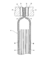
- FIG. 2 is an enlarged cross-sectional explanatory view taken along the line AA in FIG. 1, showing a main part of a heat welding apparatus as a first embodiment of a laminated secondary battery manufacturing apparatus according to the present invention.
- FIGS. 1 to 6 show a more specific first embodiment for carrying out a laminated secondary battery manufacturing apparatus according to the present invention.
- FIG. 1 shows a lithium ion secondary battery as an example of a laminated secondary battery.
- FIG. 2 shows an exploded perspective view of the schematic structure (hereinafter simply referred to as “battery”). This battery is used, for example, as a unit cell or a single battery of a lithium ion battery for an electric vehicle.
- a lead terminal (positive electrode terminal portion) 2 as a positive electrode terminal and a lead terminal (negative electrode portion) 3 as a negative electrode terminal are led out to the outside.
- a rectangular laminate film outer package 4 composed of two upper and lower laminate films 4a and 4b as an outer film.
- an electrolyte Inside the laminate film outer package 4 is accommodated together with an electrolyte a laminate 5 formed by laminating a plurality of sets of positive and negative electrodes as electrodes that are battery elements (power generation elements) and separators interposed therebetween.
- the four circumferences of the laminate film outer package 4 are hermetically sealed or sealed by heat welding.
- the four-round heat welded portion is denoted by reference numeral 6.
- a battery element including a positive electrode and a negative electrode as electrodes, a separator, and an electrolyte solution is surrounded by a laminate film outer package 4, and each positive electrode and negative electrode current collector is enclosed.
- the lead terminals 2 and 3 that are electrically connected are led out to the outside of the laminate film outer package 4, and the periphery of the laminate film outer package 4 is sealed or sealed in a rectangular bag shape by heat welding, for example. As a result, the airtightness of the battery 1 is secured.
- the two upper and lower laminate films 4a and 4b forming the laminate film outer package 4 for example, a composite structure in which both front and back surfaces of an aluminum foil are covered with a heat-welding resin film is used.
- both the lead terminals 2 and 3 are sometimes referred to as electrode tabs, and the positive lead terminal 2 is made of aluminum, for example, while the negative lead terminal 3 is Aluminum or copper is used.
- both lead terminals 2 and 3 are subjected to a predetermined surface treatment in advance, and are covered with a resin layer 7 (see FIG. 3) having heat welding properties and insulation properties.
- the four sides of the rectangular laminate film outer package 4 are welded in several steps, for example, by a heat welding device as a battery 1 manufacturing device, and enlarged along the line AA in FIG.
- a cross-sectional view is shown in FIG. 4 and 5 are enlarged sectional views taken along lines BB and CC in FIG.
- the thermal welding apparatus is mainly composed of a lower thermal welding jig 9 and an upper thermal welding jig 10 which are opposed to each other so as to be close to and away from each other.
- Both of the heat welding jigs 9 and 10 are made of, for example, stainless steel, and a portion that performs heat welding extends in the longitudinal direction of the heat welding portion 6 (see FIG. 1) of the laminate film exterior body 4 in a plan view. 4 and 5, the width dimension is set to be slightly larger than the width dimension of the heat-welded portion 6 of the laminate film outer package 4.
- the portions that are in contact with the upper and lower laminate films 4 a and 4 b to be the laminated film exterior body 4 to perform thermal welding that is, the lower thermal welding jig 9.
- Impulse-type and ribbon-like heaters 11 and 12 are attached to the upper surface and the lower surface of the upper heat welding jig 10 in the longitudinal direction. More specifically, as shown in an enlarged view in FIGS. 4 and 5, a ribbon-like shape is formed on the lower and upper heat welding jigs 9 and 10 through a glass tape 13 having electrical insulation and heat resistance.
- the heaters 11 and 12 are affixed, and the surfaces of the heaters 11 and 12 are covered with a heat-resistant fluororesin tape 14 to prevent the laminate films 4a and 4b from adhering.
- a portion corresponding to each of the lead terminals 2 and 3 and the other portion of the heat-welded portion 6 of the laminate film exterior body 4, that is, the laminate film exterior body 4 is configured.
- the thickness is different from the portion to be formed.
- the lead terminals between the upper and lower laminate films 4a and 4b of the respective heaters 11 and 12 attached to the upper and lower heat welding jigs 9 and 10 are provided.
- the thickness of the heaters 11 and 12 (see t1 in FIG. 6) is small at the portion where the heat welding is performed with 2 and 3 interposed, and conversely, the upper and lower laminate films 4a and 4b are not interposed between the lead terminals 2 and 3.
- the thickness of the heaters 11 and 12 is made different for each portion of the heat-welded portion 6 so that the thickness of the heaters 11 and 12 (see t2 in FIG. 6) is increased at the portion where the heat-welded portions are directly heat-welded.
- the impulse-type and ribbon-shaped heaters 11 and 12 described above are welded by instantaneously flowing low voltage and high current to generate heat, and heating and melting the laminate films 4a and 4b as objects. Therefore, after the energization is completed, the pressure is maintained for a predetermined time and the cooling is performed.
- the two laminate films 4a and 4b are supported by a support member (not shown), and the portions to be thermally welded of these laminate films 4a and 4b are positioned with respect to the upper and lower heat welding jigs 9 and 10.
- the lower heat welding jig 9 and the upper heat welding jig 9 Together with the jig 10, the upper and lower laminate films 4 a and 4 b are pressed and restrained from above and below as shown in FIGS. 4 and 5 in addition to FIG. 3. And in this pressure restraint state, impulse welding is applied to the heaters 11 and 12 to perform heat welding.
- FIG. 6 schematically shows the relationship between the heat welding portion 6 of FIGS. 1 and 3 and the impulse-type upper and lower heaters 111 and 2 in an easy-to-understand manner.
- a portion of the heaters 11 and 12 corresponding to the lead terminals 2 and 3 of the heat welding portion 6 (hereinafter, this portion is referred to as a “lead terminal 2 and 3 corresponding portion”).
- the thickness t1 is relatively small, while the thickness t2 of the heaters 11 and 12 other than the portions corresponding to the lead terminals 2 and 3 of the heat welding portion 6 is relatively large. I mentioned earlier.
- the welding temperature at the portion corresponding to the lead terminals 2 and 3 in the heat welding portion 6 is made relatively higher than that of other portions. Therefore, it is possible to suppress or prevent the occurrence of poor welding such as insufficient welding strength at the welded portion in the corresponding portion of the lead terminals 2 and 3.
- the thickness t of the heaters 111 and 112 is constant regardless of whether the impulse-type and ribbon-shaped heaters 111 and 112 correspond to the lead terminals 2 and 3 or other portions.
- An example of the case is shown in FIG.
- the thickness t of the heaters 111 and 112 is the same regardless of whether the heaters 111 and 112 correspond to the lead terminals 2 and 3 or other portions. Since the electric resistance R C of each part is the same, the heat capacity of the lead terminals 2 and 3 in the part corresponding to the lead terminals 2 and 3 in the heat weld part 6 is large. Among them, the temperature corresponding to the lead terminals 2 and 3 is relatively low. As a result, the intended purpose as in the first embodiment cannot be achieved.
- FIG. 8 is a view showing a second embodiment of the manufacturing apparatus according to the present invention, and shows the structure of the same portion as FIG. In addition, the same code
- the thickness t of the heaters 21 and 22 is the impulse type and ribbon-shaped heaters 21 and 22 regardless of whether they are portions corresponding to the lead terminals 2 and 3 or other portions. Assuming that is constant, the portion other than the corresponding portion of the lead terminals 2 and 3, that is, the portion corresponding to the portion where the two upper and lower laminate films 4a and 4b of the heaters 21 and 22 are directly heat welded, A bent portion 15 as an extension portion is formed.
- heat welding is performed on portions other than the portions corresponding to the lead terminals 2 and 3 of the impulse-type and ribbon-shaped heaters 21 and 22 attached to the upper and lower heat welding jigs 9 and 10 of FIG.
- the bent portion 15 as an extended portion is bent at a right angle from the edge of the portion to be a contact surface with the laminate films 4a and 4b. It is.
- the bent portion 15 is intended to increase a local volume or a cross-sectional area as the heaters 21 and 22 at the corresponding portion. Therefore, the bent portion 15 is not directly used for heat welding of the laminate films 4a and 4b. Not involved.
- the portion where the bent portion 15 is not attached that is, the portion corresponding to the lead terminals 2 and 3 has a large electric resistance RH
- the portion of the heaters 21 and 22 where the bent portion 15 is attached ie, the lead terminal 2 and 2. 3
- the electric resistance R L is small in the portion other than the corresponding portion, and as a result, the portion where the bent portion 15 is not attached (the portion of the electric resistance RH ) of the heaters 21 and 22 is attached to the bent portion 15.
- the Joule heat due to Joule heat generation is higher than that of the portion where the electric resistance R L is present.
- the bent portion 15 attached to the portions other than the portions corresponding to the lead terminals 2 and 3 of the heaters 21 and 22 is not directly involved in the thermal welding between the laminate films 4a and 4b as described above. Since it is a part of the heaters 21 and 22, heat is generated in the same manner as other parts when energized. On the other hand, the bent portion 15 is only exposed to the outside without being in contact with the laminate films 4a and 4b to be thermally welded. It can contribute to improvement.
- the impulse-type and ribbon-shaped heaters 11, 12 and 21, 22 correspond to the lead terminals 2 and 3 corresponding portions.
- the electrical resistance (R H ) is large and the electrical resistance (R L ) other than the portion corresponding to the lead terminals 2 and 3 is small.
- the electrical resistance R [ ⁇ ] of the conductor is expressed by the following equation (1), where ⁇ is the electrical resistivity, L [m] is the length of the conductor, and A [m 2 ] is the cross-sectional area of the conductor.
- the conductor material is made different for each part to form a composite structure, and the electric resistance of the heater corresponding to the lead terminals 2 and 3 is set. If the material combination is such that the rate ⁇ is smaller than the electrical resistivity ⁇ of the portion other than the portion corresponding to the lead terminals 2 and 3, the same effect as in the first and second embodiments is expected. It will be possible.
- this combined structure heater it is necessary to attach the bent portion 15 (FIG. 8) if the thickness of the heater does not have to be different for each part as in the first and second embodiments.
- the shape of the heater can be simplified, and it is advantageous in terms of space efficiency.
- the impulse type heater has been described as an example.
- the heater is not limited as long as the heater is heated by Joule heat generation such as a resistance welding machine.
Landscapes
- Chemical & Material Sciences (AREA)
- Chemical Kinetics & Catalysis (AREA)
- Electrochemistry (AREA)
- General Chemical & Material Sciences (AREA)
- Engineering & Computer Science (AREA)
- Manufacturing & Machinery (AREA)
- Connection Of Batteries Or Terminals (AREA)
- Sealing Battery Cases Or Jackets (AREA)
Abstract
電極を含む電池要素をラミネートフィルム外装体(4)に収納し、リード端子(2),(3)を外装体(4)の外部に導出させた上で、ラミネートフィルム外装体(4)となるべき上下のラミネートフィルム(4a),(4b)の周縁部を熱溶着により封止する装置である。ラミネートフィルム(4a),(4b)との接触面側にインパルス式のヒータ(11),(12)を備えた熱溶着治具(9),(10)によりラミネートフィルム(4a),(4b)を加圧拘束して熱溶着を施すにあたり、ヒータ(11),(12)のうちリード端子(2),(3)に対応する部分の電気抵抗値を当該リード端子(2),(3)対応部分以外の部分の電気抵抗値よりも大きく設定してある。このように、リード端子(2),(3)に対応する部分での溶着温度を相対的に高くすることで当該部分での熱溶着不良の発生を抑制できる。
Description
本発明は、ラミネート型または薄型と称される二次電池の製造装置と製造方法に関する。
リチウムイオン二次電池に代表されるようなラミネートパック型(薄型)の二次電池にあっては、電極である正極や負極および電解液を含む電池要素(発電要素)を外装体となるラミネートタイプの外装フィルムで包囲し、正極および負極の各集電体に電気的に接続されたリード端子を外装フィルムの外部に導出させた上で、外装フィルムの周縁部を熱溶着により例えば矩形袋状に封止または封口処理を施し、もって電池としての気密性を確保して、内部の電解液の漏れ出しを防ぐ構造となっている。なお、上記外装フィルムとしては、例えばアルミニウム箔の表裏両面を樹脂フィルムで被覆した構造のものが用いられる。
そして、外装フィルムに熱溶着を施す具体的手段としては、例えば特許文献1に記載されているように、高周波方式または熱ブロック方式(熱板方式)と称されるものが広く採用されている。
上記のような二次電池の外装フィルムの熱溶着に際して、電極のリード端子が導出している辺部に着目した場合、電極のリード端子が導出している部分では外装フィルムと金属製のリード端子とが熱溶着することになるのに対して、それ以外の部分では外装フィルム同士が熱溶着することになり、両者で熱移動の挙動が異なるため、単に加熱されている治具を押し付けただけではリード端子部分で溶着強度が低くなって熱溶着不良または封止不良が発生しやすい。これは、リード端子が導出している部分では、熱溶着のための熱がリード端子そのものに余分に移動してしまい、実際に溶着にあずかる部分の温度が低下してしまうことが原因と考えられる。
本発明はこのような課題に着目してなされたものであり、とりわけ外装フィルムのうちリード端子が導出している辺部に熱溶着を施すに際して、リード端子に対応する部分での溶着温度を相対的に高くすることで当該リード端子対応部分での熱溶着不良の発生を抑制しようとするものである。
本発明に係るラミネート型二次電池の製造装置および製造方法では、外装フィルムとの接触面側にジュール発熱によって加熱するヒータを備えた熱溶着治具により外装フィルムの周縁部を加圧拘束して熱溶着処理を施すようにあたって、上記ヒータのうち電極の端子部に対応する部分の電気抵抗値を当該端子部対応部分以外の部分の電気抵抗値よりも大きく設定しておくこととしたものである。
本発明によれば、ジュール発熱によって加熱するヒータのうち電極の端子部に対応する部分の電気抵抗値を当該端子部対応部分以外の部分の電気抵抗値よりも大きく設定しておくことで、一定の電流が流れたときのジュール発熱が端子部対応部分の方が相対的に大きく、端子部対応部分での溶着部の温度を端子部対応部分以外の部分のそれよりも高くすることができる。そのため、端子部対応部分における溶着部での溶着強度不足等の溶着不良の発生を抑制することができる。
図1~6は本発明に係るラミネート型二次電池の製造装置を実施するためのより具体的な第1の形態を示し、特に図1はラミネート型二次電池の一例としてリチウムイオン二次電池(以下、単に「電池」という。)の概略構造を、図2はその分解斜視図をそれぞれ示している。この電池は、例えば電気自動車用のリチウムイオンバッテリの単位セルまたは単電池として用いられる。
図1,2に示すように、電池1は、正極側の電極端子としてのリード端子(正極端子部)2と負極側の電極端子としてのリード端子(負極端子部)3とが外部に導出された状態で外装フィルムとしての上下二枚のラミネートフィルム4a,4bからなる矩形状のラミネートフィルム外装体4にてパッキングされている。ラミネートフィルム外装体4の内部には、電池要素(発電要素)である電極としての正極と負極およびそれら両者の間に介在するセパレータとを複数組積層してなる積層体5が電解液とともに収容されていて、ラミネートフィルム外装体4の四周が熱溶着により気密に封止または封口処理が施されている。なお、四周の熱溶着部を符号6で示す。
すなわち、図1,2に示した電池1にあっては、電極である正極や負極、セパレータおよび電解液を含む電池要素をラミネートフィルム外装体4で包囲し、正極および負極の各集電体に電気的に接続されたそれぞれのリード端子2,3をラミネートフィルム外装体4の外部に導出させた上で、ラミネートフィルム外装体4の周縁部を熱溶着により例えば矩形袋状に封止または封口処理を施すことで、電池1としての気密性を確保してある。なお、ラミネートフィルム外装体4を形成している上下二枚のラミネートフィルム4a,4bとしては、例えばアルミニウム箔の表裏両面を熱溶着性樹脂フィルムで被覆した複合構造のものが使用される。
そして、矩形状のラミネートフィルム外装体4のうち共通の一辺部から正極側のリード端子2と負極側のリード端子3とが共に外部に導出されている。この場合において、双方のリード端子2,3は電極タブと称されることがあるほか、正極側のリード端子2としては例えばアルミニウム製のものが使用され、他方、負極側のリード端子3としてはアルミニウムまたは銅製のものが使用される。また、双方のリード端子2,3は予め所定の表面処理が施された上で、熱溶着性および絶縁性のある樹脂層7(図3参照)で被覆されている。
矩形状のラミネートフィルム外装体4における四辺部の熱溶着は電池1の製造装置としての熱溶着装置により例えば数工程に分けて行われ、熱溶着時における図1のA-A線に沿った拡大断面図を図3に示している。また、図3のB-B線およびC-C線に沿ったそれぞれの拡大断面図を図4,5に示している。
図4,5から明らかなように、図2の積層体5の一部を形成している複数枚の正極8の延長部同士を重ね合わせた上で、当該重合部8aを正極8側のリード端子2に溶接にて接続してある。なお、この構造は負極とその負極側のリード端子3との関係についても基本的に同様であり、これらの構造は図2では図示省略している。
図3に示すように、熱溶着装置は、互いに接近離間可能に対向配置された下側の熱溶着治具9と上側の熱溶着治具10とを主要素として構成されている。双方の熱溶着治具9,10は例えばステンレス製のものであり、熱溶着を司る部分が平面視ではラミネートフィルム外装体4の熱溶着部6(図1参照)の長手方向に延び、且つ図4,5に示すように幅寸法がラミネートフィルム外装体4の熱溶着部6の幅寸法よりもわずかに大きい寸法に設定されている。
そして、図2の積層体5を包囲するラミネートフィルム外装体4となるべき上下二枚のラミネートフィルム4a,4bを図示外の支持部材で支えた状態で、図3に示すように、下側の熱溶着治具9と上側の熱溶着治具10とを接近動作させて、上下二枚のラミネートフィルム4a,4bを上下から加圧拘束することで該当部位に熱溶着を施し、もってラミネートフィルム外装体4として仕上げられることになる。
下側および上側の熱溶着治具9,10のうちラミネートフィルム外装体4となるべき上下二枚のラミネートフィルム4a,4bと接触して熱溶着を司る部分、すなわち下側の熱溶着治具9の上面および上側の熱溶着治具10の下面には、それぞれにインパルス式で且つリボン状のヒータ11,12を長手方向に沿って貼り付けてある。より具体的には、図4,5に拡大して示すように、下側および上側の熱溶着治具9,10に対して電気絶縁性および耐熱性のあるガラステープ13を介してリボン状のヒータ11,12を貼り付け、さらにヒータ11,12の表面にはラミネートフィルム4a,4bの貼り付き防止のために耐熱性のあるフッ素樹脂製のテープ14を貼り付けて被覆してある。
そして、図3から明らかなように、ラミネートフィルム外装体4の熱溶着部6のうちリード端子2,3にそれぞれ対応する部分とそれ以外の部分、すなわちラミネートフィルム外装体4を構成することになる上下のラミネートフィルム4a,4b同士の間にリード端子2,3が介在した状態で熱溶着される部分と、リード端子2,3が介在することなく上下のラミネートフィルム4a,4b同士が直接熱溶着される部分とでは、その厚みが異なっている。
この熱溶着部6の厚みの違いに対応するために、上下の熱溶着治具9,10に貼り付けられたそれぞれのヒータ11,12について、上下のラミネートフィルム4a,4b同士の間にリード端子2,3が介在した状態で熱溶着される部分ではヒータ11,12の厚み(図6のt1参照)が小さく、逆にリード端子2,3が介在することなく上下のラミネートフィルム4a,4b同士が直接熱溶着される部分ではヒータ11,12の厚み(図6のt2参照)が大きくなるようにして、熱溶着部6の部位ごとにヒータ11,12の厚みを異ならせてある。
なお、先に述べたインパルス式で且つリボン状のヒータ11,12は、瞬間的に低電圧・高電流を流して発熱させ、対象物であるラミネートフィルム4a,4bを加熱・溶融させることで溶着するものであり、通電完了後も所定時間だけ加圧状態のままとして冷却させることになる。
したがって、このように構成された熱溶着装置では、上下の熱溶着治具9,10が相互に離間している状態で、図2の積層体5を包囲するラミネートフィルム外装体4となるべき上下二枚のラミネートフィルム4a,4bを図示外の支持部材で支えて、これらのラミネートフィルム4a,4bのうち熱溶着対象部位を上下の熱溶着治具9,10に対して位置決めする。
ラミネートフィルム外装体4となるべき上下二枚のラミネートフィルム4a,4bと上下の熱溶着治具9,10との相対位置決めがなされたならば、下側の熱溶着治具9と上側の熱溶着治具10とを共に接近動作させて、図3のほか図4,5に示すように上下二枚のラミネートフィルム4a,4bを上下から加圧拘束する。そして、この加圧拘束状態のままでそれぞれのヒータ11,12にインパルス通電して熱溶着を施すことになる。
ここで、図1,3の熱溶着部6とインパルス式で且つリボン状の上下のヒータ111,2との関係をわかりやすく模式化したものを図6に示す。図3~5のほか図6にも示すように、ヒータ11,12のうち熱溶着部6のリード端子2,3に対応する部分(以下、当該部位を「リード端子2,3対応部分」と称する。)ではその厚みt1が相対的に小さく、他方、ヒータ11,12のうち熱溶着部6のリード端子2,3対応部分以外の部分ではその厚みt2が相対的に大きくなっていることは先に述べた。そのため、ヒータ11,12に一定の電流を流した場合に、ヒータ11,12のうち厚みt1の部分では電気抵抗RHが大きく、逆にヒータ11,12のうち厚みt2の部分では電気抵抗RLが小さくなり、結果としてヒータ11,12のうち厚みt1の部分(電気抵抗RHの部分)の方が厚みt2の部分(電気抵抗RLの部分)よりもジュール発熱によるジュール熱が高いものとなる。
このことは、熱溶着部6のうち上下二枚のラミネートフィルム4a,4b同士が直接熱溶着される部分に比べ、リード端子2,3対応部分、すなわち上下二枚のラミネートフィルム4a,4b同士の間にリード端子2,3が挾まれていてそれらのラミネートフィルム4a,4bとリード端子2,3とが熱溶着される部分での発熱量が大きいことを意味する。これにより、リード端子2,3対応部分以外の部分とは異なり、リード端子2,3対応部分ではラミネートフィルム4a,4b同士の間に樹脂層7(図3参照)が介在していて、しかも熱溶着時に一部の熱が熱容量の大きなリード端子2,3そのものに逃げたとしても、熱溶着部6のうちリード端子2,3対応部分での溶着温度を他の部位よりも相対的に高くすることができて、当該リード端子2,3対応部分における溶着部での溶着強度不足等の溶着不良の発生を抑制または未然に防止することができる。
ここで、参考までに、インパルス式で且つリボン状のヒータ111,112のうちリード端子2,3対応部分であるかそれ以外の部分であるかにかかわらず、ヒータ111,112の厚みtを一定にした場合の例を図7に示す。この場合には、同図から明らかなように、ヒータ111,112のうちリード端子2,3対応部分であるかそれ以外の部分であるかにかかわらず、共にヒータ111,112としての厚みtが一定していて、しかも各部の電気抵抗RCも同じであるため、熱溶着部6のうちリード端子2,3対応部分ではそのリード端子2,3そのものの熱容量が大きいために、熱溶着部6のうちリード端子2,3対応部分での温度が相対的に低いものとなる。その結果、先の第1の実施の形態のような所期の目的を達成することはできなくなる。
図8は本発明に係る製造装置の第2の実施の形態を示す図で、図6と同等部分の構造を示している。なお、図6と共通する部分には同一符号を付してある。
この第2の実施の形態では、インパルス式で且つリボン状のヒータ21,22のうちリード端子2,3対応部分であるかそれ以外の部分であるかにかかわらず、ヒータ21,22の厚みtが一定であることを前提に、リード端子2,3対応部分以外の部分、すなわちヒータ21,22のうち上下二枚のラミネートフィルム4a,4b同士が直接熱溶着される部分に対応する部分に、延長部たる屈曲部15を形成したものである。
図8に示すように、図3の上下の熱溶着治具9,10に貼り付けられるインパルス式で且つリボン状のヒータ21,22のうちリード端子2,3対応部分以外の部分において、熱溶着時の障害とならないように、ヒータ21,22の幅寸法を局部的に広げるべく、ラミネートフィルム4a,4bとの接触面となる部位の端縁から直角に延長部としての屈曲部15を折り曲げ形成してある。この屈曲部15は該当部位でのヒータ21,22としての局部的な容積または断面積の増大化を意図したものであり、よって屈曲部15はラミネートフィルム4a,4b同士の熱溶着には直接は関与しない。
この第2の実施の形態では、先に説明した図6の第1の実施の形態と同様に、厚みtが均一なヒータ21,22に一定の電流を流した場合に、ヒータ21,22のうち屈曲部15が付帯していない部分、すなわちリード端子2,3対応部分では電気抵抗RHが大きく、逆にヒータ21,22のうち屈曲部15が付帯している部分、すなわちリード端子2,3対応部分以外の部分では電気抵抗RLが小さくなり、結果としてヒータ21,22のうち屈曲部15が付帯していない部分(電気抵抗RHの部分)の方が屈曲部15が付帯している部分(電気抵抗RLの部分)よりもジュール発熱によるジュール熱が高いものとなる。
このことは、先の第1の実施の形態と同様に、熱溶着部6のうち上下二枚のラミネートフィルム4a,4b同士が直接熱溶着される部分に比べ、リード端子2,3対応部分、すなわち上下二枚のラミネートフィルム4a,4b同士の間にリード端子2,3が挾まれていてそれらのラミネートフィルム4a,4bとリード端子2,3とが熱溶着される部分での発熱量が大きいことを意味する。これにより、熱溶着時に一部の熱が熱容量の大きなリード端子2,3そのものに逃げたとしても、熱溶着部6のうちリード端子2,3対応部分での溶着温度を他の部位よりも相対的に高くすることができて、当該リード端子2,3対応部分における溶着部での溶着強度不足等の溶着不良の発生を抑制または未然に防止することができる。
また、ヒータ21,22のうちリード端子2,3対応部分以外の部分に付帯している屈曲部15は、先に述べたようにラミネートフィルム4a,4b同士の熱溶着には直接は関与しないものの、ヒータ21,22の一部であることには変わりはないので、通電時には他の部位と同様に発熱することになる。その一方で、屈曲部15は熱溶着対象であるラミネートフィルム4a,4bには接することなく外部に露出しているだけであるので、例えばヒータ21,22への通電を断った後の放熱性の向上には寄与することができる。
ここで、図6,8に示した第1,第2の実施の形態から明らかなように、インパルス式で且つリボン状のヒータ11,12および21,22のうちリード端子2,3対応部分の電気抵抗(RH)が大きく、リード端子2,3対応部分以外の電気抵抗(RL)が小さいことは先に述べたとおりである。導体の電気抵抗R[Ω]は、電気抵抗率をρ、導体の長さをL[m]、導体の断面積をA[m2]とすると次の式(1)で表される。
R=ρ(L/A)[Ω]‥‥(1)
すなわち、電気抵抗率ρは次の式(2)で表される。
すなわち、電気抵抗率ρは次の式(2)で表される。
ρ=RA/L[Ω・m]‥‥(2)
そうすると、ヒータ11,12および21,22のうちリード端子2,3対応部分の電気抵抗(RH)が大きく、リード端子2,3対応部分以外の電気抵抗(RL)が小さいことは、ヒータ11,12および21,22のうちリード端子2,3対応部分の電気抵抗率ρがリード端子2,3対応部分以外の部分の電気抵抗率ρよりも小さいことにほかならない。
そうすると、ヒータ11,12および21,22のうちリード端子2,3対応部分の電気抵抗(RH)が大きく、リード端子2,3対応部分以外の電気抵抗(RL)が小さいことは、ヒータ11,12および21,22のうちリード端子2,3対応部分の電気抵抗率ρがリード端子2,3対応部分以外の部分の電気抵抗率ρよりも小さいことにほかならない。
そこで、インパルス式で且つリボン状のヒータについて、厚みtが均一であることを前提に、部位毎に導体の材質を異ならせて複合構造とし、ヒータのうちリード端子2,3対応部分の電気抵抗率ρがリード端子2,3対応部分以外の部分の電気抵抗率ρよりも小さくなるような材質の組み合わせとすれば、先の第1,第2の実施の形態のものと同様の効果が期待できることになる。そして、この複合構造のヒータを採用した場合には、第1,第2の実施の形態のようにヒータの厚みを部位毎に異ならせる必要もなければ屈曲部15(図8)を付帯させる必要もなく、ヒータの形状を単純化できるとともに、スペース効率的にも有利となる。
なお、上記各実施の形態ではインパルス式のヒータを事例に説明したが、抵抗溶接機などジュール発熱によって加熱するヒータであれば、その限りではない。
Claims (6)
- 電極を含む電池要素を外装フィルムに収納し、電極の端子部を外装フィルムの外部に導出させた上で外装フィルムの周縁部を熱溶着により封止するようにしたラミネート型二次電池の製造装置において、
上記外装フィルムとの接触面側にジュール発熱によって加熱するヒータを備えた熱溶着治具により外装フィルムの周縁部を加圧拘束して熱溶着処理を施すようになっていて、
上記ヒータのうち電極の端子部に対応する部分の電気抵抗値を当該端子部対応部分以外の部分の電気抵抗値よりも大きく設定してあるラミネート型二次電池の製造装置。 - 上記ヒータはリボン状のものであって、
このリボン状のヒータは、電極の端子部に対応する部分であるか当該端子部対応部分以外の部分であるかにかかわらず均一厚みのものであり、
上記ヒータのうち端子部対応部分以外の部分であって且つ外装フィルムとの接触面以外の部分に延長部を設けてある請求項1に記載のラミネート型二次電池の製造装置。 - 上記延長部は外装フィルムとの接触面の端部から直角に折り曲げた屈曲部である請求項2に記載のラミネート型二次電池の製造装置。
- 上記ヒータはリボン状のものであって、
このリボン状のヒータは、電極の端子部に対応する部分の厚みよりも当該端子部対応部分以外の部分の厚みの方が大きくなるように設定してある請求項1に記載のラミネート型二次電池の製造装置。 - 上記ヒータはリボン状のものであって、
このリボン状のヒータは、電極の端子部に対応する部分の電気抵抗率の方が当該端子部対応部分以外の部分の電気抵抗率よりも低くなるように設定してある請求項1に記載のラミネート型二次電池の製造装置。 - 電極を含む電池要素を外装フィルムに収納し、電極の端子部を外装フィルムの外部に導出させた上で外装フィルムの周縁部を熱溶着により封止するようにしたラミネート型二次電池の製造方法において、
上記外装フィルムとの接触面側にジュール発熱によって加熱するヒータを備えた熱溶着治具により外装フィルムの周縁部を加圧拘束して熱溶着処理を施すにあたり、
上記ヒータのうち電極の端子部に対応する部分の電気抵抗値を当該端子部対応部分以外の部分の電気抵抗値よりも大きくした状態で熱溶着処理を施すものであるラミネート型二次電池の製造方法。
Applications Claiming Priority (2)
| Application Number | Priority Date | Filing Date | Title |
|---|---|---|---|
| JP2013096146 | 2013-05-01 | ||
| JP2013-096146 | 2013-05-01 |
Publications (1)
| Publication Number | Publication Date |
|---|---|
| WO2014178238A1 true WO2014178238A1 (ja) | 2014-11-06 |
Family
ID=51843373
Family Applications (1)
| Application Number | Title | Priority Date | Filing Date |
|---|---|---|---|
| PCT/JP2014/057220 WO2014178238A1 (ja) | 2013-05-01 | 2014-03-18 | ラミネート型二次電池の製造装置および製造方法 |
Country Status (1)
| Country | Link |
|---|---|
| WO (1) | WO2014178238A1 (ja) |
Cited By (2)
| Publication number | Priority date | Publication date | Assignee | Title |
|---|---|---|---|---|
| JP2021082448A (ja) * | 2019-11-18 | 2021-05-27 | トヨタ自動車株式会社 | 電池の製造方法 |
| CN113224425A (zh) * | 2020-02-04 | 2021-08-06 | 丰田自动车株式会社 | 层压电池及其制造方法 |
Citations (5)
| Publication number | Priority date | Publication date | Assignee | Title |
|---|---|---|---|---|
| JP2002190283A (ja) * | 2000-12-21 | 2002-07-05 | At Battery:Kk | 薄型二次電池の製造方法および薄型二次電池 |
| JP2003331798A (ja) * | 2002-05-15 | 2003-11-21 | Toyota Motor Corp | 電極体を封止する外装材フィルムおよび外装材フィルムのシール方法 |
| JP2005056815A (ja) * | 2003-07-22 | 2005-03-03 | Toyota Motor Corp | 二次電池及びその作製方法 |
| JP2005116228A (ja) * | 2003-10-03 | 2005-04-28 | Nec Lamilion Energy Ltd | ラミネートフィルムの熱融着方法、フィルム外装電池の製造方法およびラミネートフィルム用熱融着装置 |
| JP2014032924A (ja) * | 2012-08-06 | 2014-02-20 | Nec Energy Devices Ltd | フィルム外装電池およびその製造方法 |
-
2014
- 2014-03-18 WO PCT/JP2014/057220 patent/WO2014178238A1/ja active Application Filing
Patent Citations (5)
| Publication number | Priority date | Publication date | Assignee | Title |
|---|---|---|---|---|
| JP2002190283A (ja) * | 2000-12-21 | 2002-07-05 | At Battery:Kk | 薄型二次電池の製造方法および薄型二次電池 |
| JP2003331798A (ja) * | 2002-05-15 | 2003-11-21 | Toyota Motor Corp | 電極体を封止する外装材フィルムおよび外装材フィルムのシール方法 |
| JP2005056815A (ja) * | 2003-07-22 | 2005-03-03 | Toyota Motor Corp | 二次電池及びその作製方法 |
| JP2005116228A (ja) * | 2003-10-03 | 2005-04-28 | Nec Lamilion Energy Ltd | ラミネートフィルムの熱融着方法、フィルム外装電池の製造方法およびラミネートフィルム用熱融着装置 |
| JP2014032924A (ja) * | 2012-08-06 | 2014-02-20 | Nec Energy Devices Ltd | フィルム外装電池およびその製造方法 |
Cited By (3)
| Publication number | Priority date | Publication date | Assignee | Title |
|---|---|---|---|---|
| JP2021082448A (ja) * | 2019-11-18 | 2021-05-27 | トヨタ自動車株式会社 | 電池の製造方法 |
| JP7333000B2 (ja) | 2019-11-18 | 2023-08-24 | トヨタ自動車株式会社 | 電池の製造方法 |
| CN113224425A (zh) * | 2020-02-04 | 2021-08-06 | 丰田自动车株式会社 | 层压电池及其制造方法 |
Similar Documents
| Publication | Publication Date | Title |
|---|---|---|
| JP6019224B2 (ja) | ラミネート型二次電池の製造方法および製造装置 | |
| KR102042018B1 (ko) | 실링 라인이 형성되어 있는 외주면 실링부를 포함하는 전지셀, 및 이를 생산하기 위한 전지셀 실링장치 | |
| JP5224658B2 (ja) | シールフィルム付きリード線部材の製造方法 | |
| JP6678768B2 (ja) | フィルム外装電池の製造方法およびフィルム外装電池 | |
| JP6004112B2 (ja) | ラミネート型蓄電デバイスの製造方法 | |
| JP2014032924A (ja) | フィルム外装電池およびその製造方法 | |
| JP2013502672A (ja) | フレームを備えるガルバニ電池及びこれを製造する方法 | |
| JP5028986B2 (ja) | 薄型電池、薄型電池の製造方法および製造装置 | |
| JP5876380B2 (ja) | 積層アルミニウム材の製造方法及びそれを含む密閉型電池の製造方法 | |
| JP2014018810A (ja) | 抵抗溶接装置、及びそれを用いた抵抗溶接方法 | |
| WO2014178238A1 (ja) | ラミネート型二次電池の製造装置および製造方法 | |
| JP6862639B2 (ja) | ヒートブロック | |
| JP5558878B2 (ja) | 組電池、抵抗溶接方法および組電池の製造方法 | |
| CN104051679B (zh) | 电化学电池以及电化学电池的制造方法 | |
| JP6020920B2 (ja) | 蓄電素子 | |
| JP6318577B2 (ja) | シール部品の製造装置及び製造方法 | |
| JP2013166287A (ja) | 熱融着装置及び熱融着方法 | |
| JP2015205419A (ja) | ヒートシーラー及びその製造方法 | |
| JP4108184B2 (ja) | 薄型温度ヒュ−ズの製造方法 | |
| JP2018120803A (ja) | フィルム外装電池の製造方法およびフィルム外装電池 | |
| WO2011068086A1 (ja) | 蓄電装置及び蓄電装置の製造方法 | |
| KR102265236B1 (ko) | 유도 가열 방식의 실링 툴을 포함하고 있는 전지셀 제조장치 | |
| JP2012175084A (ja) | 蓄電デバイス、蓄電セルの製造方法および蓄電デバイスの製造方法 | |
| JP7348119B2 (ja) | 溶接方法及び電池モジュールの製造方法 | |
| WO2015054949A1 (zh) | 电力电容器及其制造方法 |
Legal Events
| Date | Code | Title | Description |
|---|---|---|---|
| 121 | Ep: the epo has been informed by wipo that ep was designated in this application |
Ref document number: 14791979 Country of ref document: EP Kind code of ref document: A1 |
|
| NENP | Non-entry into the national phase |
Ref country code: DE |
|
| 122 | Ep: pct application non-entry in european phase |
Ref document number: 14791979 Country of ref document: EP Kind code of ref document: A1 |
|
| NENP | Non-entry into the national phase |
Ref country code: JP |