WO2014175455A1 - 電子機器 - Google Patents
電子機器 Download PDFInfo
- Publication number
- WO2014175455A1 WO2014175455A1 PCT/JP2014/061797 JP2014061797W WO2014175455A1 WO 2014175455 A1 WO2014175455 A1 WO 2014175455A1 JP 2014061797 W JP2014061797 W JP 2014061797W WO 2014175455 A1 WO2014175455 A1 WO 2014175455A1
- Authority
- WO
- WIPO (PCT)
- Prior art keywords
- display unit
- display
- unit
- overlap
- detection
- Prior art date
- Legal status (The legal status is an assumption and is not a legal conclusion. Google has not performed a legal analysis and makes no representation as to the accuracy of the status listed.)
- Ceased
Links
Images


Classifications
-
- G—PHYSICS
- G06—COMPUTING OR CALCULATING; COUNTING
- G06F—ELECTRIC DIGITAL DATA PROCESSING
- G06F1/00—Details not covered by groups G06F3/00 - G06F13/00 and G06F21/00
- G06F1/16—Constructional details or arrangements
- G06F1/1613—Constructional details or arrangements for portable computers
- G06F1/1615—Constructional details or arrangements for portable computers with several enclosures having relative motions, each enclosure supporting at least one I/O or computing function
- G06F1/1616—Constructional details or arrangements for portable computers with several enclosures having relative motions, each enclosure supporting at least one I/O or computing function with folding flat displays, e.g. laptop computers or notebooks having a clamshell configuration, with body parts pivoting to an open position around an axis parallel to the plane they define in closed position
- G06F1/162—Constructional details or arrangements for portable computers with several enclosures having relative motions, each enclosure supporting at least one I/O or computing function with folding flat displays, e.g. laptop computers or notebooks having a clamshell configuration, with body parts pivoting to an open position around an axis parallel to the plane they define in closed position changing, e.g. reversing, the face orientation of the screen with a two degrees of freedom mechanism, e.g. for folding into tablet PC like position or orienting towards the direction opposite to the user to show to a second user
-
- G—PHYSICS
- G06—COMPUTING OR CALCULATING; COUNTING
- G06F—ELECTRIC DIGITAL DATA PROCESSING
- G06F1/00—Details not covered by groups G06F3/00 - G06F13/00 and G06F21/00
- G06F1/16—Constructional details or arrangements
- G06F1/1613—Constructional details or arrangements for portable computers
- G06F1/1633—Constructional details or arrangements of portable computers not specific to the type of enclosures covered by groups G06F1/1615 - G06F1/1626
- G06F1/1637—Details related to the display arrangement, including those related to the mounting of the display in the housing
- G06F1/1641—Details related to the display arrangement, including those related to the mounting of the display in the housing the display being formed by a plurality of foldable display components
-
- G—PHYSICS
- G06—COMPUTING OR CALCULATING; COUNTING
- G06F—ELECTRIC DIGITAL DATA PROCESSING
- G06F1/00—Details not covered by groups G06F3/00 - G06F13/00 and G06F21/00
- G06F1/16—Constructional details or arrangements
- G06F1/1613—Constructional details or arrangements for portable computers
- G06F1/1633—Constructional details or arrangements of portable computers not specific to the type of enclosures covered by groups G06F1/1615 - G06F1/1626
- G06F1/1637—Details related to the display arrangement, including those related to the mounting of the display in the housing
- G06F1/1647—Details related to the display arrangement, including those related to the mounting of the display in the housing including at least an additional display
-
- G—PHYSICS
- G06—COMPUTING OR CALCULATING; COUNTING
- G06F—ELECTRIC DIGITAL DATA PROCESSING
- G06F1/00—Details not covered by groups G06F3/00 - G06F13/00 and G06F21/00
- G06F1/16—Constructional details or arrangements
- G06F1/1613—Constructional details or arrangements for portable computers
- G06F1/1633—Constructional details or arrangements of portable computers not specific to the type of enclosures covered by groups G06F1/1615 - G06F1/1626
- G06F1/1675—Miscellaneous details related to the relative movement between the different enclosures or enclosure parts
- G06F1/1677—Miscellaneous details related to the relative movement between the different enclosures or enclosure parts for detecting open or closed state or particular intermediate positions assumed by movable parts of the enclosure, e.g. detection of display lid position with respect to main body in a laptop, detection of opening of the cover of battery compartment
-
- G—PHYSICS
- G06—COMPUTING OR CALCULATING; COUNTING
- G06F—ELECTRIC DIGITAL DATA PROCESSING
- G06F3/00—Input arrangements for transferring data to be processed into a form capable of being handled by the computer; Output arrangements for transferring data from processing unit to output unit, e.g. interface arrangements
- G06F3/01—Input arrangements or combined input and output arrangements for interaction between user and computer
- G06F3/048—Interaction techniques based on graphical user interfaces [GUI]
- G06F3/0481—Interaction techniques based on graphical user interfaces [GUI] based on specific properties of the displayed interaction object or a metaphor-based environment, e.g. interaction with desktop elements like windows or icons, or assisted by a cursor's changing behaviour or appearance
-
- H—ELECTRICITY
- H04—ELECTRIC COMMUNICATION TECHNIQUE
- H04M—TELEPHONIC COMMUNICATION
- H04M1/00—Substation equipment, e.g. for use by subscribers
- H04M1/02—Constructional features of telephone sets
- H04M1/0202—Portable telephone sets, e.g. cordless phones, mobile phones or bar type handsets
- H04M1/0206—Portable telephones comprising a plurality of mechanically joined movable body parts, e.g. hinged housings
- H04M1/0208—Portable telephones comprising a plurality of mechanically joined movable body parts, e.g. hinged housings characterized by the relative motions of the body parts
- H04M1/0214—Foldable telephones, i.e. with body parts pivoting to an open position around an axis parallel to the plane they define in closed position
-
- G—PHYSICS
- G06—COMPUTING OR CALCULATING; COUNTING
- G06F—ELECTRIC DIGITAL DATA PROCESSING
- G06F2203/00—Indexing scheme relating to G06F3/00 - G06F3/048
- G06F2203/048—Indexing scheme relating to G06F3/048
- G06F2203/04804—Transparency, e.g. transparent or translucent windows
-
- G—PHYSICS
- G06—COMPUTING OR CALCULATING; COUNTING
- G06F—ELECTRIC DIGITAL DATA PROCESSING
- G06F3/00—Input arrangements for transferring data to be processed into a form capable of being handled by the computer; Output arrangements for transferring data from processing unit to output unit, e.g. interface arrangements
- G06F3/14—Digital output to display device ; Cooperation and interconnection of the display device with other functional units
- G06F3/1423—Digital output to display device ; Cooperation and interconnection of the display device with other functional units controlling a plurality of local displays, e.g. CRT and flat panel display
-
- G—PHYSICS
- G09—EDUCATION; CRYPTOGRAPHY; DISPLAY; ADVERTISING; SEALS
- G09G—ARRANGEMENTS OR CIRCUITS FOR CONTROL OF INDICATING DEVICES USING STATIC MEANS TO PRESENT VARIABLE INFORMATION
- G09G2300/00—Aspects of the constitution of display devices
- G09G2300/02—Composition of display devices
- G09G2300/023—Display panel composed of stacked panels
-
- H—ELECTRICITY
- H04—ELECTRIC COMMUNICATION TECHNIQUE
- H04M—TELEPHONIC COMMUNICATION
- H04M2250/00—Details of telephonic subscriber devices
- H04M2250/16—Details of telephonic subscriber devices including more than one display unit
Definitions
- the present invention relates to an electronic device including a plurality of display units.
- An example of an electronic device is a mobile phone.
- a type of foldable mobile phone includes a transparent display so that it can be easily operated even when two housings are closed (see Patent Document 1).
- An object of the present invention is to provide an electronic device with improved user convenience.
- One aspect of the electronic apparatus of the present invention includes a first display unit, a second display unit, and a first connection unit.
- the first display unit is light transmissive.
- the first coupling unit couples the first display unit and the second display unit such that the first display unit and the second display unit transition between an open state and a closed state.
- the open state is a state where the first display unit and the second display unit do not overlap.
- the closed state is a state where the first display unit and the second display unit overlap. In the closed state in which the first display unit and the second display unit overlap, the second display unit can be visually recognized through the first display unit.
- the electronic device may further include a first detection unit.
- the first detection unit moves to overlap with at least one of the first display unit and the second display unit when the first display unit and the second display unit transition to an open state. Is possible.
- the first detection unit detects contact.
- the electronic device may further include a control unit as described below.
- the control unit controls an image displayed on the first display unit based on a detection result of the first detection unit when the first detection unit moves so as to overlap the first display unit.
- the control unit controls an image displayed on the second display unit based on a detection result of the first detection unit when the first detection unit moves so as to overlap the second display unit. .
- the electronic device may further include a control unit as described below.
- the control unit displays images related to each other on the first display unit and the second display unit, respectively, in a closed state in which the first display unit and the second display unit overlap.
- the electronic device may further include a control unit as described below.
- the control unit causes the first display unit and the second display unit to display images related to each other based on one content in a closed state in which the first display unit and the second display unit overlap each other.
- the first detection unit displays the first display unit. It may be arranged on one surface side of the part.
- the first detection unit may be disposed on the surface side of the second display unit close to the one surface of the first display unit. Good.
- the electronic device may further include a control unit as described below.
- the control unit causes the first display unit to display a parallax barrier for performing three-dimensional display when the first display unit and the second display unit transition to a closed state.
- the control unit causes the second display unit to display a three-dimensional image for performing a three-dimensional display when the first display unit and the second display unit transition to a closed state.
- the electronic device may further include a second detection unit.
- the second detection unit detects orientations of the first display unit and the second display unit.
- the control unit changes the orientation of the parallax barrier displayed on the first display unit and the three-dimensional image displayed on the second display unit based on the detection result of the second detection unit.
- the electronic device may further include a control unit as described below.
- the control unit controls to display a moving image on the first display unit.
- the control unit controls to display a still image or a character on the second display unit.
- the first display unit may be a transparent display.
- the second display unit may be electronic paper.
- the electronic apparatus may further include a control unit that causes the first display unit to display a partial image of one content in a state where the first display unit and the second display unit overlap each other.
- Another aspect of the electronic apparatus of the present invention includes a first display unit and a second display unit having transparency.
- a parallax barrier for performing three-dimensional display is displayed on the first display unit, and a three-dimensional image for performing three-dimensional display is displayed. Display on the second display unit.
- Another aspect of the electronic device includes a first display unit having light transparency, a second display unit, an open state in which the first display unit and the second display unit do not overlap, and the first display unit.
- a first connecting unit that connects the first display unit and the second display unit so as to make a transition to a closed state in which the first display unit and the second display unit overlap each other. In the closed state where the first display unit and the second display unit overlap, light emitted from the second display unit passes through the first display unit.
- an electronic device with improved user convenience can be provided.
- FIGS. 6A, 6 ⁇ / b> B, and 6 ⁇ / b> C are diagrams for explaining examples of images displayed on the first display unit and the second display unit.
- FIG. 7 is a diagram for explaining the parallax barrier method.
- FIG. 8 is a diagram for explaining a third example of the electronic apparatus.
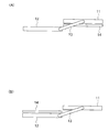
- FIG. 9A and FIG. 9B are diagrams for explaining the folding forms of the first display unit, the second display unit, and the first detection unit when the electronic apparatus is viewed from the side surface (upper surface). is there.
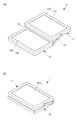
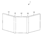
- FIG. 1 is a diagram for explaining a first example of the electronic apparatus 1.
- the electronic device 1 illustrated in FIG. 1 includes a first display unit 11, a second display unit 12, and a first connection unit 13.
- the first display unit 11 has light transmittance. That is, the first display unit 11 is a transmissive display unit. Therefore, the first display unit 11 can visually recognize the scenery from the front side to the back side, and can visually recognize the scenery from the back side to the front side.
- the first display unit 11 includes a display panel 11a, a frame body 11b (housing) that holds the display panel 11a, and the like.
- the display panel 11a of the first display unit 11 is, for example, a liquid crystal panel.
- the first display unit 11 may be a self-luminous type instead of a non-luminous type, and may be an organic EL display as an example of a self-luminous display.
- the first display unit 11 may not include the self-luminous display panel 11a. Moreover, the 1st display part 11 does not need to provide the backlight which illuminates the display panel 11a, when the non-light-emitting display panel 11a is provided. In that case, the display panel 11a of the first display unit 11 is illuminated by the light of the backlight provided on the superimposed second display unit 12, the light emitted by the second display unit 12 itself, or the ambient light, It becomes possible for the user to visually recognize the display of the 1 display unit 11. Further, the display panel 11a of the first display unit 11 may be any one of a transparent liquid crystal, a transmissive display, and a transmissive liquid crystal.
- the second display unit 12 does not have light transmittance.
- the second display unit 12 includes a display panel 12a, a housing 12b in which the display panel 12a is disposed, and the like.
- the display panel 12a of the second display unit 12 is, for example, a liquid crystal panel.
- the 2nd display part 12 is not restricted to what does not have a light transmittance, It may have a light transmittance.
- the display panel 12a of the second display unit 12 may be an organic EL display.
- the display panel 12a of the second display unit 12 may be any one of a transparent liquid crystal, a transmissive display, and a transmissive liquid crystal.
- the first connecting unit 13 is configured so that the first display unit 11 and the second display unit 12 transition to each other between an open state (see FIG. 1A) and a closed state (see FIG. 1B).
- the 1 display part 11 and the 2nd display part 12 are connected.
- the open state is a state where the first display unit 11 and the second display unit 12 do not overlap. In the open state, the first display unit 11 and the second display unit 12 can form a substantially flat surface.
- the closed state is a state in which the first display unit 11 and the second display unit 12 overlap.
- the 1st connection part 13 shown by FIG. 1 is a hinge part.
- the user can recognize that the mail text is associated with the image, and can save the trouble of checking the mail text and the image respectively.
- the text of the mail displayed on the first display unit 11 and the image attached to the mail displayed on the second display unit 12 may overlap each other when viewed from the user.
- the display panels 11a and 12a are arranged so as to overlap.
- the electronic device 1 can provide a large-screen display unit using the two display units 11 and 12.
- the electronic device 1 can provide a single screen display unit by overlapping the two display units 11 and 12.
- the electronic device 1 can share the roles of the display units 11 and 12 so that a moving image is displayed on the first display unit 11 and characters or still images are displayed on the second display unit 12.
- the electronic device 1 can display a moving image superimposed on characters or still images, various displays can be performed. Therefore, since the electronic device 1 can provide a large screen display unit and a single screen display unit, it is possible to improve user convenience.
- the first connecting portion 13 engages with the vicinity of the central portion on the side surface of the first display portion 11 and the vicinity of the end portion on the side surface of the second display portion 12.
- the user can visually recognize the second display unit 12 through the first display unit 11 in the closed state in which the first display unit 11 and the second display unit 12 overlap. Further, in the closed state where the first display unit 11 and the second display unit 12 overlap, the light emitted from the second display unit 12 is transmitted through the first display unit 11.
- the electronic device 1 can provide a large screen display unit and a single screen display unit, it is possible to improve user convenience.
- the electronic device 1 further includes a first detection unit 14.
- the first detection unit 14 detects contact.
- the first detection unit 14 is a touch panel.
- the first detection unit 14 moves so as to overlap the first display unit 11 or the second display unit 12 when the first display unit 11 and the second display unit 12 transition to the open state. It is possible.
- the first detection unit 14 can be slid by a slide mechanism (not shown).
- the first detection unit 14 is configured to display the first display unit 11.
- the upper surface of the second display unit 12 can be moved.
- the first detection unit 14 moves so as to overlap the second display unit 12 when the first display unit 11 and the second display unit 12 transition to the open state, the first detection unit 14 becomes the second display unit. 12 is arranged on the surface side close to one surface of the first display unit 11 (see FIG. 3B).
- the surface close to one surface of the first display unit 11 in the second display unit 12 is the upper surface in FIG. Therefore, in the case illustrated in FIG. 3B, the first detection unit 14 is disposed on the upper surface side of the second display unit 12.
- the 1st detection part 14 distribute
- a 1st detection part 14 can detect the contact to the upper surface and the contact to the lower surface with one touch panel.
- the 1st detection part 14 can detect the contact to an upper surface, and the contact to a lower surface by laminating
- a slider unit (not shown) that moves the first detection unit 14 over the first display unit 11 and the second display unit 12 is used as the first display unit 11 (frame body 11 b) and the second display unit 11.
- casing 12b) may be sufficient.
- the slider part may be provided on both the front and back of the first display part 11 (frame body 11b) and the second display part 12 (housing 12b).
- the 1st detection part 14 can be moved from the lower surface side (back side) of the 1st display part 11 to the upper surface side (front side) of the 2nd display part 12, for example.
- the 1st detection part 14 can move from the upper surface side (front side) of the 1st display part 11 to the upper surface side (front side) of the 2nd display part 12, for example. Or the 1st detection part 14 can move from the lower surface side (back side) of the 1st display part 11 to the lower surface side (back side) of the 2nd display part 12, for example.
- the first detection unit 14 may be a flexible touch panel.
- the first detection unit 14 bends and moves between the first housing (upper housing) and the second housing (lower housing). May be.
- the 1st display part 11 and the 2nd display part 12 can be in an open state and the 1st display part 11 and the 2nd display part 12 can form a substantially plane, it is 1st.
- the detection unit 14 can also move on the lower surface side or the upper surface side of each of the first display unit 11 and the second display unit 12.
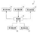
- FIG. 4 is a block diagram for explaining the electronic device 1.
- the electronic device 1 further includes a control unit 15.
- the control unit 15 controls an image displayed on the first display unit 11 based on the detection result of the first detection unit 14.
- the control unit 15 controls the image displayed on the second display unit 12 based on the detection result of the first detection unit 14 when the first detection unit 14 moves so as to overlap the second display unit 12. .
- Whether the first detection unit 14 overlaps with the first display unit 11 or the second display unit 12 is determined by, for example, a switch (not shown) arranged in each of the first display unit 11 and the second display unit 12. It is possible to make a determination based on whether or not the first detection unit 14 is in contact. For example, when the first detection unit 14 overlaps the first display unit 11 and a button (not shown) is displayed on the first display unit 11, the first detection unit 14 faces the button. When detecting contact with the position, the control unit 15 executes the function assigned to the button, assuming that the button has been operated. For example, when the first detection unit 14 overlaps the second display unit 12 and a button (not shown) is displayed on the second display unit 12, the first detection unit 14 faces the button. When detecting contact with the position, the control unit 15 executes the function assigned to the button, assuming that the button has been operated.
- the control part 15 performs the display control according to the contact detection by the 1st detection part 14.
- FIG. not necessary.
- the 1st detection part 14 is located between the 1st display part 11 side and the 2nd display part 12 side, as for the control part 15, the 1st detection part 14 is the 1st display part 11 and the 2nd display part. 12 is detected, and the control according to the contact detection by the first detection unit 14 is performed on the display on the first display unit 11 and the second display unit 12 detected as overlapping. You may go.
- the electronic device 1 performs detection for two screens by one first detection unit 14, the cost can be reduced and the power consumption can be reduced.
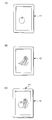
- FIG. 5 is a diagram for explaining an example of three-dimensional display.
- the control unit 15 causes the first display unit 11 and the second display unit 12 to display images related to each other in the closed state where the first display unit 11 and the second display unit 12 overlap each other.
- the first display unit 11 and the second display unit 12 are in the closed state, the first display unit 11 is disposed above the second display unit 12. That is, the user of the electronic device 1 can visually recognize the second display unit 12 via the first display unit 11.
- the control unit 15 causes the first display unit 11 to display an image (first image) that is on the near side with respect to the user, and an image (second image) that is on the far side of the first image with respect to the user. ) Is displayed on the second display unit 12.
- the image displayed on the first display unit 11 is displayed in front of the image displayed on the second display unit 12, and the electronic device 1 can display a pseudo three-dimensional screen. it can.
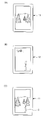
- control unit 15 displays an apple image (still image) as the first image on the first display unit 11 (see FIG. 5A). Moreover, the control part 15 displays the image (still image) of the banana as a 2nd image on the 2nd display part 12 (refer FIG.5 (B)). In the case of such an example, the user can visually recognize one stereoscopic image (see FIG. 5C) in which apples are arranged on the front side of the banana.
- FIG. 6 is a diagram for explaining an example of images displayed on the first display unit 11 and the second display unit 12.
- the control unit 15 causes the first display unit 11 and the second display unit 12 to display images related to each other based on one content in the closed state where the first display unit 11 and the second display unit 12 overlap each other.
- the control unit 15 displays a still image on the first display unit 11 and displays a moving image on the second display unit 12 based on one content.
- the still image displayed on the first display unit 11 is a partial image of one content
- the moving image displayed on the second display unit 12 is displayed on the first display unit 11 of the one content.
- the image of the image may be excluded.
- the control unit 15 causes the first display unit 11 to display the character together with the still image based on the content.
- the electronic device 1 can display the character as if it is raised during the reproduction of the moving image, and can improve the reality when reproducing the moving image.
- what is displayed on the first display unit 11 is not limited to a still image, and may be a moving image.
- the control unit 15 may display, for example, a moving character on the first display unit 11 without displaying a still image based on one content.
- control unit 15 displays a still image of a landscape on the first display unit 11 based on the content (see FIG. 6A). Further, the control unit 15 causes the display unit to display a moving image of the airplane in flight and the person looking up at the airplane (see FIG. 6B). The control unit 15 displays the person C on the first display unit 11 based on the content in order to emphasize the person as the character (see FIG. 6C). Thereby, the electronic device 1 can display the person C as if it is raised during the reproduction of the moving image, and can improve the reality during the reproduction of the moving image.
- the control unit 15 causes the first display unit 11 to display the parallax barrier 31 for performing the three-dimensional display when the first display unit 11 and the second display unit 12 transition to the closed state.
- the control unit 15 causes the second display unit 12 to display a three-dimensional image 32 for performing three-dimensional display.
- the 1st display part 11 and the 2nd display part 12 change to a closed state, the 1st display part 11 is arranged facing the surface where the display panel 12a is arranged in the 2nd display part 12. FIG. That is, the user can visually recognize the second display unit 12 via the first display unit 11.
- the parallax barrier 31 may be displayed on the second display unit 12 instead of being displayed on the first display unit 11, and the three-dimensional image 32 for performing three-dimensional display may be displayed on the first display unit 11. Good.
- the electronic device 1 can perform a three-dimensional display by a parallax barrier method when the first display unit 11 and the second display unit 12 transition to the closed state.
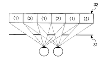
- FIG. 7 is a diagram for explaining the parallax barrier method.
- the parallax barrier 31 is a light blocking barrier provided with a plurality of slits that can transmit the three-dimensional image 32 displayed on the second display unit 12.
- the three-dimensional image 32 is an image in which the left-eye image (1) and the right-eye image (2) are alternately arranged.
- the electronic device 1. May display characters or images in three dimensions.
- displaying characters or images in three dimensions means, for example, displaying the parallax barrier 31 on the first display unit 11 and displaying three-dimensional characters or images on the second display unit 12.
- Good That is, among the contents (for example, characters or images) displayed on the second display section 12 when the first display section 11 and the second display section 12 are in the open state, the same contents (for example, characters or When the first display unit 11 and the second display unit 12 transition to the closed state, the three-dimensional character or image of (image) may be displayed on the second display unit.
- displaying the animal in three dimensions may be, for example, displaying the parallax barrier 31 on the first display unit 11 and displaying a three-dimensional animal image on the second display unit 12. That is, among the contents (for example, the names and explanations of animals) displayed on the second display section 12 when the first display section 11 and the second display section 12 are in the open state, they are particularly characteristic among the contents.
- a three-dimensional image of an image may be displayed on the second display unit when the first display unit 11 and the second display unit 12 transition to the closed state.
- displaying the graphic in three dimensions may be, for example, displaying the parallax barrier 31 on the first display unit 11 and displaying an image of a three-dimensional graphic on the second display unit 12. That is, a three-dimensional image (for example, a graphic) related to content (for example, mathematical problems and explanations) displayed on the second display unit 12 when the first display unit 11 and the second display unit 12 are open.
- an image for use may be displayed on the second display unit.
- the electronic device 1 can perform a three-dimensional display.
- the electronic device 1 further includes a third detection unit 16.
- the third detection unit 16 detects that the first display unit 11 and the second display unit 12 are in a closed state. In this case, when the third detection unit 16 detects that the first display unit 11 and the second display unit 12 are in the closed state, the control unit 15 applies the parallax barrier 31 to the first display unit 11. At the same time, the 3D image 32 is displayed on the second display unit 12.
- the 3rd detection part 16 may detect whether the 1st display part 11 and the 2nd display part 12 have mutually overlapped.
- the third detection unit 16 detects that the first display unit 11 and the second display unit 12 are closed when at least a part of the first display unit 11 and the second display unit 12 overlap each other in the thickness direction. When the second display unit 12 and the second display unit 12 do not overlap with each other in the thickness direction, the open state may be detected.
- the third detection unit 16 includes, for example, a Hall element (not shown) and a magnet (not shown).
- the hall element is disposed on one of the first display unit 11 and the second display unit 12.
- the magnet is disposed on the other of the first display unit 11 and the second display unit 12.
- a magnet is distribute
- the third detection unit 16 detects whether or not the first display unit 11 and the second display unit 12 are closed based on the magnitude of the magnetic force detected by the Hall element.
- the electronic device 1 can automatically perform a three-dimensional display. it can.
- the electronic device 1 can perform two-dimensional display when the third detection unit 16 does not detect that the first display unit 11 and the second display unit 12 are in the closed state.
- the 3rd detection part 16 is not limited to the structure provided with a Hall element and a magnet, ON / OFF is switched according to the open state or closed state of the 1st display part 11 and the 2nd display part 12. It may be a switch.
- the electronic device 1 further includes a second detection unit 17.
- the second detection unit 17 detects the orientations of the first display unit 11 and the second display unit 12.
- the control unit 15 determines whether the parallax barrier 31 displayed on the first display unit 11 and the three-dimensional image 32 displayed on the second display unit 12 are based on the detection result of the second detection unit 17. Change the orientation.
- the second detection unit 17 detects the attitude of the electronic device 1 by detecting the acceleration, movement, inclination, or the like of the electronic device 1. That is, the second detection unit 17 detects whether the electronic device 1 is arranged in the vertical direction or in the horizontal direction. More specifically, for example, when the first display unit 11 and the second display unit 12 are rectangular, the second detection unit 17 includes the first display unit 11 (display panel 11a) and the second display unit 12.
- the (display panel 12a) faces the user, and the longitudinal direction of the first display unit 11 and the second display unit 12 is, for example, along the vertical direction (or substantially vertical direction) with respect to the ground, or the first display unit It is detected whether the longitudinal direction of 11 and the 2nd display part 12 is along a horizontal direction (or substantially horizontal direction) with respect to the ground, for example.
- the second detection unit 17 includes, for example, a gravity sensor, a gyro sensor, an acceleration sensor, an angular velocity sensor, or the like.
- the control unit 15 includes the first display unit 11 and the second display unit 11.
- a three-dimensional image and a parallax barrier based on the longitudinal direction of the display panels 11a and 12a of the display unit 12 are displayed on the display units 11 and 12, respectively.
- the control unit 15 includes the first display unit 11 and the second display unit 11.
- a three-dimensional image and a parallax barrier based on the short direction of the display panels 11 a and 12 a of the display unit 12 are displayed on the display units 11 and 12. Thereby, even when the postures of the first display unit 11 and the second display unit 12 change, the electronic device 1 can display the three-dimensional image and the parallax barrier corresponding to the postures on the display units 11 and 12. . *
- the first display unit 11 is a transparent display.
- the second display unit 12 is electronic paper.
- the control unit 15 performs control so that a moving image is displayed on the first display unit 11.
- the control unit 15 controls the second display unit 12 to display a still image or characters.
- the 1st display part 11 When the 1st display part 11 is a transparent display, the 1st display part 11 is suitable for reproduction
- the second display unit 12 When the second display unit 12 is electronic paper, the second display unit 12 is suitable for displaying characters or still images. For this reason, when the first display unit 11 and the second display unit 12 are in the closed state, the electronic device 1 displays a moving image on the first display unit 11 and displays characters or still images on the second display unit 12. If displayed, moving images, characters, and still images can be displayed with high image quality. In addition, the video and text can be displayed superimposed, and the video display space is not divided into the text display space, so you can enjoy the video and check the text related to it as well. I can know.
- FIG. 8 is a diagram for explaining a third example of the electronic apparatus 1.
- the electronic device 1 preferably further includes a first detection unit 14 and a second connection unit 18.
- the first detection unit 14 detects contact of, for example, a finger or a pointer. What is the side of the second display unit 12 on the first display unit 11 side so that the second connection unit 18 can be arranged so that the second display unit 12 and the first detection unit 14 overlap each other. On the other different side, the second display unit 12 and the first detection unit 14 are connected.
- the 2nd connection part 18 is a hinge part.
- the first connecting portion 13 that connects the first display portion 11 and the second display portion 12 is a hinge portion.
- the first display unit 11 is folded in the ⁇ X direction with respect to the second display unit 12.
- the first detection unit 14 is folded in the + X direction with respect to the second display unit 12. That is, in the case shown in FIG. 9A, the first detection unit 14, the second display unit 12, and the first display unit 11 are sequentially stacked in this order from the direction A that is visually recognized by the user.
- the first display unit 11 is folded in the + X direction with respect to the second display unit 12.
- the first detection unit 14 is folded in the + X direction with respect to the first display unit 11. That is, in the case shown in FIG. 9B, the first detection unit 14, the first display unit 11, and the second display unit 12 are sequentially stacked in this order from the direction A that the user visually recognizes.
- the first display unit 11 is a transparent display.
- the second display unit 12 is electronic paper.
- the control unit 15 performs control so that a moving image is displayed on the first display unit 11.
- the control unit 15 controls the second display unit 12 to display a still image or characters.
- the control unit 15 when an electronic book is displayed on the electronic device 1, the control unit 15 causes the second display unit 12 to display characters. In this case, the control unit 15 does not display an image on the first display unit 11.
- the control unit 15 when moving to the next page, the control unit 15 causes the first display unit 11 to display a moving image or an image when the page is turned. At this time, the control unit 15 rewrites the character displayed on the second display unit 12 with the character on the next page.
- the first detection unit 14 can be a display unit. In this case, the electronic device 1 can perform three-layer image display, and enables further pseudo-stereoscopic viewing compared to two-layer pseudo-stereoscopic viewing.
Landscapes
- Engineering & Computer Science (AREA)
- Theoretical Computer Science (AREA)
- Computer Hardware Design (AREA)
- Physics & Mathematics (AREA)
- General Engineering & Computer Science (AREA)
- General Physics & Mathematics (AREA)
- Human Computer Interaction (AREA)
- Signal Processing (AREA)
- Mathematical Physics (AREA)
- Controls And Circuits For Display Device (AREA)
- User Interface Of Digital Computer (AREA)
- Telephone Set Structure (AREA)
- Telephone Function (AREA)
- Digital Computer Display Output (AREA)
- Devices For Indicating Variable Information By Combining Individual Elements (AREA)
Abstract
ユーザの利便性を向上させた電子機器を提供する。電子機器は、第1表示部と、第2表示部と、第1連結部と、を備える。第1表示部は、光の透過性を有する。第1連結部は、第1表示部及び第2表示部が開状態と閉状態とに相互に遷移するように、第1表示部と第2表示部とを連結する。第1表示部と第2表示部とが重なる閉状態において第1表示部を通して第2表示部を視認することが可能である。
Description
本発明は、複数の表示部を備える電子機器に関する。
電子機器の一例には、携帯電話機が挙げられる。携帯電話機には、2つの筐体をヒンジ部で接続して、折り畳み可能としたタイプがある。折り畳み型の携帯電話機には、2つの筐体が閉状態になる場合でも容易に操作できるようにするために、透明ディスプレイを備えるタイプがある(特許文献1参照)。
上述したように、電子機器には、透明ディスプレイを備えるタイプがある。近年は、透明ディスプレイが光透過性を有するという利点を生かして、さらにユーザにとって利便性の高い電子機器の登場が望まれている。
本発明は、ユーザの利便性を向上させた電子機器を提供することを目的とする。
本発明の電子機器の一態様は、第1表示部と、第2表示部と、第1連結部と、を備える。前記第1表示部は、光の透過性を有する。前記第1連結部は、第1表示部及び第2表示部が開状態と閉状態とに相互に遷移するように、前記第1表示部と前記第2表示部とを連結する。開状態とは、前記第1表示部と前記第2表示部とが重ならない状態である。閉状態とは、前記第1表示部と前記第2表示部とが重なる状態である。前記第1表示部と前記第2表示部とが重なる閉状態において前記第1表示部を通して前記第2表示部を視認することが可能である。
上記の電子機器は、第1検出部をさらに備えてもよい。前記第1検出部は、前記第1表示部と前記第2表示部とが開状態に遷移した場合に、前記第1表示部と前記第2表示部との少なくとも一方に重なるように相互に移動することが可能である。前記第1検出部は、接触を検出する。
上記の電子機器は、以下のような制御部をさらに備えてもよい。前記制御部は、前記第1検出部が前記第1表示部に重なるように移動した場合には、前記第1検出部の検出結果に基づいて前記第1表示部に表示される画像を制御する。前記制御部は、前記第1検出部が前記第2表示部に重なるように移動した場合には、前記第1検出部の検出結果に基づいて前記第2表示部に表示される画像を制御する。
上記の電子機器は、以下のような制御部をさらに備えてもよい。前記制御部は、前記第1表示部と前記第2表示部とが重なる閉状態において、互いに関連する画像を前記第1表示部と前記第2表示部にそれぞれ表示させる。
上記の電子機器は、以下のような制御部をさらに備えてもよい。前記制御部は、前記第1表示部と前記第2表示部とが重なる閉状態において、一のコンテンツに基づく互いに関連する画像を前記第1表示部と前記第2表示部にそれぞれ表示させる。
前記第1表示部と前記第2表示部とが開状態に遷移した場合において、前記第1検出部が前記第1表示部に重なるように移動すると、前記第1検出部は、前記第1表示部の一方の面側に配されてもよい。前記第1検出部が前記第2表示部に重なるように移動すると、前記第1検出部は、前記第1表示部の前記一方の面に近い前記第2表示部の面側に配されてもよい。
上記の電子機器は、以下のような制御部をさらに備えてもよい。前記制御部は、前記第1表示部と前記第2表示部とが閉状態に遷移した場合に、3次元表示を行うための視差バリアを前記第1表示部に表示させる。前記制御部は、前記第1表示部と前記第2表示部とが閉状態に遷移した場合に、3次元表示を行うための3次元用画像を前記第2表示部に表示させる。
上記の電子機器は、第2検出部をさらに備えてもよい。前記第2検出部は、前記第1表示部及び前記第2表示部の向きを検出する。前記制御部は、前記第2検出部の検出結果に基づいて、前記第1表示部に表示される視差バリアと、前記第2表示部に表示される3次元用画像との向きを変更する。
上記の電子機器は、以下のような制御部をさらに備えてもよい。前記制御部は、前記第1表示部に動画を表示させるよう制御する。前記制御部は、前記第2表示部に静止画又は文字を表示させるよう制御する。
上記の電子機器は、第1検出部と、第2連結部と、をさらに備えてもよい。前記第1検出部は、接触を検出する。前記第2連結部は、前記第2表示部と前記第1検出部とが重なるように配されることが可能になるように、前記第2表示部における前記第1表示部と連結されている一方の辺とは異なる他方の辺側において、前記第2表示部と前記第1検出部とを連結する。
上記の電子機器において、前記第1表示部は、透明ディスプレイであってもよい。前記第2表示部は、電子ペーパーであってもよい。
上記の電子機器において、前記第1表示部と前記第2表示部とが互いに重なる状態において、前記第1表示部に一のコンテンツにおける一部の画像を表示させる制御部をさらに備えてもよい。
本発明の電子機器の別の態様は、透過性を有する第1表示部と第2表示部とを備える。前記第1表示部と前記第2表示部とが互いに重なる場合に、3次元表示を行うための視差バリアを前記第1表示部に表示させると共に、3次元表示を行うための3次元用画像を前記第2表示部に表示させる。
本発明の電子機器の別の態様は、光の透過性を有する第1表示部と、第2表示部と、前記第1表示部と前記第2表示部とが重ならない開状態と、前記第1表示部と前記第2表示部とが重なる閉状態とに相互に遷移するように、前記第1表示部と前記第2表示部とを連結する第1連結部と、を備える。前記第1表示部と前記第2表示部とが重なる閉状態において、前記第2表示部から発光された光が前記第1表示部を透過する。
本発明によれば、ユーザの利便性を向上させた電子機器を提供することができる。
以下、本発明の一実施形態について説明する。図1は、電子機器1の第1の例について説明するための図である。
図1に示す電子機器1は、第1表示部11と、第2表示部12と、第1連結部13と、を備える。第1表示部11は、光の透過性を有する。すなわち、第1表示部11は、透過型の表示部である。このため、第1表示部11は、表面側から裏面側の景色を透かして視認することが可能であると共に、裏面側から表面側の景色を透かして視認することが可能である。第1表示部11は、ディスプレイパネル11a、及びディスプレイパネル11aを保持する枠体11b(筐体)等を備える。第1表示部11のディスプレイパネル11aは、例えば、液晶パネルである。また、第1表示部11は、非発光型でなく、自発光型であってもよく、自発光型ディスプレイの例として、有機ELディスプレイであってもよい。
また、第1表示部11は、自発光型のディスプレイパネル11aを設けなくてもよい。また、第1表示部11は、非発光型のディスプレイパネル11aを設けた場合、ディスプレイパネル11aを照らすバックライトを設けなくてもよい。その場合、重畳された第2表示部12に設けられたバックライトの光、第2表示部12自身が発光する光若しくは周囲の光により、第1表示部11のディスプレイパネル11aが照らされ、第1表示部11の表示をユーザが視認することが可能となる。また、第1表示部11のディスプレイパネル11aは、透明液晶、透過ディスプレイ、透過液晶のいずれかであってもよい。
また、第1表示部11は、自発光型のディスプレイパネル11aを設けなくてもよい。また、第1表示部11は、非発光型のディスプレイパネル11aを設けた場合、ディスプレイパネル11aを照らすバックライトを設けなくてもよい。その場合、重畳された第2表示部12に設けられたバックライトの光、第2表示部12自身が発光する光若しくは周囲の光により、第1表示部11のディスプレイパネル11aが照らされ、第1表示部11の表示をユーザが視認することが可能となる。また、第1表示部11のディスプレイパネル11aは、透明液晶、透過ディスプレイ、透過液晶のいずれかであってもよい。
第2表示部12は、光の透過性を有しない。第2表示部12は、ディスプレイパネル12a、及びディスプレイパネル12aが配される筐体12b等を備える。第2表示部12のディスプレイパネル12aは、例えば、液晶パネルである。なお、第2表示部12は、光の透過性を有しないものに限られず、光の透過性を有するものであってもよい。また、第2表示部12のディスプレイパネル12aは、有機ELディスプレイであってもよい。また、第2表示部12のディスプレイパネル12aは、透明液晶、透過ディスプレイ、透過液晶のいずれかであってもよい。
第1連結部13は、第1表示部11及び第2表示部12が開状態(図1(A)参照)と閉状態(図1(B)参照)とに相互に遷移するように、第1表示部11と第2表示部12とを連結する。開状態は、第1表示部11と第2表示部12とが重ならない状態である。開状態においては、第1表示部11と第2表示部12とで略平面を形成させることもできる。閉状態は、第1表示部11と第2表示部12とが重なる状態である。図1に示される第1連結部13は、ヒンジ部である。
第1表示部11と第2表示部12とが重なる閉状態では、ユーザは、第1表示部11を通して第2表示部12を視認することが可能である。これによって、閉状態においては、第1表示部11の画面と第2表示部12の画面とを重ねて視認することができる。例えば、第1表示部11には、人の写真の画面を表示し、第2表示部には風景画面を表示することにより、あたかも第1表示部11に表示されている写真中の人が第2表示部12に表示されている風景の中にいるように表示することができる。また、例えば、第1表示部11に受信したメールの文章を表示し、第2表示部12に受信したメールに添付されている画像を表示することにより、メールの文章を読みながら、同時に画面を確認することができ、あたかもメールの文章が画像に関連付けられていることをユーザが認識できると共にメールの文章及び画像をそれぞれ確認する手間も省ける。このとき、第1表示部11に表示されるメールの文章と、第2表示部12に表示されるメールに添付されている画像とは、ユーザーから見て互いに重なっていてもよい。第1表示部11と第2表示部12とが重なる閉状態では、各ディスプレイパネル11a,12aは、重なるように配される。電子機器1は、第1表示部11と第2表示部12とが開状態となる場合には、2つの表示部11,12によって大画面の表示部を提供することができる。
電子機器1は、第1表示部11と第2表示部12とが閉状態となる場合には、2つの表示部11,12を重ねて1画面の表示部を提供することができる。例えば、電子機器1は、第1表示部11に動画を表示させ、第2表示部12に文字又は静止画を表示させるように、表示部11,12の役割を分担させることが可能である。この場合には、電子機器1は、文字又は静止画に重ねて動画を表示することが可能であるため、種々の表示を行うことができる。よって、電子機器1は、大画面の表示部及び1画面の表示部を提供できるので、ユーザの利便性を向上させることができる。
図2は、電子機器1の第2の例について説明するための図である。図2に示す電子機器1は、第1表示部11と、第2表示部12と、第1連結部13と、を備える。第1表示部11及び第2表示部12は、図1に示す電子機器1に用いられる第1表示部11及び第2表示部12と同様の構成である。
第1連結部13は、第1表示部11及び第2表示部12が開状態(図2(A)参照)と閉状態(図2(B)参照)とに相互に遷移するように、第1表示部11と第2表示部12とを連結する。開状態は、第1表示部11と第2表示部12とが重ならない状態である。開状態においては、第1表示部11と第2表示部12とで略平面を形成させることもできる。閉状態は、第1表示部11と第2表示部12とが重なる状態である。図2に示される第1連結部13は、リンク部材である。第1連結部13は、例えば、第1表示部11の側面における中央部付近と、第2表示部12の側面における端部付近とに係合する。このような電子機器1では、第1表示部11と第2表示部12とが重なる閉状態では、ユーザは、第1表示部11を通して第2表示部12を視認することが可能である。また、第1表示部11と第2表示部12とが重なる閉状態において、第2表示部12から発光された光が第1表示部11を透過する。
これにより、電子機器1は、大画面の表示部及び1画面の表示部を提供できるので、ユーザの利便性を向上させることができる。
電子機器1は、第1検出部14をさらに備える。第1検出部14は、接触を検出する。具体的には、第1検出部14は、タッチパネルである。
第1検出部14は、第1表示部11と第2表示部12とが開状態に遷移した場合に、第1表示部11に重なるよう又は第2表示部12に重なるように相互に移動することが可能である。第1検出部14は、不図示のスライド機構により、スライド移動が可能になっている。
図1に示すような電子機器1では、第1表示部11と第2表示部12とが平面を構成するような開状態となった場合に、第1検出部14は、第1表示部11及び第2表示部12の上面を移動することが可能になる。
図2に示す電子機器1では、第1検出部14は、以下に説明するように移動することが可能である。図3は、第1検出部14の移動について説明するための図である。第1表示部11と第2表示部12とが開状態に遷移した場合において、第1検出部14が第1表示部11に重なるように移動すると、第1検出部14は、第1表示部11の一方の面側に配される(図3(A)参照)。一方の面とは、図3において下面のことである。よって、図3(A)に示す場合では、第1検出部14は、第1表示部11の下面側に配される。第1表示部11は透過型の表示部であるため、第1検出部14が第1表示部11の下面に配される場合でも、ユーザは、位置を確認しながら第1検出部14をタッチすることができる。
第1表示部11と第2表示部12とが開状態に遷移した場合において、第1検出部14が第2表示部12に重なるように移動すると、第1検出部14は、第2表示部12における第1表示部11の一方の面に近い面側に配される(図3(B)参照)。第2表示部12における第1表示部11の一方の面に近い面とは、図3において上面のことである。よって、図3(B)に示す場合では、第1検出部14は、第2表示部12の上面側に配される。なお、第1表示部11と第2表示部12とが開状態に遷移した場合であって、第1表示部11の上面と第2表示部12の上面とが互いに同一平面であるとき、前述の第2表示部12における第1表示部の一方の面に近い面は、図3における下面となる。
ここで、図2に示す電子機器1に配される第1検出部14は、上面への接触と、下面への接触とを検出することができる。このような第1検出部14は、1枚のタッチパネルで上面への接触と下面への接触を検出することができる。又は、第1検出部14は、上面への接触を検出するタッチパネルと、下面への接触を検出するタッチパネルとを積層させることにより、上面への接触と下面への接触を検出することができる。
なお、電子機器1は、第1検出部14を第1表示部11及び第2表示部12に亘って移動させるスライダ部(図示せず)を第1表示部11(枠体11b)及び第2表示部12(筐体12b)に設けた構成であってもよい。スライダ部は、第1表示部11(枠体11b)及び第2表示部12(筐体12b)の表裏のいずれにも設けてもよい。これにより、第1検出部14は、例えば、第1表示部11の下面側(裏側)から第2表示部12の上面側(表側)へ移動が可能である。又は、第1検出部14は、例えば、第1表示部11の上面側(表側)から第2表示部12の上面側(表側)へ移動が可能である。又は、第1検出部14は、例えば、第1表示部11の下面側(裏側)から第2表示部12の下面側(裏側)へ移動が可能である。
また、第1検出部14は、可撓性を有するタッチパネルであってもよい。また、電子機器1が折り畳み型の携帯電話機の場合、第1検出部14(タッチパネル)は撓むと共に、第1筐体(上側筐体)と第2筐体(下側筐体)とを移動してもよい。
また、第1表示部11と第2表示部12とが開状態となることによって、第1表示部11と第2表示部12とが略平面を形成することが可能な場合には、第1検出部14は、第1表示部11及び第2表示部12それぞれの下面側又は上面側を移動することも可能である。
図4は、電子機器1について説明するためのブロック図である。電子機器1は、制御部15をさらに備える。制御部15は、第1検出部14が第1表示部11に重なるように移動した場合には、第1検出部14の検出結果に基づいて第1表示部11に表示される画像を制御する。制御部15は、第1検出部14が第2表示部12に重なるように移動した場合には、第1検出部14の検出結果に基づいて第2表示部12に表示される画像を制御する。
第1検出部14が第1表示部11及び第2表示部12のいずれに重なったかは、例えば、第1表示部11及び第2表示部12のそれぞれに配されるスイッチ(図示せず)に第1検出部14が接触したか否かに基づいて判断することが可能である。例えば、第1検出部14が第1表示部11に重なり、且つ、第1表示部11にボタン(図示せず)が表示されているとした場合において、第1検出部14によってボタンに対向する位置への接触を検出すると、制御部15は、ボタンが操作されたとして、そのボタンに割り当てられた機能を実行する。例えば、第1検出部14が第2表示部12に重なり、且つ、第2表示部12にボタン(図示せず)が表示されているとした場合において、第1検出部14によってボタンに対向する位置への接触を検出すると、制御部15は、ボタンが操作されたとして、そのボタンに割り当てられた機能を実行する。
なお、第1検出部14が第1表示部11側と第2表示部12側との間に位置する場合、制御部15は、第1検出部14による接触検出に応じた表示制御を実行しなくともよい。又は、第1検出部14が第1表示部11側と第2表示部12側との間に位置する場合、制御部15は、第1検出部14が第1表示部11と第2表示部12とのどこまで重なっているかを検出し、当該重なっていると検出された第1表示部11と第2表示部12との表示に対して、第1検出部14による接触検出に応じた制御を行ってもよい。
これにより、電子機器1は、1つの第1検出部14で2画面分の検出を行うため、コストダウンが図れると共に、低消費電力化を果たすことができる。
図5は、3次元表示の一例について説明するための図である。制御部15は、第1表示部11と第2表示部12とが重なる閉状態において、互いに関連する画像を第1表示部11と第2表示部12とにそれぞれ表示させる。第1表示部11と第2表示部12とが閉状態となる場合、第1表示部11は、第2表示部12の上方に配される。すなわち、電子機器1のユーザは、第1表示部11を介して第2表示部12を視認可能になる。この場合、制御部15は、ユーザに対して手前側に来る画像(第1画像)を第1表示部11に表示させ、ユーザに対して第1画像よりも奥側に来る画像(第2画像)を第2表示部12に表示させる。これにより、第1表示部11に表示された画像が第2表示部12に表示された画像よりも前側に表示されることになり、電子機器1は、擬似的な立体画面を表示することができる。
一例として、制御部15は、第1画像としてのりんごの画像(静止画)を第1表示部11に表示させる(図5(A)参照)。また、制御部15は、第2画像としてのバナナの画像(静止画)を第2表示部12に表示させる(図5(B)参照)。このような例の場合では、ユーザは、バナナの手前側にりんごが配置された一枚の立体的な画像(図5(C)参照)を視認することができる。
図6は、第1表示部11と第2表示部12に表示される画像の一例について説明するための図である。制御部15は、第1表示部11と第2表示部12とが重なる閉状態において、一のコンテンツに基づく互いに関連する画像を第1表示部11と第2表示部12とにそれぞれ表示させる。例えば、制御部15は、一のコンテンツに基づいて、静止画を第1表示部11に表示させ、動画を第2表示部12に表示させる。ここで、第1表示部11に表示させる静止画は、一のコンテンツにおける一部の画像であり、第2表示部12に表示させる動画は、一のコンテンツにおける第1表示部11に表示させる一部の画像を除いたものであってもよい。第2表示部12に表示される動画の中に浮き出させたいキャラクタが存在する場合、制御部15は、コンテンツに基づいて、静止画と共にそのキャラクタを第1表示部11に表示させる。これにより、電子機器1は、動画再生中にあたかもキャラクタが浮き出ているように表示することが可能になり、動画再生時のリアリティを向上させることができる。また、第1表示部11に表示されるものは、静止画に限定されず、動画であってもよい。なお、制御部15は、一のコンテンツに基づいて、静止画を表示させずに、例えば動くキャラクタを第1表示部11に表示させてもよい。
一例として、制御部15は、コンテンツに基づいて、風景の静止画を第1表示部11に表示させる(図6(A)参照)。また、制御部15は、飛行中の飛行機と、その飛行機を見上げている人との動画を表示部に表示させる(図6(B)参照)。制御部15は、キャラクタとしての人を強調するために、コンテンツに基づいて、人Cを第1表示部11に表示させる(図6(C)参照)。これにより、電子機器1は、動画再生中に人Cが浮き出ているように表示することが可能になり、動画再生時のリアリティを向上させることができる。
制御部15は、第1表示部11と第2表示部12とが閉状態に遷移した場合に、3次元表示を行うための視差バリア31を第1表示部11に表示させる。この場合、制御部15は、3次元表示を行うための3次元用画像32を第2表示部12に表示させる。第1表示部11と第2表示部12とが閉状態に遷移した場合、第2表示部12においてディスプレイパネル12aが配される面に対向して第1表示部11が配される。すなわち、ユーザは、第1表示部11を介して第2表示部12を視認することが可能である。なお、視差バリア31を、第1表示部11に表示させる代わりに第2表示部12に表示させると共に、3次元表示を行うための3次元用画像32を第1表示部11に表示させてもよい。
電子機器1は、第1表示部11と第2表示部12とが閉状態に遷移した場合に、視差バリア方式で3次元表示を行うことが可能である。図7は、視差バリア方式について説明するための図である。視差バリア31は、第2表示部12に表示された3次元用画像32を透過することが可能なスリットが複数も設けられた遮光バリアである。3次元用画像32は、左目用の画像(1)と右目用の画像(2)とが交互に並べられた画像である。
ここで、例えば、第2表示部12に学習教材の文字又は画像を2次元で表示している場合に、第1表示部11と第2表示部12とが閉状態に遷移すると、電子機器1は、文字又は画像を3次元で表示させてもよい。ここで、文字又は画像を3次元で表示させるとは、例えば、第1表示部11に視差バリア31を表示させると共に、第2表示部12に3次元用の文字又は画像を表示させることとしてもよい。つまり、第1表示部11と第2表示部12とが開状態において第2表示部12に表示されているコンテンツ(例えば、文字又は画像)のうち、当該コンテンツと同一のコンテンツ(例えば、文字又は画像)の3次元用の文字又は画像を、第1表示部11と第2表示部12とが閉状態に遷移すると、第2表示部に表示させることとしてもよい。より具体的な例としては、第2表示部12に動物の名前と解説とを2次元で表示している場合に、第1表示部11と第2表示部12とが閉状態に遷移すると、その動物を3次元で表示させる。ここで、動物を3次元で表示させるとは、例えば、第1表示部11に視差バリア31を表示させると共に、第2表示部12に3次元用の動物の画像を表示させることとしてもよい。つまり、第1表示部11と第2表示部12とが開状態において第2表示部12に表示されているコンテンツ(例えば、動物の名前と解説)のうち、当該コンテンツの中で特に特徴的な画像(例えば、動物)の3次元用の画像を、第1表示部11と第2表示部12とが閉状態に遷移すると、第2表示部に表示させることとしてもよい。より具体的な別の例としては、第2表示部12に数学の問題と解説とを2次元で表示している場合に、第1表示部11と第2表示部12とが閉状態に遷移すると、数学の問題と解説に関連する図形を三次元で表示させる。ここで、図形を3次元で表示させるとは、例えば、第1表示部11に視差バリア31を表示させると共に、第2表示部12に3次元用の図形の画像を表示させることとしてもよい。つまり、第1表示部11と第2表示部12とが開状態において第2表示部12に表示されているコンテンツ(例えば、数学の問題と解説)に関連する画像(例えば、図形)の3次元用の画像を、第1表示部11と第2表示部12とが閉状態に遷移すると、第2表示部に表示させることとしてもよい。これにより、電子機器1は、3次元表示を行うことができる。
電子機器1は、第3検出部16をさらに備える。第3検出部16は、第1表示部11と第2表示部12とが閉状態になったことを検出する。この場合、制御部15は、第3検出部16によって第1表示部11と第2表示部12とが閉状態になったことが検出された場合に、第1表示部11に視差バリア31を表示させると共に、第2表示部12に3次元用画像32を表示させる。ここで、第3検出部16は、第1表示部11と第2表示部12とが互いに重なっているか否かを検出するものであってもよい。例えば、第3検出部16は、第1表示部11と第2表示部12との少なくとも一部がその厚さ方向に互いに重なっている場合には、閉状態と検出し、第1表示部11と第2表示部12とがその厚さ方向に互いに重なっていない場合には、開状態と検出するものであってもよい。
第3検出部16は、例えば、ホール素子(図示せず)と、磁石(図示せず)と、を備える。ホール素子は、第1表示部11及び第2表示部12のうち一方に配される。磁石は、第1表示部11及び第2表示部12のうち他方に配される。第1表示部11及び第2表示部12が閉状態に遷移した場合、磁石は、ホール素子に対向する位置に配される。第3検出部16は、ホール素子によって検出される磁力の大きさに基づいて、第1表示部11と第2表示部12とが閉状態になったか否かを検出する。これにより、電子機器1は、第3検出部16によって第1表示部11と第2表示部12とが閉状態になったことを検出した場合には、自動的に3次元表示を行うことができる。また、電子機器1は、第3検出部16によって第1表示部11と第2表示部12とが閉状態になったことを検出しない場合には、2次元表示を行うことができる。
なお、第3検出部16は、ホール素子と磁石とを備える構成に限定されることはなく、第1表示部11と第2表示部12との開状態又は閉状態に応じてオンオフが切り替えられるスイッチであってもよい。
電子機器1は、第2検出部17をさらに備える。第2検出部17は、第1表示部11及び第2表示部12の向きを検出する。この場合、制御部15は、第2検出部17の検出結果に基づいて、第1表示部11に表示される視差バリア31と、第2表示部12に表示される3次元用画像32との向きを変更する。
第2検出部17は、電子機器1の加速度、動き又は傾き等を検出することにより、電子機器1の姿勢を検出する。すなわち、第2検出部17は、電子機器1は縦方向に配置されているのか、又は、横方向に配置されているのかを検出する。より具体的には、例えば、第1表示部11と第2表示部12とが矩形の場合には、第2検出部17は、第1表示部11(ディスプレイパネル11a)及び第2表示部12(ディスプレイパネル12a)がユーザに向くと共に、第1表示部11と第2表示部12との長手方向が例えば地面に対して鉛直方向(又は略鉛直方向)に沿っているのか又は第1表示部11と第2表示部12との長手方向が例えば地面に対して水平方向(又は略水平方向)に沿っているのかを検出する。第2検出部17は、例えば、重力センサ、ジャイロセンサ、加速度センサ又は角速度センサ等を備える。
例えば、第1表示部11及び第2表示部12のディスプレイパネル11a,12aの長手方向が例えば地面に対して垂直になる状態の場合には、制御部15は、第1表示部11及び第2表示部12のディスプレイパネル11a,12aの長手方向を基準とする3次元画像及び視差バリアをそれぞれ表示部11,12に表示させる。また、第1表示部11及び第2表示部12のディスプレイパネル11a,12aの長手方向が例えば地面に対して水平になる状態の場合には、制御部15は、第1表示部11及び第2表示部12のディスプレイパネル11a,12aの短手方向を基準とする3次元画像及び視差バリアを表示部11,12に表示させる。これにより、電子機器1は、第1表示部11と第2表示部12の姿勢が変化した場合でも、その姿勢に応じた3次元画像及び視差バリアを表示部11,12に表示することができる。
第1表示部11は、透明ディスプレイである。第2表示部12は、電子ペーパーである。この場合、制御部15は、第1表示部11に動画を表示させるよう制御する。制御部15は、第2表示部12に静止画又は文字を表示させるよう制御する。
第1表示部11が透明ディスプレイである場合、第1表示部11は、動画の再生(表示)に適する。第2表示部12が電子ペーパーである場合、第2表示部12は、文字又は静止画の表示に適する。このため、電子機器1は、第1表示部11と第2表示部12とが閉状態となる場合に、第1表示部11に動画を表示させ、第2表示部12に文字又は静止画を表示させれば、動画、文字、静止画を高画質で表示させることが可能になる。また、動画と文字を重ね合わせて表示させることができ、かつ動画の表示スペースを文字の表示スペースに割くことがなくなるので、動画を楽しむと同時にそれに関する文字も確認でき、動画の内容の詳細を知ることができる。
図8は、電子機器1の第3の例について説明するための図である。電子機器1は、第1検出部14と、第2連結部18と、をさらに備えることが好ましい。第1検出部14は、例えば指やポインタ等の接触を検出する。第2連結部18は、第2表示部12と第1検出部14とが重なるように配されることが可能になるように、第2表示部12の第1表示部11側の辺とは異なる他方の辺側において、第2表示部12と第1検出部14とを連結する。第2連結部18は、ヒンジ部である。また、第3の例の電子機器1では、第1表示部11と第2表示部12とを連結する第1連結部13は、ヒンジ部である。
図9は、電子機器1を側面(上面)から見た場合における、第1表示部11、第2表示部12及び第1検出部14の折り畳み形態について説明するための図である。電子機器1は、図9(A)及び図9(B)それぞれに示すように折り畳まれる。図9(A)及び図9(B)に示す場合では、ユーザは、図面の下側から電子機器1を視認するようになる。
図9(A)に示す場合では、第1表示部11は、第2表示部12に対して-X方向に折り畳まれる。また、図9(A)に示す場合では、第1検出部14は、第2表示部12に対して+X方向に折り畳まれる。すなわち、図9(A)に示す場合では、第1検出部14、第2表示部12及び第1表示部11は、この順番でユーザが視認する方向Aから順に積層される。
一方、図9(B)に示す場合では、第1表示部11は、第2表示部12に対して+X方向に折り畳まれる。また、図9(B)に示す場合では、第1検出部14は、第1表示部11に対して+X方向に折り畳まれる。すなわち、図9(B)に示す場合では、第1検出部14、第1表示部11及び第2表示部12は、この順番でユーザが視認する方向Aから順に積層される。
第1表示部11は、透明ディスプレイである。第2表示部12は、電子ペーパーである。制御部15は、第1表示部11に動画を表示させるよう制御する。制御部15は、第2表示部12に静止画又は文字を表示させるよう制御する。
例えば、電子機器1で電子書籍を表示している場合には、制御部15は、第2表示部12に文字を表示させる。この場合、制御部15は、第1表示部11には、画像を表示させない。電子機器1で電子書籍を表示している場合に、次ページに移行するときには、制御部15は、ページがめくられるときの動画若しくは画像を第1表示部11に表示させる。このとき、制御部15は、第2表示部12に表示される文字を次ページの文字に書き換える。これにより、電子機器1は、ユーザの要求に応じて折り畳みの形態を変更できるので、ユーザの利便性を向上させることができる。なお、第1検出部14を表示部にすることも可能である。この場合、電子機器1は、3層の画像表示を行うことができ、2層の擬似立体視に比べて更なる擬似立体視が可能となる。
本発明を詳細にまた特定の実施態様を参照して説明したが、様々な変更や修正を加えることができることは当業者にとって明らかである。
本出願は、2013年4月26日出願の日本特許出願・出願番号2013-094688に基づくものであり、その内容はここに参照として取り込まれる。
本出願は、2013年4月26日出願の日本特許出願・出願番号2013-094688に基づくものであり、その内容はここに参照として取り込まれる。
1 電子機器
11 第1表示部
12 第2表示部
13 第1連結部
14 第1検出部
15 制御部
16 第3検出部
17 第2検出部
18 第2連結部
31 視差バリア
32 3次元用画像
11 第1表示部
12 第2表示部
13 第1連結部
14 第1検出部
15 制御部
16 第3検出部
17 第2検出部
18 第2連結部
31 視差バリア
32 3次元用画像
Claims (14)
- 光の透過性を有する第1表示部と、
第2表示部と、
前記第1表示部と前記第2表示部とが重ならない開状態と、前記第1表示部と前記第2表示部とが重なる閉状態とに相互に遷移するように、前記第1表示部と前記第2表示部とを連結する第1連結部と、を備え、
前記第1表示部と前記第2表示部とが重なる閉状態において前記第1表示部を通して前記第2表示部を視認することが可能である電子機器。 - 前記第1表示部と前記第2表示部とが開状態に遷移した場合に、前記第1表示部と前記第2表示部との少なくとも一方に重なるように相互に移動することが可能であり、接触を検出する第1検出部をさらに備える
請求項1に記載の電子機器。 - 前記第1検出部が前記第1表示部に重なるように移動した場合には、前記第1検出部の検出結果に基づいて前記第1表示部に表示される画像を制御し、前記第1検出部が前記第2表示部に重なるように移動した場合には、前記第1検出部の検出結果に基づいて前記第2表示部に表示される画像を制御する制御部をさらに備える
請求項2に記載の電子機器。 - 前記制御部は、前記第1表示部と前記第2表示部とが重なる閉状態において、互いに関連する画像を前記第1表示部と前記第2表示部にそれぞれ表示させる
請求項3に記載の電子機器。 - 前記制御部は、前記第1表示部と前記第2表示部とが重なる閉状態において、一のコンテンツに基づく互いに関連する画像を前記第1表示部と前記第2表示部にそれぞれ表示させる請求項3に記載の電子機器。
- 前記第1表示部と前記第2表示部とが開状態に遷移した場合において、前記第1検出部が前記第1表示部に重なるように移動すると、前記第1検出部は、前記第1表示部の一方の面側に配され、前記第1検出部が前記第2表示部に重なるように移動すると、前記第1検出部は、前記第1表示部の前記一方の面に近い前記第2表示部の面側に配される
請求項2に記載の電子機器。 - 前記第1表示部と前記第2表示部とが閉状態に遷移した場合に、3次元表示を行うための視差バリアを前記第1表示部に表示させると共に、3次元表示を行うための3次元用画像を前記第2表示部に表示させる制御部をさらに備える
請求項1に記載の電子機器。 - 前記第1表示部及び前記第2表示部の向きを検出する第2検出部をさらに備え、前記制御部は、前記第2検出部の検出結果に基づいて、前記第1表示部に表示される視差バリアと、前記第2表示部に表示される3次元用画像との向きを変更する
請求項7に記載の電子機器。 - 前記第1表示部に動画を表示させるよう制御すると共に、前記第2表示部に静止画又は文字を表示させるよう制御する制御部をさらに備える
請求項1に記載の電子機器。 - 接触を検出する第1検出部と、前記第2表示部と前記第1検出部とが重なるように配されることが可能になるように、前記第2表示部における前記第1表示部と連結されている一方の辺とは異なる他方の辺側において、前記第2表示部と前記第1検出部とを連結する第2連結部をさらに備える
請求項1に記載の電子機器。 - 前記第1表示部は、透明ディスプレイであり、前記第2表示部は、電子ペーパーである請求項9に記載の電子機器。
- 前記制御部は、前記第1表示部と前記第2表示部とが互いに重なる状態において、前記第1表示部に一のコンテンツにおける一部の画像を表示させる制御部をさらに備える
請求項3に記載の電子機器。 - 透過性を有する第1表示部と第2表示部とを備え、
前記第1表示部と前記第2表示部とが互いに重なる場合に、3次元表示を行うための視差バリアを前記第1表示部に表示させると共に、3次元表示を行うための3次元用画像を前記第2表示部に表示させる電子機器。 - 光の透過性を有する第1表示部と、
第2表示部と、
前記第1表示部と前記第2表示部とが重ならない開状態と、前記第1表示部と前記第2
表示部とが重なる閉状態とに相互に遷移するように、前記第1表示部と前記第2表示部と
を連結する第1連結部と、を備え、
前記第1表示部と前記第2表示部とが重なる閉状態において、前記第2表示部から発光された光が前記第1表示部を透過する電子機器。
Applications Claiming Priority (2)
| Application Number | Priority Date | Filing Date | Title |
|---|---|---|---|
| JP2013-094688 | 2013-04-26 | ||
| JP2013094688A JP2016129271A (ja) | 2013-04-26 | 2013-04-26 | 電子機器 |
Publications (1)
| Publication Number | Publication Date |
|---|---|
| WO2014175455A1 true WO2014175455A1 (ja) | 2014-10-30 |
Family
ID=51792015
Family Applications (1)
| Application Number | Title | Priority Date | Filing Date |
|---|---|---|---|
| PCT/JP2014/061797 Ceased WO2014175455A1 (ja) | 2013-04-26 | 2014-04-25 | 電子機器 |
Country Status (2)
| Country | Link |
|---|---|
| JP (1) | JP2016129271A (ja) |
| WO (1) | WO2014175455A1 (ja) |
Cited By (5)
| Publication number | Priority date | Publication date | Assignee | Title |
|---|---|---|---|---|
| CN109313464A (zh) * | 2016-07-01 | 2019-02-05 | 英特尔公司 | 可转换双屏膝上型计算机 |
| US10341987B2 (en) | 2017-03-29 | 2019-07-02 | Kyocera Corporation | Mobile electronic device, control method, and non-transitory storage medium |
| JP2019175480A (ja) * | 2013-07-02 | 2019-10-10 | 株式会社半導体エネルギー研究所 | 情報処理装置 |
| US10536566B1 (en) | 2018-07-13 | 2020-01-14 | Guangdong Oppo Mobile Telecommunications Corp., Ltd. | Foldable electronic apparatus and method for controlling foldable electronic apparatus |
| US10540933B2 (en) | 2017-03-29 | 2020-01-21 | Kyocera Corporation | Mobile electronic device, control method, and control medium |
Citations (8)
| Publication number | Priority date | Publication date | Assignee | Title |
|---|---|---|---|---|
| JPH09305262A (ja) * | 1996-05-17 | 1997-11-28 | Sharp Corp | 情報処理装置 |
| JP2005227762A (ja) * | 2004-01-14 | 2005-08-25 | Semiconductor Energy Lab Co Ltd | 表示装置、電子機器 |
| JP2006171514A (ja) * | 2004-12-17 | 2006-06-29 | Hitachi Displays Ltd | 表示装置および表示装置付き遊技機 |
| JP2009071588A (ja) * | 2007-09-13 | 2009-04-02 | Kyocera Corp | 携帯通信端末機 |
| JP2009109943A (ja) * | 2007-11-01 | 2009-05-21 | Sharp Corp | 表示装置 |
| WO2012060412A1 (ja) * | 2010-11-02 | 2012-05-10 | シャープ株式会社 | 映像表示装置 |
| JP2012212340A (ja) * | 2011-03-31 | 2012-11-01 | Sony Corp | 情報処理装置、画像表示装置、および情報処理方法 |
| JP2013038774A (ja) * | 2011-07-08 | 2013-02-21 | Semiconductor Energy Lab Co Ltd | 表示装置 |
-
2013
- 2013-04-26 JP JP2013094688A patent/JP2016129271A/ja active Pending
-
2014
- 2014-04-25 WO PCT/JP2014/061797 patent/WO2014175455A1/ja not_active Ceased
Patent Citations (8)
| Publication number | Priority date | Publication date | Assignee | Title |
|---|---|---|---|---|
| JPH09305262A (ja) * | 1996-05-17 | 1997-11-28 | Sharp Corp | 情報処理装置 |
| JP2005227762A (ja) * | 2004-01-14 | 2005-08-25 | Semiconductor Energy Lab Co Ltd | 表示装置、電子機器 |
| JP2006171514A (ja) * | 2004-12-17 | 2006-06-29 | Hitachi Displays Ltd | 表示装置および表示装置付き遊技機 |
| JP2009071588A (ja) * | 2007-09-13 | 2009-04-02 | Kyocera Corp | 携帯通信端末機 |
| JP2009109943A (ja) * | 2007-11-01 | 2009-05-21 | Sharp Corp | 表示装置 |
| WO2012060412A1 (ja) * | 2010-11-02 | 2012-05-10 | シャープ株式会社 | 映像表示装置 |
| JP2012212340A (ja) * | 2011-03-31 | 2012-11-01 | Sony Corp | 情報処理装置、画像表示装置、および情報処理方法 |
| JP2013038774A (ja) * | 2011-07-08 | 2013-02-21 | Semiconductor Energy Lab Co Ltd | 表示装置 |
Cited By (11)
| Publication number | Priority date | Publication date | Assignee | Title |
|---|---|---|---|---|
| JP2019175480A (ja) * | 2013-07-02 | 2019-10-10 | 株式会社半導体エネルギー研究所 | 情報処理装置 |
| US11221720B2 (en) | 2013-07-02 | 2022-01-11 | Semiconductor Energy Laboratory Co., Ltd. | Data processing device |
| US11720218B2 (en) | 2013-07-02 | 2023-08-08 | Semiconductor Energy Laboratory Co., Ltd. | Data processing device |
| US12067204B2 (en) | 2013-07-02 | 2024-08-20 | Semiconductor Energy Laboratory Co., Ltd. | Data processing device |
| US12429989B2 (en) | 2013-07-02 | 2025-09-30 | Semiconductor Energy Laboratory Co., Ltd. | Data processing device |
| CN109313464A (zh) * | 2016-07-01 | 2019-02-05 | 英特尔公司 | 可转换双屏膝上型计算机 |
| JP2019527391A (ja) * | 2016-07-01 | 2019-09-26 | インテル コーポレイション | コンバーチブル型デュアルスクリーン・ラップトップ |
| US10341987B2 (en) | 2017-03-29 | 2019-07-02 | Kyocera Corporation | Mobile electronic device, control method, and non-transitory storage medium |
| US10540933B2 (en) | 2017-03-29 | 2020-01-21 | Kyocera Corporation | Mobile electronic device, control method, and control medium |
| US10536566B1 (en) | 2018-07-13 | 2020-01-14 | Guangdong Oppo Mobile Telecommunications Corp., Ltd. | Foldable electronic apparatus and method for controlling foldable electronic apparatus |
| WO2020011036A1 (en) * | 2018-07-13 | 2020-01-16 | Guangdong Oppo Mobile Telecommunications Corp., Ltd. | Foldable electronic apparatus and method for controlling foldable electronic apparatus |
Also Published As
| Publication number | Publication date |
|---|---|
| JP2016129271A (ja) | 2016-07-14 |
Similar Documents
| Publication | Publication Date | Title |
|---|---|---|
| US20210208833A1 (en) | Foldable display | |
| JP2025109791A (ja) | 情報処理装置 | |
| CN101480061B (zh) | 多部分设备中的定向感测 | |
| EP2369461B1 (en) | Terminal device and control program thereof | |
| CN105830145B (zh) | 显示装置、图像变形方法以及存储介质 | |
| EP2369460A2 (en) | Terminal device and control program thereof | |
| WO2014175455A1 (ja) | 電子機器 | |
| CN104049720B (zh) | 电子设备和用于其的显示方法 | |
| US11971743B2 (en) | Deformable electronic device with deformation estimation system and corresponding methods | |
| US8947385B2 (en) | Method and device for interactive stereoscopic display | |
| US9223350B2 (en) | Slidable display portable mobile device | |
| KR20150129386A (ko) | 폴더블 디스플레이 디바이스 및 그 제어 방법 | |
| US10469834B2 (en) | Stereoscopic display | |
| KR20110120858A (ko) | 양면 스크린을 적용한 스마트 모션 유저 인터페이스 | |
| US20160139715A1 (en) | Two stage flow through seal pin | |
| KR20230117456A (ko) | 휴대용 표시장치 | |
| CN110347311A (zh) | 三维虚拟对象显示方法与装置、存储介质、电子设备 | |
| KR20140119585A (ko) | 폴더블 디스플레이 장치 및 이의 제어 방법 및 장치. | |
| JPH0452869A (ja) | ポータブル検索表示装置 | |
| JP5812573B2 (ja) | 折り畳み式地図表示装置 | |
| US10255832B2 (en) | Multi-layer display including proximity sensor and depth-changing interface elements, and/or associated methods | |
| JP2009204460A (ja) | 情報表示システム、端末装置及びサーバ | |
| JP5695347B2 (ja) | 表示装置 | |
| JP2011191384A (ja) | 表示装置 | |
| KR101289527B1 (ko) | 이동 단말기 및 그 제어방법 |
Legal Events
| Date | Code | Title | Description |
|---|---|---|---|
| 121 | Ep: the epo has been informed by wipo that ep was designated in this application |
Ref document number: 14788437 Country of ref document: EP Kind code of ref document: A1 |
|
| NENP | Non-entry into the national phase |
Ref country code: DE |
|
| 122 | Ep: pct application non-entry in european phase |
Ref document number: 14788437 Country of ref document: EP Kind code of ref document: A1 |
|
| NENP | Non-entry into the national phase |
Ref country code: JP |