WO2014174654A1 - Dispositif de generation d'energie eolienne - Google Patents
Dispositif de generation d'energie eolienne Download PDFInfo
- Publication number
- WO2014174654A1 WO2014174654A1 PCT/JP2013/062318 JP2013062318W WO2014174654A1 WO 2014174654 A1 WO2014174654 A1 WO 2014174654A1 JP 2013062318 W JP2013062318 W JP 2013062318W WO 2014174654 A1 WO2014174654 A1 WO 2014174654A1
- Authority
- WO
- WIPO (PCT)
- Prior art keywords
- blade
- tower
- rotor
- wind turbine
- bearing
- Prior art date
Links
- 238000010248 power generation Methods 0.000 title claims abstract description 12
- 230000000694 effects Effects 0.000 description 7
- 239000000463 material Substances 0.000 description 5
- 230000001603 reducing effect Effects 0.000 description 5
- 238000005452 bending Methods 0.000 description 3
- 230000005484 gravity Effects 0.000 description 3
- 238000011144 upstream manufacturing Methods 0.000 description 2
- 230000005540 biological transmission Effects 0.000 description 1
- 238000007796 conventional method Methods 0.000 description 1
- 238000001816 cooling Methods 0.000 description 1
- 230000007423 decrease Effects 0.000 description 1
- 239000012530 fluid Substances 0.000 description 1
- 238000000034 method Methods 0.000 description 1
- 230000002093 peripheral effect Effects 0.000 description 1
- 239000013589 supplement Substances 0.000 description 1
Images

Classifications
-
- F—MECHANICAL ENGINEERING; LIGHTING; HEATING; WEAPONS; BLASTING
- F03—MACHINES OR ENGINES FOR LIQUIDS; WIND, SPRING, OR WEIGHT MOTORS; PRODUCING MECHANICAL POWER OR A REACTIVE PROPULSIVE THRUST, NOT OTHERWISE PROVIDED FOR
- F03D—WIND MOTORS
- F03D1/00—Wind motors with rotation axis substantially parallel to the air flow entering the rotor
- F03D1/06—Rotors
- F03D1/065—Rotors characterised by their construction elements
- F03D1/0691—Rotors characterised by their construction elements of the hub
-
- F—MECHANICAL ENGINEERING; LIGHTING; HEATING; WEAPONS; BLASTING
- F03—MACHINES OR ENGINES FOR LIQUIDS; WIND, SPRING, OR WEIGHT MOTORS; PRODUCING MECHANICAL POWER OR A REACTIVE PROPULSIVE THRUST, NOT OTHERWISE PROVIDED FOR
- F03D—WIND MOTORS
- F03D1/00—Wind motors with rotation axis substantially parallel to the air flow entering the rotor
- F03D1/06—Rotors
- F03D1/0608—Rotors characterised by their aerodynamic shape
-
- F—MECHANICAL ENGINEERING; LIGHTING; HEATING; WEAPONS; BLASTING
- F03—MACHINES OR ENGINES FOR LIQUIDS; WIND, SPRING, OR WEIGHT MOTORS; PRODUCING MECHANICAL POWER OR A REACTIVE PROPULSIVE THRUST, NOT OTHERWISE PROVIDED FOR
- F03D—WIND MOTORS
- F03D80/00—Details, components or accessories not provided for in groups F03D1/00 - F03D17/00
- F03D80/70—Bearing or lubricating arrangements
-
- F—MECHANICAL ENGINEERING; LIGHTING; HEATING; WEAPONS; BLASTING
- F05—INDEXING SCHEMES RELATING TO ENGINES OR PUMPS IN VARIOUS SUBCLASSES OF CLASSES F01-F04
- F05B—INDEXING SCHEME RELATING TO WIND, SPRING, WEIGHT, INERTIA OR LIKE MOTORS, TO MACHINES OR ENGINES FOR LIQUIDS COVERED BY SUBCLASSES F03B, F03D AND F03G
- F05B2240/00—Components
- F05B2240/20—Rotors
- F05B2240/21—Rotors for wind turbines
- F05B2240/221—Rotors for wind turbines with horizontal axis
- F05B2240/2213—Rotors for wind turbines with horizontal axis and with the rotor downwind from the yaw pivot axis
-
- Y—GENERAL TAGGING OF NEW TECHNOLOGICAL DEVELOPMENTS; GENERAL TAGGING OF CROSS-SECTIONAL TECHNOLOGIES SPANNING OVER SEVERAL SECTIONS OF THE IPC; TECHNICAL SUBJECTS COVERED BY FORMER USPC CROSS-REFERENCE ART COLLECTIONS [XRACs] AND DIGESTS
- Y02—TECHNOLOGIES OR APPLICATIONS FOR MITIGATION OR ADAPTATION AGAINST CLIMATE CHANGE
- Y02E—REDUCTION OF GREENHOUSE GAS [GHG] EMISSIONS, RELATED TO ENERGY GENERATION, TRANSMISSION OR DISTRIBUTION
- Y02E10/00—Energy generation through renewable energy sources
- Y02E10/70—Wind energy
- Y02E10/72—Wind turbines with rotation axis in wind direction
Definitions
- the present invention relates to a wind power generator, and particularly relates to the connection between a hub and a blade.
- Patent Document 1 As conventional techniques in this technical field, for example, there are those described in Patent Document 1 and Patent Document 2.
- Patent Document 1 a rotor head (corresponding to a rotor hub) and blades are connected via a rotatable connecting ring, so that the passage area of the blades can be changed corresponding to the axial wind speed of the rotor head.
- a wind turbine including a blade passage area adjusting device that can maintain the output to the maximum extent that can prevent the occurrence of fatigue failure and an operation method thereof are described.
- the blade torsion changes in accordance with the velocity of the air flowing into the blade by tilting the blade tip side in the counter-rotating direction of the rotor, and the lift and thrust of the blade are adjusted to adjust the load. It describes a wind turbine provided with a horizontal axis wind turbine rotor excellent in durability that can suppress fluctuations.
- the rotor head and the blade are not directly connected. That is, the blade and the rotor head are connected via a connecting ring that can rotate in the wind direction in order to make it possible to change the blade passage area corresponding to the axial wind speed and suppress fatigue failure.
- the rotor head corresponds to the rotor hub, and includes a bearing (reference numeral 5) that rotatably supports the blades with respect to the rotor hub. And the distance between a tower and a wing
- Patent Document 2 the blade is twisted in response to the inflow air speed depending on the material bending property, and the load fluctuation is reduced by a simple structure.
- the load fluctuation is reduced by a simple structure.
- Patent Document 2 in order to change the inflow angle to the blade in accordance with the inflow air velocity, the structure is simplified and the blade is twisted only by the material deflection of the blade. It is not considered at all that the pressure rises due to the aerodynamic interference generated in, and the load fluctuation becomes relatively large.
- An object of the present invention is to provide a wind turbine generator that can reduce load fluctuations.
- a wind turbine generator includes a tower, a nacelle disposed on the tower and supported rotatably with respect to the tower, and rotatable with respect to the nacelle.
- a rotor hub having a hub housing, a blade that receives wind to obtain lift, and a bearing that rotatably supports the blade with respect to the rotor hub, wherein the bearing is centered on a rotation axis of the rotor hub. It is characterized by being arranged at an angle from above the circumference.
- the wind speed distribution map in the horizontal surface of the tower and blade regarding the Example of this invention. 3 is a graph of rotor load for an example of the present invention.
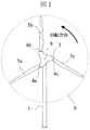
- the downwind type windmill according to the present embodiment is arranged on the tower 1 that supports the load generated in the entire windmill, and on the top of the tower 1, and the tower 1 is placed on the top of the tower 1.
- the nacelle 2 is supported so as to be rotatable with respect to the wind, a plurality of blades 5a, 5b, 5c for obtaining lift from the wind, and the nacelle 2 in order to use the lift of each blade 5a, 5b, 5c as rotational kinetic energy
- a rotor hub 3 that is rotatably supported, and bearings 4a, 4b, and 4c that connect the blades 5a, 5b, and 5c to the rotor hub 3, and each blade 5a on the leeward side of the tower 1 during power generation operation.
- the rotor hub 3 rotates with 5b and 5c positioned.
- the blades 5a, 5b and 5c are directly connected to the rotor hub 3 via bearings 4a, 4b and 4c.
- FIG. 1 shows a schematic structure of a downwind wind turbine according to this embodiment as viewed from the leeward side, as viewed from a direction orthogonal to the rotation surface 11 of the rotor 6 (axial direction of the rotor rotation shaft 8).
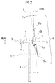
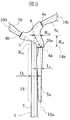
- FIG. 2 shows a schematic structure of the downwind type windmill from the side.
- the tower has a tower 1 extending almost vertically.
- the base on the lower side of the tower 1 is installed on the foundation if it is on land, and if it is offshore, it is joined to the foundation installed from the seabed, or to the floating foundation that floats near the sea surface.
- a rotor 6 is connected to the leeward side of the nacelle 2 via a main shaft.
- the nacelle 2 and the rotor 6 adjust the yaw angle by rotating around the tower central axis 7 of the tower 1.
- the nacelle 2 is provided with all or part of a generator, a power adjustment device, a power transmission mechanism, a cooling device, and sensors for measuring wind speed and direction.
- the rotor 6 mainly includes a rotor hub 3 and blades 5a, 5b, and 5c.
- the rotor hub 3 rotates around the rotor rotation shaft 8 and rotates counterclockwise when viewed from the leeward side during power generation in the wind turbine in this embodiment.
- the direction of rotation of the windmill is not limited to counterclockwise.
- the rotor rotation shaft 8 is inclined with respect to the horizontal plane 9 by the tilt angle ⁇ t , and therefore the rotor hub 3 that rotates about the rotor rotation shaft 8. Is also installed in a tilted state with respect to the horizontal plane 9.
- the tilt angle ⁇ t is set so that the tower 1 and the blades 5 a, 5 b, 5 c do not collide during rotation of the rotor 6.
- the rotor hub 3 and the blades 5a, 5b, and 5c are connected to each other through the bearings 4a, 4b, and 4c.
- the blades 5a, 5b, and 5c are rotatably supported with respect to the rotor hub 3 on the outer peripheral side of the rotor 6 by the bearings 4a, 4b, and 4c.
- FIG. 2 shows a bearing rotation shaft 10b that is a rotation shaft of the bearing 4b among the rotation shafts of the bearings 4a, 4b, and 4c with respect to the rotor hub 3.
- the cornering angle ⁇ c is determined by the angle formed by the rotor rotation surface 11 and the bearing rotation shaft 10 b, and the bearing rotation shaft 10 b is inclined away from the rotor rotation surface 11 and the nacelle 2. Since the blades 5a, 5b, and 5c are connected to the bearings 4a, 4b, and 4c, the blades 5a, 5b, and 5c are also inclined in the axial direction of the rotor rotation shaft 8.
- the cornering angle ⁇ c is set so as to avoid collision between the tower 1 and the blades 5a, 5b, and 5c while the rotor 6 is rotating.
- the blades 5a, 5b, and 5c are rotated by the bearings 4a, 4b, and 4c combined with the pitch angle control mechanism according to the operating state of the windmill.
- the blades 5a, 5b, and 5c are rotated by the bearings 4a, 4b, and 4c, and the rotational speed of the rotor 6 is controlled by adjusting the wind inflow angle to the blades 5a, 5b, and 5c.
- the bearings 4a, 4b, and 4c are inclined in the axial direction of the rotor rotating shaft 8 when the coning angle ⁇ c ⁇ 0 °, and therefore should be displayed in an inclined state from the viewpoint of FIG.
- the inclination of the coning angle ⁇ c is omitted (for simplicity, the coning angle ⁇ c is displayed at 0 °).
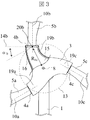
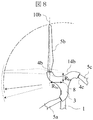
- FIG. 9 shows the structure around the bearing 4b.
- the bearing rotation surface 14b is a plane on which the bearing 4b rotates and a plane including the center of gravity of the bearing 4b.
- the point where the bearing rotating shaft 10b and the bearing rotating surface 14b are orthogonal to each other is defined as the rotation center point 20b of the bearing rotating surface 14b.
- the rotor hub 3 mainly includes a hub housing 15 and a spinner cover 16, and the outside of the hub housing 15 is covered by the spinner cover 16.
- Each bearing 4a, 4b, 4c is connected to the hub housing 15 of the rotor hub 3.
- the bearing mounting angle ⁇ b is represented as a contact angle of the bearing rotating surface 14b with respect to the circumference 13 around the rotor rotating shaft 8 of the rotor hub 3, and each bearing 4a, 4b, 4c in this embodiment is a bearing mounting angle. It is installed in a state inclined from the circumference 13 in the direction opposite to the rotation of the rotor 6 by ⁇ b .
- the circumference 13 includes the rotation center point 20b, and the distance from the rotor rotation shaft 8 to the rotation center point 20a (the radius of the circumference 13) is defined by Rbc . Further, although inclined in the opposite direction of rotation of the rotor 6 in FIG. 3, it may be inclined to the direction of rotation of the rotor 6 in the bearing mounting angle alpha b.
- blade support portions 19a, 19b, and 19c extend from the rotor rotation shaft 8 side to the blades 5a, 5b, and 5c, respectively. From the center of the hub housing 15 to the parts connected to the bearings 4a, 4b, and 4c, the material is continuous and has an integrated structure. Each blade support portion 19 a, 19 b, 19 c extends farther from the rotor rotation shaft 8 located at the rotation center of the rotor hub 3 than any portion of the hub housing 15.
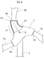
- the bearing provided from the rotor rotating shaft 8 of the rotor hub 3 to the tips of the blades 5a, 5b, and 5c is only one of the bearings 4a, 4b, and 4c.
- the bearings 4a, 4b, and 4c are bearings that are disposed at positions closest to the rotor rotation shaft 8 of the rotor hub 3.
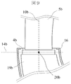
- FIG. 4 when a plane perpendicular to the rotor radial direction at the center of gravity of the (outer) cross section of the blade support portion 19b of the hub housing 15 is defined as an orthogonal plane 17 in the rotor radial direction, the hub housing 15 is a bearing.
- the (outer) cross-sectional area of the blade support portion 19b in the orthogonal plane 17 increases from the side connected to 4b (or the blade 5b side) toward the rotor rotation shaft 8 side.
- FIG. 5 shows the downwind type windmill in the present embodiment as viewed from the direction (axial direction of the rotor rotating shaft 8) perpendicular to the rotating surface 11 of the rotor 6 on the leeward side as in FIG.
- the tower central shaft 7 and the bearing rotating shaft 10a of the bearing 4a are arranged in parallel on the projection plane of FIG.
- R ba represents the distance from the rotor rotating shaft 8 to the bearing rotating shaft 10a
- R bc represents the distance from the rotor rotating shaft 8 to the rotation center point 20a
- R bs is defined by Equation 1.
- the bearing rotation shafts 10a, 10b, and 10c are inclined in the axial direction of the rotor rotation shaft 8, and therefore a straight line indicating R ba and a straight line indicating R bc Do not cross structurally.
- R ba is not less than (0.5D t + 0.5L b ) and not more than R bs .
- R bs inevitably becomes equal to or greater than (0.5D t + 0.5L b ) from the relationship of Equation 1.
- the rotor 6 starts rotating at a predetermined wind speed or higher, and the rotational speed increases as the wind speed increases. Further, the nacelle 2 and the rotor 6 adjust the yaw angle according to the change of the wind direction by the wind direction sensor provided in the nacelle 2 with the tower central axis 7 as an axis.
- the respective bearings 4a, 4b, and 4c combined with a pitch angle control mechanism (not shown) cause the blades 5a, 5b, and 5c to rotate around the bearing rotation shafts 10a, 10b, and 10c, and the blades 5a, 5b,
- the inflow angle of the wind to 5c is adjusted, and the amount of power generation is increased by increasing the rotational speed of the rotor 6.
- the angle may be further adjusted to approach a state close to feathering.
- the inflow angle of each blade 5a, 5b, 5c is adjusted to the state of complete feathering in order to stop the operation.
- FIG. 6 shows a wind speed distribution in the horizontal plane 12 (shown in FIG. 2) in a state where the tower 1 and the blade 5a overlap with the wind direction.
- the upstream side of the tower 1 has nothing to obstruct the flow, so that the wind flows with the wind speed distribution maintained to some extent.
- the flow is blocked by the tower 1 and a low wind speed region is generated.
- the blade 5a is in the low wind speed region.
- the blade 5a Since the blade 5a obtains lift from the fluid force of the wind and changes it into rotational kinetic energy, a large load corresponding to that is applied to the blade 5a. However, at the moment of entering the low wind speed region on the downstream side of the tower 1, the blade 5 a cannot obtain sufficient lift due to the low wind speed, and the load suddenly decreases. Then, at the moment of escaping from the low wind speed region on the downstream side of the tower 1, the wind speed is restored again, so that the lift of the blade 5a is also restored, and a large load is suddenly applied.
- the bearings 4a, 4b, 4c as shown in the bearing mounting angle alpha b, are disposed in a state inclined from the upper circumference 13 around the rotor shaft 8. Therefore, the blades 5a, 5b, and 5c connected to the bearings 4a, 4b, and 4c are also inclined from the circumference 13 around the rotor rotation shaft 8 (in the direction opposite to the rotation of the rotor 6). .
- the blades 5a, 5b, and 5c cross the downstream side of the tower 1, the entire length of the tower 1 and the blades 5a, 5b, and 5c do not overlap at the same time in the mainstream direction of the wind.
- Each blade 5a, 5b, 5c gradually overlaps with the tower 1 for each part of the blade region in accordance with the rotation of the rotor 6, thereby dispersing aerodynamic interference with the tower 1 and reducing the maximum load fluctuation.
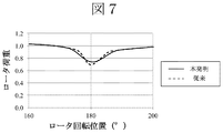
- FIG. 7 conceptually shows a change in load at an arbitrary portion of the rotor with respect to the rotor rotational position.
- a conventional general downwind wind turbine in which the tower and the blades are overlapped in the mainstream direction at the same time.
- the downwind type windmill according to the present embodiment is compared. Assuming that the rotor rotation position when the rotor blade reaches the highest point is 0 °, both the general downwind wind turbine and the downwind wind turbine according to this embodiment have a tower rotation position of 180 °. The blade crosses the downstream side.
- the rotor load “1” is the average load of the rotor. As shown in FIG.
- each of the bearings 4a, 4b, and 4c is inclined from the circumference 13 around the rotor rotation shaft 8, so that the blades 5a, 5b, and 5c are located downstream of the tower 1.
- the load fluctuation when traversing can be moderated.
- variation can be reduced as the whole windmill. That is, the reliability can be improved by reducing the load fluctuation applied to each blade 5a, 5b, 5c and the tower 1 when the wind turbine is used for a long time.
- the hub housing 15 is relatively large.
- placing the bearings 4a, 4b, and 4c in a state inclined by a bearing mounting angle alpha b, each bearing 4a, 4b, to the position of 4c simply expanding the circular hub housing that Is also possible.
- the hub housing increases in weight more than necessary, leading to an extra cost. Therefore, as in the present embodiment, the blade support portions 19a, 19b, 19c necessary for supporting the blades 5a, 5b, 5c are formed, and the blade support portions are more than any part of the hub housing 15.
- the load increases with approaching the rotation center side of the rotor of the wind turbine. Therefore, a large load is applied to the rotor hub 3 in the vicinity of the rotor rotation shaft 8 of the rotor 6.
- the hub housing 15 of the rotor hub 3 is a main part for transmitting the rotational kinetic energy of the rotor 6 to the main shaft on the rotor rotation shaft 8, the rotor hub 3 is a part on which a particularly large load is concentrated. . Therefore, in the structure shown in the present embodiment, the bearings 4a, 4b, and 4c that rotatably support the blades 5a, 5b, and 5c are provided directly to the hub housing 15, and extra bearings such as additional bearings are provided.
- Reliability is improved without using any other member. That is, the risk of failure can be greatly reduced by using only one bearing between the blades 5a, 5b, 5c and the rotation center of the rotor hub 3, as compared with a structure in which a plurality of bearings are arranged.
- each blade support portion 19a, 19b, 19c may be divided and bolted with a flange or the like in assembly. If only a large load is supported, a failure may occur in the fastening portion. A failure can be suppressed and avoided by forming the rotor hub 3 as an integral structure that is continuous in material from the center to a portion connected to each of the bearings 4a, 4b, and 4c. That is, the reliability can be further improved.
- each blade support portion 19a, 19b, 19c in order to suppress a significant increase in weight and cost, it is conceivable to simplify the structure of each blade support portion 19a, 19b, 19c. However, if the structure is inadvertently reduced, a load is locally applied. There is a risk of concentration and failure (damage).
- the outer shapes of the blade support portions 19a, 19b, and 19c are expanded from the side connected to the bearings 4a, 4b, and 4c toward the rotor rotating shaft 8 side. Therefore, local concentration of load can be avoided, and failure (breakage) can be suppressed and avoided.
- the total distance between the half of the distance of the average width L b in the chordwise half the distance and the blade 5a of the average width D t of the tower 1 (or 5b or 5c,), rotor rotation By setting the distance R ba from the shaft 8 to the bearing rotation shaft 10a to be equal to or greater than that, the tower 1 and the blade 5a (or 5b or 5c) can be prevented from overlapping, and the bearing 4a (or 4b or 4c). ) Can be further brought out of the effect of reducing load fluctuations.
- FIG. 8 shows a downwind type windmill in which the distance R bs is smaller than the distance R ba .
- the distance R bs is made smaller than the distance R ba by a solid line is shown.
- the diameter of the rotor 6 is expanded.
- the diameter of the rotor 6 is further increased by inverting the bearing rotating shaft 10b and the bearing rotating surface 14b as shown by the broken line in FIG. This makes it possible to further increase the amount of power generation. Therefore, by making the distance R ba equal to or less than the distance R bs , the effect of increasing the amount of power generation due to the diameter increase of the rotor 6 can be brought out by utilizing the structure of the rotor hub 3.
- the blades In downwind type wind turbines where blades are installed on the downstream side of the tower with respect to the wind direction, the blades cross the wake that occurs on the downstream side of the tower, so the upwind type has blades installed on the upstream side of the tower. Compared with the windmill, the load fluctuation is relatively large. Therefore, it becomes more suitable in applying the present invention.
- the scope of application of the present invention is not limited to the downwind wind turbine, and a certain effect can be expected even when it is applied to an upwind wind turbine in which the blades rotate while being positioned on the windward during power generation operation. it can. That is, even in an upwind type windmill, a load fluctuation occurs due to an increase in pressure between the blade and the tower due to aerodynamic interference, and the present invention may be implemented in an upwind type windmill. .
Landscapes
- Engineering & Computer Science (AREA)
- Life Sciences & Earth Sciences (AREA)
- Sustainable Development (AREA)
- Sustainable Energy (AREA)
- Chemical & Material Sciences (AREA)
- Combustion & Propulsion (AREA)
- Mechanical Engineering (AREA)
- General Engineering & Computer Science (AREA)
- Physics & Mathematics (AREA)
- Fluid Mechanics (AREA)
- Wind Motors (AREA)
Abstract
L'invention vise à proposer un dispositif de génération d'énergie éolienne avec lequel une fluctuation de charge peut être réduite. A cet effet, la présente invention est caractérisée en ce qu'elle comporte une tour, une nacelle disposée au sommet de la tour et portée de façon à être apte à tourner par rapport à la tour, un moyeu de rotor porté de façon être apte à tourner par rapport à la nacelle et comportant un boîtier de moyeu, des pales qui reçoivent du vent et qui produisent ainsi une force de soulèvement, et des paliers qui portent les pales de façon à être aptes à tourner par rapport au moyeu de rotor, les paliers étant disposés de façon inclinée par rapport à un cercle centré sur l'axe de rotation du moyeu de rotor.
Priority Applications (4)
| Application Number | Priority Date | Filing Date | Title |
|---|---|---|---|
| PCT/JP2013/062318 WO2014174654A1 (fr) | 2013-04-26 | 2013-04-26 | Dispositif de generation d'energie eolienne |
| EP13882716.7A EP2990642A4 (fr) | 2013-04-26 | 2013-04-26 | Dispositif de generation d'energie eolienne |
| JP2015513449A JPWO2014174654A1 (ja) | 2013-04-26 | 2013-04-26 | 風力発電装置 |
| TW103109567A TWI527962B (zh) | 2013-04-26 | 2014-03-14 | Wind power plant |
Applications Claiming Priority (1)
| Application Number | Priority Date | Filing Date | Title |
|---|---|---|---|
| PCT/JP2013/062318 WO2014174654A1 (fr) | 2013-04-26 | 2013-04-26 | Dispositif de generation d'energie eolienne |
Publications (1)
| Publication Number | Publication Date |
|---|---|
| WO2014174654A1 true WO2014174654A1 (fr) | 2014-10-30 |
Family
ID=51791260
Family Applications (1)
| Application Number | Title | Priority Date | Filing Date |
|---|---|---|---|
| PCT/JP2013/062318 WO2014174654A1 (fr) | 2013-04-26 | 2013-04-26 | Dispositif de generation d'energie eolienne |
Country Status (4)
| Country | Link |
|---|---|
| EP (1) | EP2990642A4 (fr) |
| JP (1) | JPWO2014174654A1 (fr) |
| TW (1) | TWI527962B (fr) |
| WO (1) | WO2014174654A1 (fr) |
Cited By (2)
| Publication number | Priority date | Publication date | Assignee | Title |
|---|---|---|---|---|
| WO2019074031A1 (fr) * | 2017-10-12 | 2019-04-18 | 株式会社日立製作所 | Aérogénérateur |
| JP2020070818A (ja) * | 2018-10-29 | 2020-05-07 | 三菱重工業株式会社 | 複列軸受 |
Citations (5)
| Publication number | Priority date | Publication date | Assignee | Title |
|---|---|---|---|---|
| JPS5783672A (en) * | 1980-11-12 | 1982-05-25 | Shin Meiwa Ind Co Ltd | Pitch control device of propeller type wind mill |
| JP2000310179A (ja) | 1999-04-27 | 2000-11-07 | Fuji Heavy Ind Ltd | 水平軸風車用ロータ |
| JP2004108162A (ja) | 2002-09-13 | 2004-04-08 | Mitsubishi Heavy Ind Ltd | 連環式翼通過面積調整装置を備えた風車及びその運転方法 |
| JP2010014105A (ja) * | 2008-07-03 | 2010-01-21 | Ryozo Ota | 風力発電装置 |
| WO2011081401A2 (fr) * | 2009-12-30 | 2011-07-07 | Jeen Mok Yoon | Éolienne |
Family Cites Families (4)
| Publication number | Priority date | Publication date | Assignee | Title |
|---|---|---|---|---|
| US1648837A (en) * | 1927-06-10 | 1927-11-08 | Anderson John | Power plant |
| US2054810A (en) * | 1933-12-16 | 1936-09-22 | Gaba Achille Ernest | Adjustable pitch propeller |
| US4183715A (en) * | 1978-02-01 | 1980-01-15 | First National Bank Of Lubbock | Adjustable vane windmills |
| ES2289082T3 (es) * | 2002-02-25 | 2008-02-01 | Iskra Wind Turbines Ltd. | Regulacion pasiva de velocidad y potencia de una turbina eolica. |
-
2013
- 2013-04-26 WO PCT/JP2013/062318 patent/WO2014174654A1/fr active Application Filing
- 2013-04-26 JP JP2015513449A patent/JPWO2014174654A1/ja not_active Abandoned
- 2013-04-26 EP EP13882716.7A patent/EP2990642A4/fr not_active Withdrawn
-
2014
- 2014-03-14 TW TW103109567A patent/TWI527962B/zh not_active IP Right Cessation
Patent Citations (5)
| Publication number | Priority date | Publication date | Assignee | Title |
|---|---|---|---|---|
| JPS5783672A (en) * | 1980-11-12 | 1982-05-25 | Shin Meiwa Ind Co Ltd | Pitch control device of propeller type wind mill |
| JP2000310179A (ja) | 1999-04-27 | 2000-11-07 | Fuji Heavy Ind Ltd | 水平軸風車用ロータ |
| JP2004108162A (ja) | 2002-09-13 | 2004-04-08 | Mitsubishi Heavy Ind Ltd | 連環式翼通過面積調整装置を備えた風車及びその運転方法 |
| JP2010014105A (ja) * | 2008-07-03 | 2010-01-21 | Ryozo Ota | 風力発電装置 |
| WO2011081401A2 (fr) * | 2009-12-30 | 2011-07-07 | Jeen Mok Yoon | Éolienne |
Non-Patent Citations (1)
| Title |
|---|
| See also references of EP2990642A4 * |
Cited By (2)
| Publication number | Priority date | Publication date | Assignee | Title |
|---|---|---|---|---|
| WO2019074031A1 (fr) * | 2017-10-12 | 2019-04-18 | 株式会社日立製作所 | Aérogénérateur |
| JP2020070818A (ja) * | 2018-10-29 | 2020-05-07 | 三菱重工業株式会社 | 複列軸受 |
Also Published As
| Publication number | Publication date |
|---|---|
| TW201508168A (zh) | 2015-03-01 |
| EP2990642A1 (fr) | 2016-03-02 |
| JPWO2014174654A1 (ja) | 2017-02-23 |
| TWI527962B (zh) | 2016-04-01 |
| EP2990642A4 (fr) | 2016-11-30 |
Similar Documents
| Publication | Publication Date | Title |
|---|---|---|
| JP7030711B2 (ja) | 効率を向上させた垂直軸ツインタービンを有する浮体式風力タービン | |
| US4784568A (en) | Wind turbine system using a vertical axis savonius-type rotor | |
| JP2013540934A (ja) | 最適化されたブレードを有し、風力および/または水力のために風/水を追跡するツインタービンシステム | |
| US20160312765A1 (en) | Vertical axis lift-driven wind turbine with force canceling blade configuration | |
| CA2892050C (fr) | Rotor de turbine eolienne et ses procedes d'assemblage | |
| US20200132044A1 (en) | Wind turbine | |
| WO2017110298A1 (fr) | Système d'éolienne et parc éolien | |
| WO2014174654A1 (fr) | Dispositif de generation d'energie eolienne | |
| JP3766845B2 (ja) | 風力発電装置 | |
| JP5543385B2 (ja) | 浮体式風力発電装置 | |
| KR102685496B1 (ko) | 로터 조립체 및 로터 조립체를 포함하는 풍차 | |
| JP5711500B2 (ja) | 風力発電装置 | |
| EP2879950A1 (fr) | Engin plus léger que l'air pour turbines de production d'énergie | |
| US11898534B2 (en) | Hinged blade wind turbine with tilted axis and/or coned rotor | |
| KR100979177B1 (ko) | 풍력 발전 장치 | |
| JP6887933B2 (ja) | 風力発電装置 | |
| JP2002349412A (ja) | 風力発電用風車及びその制御方法 | |
| JP7040792B2 (ja) | 揚力型垂直軸風水車 | |
| US20240141866A1 (en) | Cross-flow wind turbine with twin blades and inclined rotation axes | |
| JP2005036791A (ja) | 流体駆動回転子及び流体駆動式発電装置 | |
| JP6643615B2 (ja) | 風力発電機のティータ角制御装置 | |
| WO2024193781A1 (fr) | Éolienne à pas variable | |
| KR20130009937A (ko) | 날개각도 제어기능을 갖는 수직축 풍력발전시스템 | |
| KR20130025477A (ko) | 터빈 블레이드 및 이를 구비한 풍력 발전기 | |
| KR20120028500A (ko) | 날개각도 제어기능을 갖는 수직축 풍력발전시스템 |
Legal Events
| Date | Code | Title | Description |
|---|---|---|---|
| 121 | Ep: the epo has been informed by wipo that ep was designated in this application |
Ref document number: 13882716 Country of ref document: EP Kind code of ref document: A1 |
|
| ENP | Entry into the national phase |
Ref document number: 2015513449 Country of ref document: JP Kind code of ref document: A |
|
| NENP | Non-entry into the national phase |
Ref country code: DE |
|
| WWE | Wipo information: entry into national phase |
Ref document number: 2013882716 Country of ref document: EP |