WO2014174618A1 - 光源装置および車両用灯具 - Google Patents
光源装置および車両用灯具 Download PDFInfo
- Publication number
- WO2014174618A1 WO2014174618A1 PCT/JP2013/062113 JP2013062113W WO2014174618A1 WO 2014174618 A1 WO2014174618 A1 WO 2014174618A1 JP 2013062113 W JP2013062113 W JP 2013062113W WO 2014174618 A1 WO2014174618 A1 WO 2014174618A1
- Authority
- WO
- WIPO (PCT)
- Prior art keywords
- light source
- excitation light
- particles
- source device
- fluorescence
- Prior art date
- Legal status (The legal status is an assumption and is not a legal conclusion. Google has not performed a legal analysis and makes no representation as to the accuracy of the status listed.)
- Ceased
Links
Images



Classifications
-
- F—MECHANICAL ENGINEERING; LIGHTING; HEATING; WEAPONS; BLASTING
- F21—LIGHTING
- F21S—NON-PORTABLE LIGHTING DEVICES; SYSTEMS THEREOF; VEHICLE LIGHTING DEVICES SPECIALLY ADAPTED FOR VEHICLE EXTERIORS
- F21S41/00—Illuminating devices specially adapted for vehicle exteriors, e.g. headlamps
- F21S41/10—Illuminating devices specially adapted for vehicle exteriors, e.g. headlamps characterised by the light source
- F21S41/14—Illuminating devices specially adapted for vehicle exteriors, e.g. headlamps characterised by the light source characterised by the type of light source
- F21S41/16—Laser light sources
-
- F—MECHANICAL ENGINEERING; LIGHTING; HEATING; WEAPONS; BLASTING
- F21—LIGHTING
- F21S—NON-PORTABLE LIGHTING DEVICES; SYSTEMS THEREOF; VEHICLE LIGHTING DEVICES SPECIALLY ADAPTED FOR VEHICLE EXTERIORS
- F21S41/00—Illuminating devices specially adapted for vehicle exteriors, e.g. headlamps
- F21S41/10—Illuminating devices specially adapted for vehicle exteriors, e.g. headlamps characterised by the light source
- F21S41/14—Illuminating devices specially adapted for vehicle exteriors, e.g. headlamps characterised by the light source characterised by the type of light source
- F21S41/176—Light sources where the light is generated by photoluminescent material spaced from a primary light generating element
-
- F—MECHANICAL ENGINEERING; LIGHTING; HEATING; WEAPONS; BLASTING
- F21—LIGHTING
- F21S—NON-PORTABLE LIGHTING DEVICES; SYSTEMS THEREOF; VEHICLE LIGHTING DEVICES SPECIALLY ADAPTED FOR VEHICLE EXTERIORS
- F21S41/00—Illuminating devices specially adapted for vehicle exteriors, e.g. headlamps
- F21S41/20—Illuminating devices specially adapted for vehicle exteriors, e.g. headlamps characterised by refractors, transparent cover plates, light guides or filters
- F21S41/285—Refractors, transparent cover plates, light guides or filters not provided in groups F21S41/24 - F21S41/2805
Definitions
- the present invention relates to a light source device using a phosphor and an excitation light source.
- the present invention relates to a vehicular lamp using a laser light emitting element as an excitation light source.
- Patent Document 1 discloses a solid light source that emits light having a predetermined wavelength in a wavelength region from ultraviolet light to visible light, and a solid that is excited by excitation light from the solid light source.
- a light source device including a phosphor layer including at least one kind of phosphor that emits fluorescence having a wavelength longer than that of a light source.
- the solid light source and the phosphor layer are spatially separated from each other, and at least fluorescence is extracted from the surface of the phosphor layer on the side where the excitation light is incident by a reflection method.
- a light diffusing means for diffusing excitation light from a solid-state light source is provided on the surface on which light is incident.
- the excitation light reflected by the phosphor has angle dependency.
- the diffuse reflection component having no angle dependency can be used as illumination light by mixing with light emitted from a phosphor that also has no angle dependency.
- specular reflection components with strong directivity may cause uneven color of the emitted light, or may cause damage to human eyes when emitted outside with strong directivity. It cannot be a factor of energy loss.
- the specular reflection component is reduced by providing a concavo-convex structure having a light diffusing function on the surface of the phosphor layer on which the excitation light is incident.
- the concavo-convex structure is formed by processing the surface of the phosphor layer or arranging particulate substances on the surface of the phosphor layer.
- the phosphor particles may be damaged during processing to reduce the luminous efficiency of the phosphor.
- a phosphor with high excitation light absorption efficiency when used, most of the excitation light is absorbed by the phosphor, and the amount of excitation light that is diffusely reflected is insufficient, realizing the chromaticity necessary for a light source device. May be difficult to do.
- the particulate matter is arranged on the surface of the phosphor layer to form irregularities on the surface, the same problem as in the case of the above-described surface processing occurs when the particulate matter is the same material as the phosphor layer.
- the fluorescence emitted from the phosphor layer is scattered backward by the particulate matter on the surface and may not be taken out to the outside, resulting in energy loss.
- the present invention provides a light source device and a vehicular lamp that can reduce the energy loss and can design the emitted light to a desired chromaticity.
- the present invention includes a light source that emits excitation light and a fluorescent layer that emits fluorescence by excitation light from the light source, and the fluorescence emitted from the phosphor layer and the diffuse reflection by the phosphor layer.
- the phosphor layer includes a plurality of phosphor particles that emit fluorescence by the excitation light and a plurality of diffuse reflection particles that diffusely reflect the excitation light. Then, a plurality of phosphor particles and a plurality of diffuse reflection particles are dispersed in the phosphor layer.
- the present invention it is possible to provide a light source device and a vehicular lamp that have little energy loss and can design emitted light to a desired chromaticity.
- the diffuse reflection particles contained in the phosphor layer diffusely reflect the excitation light, and the amount of regular reflection can be reduced, so that energy loss can be reduced. Since the color mixing ratio of the fluorescence from the phosphor layer and the diffusely reflected excitation light can be adjusted by the amount of the diffuse reflection particles mixed, the emitted light can be designed to have a desired chromaticity.
- FIG. 1 is a perspective view showing a configuration of a vehicular lamp in Example 1.
- FIG. 3 is a cross-sectional view of a main part of a phosphor layer in Example 1.
- FIG. 6 is a cross-sectional view of a main part of a phosphor layer in Example 2.
- FIG. 6 is a cross-sectional view of a main part of a phosphor layer in Example 3.
- FIG. 6 is a cross-sectional view of a main part of a phosphor layer in Example 4.
- FIG. FIG. 6 is a cross-sectional view of a main part of a phosphor layer in Example 5.
- the constituent elements are not necessarily indispensable unless otherwise specified and clearly considered essential in principle. Needless to say.
- a vehicular lamp will be described as an example. As long as the light source device emits visible light.
- FIG. 1 is a perspective view showing a configuration of a vehicular lamp in the first embodiment.
- the vehicular lamp in the first embodiment is a so-called projector-type lamp, and includes a semiconductor light emitting element 1, a condenser lens 2, a phosphor layer 3, a metal plate 4, and a reflector 5.
- a laser diode (LD) is used for the semiconductor light emitting element 1 as a light source, and emits blue laser light as excitation light of the phosphor layer 3.
- the condenser lens 2 is disposed on the emission side of the semiconductor light emitting element 1 and condenses the excitation light (blue laser light) emitted from the semiconductor light emitting element 1 on the surface of the phosphor layer 3 disposed above.
- the reflector 5 is formed in a curved plate shape that opens obliquely forward and upward, and is disposed so as to face the lower side of the phosphor layer 3.
- the upper surface of the reflector 5 is a reflection surface 5a that reflects the fluorescence emitted from the phosphor layer 3 and the diffusely reflected excitation light forward.
- the reflecting surface 5a is formed into a free-form surface, for example, a shape based on a paraboloid so as to obtain a desired light distribution.
- the reflecting surface 5a is disposed so as to face the phosphor layer 3 from the rear to the lower side of the phosphor layer 3, and the fluorescence emitted from the phosphor layer 3 and the diffusely reflected excitation light are transmitted to the front of the vehicle. To irradiate.
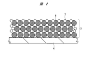
- FIG. 2 is a cross-sectional view of a main part of the phosphor layer in Example 1.
- the phosphor layer 3 in Example 1 includes a plurality of phosphor particles 6 and a plurality of diffuse reflection particles 7.
- the phosphor particle 6 is a fluorescent material that emits fluorescence when excited with blue light.
- Y 3 Al 5 O 12 Ce, Y 3 (Al, Ga) 5 O 12 : Ce, (Y, Gd) 3 Al 5 O 12 : Ce, (Y, Lu) 3 Al 5 O 12 : Ce, (Ba, Sr) 2 SiO 4 : Eu
- Ca 3 Sc 2 Si 3 O 12 Ce, (Ca, Sr) 2 Si 5 N 8 : Eu, (Ca, Sr) AlSiN 3 : Eu, Cax (Si, Al) 12 (O, N) 16 : Eu, (Si, Al) 6 (O, N) 8 : Eu, (Ba, Sr, Ca) Si 2 O 2 N 2 : Eu, Ca 8 MgSi 4 O 16 C 12 : Eu, SrAl 2 O 4 : Eu, Sr 4
- the diffuse reflection particle 7 is a material that diffusely reflects the excitation light and has little absorption with respect to the excitation light and the fluorescence from the phosphor particles 6.
- a light-transmitting material can be used.
- the reflecting surface with respect to the incident direction of the excitation light is random for each particle, so that the reflecting direction is also random, and uniform diffuse reflection can be realized.
- Some excitation light and fluorescence travel from the surface of the phosphor layer 3 toward the inside, but are reflected by the diffuse reflection particles 7 inside the phosphor layer 3 to the surface of the phosphor layer 3, so that the efficiency is high. Excitation light and fluorescence can be extracted and energy loss can be reduced.
- the ratio of the diffusely reflected excitation light to the fluorescence can be adjusted by the mixing amount of the diffusely reflecting particles 7.
- Example 1 a material that is transparent to excitation light and fluorescence is used as the diffuse reflection particle 7, but it is reflective to excitation light and fluorescence such as Al, Ag, and Pt. Materials can also be used.
- the phosphor particles 6 and the diffuse reflection particles 7 are mixed at a predetermined ratio, and pressed with a press to form a pellet. Subsequently, the pellet is heated in a heating furnace and sintered. The sintered pellet is fixed to the metal plate 4 using an adhesive, double-sided tape, metal solder joint, or the like.
- the amount of regular reflection of the excitation light can be reduced to reduce energy loss. Further, since the color mixing ratio between the fluorescence from the phosphor layer 3 and the diffusely reflected excitation light can be adjusted by the mixing amount of the diffuse reflection particles 7, the emitted light can be designed to have a desired chromaticity.
- Example 2 describes an example of a vehicle lamp that can handle high output in the vehicle lamp described in Example 1.
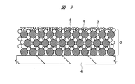
- FIG. 3 is a cross-sectional view of the main part of the phosphor layer in Example 2. Note that the configuration of the vehicular lamp according to the second embodiment is the same as that of the first embodiment shown in FIG.
- the phosphor layer 3 in Example 1 is composed of a plurality of phosphor particles 6, a plurality of diffuse reflection particles 7, and a plurality of surface heat conductive materials 8.
- the phosphor particle 6 is a fluorescent material that emits fluorescence when excited with blue light.
- Y 3 Al 5 O 12 Ce, Y 3 (Al, Ga) 5 O 12 : Ce, (Y, Gd) 3 Al 5 O 12 : Ce, (Y, Lu) 3 Al 5 O 12 : Ce, (Ba, Sr) 2 SiO 4 : Eu, Ca 3 Sc 2 Si 3 O 12 : Ce, (Ca, Sr) 2 Si 5 N 8 : Eu, (Ca, Sr) AlSiN 3 : Eu, Cax (Si, Al) 12 (O, N) 16 : Eu, (Si, Al) 6 (O, N) 8 : Eu, (Ba, Sr, Ca) Si 2 O 2 N 2 : Eu, Ca 8 MgSi 4 O 16 C 12 : Eu, SrAl 2 O 4 : Eu, Sr 4 Al 14 O 25 : Eu, (Ca, Sr) S: Eu, ZnS: Cu , Al, CaGa 2 S 4: Eu, SrG 2 S 4: Eu or the like can be used.
- the diffuse reflection particle 7 is a material that diffusely reflects the excitation light and has little absorption with respect to the excitation light and the fluorescence from the phosphor particles 6.
- a light-transmitting material can be used.
- the reflecting surface with respect to the incident direction of the excitation light is random for each particle, so that the reflecting direction is also random, and uniform diffuse reflection can be realized.
- Some excitation light and fluorescence travel from the surface of the phosphor layer 3 toward the inside, but are reflected by the diffuse reflection particles 7 inside the phosphor layer 3 to the surface of the phosphor layer 3, so that the efficiency is high. Excitation light and fluorescence can be extracted and energy loss can be reduced.
- the ratio of the diffusely reflected excitation light to the fluorescence can be adjusted by the mixing amount of the diffusely reflecting particles 7.
- Example 2 a material that is transparent to excitation light and fluorescence is used as the diffuse reflection particle 7, but it is reflective to excitation light and fluorescence such as Al, Ag, and Pt. Materials can also be used.
- the surface heat conductive material 8 is formed on the surface of the phosphor layer 3, and in particular, is formed so as to cover the surface of the phosphor particles 6.
- the surface thermal conductive material 8 is a material having high thermal conductivity and translucency with respect to excitation light and fluorescence from the phosphor particles 6.
- Al 2 O 3, MgO can be used SiO 2, TiO 2, BaSO 4 , SrTiO 4, Y 2 O 3, La 2 O 3, Y 3 Al 5 O 12, diamond, various transparent glass.
- the same thing as the diffuse reflection particle 7 may be included.
- the surface heat conductive material 8 may be in the form of particles or a film.
- a part of the energy of the excitation light absorbed by the phosphor particles 6 is emitted as fluorescence.
- the energy of the remaining excitation light is mainly heat, which raises the temperature of the phosphor particles 6 and causes a decrease in fluorescence efficiency due to temperature quenching.
- the heat of the phosphor particles 6 is dissipated to the air that contacts the surface of the phosphor particles 6 and the adjacent particles.
- the thermal conductivity of air is poor and the contact area between the adjacent particles is small, the heat dissipation amount is small.
- the energy of excitation light that can be input in a small amount is limited, and the illumination output is limited.
- the surface heat conductive material 8 covers the surface on the side where the density of the excitation light irradiated on the phosphor particles 6 is high. Since the surface heat conductive material 8 has high thermal conductivity, the heat generated on the surface of the phosphor particles 6 can be dispersed and dissipated to suppress the temperature rise of the phosphor particles 6.
- the phosphor particles 6 and the diffuse reflection particles 7 are mixed at a predetermined ratio, and pressed with a press to form a pellet. Thereafter, the surface heat conductive material 8 is formed on the surface of the pellets using a method such as printing, coating, dipping, vapor deposition or the like.
- the pellet having the surface heat conductive material 8 formed on the surface is heated in a heating furnace and sintered.
- the sintered pellet is fixed to the metal plate 4 using an adhesive, double-sided tape, metal solder joint, or the like.
- Example 2 the surface heat conductive material 8 is formed only on the surface of the phosphor layer 3, but the surface of the phosphor particles 6 located on the surface of the phosphor layer 3 is the surface heat conductive material 8.
- the surface heat conductive material 8 may be dispersed inside the phosphor layer 3.
- Example 3 describes an example of a vehicular lamp that can use a phosphor material or a diffuse reflection material with low moisture resistance in the vehicular lamp described in the first embodiment.
- FIG. 4 is a cross-sectional view of the main part of the phosphor layer in Example 3. Note that the configuration of the vehicular lamp in the third embodiment is the same as that of the first embodiment shown in FIG.
- the phosphor layer 3 in Example 3 includes a plurality of phosphor particles 6, a plurality of diffuse reflection particles 7, and a gap filling material 9.
- the phosphor particle 6 is a fluorescent material that emits fluorescence when excited with blue light.
- Y 3 Al 5 O 12 Ce, Y 3 (Al, Ga) 5 O 12 : Ce, (Y, Gd) 3 Al 5 O 12 : Ce, (Y, Lu) 3 Al 5 O 12 : Ce, (Ba, Sr) 2 SiO 4 : Eu
- the diffuse reflection particle 7 is a material that diffusely reflects the excitation light and has little absorption with respect to the excitation light and the fluorescence from the phosphor particles 6.
- excitation light and fluorescence of Al 2 O 3 , MgO, SiO 2 , TiO 2 , BaSO 4 , SrTiO 4 , Y 2 O 3 , La 2 O 3 , Y 3 Al 5 O 12 , diamond, various transparent glasses, etc.
- a material having a refractive index different from that of the space filling material 9 can be used.
- the reflecting surface with respect to the incident direction of the excitation light is random for each particle, so that the reflecting direction is also random, and uniform diffuse reflection can be realized.
- Some excitation light and fluorescence travel from the surface of the phosphor layer 3 toward the inside, but are reflected by the diffuse reflection particles 7 inside the phosphor layer 3 to the surface of the phosphor layer 3, so that the efficiency is high. Excitation light and fluorescence can be extracted and energy loss can be reduced.
- the ratio of the diffusely reflected excitation light to the fluorescence can be adjusted by the mixing amount of the diffusely reflecting particles 7.
- Example 3 a material that is transparent to excitation light and fluorescence is used as the diffuse reflection particle 7, but it is reflective to excitation light and fluorescence such as Al, Ag, and Pt. Materials can also be used.
- the space filling material 9 is formed so as to fill the space between the phosphor particles 6 and the diffuse reflection particles 7 in the phosphor layer 3 so that the phosphor particles 6 and the diffuse reflection particles 7 do not touch the air. Is formed.
- the space filling material 9 is a material having a low humidity transmittance and translucency with respect to excitation light and fluorescence from the phosphor particles 6.
- a silicone resin or an epoxy resin can be used.
- Some phosphor materials have light emission characteristics that deteriorate due to humidity. Some diffuse reflection materials change in quality due to humidity and exhibit absorbency with respect to excitation light or fluorescence. Therefore, by covering the surfaces of the phosphor particles 6 and the diffuse reflection material 7 with a space filling material 9 having a low humidity transmittance, deterioration of the phosphor material and alteration of the diffuse reflection material are suppressed.
- the phosphor particles 6 and the diffuse reflection particles 7 are mixed at a predetermined ratio, and pressed with a press to form a pellet. Subsequently, the pellet is heated in a heating furnace and sintered. After the sintered pellet is immersed in the space filling material 9 before curing, vacuum degassing is performed to fill the space in the pellet with the space filling material 9. The space-filling material 9 is cured by heating the pellets filled with the space-filling material 9. Thereafter, the pellet is fixed to the metal plate 4 using an adhesive, double-sided tape, metal solder bonding, or the like.
- Example 4 describes an example of a vehicle lamp that can use a phosphor material or a diffuse reflection material that is altered by the sintering process in the vehicle lamp described in Example 1.
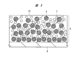
- FIG. 5 is a cross-sectional view of the main part of the phosphor layer in Example 4. Note that the configuration of the vehicular lamp in the fourth embodiment is the same as that of the first embodiment shown in FIG.
- the phosphor layer 3 in Example 4 includes a plurality of phosphor particles 6, a plurality of diffuse reflection particles 7, and a binder 10.
- the phosphor particle 6 is a fluorescent material that emits fluorescence when excited with blue light.
- Y 3 Al 5 O 12 Ce, Y 3 (Al, Ga) 5 O 12 : Ce, (Y, Gd) 3 Al 5 O 12 : Ce, (Y, Lu) 3 Al 5 O 12 : Ce, (Ba, Sr) 2 SiO 4 : Eu
- the diffuse reflection particle 7 is a material that diffusely reflects the excitation light and has little absorption with respect to the excitation light and the fluorescence from the phosphor particles 6.
- excitation light and fluorescence of Al 2 O 3 , MgO, SiO 2 , TiO 2 , BaSO 4 , SrTiO 4 , Y 2 O 3 , La 2 O 3 , Y 3 Al 5 O 12 , diamond, various transparent glasses, etc.
- a material having a refractive index different from that of the binder 10 can be used.
- a part of the excitation light incident on the diffuse reflection particle 7 is reflected by the difference in refractive index between the surface of the diffuse reflection particle 7 and the binder 10.
- the reflecting surface with respect to the incident direction of the excitation light is random for each particle, so that the reflecting direction is also random, and uniform diffuse reflection can be realized.
- Some excitation light and fluorescence travel from the surface of the phosphor layer 3 toward the inside, but are reflected by the diffuse reflection particles 7 inside the phosphor layer 3 to the surface of the phosphor layer 3, so that the efficiency is high. Excitation light and fluorescence can be extracted and energy loss can be reduced.
- the ratio of the diffusely reflected excitation light to the fluorescence can be adjusted by the mixing amount of the diffusely reflecting particles 7.
- Example 4 a material that is transparent to excitation light and fluorescence is used as the diffuse reflection particle 7, but it is reflective to excitation light and fluorescence such as Al, Ag, and Pt. Materials can also be used.
- the phosphor particles 6 and the diffuse reflection particles 7 are held on the metal plate 4 by the binder 10.
- the binder 10 is a material that is transparent to excitation light and fluorescence, and can hold the phosphor particles 6 and the diffuse reflection particles 7 on the metal plate 4 by a relatively low temperature process. Resin, low melting point glass, or the like can be used.
- thermosetting silicone resin used as the binder 10
- the phosphor particles 6, the diffuse reflection particles 7 and the binder 10 are mixed at a predetermined ratio to form a paste. After applying the paste on the metal plate 4, the binder 10 is cured by heating.
- Some phosphor materials have light emission characteristics that deteriorate due to a heating process above a certain temperature.
- some diffuse reflection materials are altered by heating at a temperature higher than a certain temperature, and absorb light with respect to excitation light or fluorescence. For this reason, when the pellet in which the phosphor particles 6 and the diffuse reflection particles 7 are mixed as in Example 1, the phosphor material or the diffuse reflection material may be altered depending on the temperature at the time of sintering. Therefore, by using the binder 10 to hold the phosphor particles 6 and the diffuse reflection particles 7 in a relatively low temperature process, alteration of the phosphor material and the diffuse reflection material is suppressed.
- Example 5 describes an example of a vehicle lamp that can further reduce regular reflection of excitation light on the phosphor layer surface in the vehicle lamp described in Example 3.
- FIG. 6 is a cross-sectional view of the main part of the phosphor layer in Example 5. Note that the configuration of the vehicular lamp in the fifth embodiment is the same as that of the first embodiment shown in FIG. Further, the configuration of the phosphor layer is the same as that of the third embodiment shown in FIG.
- the antireflection film 11 is formed on the surface of the phosphor layer 3.
- the antireflection film 11 suppresses surface reflection with respect to excitation light incident on the phosphor layer 3, and is, for example, an antireflection film using a transparent oxide, an AR (Anti Reflection) film, or the like.
- the antireflection film 11 is formed on the surface of the phosphor layer 3 by, for example, vapor deposition, coating, film pasting, or the like.
- the surface of the pellet becomes flat, and excitation light is emitted at the boundary between the space filling material 9 and air. Regular reflection may increase. Therefore, the regular reflection of the excitation light is suppressed by providing the antireflection film 11 on the surface of the phosphor layer 3.
- the antireflection film 11 is formed on the surface of the phosphor layer 3 described in the third embodiment.
- the bothersome prevention film 11 is also formed on the surface of the phosphor 3 described in the first, second, and fourth embodiments. You can also.
Landscapes
- Engineering & Computer Science (AREA)
- General Engineering & Computer Science (AREA)
- Physics & Mathematics (AREA)
- Optics & Photonics (AREA)
- Non-Portable Lighting Devices Or Systems Thereof (AREA)
- Led Device Packages (AREA)
- Semiconductor Lasers (AREA)
Abstract
Description
2 集光レンズ
3 蛍光体層
4 金属プレート
5 リフレクタ
5a 反射面
6 蛍光体粒子
7 拡散反射粒子
8 表面熱伝導材料
9 空間充填材料
10 バインダ
11 反射防止膜
Claims (13)
- 励起光を発する光源と、
前記励起光により蛍光を発する蛍光体層と、を備え、
前記蛍光体層から発せられた前記蛍光と、前記蛍光体層で拡散反射された前記励起光とを混色して照明光を出射する光源装置であって、
前記蛍光体層は、
前記励起光により前記蛍光を発する複数の蛍光体粒子と、
前記励起光を拡散反射する複数の拡散反射粒子と、を含み、
前記蛍光体層に前記複数の蛍光体粒子と前記複数の拡散反射粒子が分散されている、光源装置。 - 請求項1記載の光源装置において、
前記蛍光体層は、前記複数の蛍光体粒子と前記複数の拡散反射粒子とを混合し、焼結することにより形成される、光源装置。 - 請求項2記載の光源装置において、
前記複数の拡散反射粒子は、前記励起光および前記蛍光に対して透光性の材料である、光源装置。 - 請求項2記載の光源装置において、
前記複数の拡散反射粒子は、前記励起光および前記蛍光に対して反射性の材料である、光源装置。 - 請求項2記載の光源装置において、
前記蛍光体層の表面が、前記励起光および前記蛍光に対して透光性を有し、且つ熱伝導性を有する材料によって被覆され、
前記複数の蛍光体粒子が、前記蛍光層の表面に露出していない、光源装置。 - 請求項1記載の光源装置において、
前記蛍光体層は、前記複数の蛍光体粒子と前記複数の拡散反射粒子とを混合し、焼結することにより形成され、
前記複数の蛍光体粒子と前記複数の拡散反射粒子との空隙が、前記励起光および前記蛍光に対して透光性の充填材料で充填されている、光源装置。 - 請求項6記載の光源装置において、
前記複数の拡散反射粒子は、前記励起光および前記蛍光に対して透光性であり、且つ前記充填材料よりも屈折率が高い材料である、光源装置。 - 請求項6記載の光源装置において、
前記複数の拡散反射粒子は、前記励起光および前記蛍光に対して反射性の材料である、光源装置。 - 請求項1記載の光源装置において、
前記複数の蛍光体粒子と前記複数の拡散反射粒子が、前記励起光および前記蛍光に対して透光性の充填材料中に分散している、光源装置。 - 請求項9記載の光源装置において、
前記複数の拡散反射粒子は、前記励起光および前記蛍光に対して透光性であり、且つ前記充填材料よりも屈折率が高い材料である、光源装置。 - 請求項9記載の光源装置において、
前記複数の拡散反射粒子は、前記励起光および前記蛍光に対して反射性の材料である、光源装置。 - 請求項1~11のいずれか1項に記載の光源装置において、
前記蛍光体層の表面に前記励起光に対する反射防止膜が形成されている、光源装置。 - 光源装置を用いた車両用灯具であって、
前記光源装置は、
励起光を発する光源と、
前記励起光により蛍光を発する蛍光体層と、を備え、
前記蛍光体層から発せられた前記蛍光と、前記蛍光体層で拡散反射された前記励起光とが混色した照明光を出射し、
前記蛍光体層は、
前記励起光により前記蛍光を発する複数の蛍光体粒子と、
前記励起光を拡散反射する複数の拡散反射粒子と、を含み、
前記蛍光体層に前記複数の蛍光体粒子と前記複数の拡散反射粒子が分散されている、車両用灯具。
Priority Applications (4)
| Application Number | Priority Date | Filing Date | Title |
|---|---|---|---|
| US14/785,929 US20160102819A1 (en) | 2013-04-24 | 2013-04-24 | Light source device and vehicle lamp |
| CN201380075909.7A CN105190163A (zh) | 2013-04-24 | 2013-04-24 | 光源装置以及车辆用灯具 |
| JP2015513418A JPWO2014174618A1 (ja) | 2013-04-24 | 2013-04-24 | 光源装置および車両用灯具 |
| PCT/JP2013/062113 WO2014174618A1 (ja) | 2013-04-24 | 2013-04-24 | 光源装置および車両用灯具 |
Applications Claiming Priority (1)
| Application Number | Priority Date | Filing Date | Title |
|---|---|---|---|
| PCT/JP2013/062113 WO2014174618A1 (ja) | 2013-04-24 | 2013-04-24 | 光源装置および車両用灯具 |
Publications (1)
| Publication Number | Publication Date |
|---|---|
| WO2014174618A1 true WO2014174618A1 (ja) | 2014-10-30 |
Family
ID=51791226
Family Applications (1)
| Application Number | Title | Priority Date | Filing Date |
|---|---|---|---|
| PCT/JP2013/062113 Ceased WO2014174618A1 (ja) | 2013-04-24 | 2013-04-24 | 光源装置および車両用灯具 |
Country Status (4)
| Country | Link |
|---|---|
| US (1) | US20160102819A1 (ja) |
| JP (1) | JPWO2014174618A1 (ja) |
| CN (1) | CN105190163A (ja) |
| WO (1) | WO2014174618A1 (ja) |
Cited By (6)
| Publication number | Priority date | Publication date | Assignee | Title |
|---|---|---|---|---|
| WO2017110031A1 (ja) * | 2015-12-24 | 2017-06-29 | パナソニックIpマネジメント株式会社 | 発光素子および照明装置 |
| JP2017139072A (ja) * | 2016-02-01 | 2017-08-10 | シャープ株式会社 | 発光部および照明装置 |
| WO2017154807A1 (ja) * | 2016-03-08 | 2017-09-14 | パナソニックIpマネジメント株式会社 | 光源装置 |
| WO2017169187A1 (ja) * | 2016-03-31 | 2017-10-05 | ソニー株式会社 | 光源装置および電子機器 |
| JP2017194523A (ja) * | 2016-04-19 | 2017-10-26 | キヤノン株式会社 | 光源装置および画像投射装置 |
| CN115183202A (zh) * | 2022-07-20 | 2022-10-14 | 厦门大学 | 一种漫反射式激光照明装置 |
Families Citing this family (104)
| Publication number | Priority date | Publication date | Assignee | Title |
|---|---|---|---|---|
| US9902320B2 (en) | 2013-11-21 | 2018-02-27 | Ford Global Technologies, Llc | Photoluminescent color changing dome map lamp |
| US9905743B2 (en) | 2013-11-21 | 2018-02-27 | Ford Global Technologies, Llc | Printed LED heat sink double lock |
| US9950658B2 (en) | 2013-11-21 | 2018-04-24 | Ford Global Technologies, Llc | Privacy window system |
| US10400978B2 (en) | 2013-11-21 | 2019-09-03 | Ford Global Technologies, Llc | Photoluminescent lighting apparatus for vehicles |
| US9539940B2 (en) | 2013-11-21 | 2017-01-10 | Ford Global Technologies, Llc | Illuminated indicator |
| US9931991B2 (en) | 2013-11-21 | 2018-04-03 | Ford Global Technologies, Llc | Rotating garment hook |
| US10064256B2 (en) | 2013-11-21 | 2018-08-28 | Ford Global Technologies, Llc | System and method for remote activation of vehicle lighting |
| US9961745B2 (en) | 2013-11-21 | 2018-05-01 | Ford Global Technologies, Llc | Printed LED rylene dye welcome/farewell lighting |
| US10041650B2 (en) | 2013-11-21 | 2018-08-07 | Ford Global Technologies, Llc | Illuminated instrument panel storage compartment |
| US9810401B2 (en) | 2013-11-21 | 2017-11-07 | Ford Global Technologies, Llc | Luminescent trim light assembly |
| US10363867B2 (en) | 2013-11-21 | 2019-07-30 | Ford Global Technologies, Llc | Printed LED trim panel lamp |
| US9989216B2 (en) | 2013-11-21 | 2018-06-05 | Ford Global Technologies, Llc | Interior exterior moving designs |
| US10168039B2 (en) | 2015-08-10 | 2019-01-01 | Ford Global Technologies, Llc | Illuminated badge for a vehicle |
| US9889791B2 (en) | 2015-12-01 | 2018-02-13 | Ford Global Technologies, Llc | Illuminated badge for a vehicle |
| US10023100B2 (en) | 2015-12-14 | 2018-07-17 | Ford Global Technologies, Llc | Illuminated trim assembly |
| US10501007B2 (en) | 2016-01-12 | 2019-12-10 | Ford Global Technologies, Llc | Fuel port illumination device |
| US10235911B2 (en) | 2016-01-12 | 2019-03-19 | Ford Global Technologies, Llc | Illuminating badge for a vehicle |
| US10300843B2 (en) | 2016-01-12 | 2019-05-28 | Ford Global Technologies, Llc | Vehicle illumination assembly |
| CN106969305B (zh) * | 2016-01-14 | 2020-08-25 | 深圳光峰科技股份有限公司 | 一种可调节的光源装置及照明装置 |
| US10011219B2 (en) | 2016-01-18 | 2018-07-03 | Ford Global Technologies, Llc | Illuminated badge |
| US9927114B2 (en) | 2016-01-21 | 2018-03-27 | Ford Global Technologies, Llc | Illumination apparatus utilizing conductive polymers |
| US10189401B2 (en) | 2016-02-09 | 2019-01-29 | Ford Global Technologies, Llc | Vehicle light strip with optical element |
| US10501025B2 (en) | 2016-03-04 | 2019-12-10 | Ford Global Technologies, Llc | Vehicle badge |
| US10118568B2 (en) | 2016-03-09 | 2018-11-06 | Ford Global Technologies, Llc | Vehicle badge having discretely illuminated portions |
| US9963001B2 (en) | 2016-03-24 | 2018-05-08 | Ford Global Technologies, Llc | Vehicle wheel illumination assembly using photoluminescent material |
| US10081296B2 (en) | 2016-04-06 | 2018-09-25 | Ford Global Technologies, Llc | Illuminated exterior strip with photoluminescent structure and retroreflective layer |
| US9902315B2 (en) | 2016-04-15 | 2018-02-27 | Ford Global Technologies, Llc | Photoluminescent lighting apparatus for vehicles |
| US10064259B2 (en) | 2016-05-11 | 2018-08-28 | Ford Global Technologies, Llc | Illuminated vehicle badge |
| US10420189B2 (en) | 2016-05-11 | 2019-09-17 | Ford Global Technologies, Llc | Vehicle lighting assembly |
| US10631373B2 (en) | 2016-05-12 | 2020-04-21 | Ford Global Technologies, Llc | Heated windshield indicator |
| US9896020B2 (en) | 2016-05-23 | 2018-02-20 | Ford Global Technologies, Llc | Vehicle lighting assembly |
| US9994144B2 (en) | 2016-05-23 | 2018-06-12 | Ford Global Technologies, Llc | Illuminated automotive glazings |
| US9925917B2 (en) | 2016-05-26 | 2018-03-27 | Ford Global Technologies, Llc | Concealed lighting for vehicles |
| CN107450261B (zh) * | 2016-05-31 | 2021-02-05 | 佳能株式会社 | 波长转换元件、光源装置和图像投影装置 |
| US9937855B2 (en) | 2016-06-02 | 2018-04-10 | Ford Global Technologies, Llc | Automotive window glazings |
| US9803822B1 (en) * | 2016-06-03 | 2017-10-31 | Ford Global Technologies, Llc | Vehicle illumination assembly |
| US10343622B2 (en) | 2016-06-09 | 2019-07-09 | Ford Global Technologies, Llc | Interior and exterior iridescent vehicle appliques |
| US10205338B2 (en) | 2016-06-13 | 2019-02-12 | Ford Global Technologies, Llc | Illuminated vehicle charging assembly |
| US10131237B2 (en) | 2016-06-22 | 2018-11-20 | Ford Global Technologies, Llc | Illuminated vehicle charging system |
| US9855888B1 (en) | 2016-06-29 | 2018-01-02 | Ford Global Technologies, Llc | Photoluminescent vehicle appliques |
| US9840191B1 (en) | 2016-07-12 | 2017-12-12 | Ford Global Technologies, Llc | Vehicle lamp assembly |
| US9855797B1 (en) | 2016-07-13 | 2018-01-02 | Ford Global Technologies, Llc | Illuminated system for a vehicle |
| US9889801B2 (en) | 2016-07-14 | 2018-02-13 | Ford Global Technologies, Llc | Vehicle lighting assembly |
| US9840193B1 (en) | 2016-07-15 | 2017-12-12 | Ford Global Technologies, Llc | Vehicle lighting assembly |
| US9845047B1 (en) | 2016-08-08 | 2017-12-19 | Ford Global Technologies, Llc | Light system |
| US9827903B1 (en) | 2016-08-18 | 2017-11-28 | Ford Global Technologies, Llc | Illuminated trim panel |
| US10173604B2 (en) | 2016-08-24 | 2019-01-08 | Ford Global Technologies, Llc | Illuminated vehicle console |
| US10047911B2 (en) | 2016-08-31 | 2018-08-14 | Ford Global Technologies, Llc | Photoluminescent emission system |
| US10047659B2 (en) | 2016-08-31 | 2018-08-14 | Ford Global Technologies, Llc | Photoluminescent engine indicium |
| US10308175B2 (en) | 2016-09-08 | 2019-06-04 | Ford Global Technologies, Llc | Illumination apparatus for vehicle accessory |
| US10075013B2 (en) | 2016-09-08 | 2018-09-11 | Ford Global Technologies, Llc | Vehicle apparatus for charging photoluminescent utilities |
| US9863171B1 (en) | 2016-09-28 | 2018-01-09 | Ford Global Technologies, Llc | Vehicle compartment |
| US10046688B2 (en) | 2016-10-06 | 2018-08-14 | Ford Global Technologies, Llc | Vehicle containing sales bins |
| US9914390B1 (en) | 2016-10-19 | 2018-03-13 | Ford Global Technologies, Llc | Vehicle shade assembly |
| US10086700B2 (en) | 2016-10-20 | 2018-10-02 | Ford Global Technologies, Llc | Illuminated switch |
| US10035473B2 (en) | 2016-11-04 | 2018-07-31 | Ford Global Technologies, Llc | Vehicle trim components |
| US9902314B1 (en) | 2016-11-17 | 2018-02-27 | Ford Global Technologies, Llc | Vehicle light system |
| US9994089B1 (en) | 2016-11-29 | 2018-06-12 | Ford Global Technologies, Llc | Vehicle curtain |
| US10220784B2 (en) | 2016-11-29 | 2019-03-05 | Ford Global Technologies, Llc | Luminescent windshield display |
| KR20180063541A (ko) * | 2016-12-02 | 2018-06-12 | 엘지전자 주식회사 | 다결정 형광막 및 그 제조 방법 및 그를 이용한 차량 램프 장치 |
| US10118538B2 (en) | 2016-12-07 | 2018-11-06 | Ford Global Technologies, Llc | Illuminated rack |
| US10106074B2 (en) | 2016-12-07 | 2018-10-23 | Ford Global Technologies, Llc | Vehicle lamp system |
| US10422501B2 (en) | 2016-12-14 | 2019-09-24 | Ford Global Technologies, Llc | Vehicle lighting assembly |
| US10700242B2 (en) * | 2016-12-27 | 2020-06-30 | Nichia Corporation | Method of producing wavelength conversion member |
| US10144365B2 (en) | 2017-01-10 | 2018-12-04 | Ford Global Technologies, Llc | Vehicle badge |
| US9815402B1 (en) | 2017-01-16 | 2017-11-14 | Ford Global Technologies, Llc | Tailgate and cargo box illumination |
| US10173582B2 (en) | 2017-01-26 | 2019-01-08 | Ford Global Technologies, Llc | Light system |
| US10053006B1 (en) | 2017-01-31 | 2018-08-21 | Ford Global Technologies, Llc | Illuminated assembly |
| US9896023B1 (en) | 2017-02-09 | 2018-02-20 | Ford Global Technologies, Llc | Vehicle rear lighting assembly |
| US10427593B2 (en) | 2017-02-09 | 2019-10-01 | Ford Global Technologies, Llc | Vehicle light assembly |
| US9849829B1 (en) | 2017-03-02 | 2017-12-26 | Ford Global Technologies, Llc | Vehicle light system |
| US10240737B2 (en) | 2017-03-06 | 2019-03-26 | Ford Global Technologies, Llc | Vehicle light assembly |
| US10150396B2 (en) | 2017-03-08 | 2018-12-11 | Ford Global Technologies, Llc | Vehicle cup holder assembly with photoluminescent accessory for increasing the number of available cup holders |
| US10399483B2 (en) | 2017-03-08 | 2019-09-03 | Ford Global Technologies, Llc | Vehicle illumination assembly |
| US10195985B2 (en) | 2017-03-08 | 2019-02-05 | Ford Global Technologies, Llc | Vehicle light system |
| US10611298B2 (en) | 2017-03-13 | 2020-04-07 | Ford Global Technologies, Llc | Illuminated cargo carrier |
| US10166913B2 (en) | 2017-03-15 | 2019-01-01 | Ford Global Technologies, Llc | Side marker illumination |
| US10483678B2 (en) | 2017-03-29 | 2019-11-19 | Ford Global Technologies, Llc | Vehicle electrical connector |
| US10569696B2 (en) | 2017-04-03 | 2020-02-25 | Ford Global Technologies, Llc | Vehicle illuminated airflow control device |
| US10035463B1 (en) | 2017-05-10 | 2018-07-31 | Ford Global Technologies, Llc | Door retention system |
| US10399486B2 (en) | 2017-05-10 | 2019-09-03 | Ford Global Technologies, Llc | Vehicle door removal and storage |
| US9963066B1 (en) | 2017-05-15 | 2018-05-08 | Ford Global Technologies, Llc | Vehicle running board that provides light excitation |
| US10059238B1 (en) | 2017-05-30 | 2018-08-28 | Ford Global Technologies, Llc | Vehicle seating assembly |
| US10144337B1 (en) | 2017-06-02 | 2018-12-04 | Ford Global Technologies, Llc | Vehicle light assembly |
| US10493904B2 (en) | 2017-07-17 | 2019-12-03 | Ford Global Technologies, Llc | Vehicle light assembly |
| US10502690B2 (en) | 2017-07-18 | 2019-12-10 | Ford Global Technologies, Llc | Indicator system for vehicle wear components |
| US10137831B1 (en) | 2017-07-19 | 2018-11-27 | Ford Global Technologies, Llc | Vehicle seal assembly |
| US10160405B1 (en) | 2017-08-22 | 2018-12-25 | Ford Global Technologies, Llc | Vehicle decal assembly |
| US10186177B1 (en) | 2017-09-13 | 2019-01-22 | Ford Global Technologies, Llc | Vehicle windshield lighting assembly |
| US10137825B1 (en) | 2017-10-02 | 2018-11-27 | Ford Global Technologies, Llc | Vehicle lamp assembly |
| US10391943B2 (en) | 2017-10-09 | 2019-08-27 | Ford Global Technologies, Llc | Vehicle lamp assembly |
| US10207636B1 (en) | 2017-10-18 | 2019-02-19 | Ford Global Technologies, Llc | Seatbelt stowage assembly |
| US10189414B1 (en) | 2017-10-26 | 2019-01-29 | Ford Global Technologies, Llc | Vehicle storage assembly |
| US10723258B2 (en) | 2018-01-04 | 2020-07-28 | Ford Global Technologies, Llc | Vehicle lamp assembly |
| US10723257B2 (en) | 2018-02-14 | 2020-07-28 | Ford Global Technologies, Llc | Multi-color luminescent grille for a vehicle |
| US10627092B2 (en) | 2018-03-05 | 2020-04-21 | Ford Global Technologies, Llc | Vehicle grille assembly |
| US10281113B1 (en) | 2018-03-05 | 2019-05-07 | Ford Global Technologies, Llc | Vehicle grille |
| US10457196B1 (en) | 2018-04-11 | 2019-10-29 | Ford Global Technologies, Llc | Vehicle light assembly |
| US10703263B2 (en) | 2018-04-11 | 2020-07-07 | Ford Global Technologies, Llc | Vehicle light system |
| US10778223B2 (en) | 2018-04-23 | 2020-09-15 | Ford Global Technologies, Llc | Hidden switch assembly |
| US10576893B1 (en) | 2018-10-08 | 2020-03-03 | Ford Global Technologies, Llc | Vehicle light assembly |
| US10720551B1 (en) | 2019-01-03 | 2020-07-21 | Ford Global Technologies, Llc | Vehicle lamps |
| CN111474815A (zh) | 2019-01-23 | 2020-07-31 | 中强光电股份有限公司 | 波长转换装置及投影装置 |
| WO2022075293A1 (ja) * | 2020-10-06 | 2022-04-14 | シャープ株式会社 | 波長変換素子、光学機器及び波長変換素子の製造方法 |
Citations (5)
| Publication number | Priority date | Publication date | Assignee | Title |
|---|---|---|---|---|
| JP2010256480A (ja) * | 2009-04-22 | 2010-11-11 | Teijin Dupont Films Japan Ltd | 液晶表示装置用反射フィルム |
| JP2011124023A (ja) * | 2009-12-08 | 2011-06-23 | Dainippon Printing Co Ltd | Led照明装置 |
| JP2012109220A (ja) * | 2010-10-29 | 2012-06-07 | Sharp Corp | 発光装置、照明装置、車両用前照灯および車両 |
| JP2012204072A (ja) * | 2011-03-24 | 2012-10-22 | Sharp Corp | 発光装置、照明装置および車両用前照灯 |
| JP2012226986A (ja) * | 2011-04-20 | 2012-11-15 | Stanley Electric Co Ltd | 光源装置および照明装置 |
Family Cites Families (8)
| Publication number | Priority date | Publication date | Assignee | Title |
|---|---|---|---|---|
| JP2007049114A (ja) * | 2005-05-30 | 2007-02-22 | Sharp Corp | 発光装置とその製造方法 |
| JP4706358B2 (ja) * | 2005-07-04 | 2011-06-22 | 三菱化学株式会社 | 青色発光蛍光体およびその製造方法、発光装置、照明装置、ディスプレイ用バックライト並びにディスプレイ |
| US8441179B2 (en) * | 2006-01-20 | 2013-05-14 | Cree, Inc. | Lighting devices having remote lumiphors that are excited by lumiphor-converted semiconductor excitation sources |
| US8637883B2 (en) * | 2008-03-19 | 2014-01-28 | Cree, Inc. | Low index spacer layer in LED devices |
| US8547009B2 (en) * | 2009-07-10 | 2013-10-01 | Cree, Inc. | Lighting structures including diffuser particles comprising phosphor host materials |
| JP4991834B2 (ja) * | 2009-12-17 | 2012-08-01 | シャープ株式会社 | 車両用前照灯 |
| US9346395B2 (en) * | 2011-03-08 | 2016-05-24 | Sharp Kabushiki Kaisha | Light-emitting apparatus, illumination system, vehicle headlamp, projector, and method for manufacturing light-emitting apparatus |
| JP5707618B2 (ja) * | 2011-06-30 | 2015-04-30 | シャープ株式会社 | 発光装置 |
-
2013
- 2013-04-24 US US14/785,929 patent/US20160102819A1/en not_active Abandoned
- 2013-04-24 CN CN201380075909.7A patent/CN105190163A/zh active Pending
- 2013-04-24 WO PCT/JP2013/062113 patent/WO2014174618A1/ja not_active Ceased
- 2013-04-24 JP JP2015513418A patent/JPWO2014174618A1/ja active Pending
Patent Citations (5)
| Publication number | Priority date | Publication date | Assignee | Title |
|---|---|---|---|---|
| JP2010256480A (ja) * | 2009-04-22 | 2010-11-11 | Teijin Dupont Films Japan Ltd | 液晶表示装置用反射フィルム |
| JP2011124023A (ja) * | 2009-12-08 | 2011-06-23 | Dainippon Printing Co Ltd | Led照明装置 |
| JP2012109220A (ja) * | 2010-10-29 | 2012-06-07 | Sharp Corp | 発光装置、照明装置、車両用前照灯および車両 |
| JP2012204072A (ja) * | 2011-03-24 | 2012-10-22 | Sharp Corp | 発光装置、照明装置および車両用前照灯 |
| JP2012226986A (ja) * | 2011-04-20 | 2012-11-15 | Stanley Electric Co Ltd | 光源装置および照明装置 |
Cited By (11)
| Publication number | Priority date | Publication date | Assignee | Title |
|---|---|---|---|---|
| WO2017110031A1 (ja) * | 2015-12-24 | 2017-06-29 | パナソニックIpマネジメント株式会社 | 発光素子および照明装置 |
| JPWO2017110031A1 (ja) * | 2015-12-24 | 2018-06-21 | パナソニックIpマネジメント株式会社 | 発光素子および照明装置 |
| JP2017139072A (ja) * | 2016-02-01 | 2017-08-10 | シャープ株式会社 | 発光部および照明装置 |
| WO2017154807A1 (ja) * | 2016-03-08 | 2017-09-14 | パナソニックIpマネジメント株式会社 | 光源装置 |
| JPWO2017154807A1 (ja) * | 2016-03-08 | 2019-01-10 | パナソニックIpマネジメント株式会社 | 光源装置 |
| WO2017169187A1 (ja) * | 2016-03-31 | 2017-10-05 | ソニー株式会社 | 光源装置および電子機器 |
| CN109073204A (zh) * | 2016-03-31 | 2018-12-21 | 索尼公司 | 光源装置和电子设备 |
| JPWO2017169187A1 (ja) * | 2016-03-31 | 2019-02-07 | ソニー株式会社 | 光源装置および電子機器 |
| US11242963B2 (en) | 2016-03-31 | 2022-02-08 | Sony Corporation | Light source device and electronic apparatus |
| JP2017194523A (ja) * | 2016-04-19 | 2017-10-26 | キヤノン株式会社 | 光源装置および画像投射装置 |
| CN115183202A (zh) * | 2022-07-20 | 2022-10-14 | 厦门大学 | 一种漫反射式激光照明装置 |
Also Published As
| Publication number | Publication date |
|---|---|
| CN105190163A (zh) | 2015-12-23 |
| US20160102819A1 (en) | 2016-04-14 |
| JPWO2014174618A1 (ja) | 2017-02-23 |
Similar Documents
| Publication | Publication Date | Title |
|---|---|---|
| WO2014174618A1 (ja) | 光源装置および車両用灯具 | |
| US10190733B2 (en) | Light source device and illumination apparatus | |
| CN103026515B (zh) | 发光模块 | |
| KR101798884B1 (ko) | 발광소자 어셈블리 및 이를 포함하는 전조등 | |
| JP6644081B2 (ja) | 発光装置、照明装置、および発光装置が備える発光体の製造方法 | |
| US20200403124A1 (en) | Light-emitting device having a dielectric multilayer film arranged on the side surface of the light-emitting element | |
| KR101917703B1 (ko) | 형광체 모듈 | |
| JP2016092271A (ja) | 蛍光体シートおよび照明装置 | |
| JP2009193994A (ja) | Led光源およびその色度調整方法 | |
| KR20160036489A (ko) | 발광 장치 | |
| JP2019057655A (ja) | 光源及び照明装置 | |
| JP2012099222A (ja) | 光源装置および照明装置 | |
| JP2014060328A (ja) | 発光装置 | |
| JP6997869B2 (ja) | 波長変換素子および光源装置 | |
| CN109751564B (zh) | 荧光体模块 | |
| US11067242B2 (en) | Phosphor module | |
| JP2017025167A (ja) | 発光体、光源装置および照明装置 | |
| KR101917704B1 (ko) | 형광체 모듈 | |
| JP4285198B2 (ja) | 発光装置 | |
| JP2023058756A (ja) | 光学素子および発光システム | |
| JP7535780B2 (ja) | 発光デバイスおよび光源デバイス |
Legal Events
| Date | Code | Title | Description |
|---|---|---|---|
| WWE | Wipo information: entry into national phase |
Ref document number: 201380075909.7 Country of ref document: CN |
|
| 121 | Ep: the epo has been informed by wipo that ep was designated in this application |
Ref document number: 13882904 Country of ref document: EP Kind code of ref document: A1 |
|
| ENP | Entry into the national phase |
Ref document number: 2015513418 Country of ref document: JP Kind code of ref document: A |
|
| WWE | Wipo information: entry into national phase |
Ref document number: 14785929 Country of ref document: US |
|
| NENP | Non-entry into the national phase |
Ref country code: DE |
|
| 122 | Ep: pct application non-entry in european phase |
Ref document number: 13882904 Country of ref document: EP Kind code of ref document: A1 |