WO2014168028A1 - Device and method for manufacturing knuckle bracket - Google Patents
Device and method for manufacturing knuckle bracket Download PDFInfo
- Publication number
- WO2014168028A1 WO2014168028A1 PCT/JP2014/059207 JP2014059207W WO2014168028A1 WO 2014168028 A1 WO2014168028 A1 WO 2014168028A1 JP 2014059207 W JP2014059207 W JP 2014059207W WO 2014168028 A1 WO2014168028 A1 WO 2014168028A1
- Authority
- WO
- WIPO (PCT)
- Prior art keywords
- pair
- workpiece
- support shaft
- width
- die
- Prior art date
Links
Images


Classifications
-
- B—PERFORMING OPERATIONS; TRANSPORTING
- B21—MECHANICAL METAL-WORKING WITHOUT ESSENTIALLY REMOVING MATERIAL; PUNCHING METAL
- B21D—WORKING OR PROCESSING OF SHEET METAL OR METAL TUBES, RODS OR PROFILES WITHOUT ESSENTIALLY REMOVING MATERIAL; PUNCHING METAL
- B21D53/00—Making other particular articles
-
- F—MECHANICAL ENGINEERING; LIGHTING; HEATING; WEAPONS; BLASTING
- F16—ENGINEERING ELEMENTS AND UNITS; GENERAL MEASURES FOR PRODUCING AND MAINTAINING EFFECTIVE FUNCTIONING OF MACHINES OR INSTALLATIONS; THERMAL INSULATION IN GENERAL
- F16F—SPRINGS; SHOCK-ABSORBERS; MEANS FOR DAMPING VIBRATION
- F16F9/00—Springs, vibration-dampers, shock-absorbers, or similarly-constructed movement-dampers using a fluid or the equivalent as damping medium
- F16F9/32—Details
- F16F9/54—Arrangements for attachment
-
- B—PERFORMING OPERATIONS; TRANSPORTING
- B21—MECHANICAL METAL-WORKING WITHOUT ESSENTIALLY REMOVING MATERIAL; PUNCHING METAL
- B21D—WORKING OR PROCESSING OF SHEET METAL OR METAL TUBES, RODS OR PROFILES WITHOUT ESSENTIALLY REMOVING MATERIAL; PUNCHING METAL
- B21D28/00—Shaping by press-cutting; Perforating
- B21D28/24—Perforating, i.e. punching holes
- B21D28/32—Perforating, i.e. punching holes in other articles of special shape
-
- B—PERFORMING OPERATIONS; TRANSPORTING
- B21—MECHANICAL METAL-WORKING WITHOUT ESSENTIALLY REMOVING MATERIAL; PUNCHING METAL
- B21D—WORKING OR PROCESSING OF SHEET METAL OR METAL TUBES, RODS OR PROFILES WITHOUT ESSENTIALLY REMOVING MATERIAL; PUNCHING METAL
- B21D35/00—Combined processes according to or processes combined with methods covered by groups B21D1/00 - B21D31/00
- B21D35/001—Shaping combined with punching, e.g. stamping and perforating
-
- B—PERFORMING OPERATIONS; TRANSPORTING
- B21—MECHANICAL METAL-WORKING WITHOUT ESSENTIALLY REMOVING MATERIAL; PUNCHING METAL
- B21D—WORKING OR PROCESSING OF SHEET METAL OR METAL TUBES, RODS OR PROFILES WITHOUT ESSENTIALLY REMOVING MATERIAL; PUNCHING METAL
- B21D53/00—Making other particular articles
- B21D53/36—Making other particular articles clips, clamps, or like fastening or attaching devices, e.g. for electric installation
-
- B—PERFORMING OPERATIONS; TRANSPORTING
- B60—VEHICLES IN GENERAL
- B60G—VEHICLE SUSPENSION ARRANGEMENTS
- B60G13/00—Resilient suspensions characterised by arrangement, location or type of vibration dampers
- B60G13/001—Arrangements for attachment of dampers
- B60G13/005—Arrangements for attachment of dampers characterised by the mounting on the axle or suspension arm of the damper unit
-
- B—PERFORMING OPERATIONS; TRANSPORTING
- B60—VEHICLES IN GENERAL
- B60G—VEHICLE SUSPENSION ARRANGEMENTS
- B60G7/00—Pivoted suspension arms; Accessories thereof
-
- F—MECHANICAL ENGINEERING; LIGHTING; HEATING; WEAPONS; BLASTING
- F16—ENGINEERING ELEMENTS AND UNITS; GENERAL MEASURES FOR PRODUCING AND MAINTAINING EFFECTIVE FUNCTIONING OF MACHINES OR INSTALLATIONS; THERMAL INSULATION IN GENERAL
- F16F—SPRINGS; SHOCK-ABSORBERS; MEANS FOR DAMPING VIBRATION
- F16F9/00—Springs, vibration-dampers, shock-absorbers, or similarly-constructed movement-dampers using a fluid or the equivalent as damping medium
- F16F9/32—Details
- F16F9/3207—Constructional features
- F16F9/3235—Constructional features of cylinders
- F16F9/3242—Constructional features of cylinders of cylinder ends, e.g. caps
-
- B—PERFORMING OPERATIONS; TRANSPORTING
- B60—VEHICLES IN GENERAL
- B60G—VEHICLE SUSPENSION ARRANGEMENTS
- B60G2200/00—Indexing codes relating to suspension types
- B60G2200/10—Independent suspensions
- B60G2200/14—Independent suspensions with lateral arms
- B60G2200/142—Independent suspensions with lateral arms with a single lateral arm, e.g. MacPherson type
-
- B—PERFORMING OPERATIONS; TRANSPORTING
- B60—VEHICLES IN GENERAL
- B60G—VEHICLE SUSPENSION ARRANGEMENTS
- B60G2204/00—Indexing codes related to suspensions per se or to auxiliary parts
- B60G2204/40—Auxiliary suspension parts; Adjustment of suspensions
- B60G2204/43—Fittings, brackets or knuckles
- B60G2204/4304—Bracket for lower cylinder mount of McPherson strut
Definitions
- the present invention relates to a manufacturing apparatus and manufacturing method for a knuckle bracket for attaching a shock absorber to a vehicle.
- JP1997-89036A includes a curved portion extending in the axial direction and straight portions formed at both ends in the circumferential direction of the curved portion, and a lower end portion of the hydraulic shock absorber is inserted inside the curved portion.
- the pair of straight portions are formed with mounting holes through which mounting bolts to the vehicle are inserted.
- a bent portion and a straight portion are formed by blanking and then bending a plate material, and finally a mounting hole is formed by drilling a pair of straight portions.
- a method of drilling before bending it is difficult to ensure the coaxiality of the mounting holes formed in the pair of straight portions. Therefore, in order to ensure the coaxiality of the mounting holes, it is common to perform drilling at the end of the manufacturing process.
- the present invention aims to reduce the manufacturing cost of the knuckle bracket.
- a bracket body having an inner peripheral shape along a tube of a shock absorber and fixed to the tube, and formed to protrude from both ends of the bracket body in parallel to each other, are fastened to a steering knuckle.
- a knuckle bracket manufacturing apparatus comprising a pair of mounting portions, having an outer peripheral shape along an inner peripheral shape of the bracket body, and supporting the workpiece by the support shaft and the support shaft. In a state where the pair of attachment portions are formed to have a predetermined width, the pair of attachment portions are supported by the support shaft and the pair of attachment portions are opposed to both side surfaces of the die.
- a hole punching machine for forming a mounting hole in the mounting portion and the workpiece is transferred from the width forming machine to the hole punching machine after the support shaft is lifted, and then the workpiece is moved along the support shaft. It is moved to above the die, carried out by lowering until it abuts the supporting shaft to the die upper surface.
- a bracket body having an inner peripheral shape along the tube of the shock absorber and fixed to the tube, and formed to protrude parallel to each other from both ends of the bracket body are fastened to a steering knuckle.
- the workpiece is transported from the width forming step to the drilling step by lifting the support shaft and then moving the workpiece along the support shaft. Move up upward, carried out by lowering until it abuts the supporting shaft to the die upper surface.
- FIG. 1 is a perspective view of a knuckle bracket.
- FIG. 2A is a plan view of a workpiece obtained by a press molding process.
- FIG. 2B is a plan view of the workpiece obtained by the rib bending process.
- FIG. 2C is a plan view of the workpiece obtained by the bending process.
- FIG. 2D is a plan view of the workpiece obtained by the width forming step.
- FIG. 2E is a side view of the workpiece obtained by the drilling process.
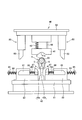
- FIG. 3 is a side view showing the knuckle bracket manufacturing apparatus according to the embodiment of the present invention, and shows a state where the upper frame is located at the top dead center.
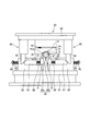
- FIG. 4 is a front view of the width forming machine in the state of FIG. 3.
- FIG. 4 is a front view of the width forming machine in the state of FIG. 3.
- FIG. 5 is a front view of the drilling machine in the state of FIG.
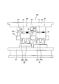
- FIG. 6 is a side view showing the knuckle bracket manufacturing apparatus according to the embodiment of the present invention, and shows a state where the upper frame is located between the top dead center and the bottom dead center.
- FIG. 7 is a front view of the width forming machine in the state of FIG.
- FIG. 8 is a front view of the punching machine in the state of FIG.
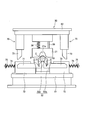
- FIG. 9 is a side view showing the knuckle bracket manufacturing apparatus according to the embodiment of the present invention, and shows a state where the upper frame is located at the bottom dead center.
- FIG. 10 is a front view of the width forming machine in the state of FIG.
- FIG. 11 is a front view of the punching machine in the state of FIG.
- FIG. 12 is a partially enlarged view of FIG.
- FIG. 13 is a partially enlarged view of FIG.
- FIG. 14 is a diagram illustrating a comparative example.
- the manufacturing apparatus 100 for the knuckle bracket 1 according to the embodiment of the present invention will be described.
- the knuckle bracket 1 is for attaching a shock absorber to a steering knuckle of a vehicle.
- the knuckle bracket 1 includes a bracket body 2 having a C-shaped cross section having an inner peripheral shape along the tube 10 of the shock absorber, and a pair of attachment portions that are formed to protrude from both ends of the bracket body 2 in parallel to each other and fastened to a steering knuckle 3 and 4 and a pair of ribs 5 and 6 as a refracting portion formed by being refracted inward from the end portions of the pair of attachment portions 3 and 4.
- the bracket body 2 is welded and fixed to the lower portion of the tube 10 while holding the tube 10 of the shock absorber.
- Each of the pair of attachment portions 3 and 4 is formed with two attachment holes 3a and 4a for fastening bolts.
- a fastening portion of the steering knuckle is inserted between the pair of mounting portions 3 and 4, and the pair of mounting portions 3 and 4 and the steering knuckle are fastened by bolts that pass through the mounting holes 3a and 4a and the fastening portion.
- the shock absorber is attached to the steering knuckle via the knuckle bracket 1.
- the pair of ribs 5 and 6 are for increasing the strength of the mounting portions 3 and 4.
- the knuckle bracket 1 is formed from a blank process for processing a metal plate material, through a press forming process, a rib bending forming process, a bending forming process, a width forming process, and a punching process shown in FIGS. 2A to 2E.
- the In blank processing the base material of the knuckle bracket 1 is punched out from a metal plate material.
- the press molding process the base material obtained by the blanking process is press-molded to form the part to be the bracket body 2 and the part to be the attachment portions 3 and 4.
- the rib bending process the ribs 5 and 6 are formed by bending.
- the bracket body 2 is formed by bending.
- the width forming step the width of the pair of attachment portions 3 and 4 is formed to a predetermined dimension.
- the mounting holes 3a and 4a are processed in the pair of mounting portions 3 and 4.
- the manufacturing apparatus 100 will be described with reference to FIGS.
- the manufacturing apparatus 100 is an apparatus that continuously performs a press molding process, a rib bending molding process, a bending molding process, a width molding process, and a punching process by a transfer press.
- the manufacturing apparatus 100 has a dedicated mold for performing each process, and the workpieces 9 are sequentially conveyed to the molds of each process and are automatically processed continuously.
- the manufacturing apparatus 100 includes a press machine that performs a press molding process, a rib bending machine that performs a rib bending process, a bending machine that performs a bending process, a width molding machine 30 that performs a width molding process, and a hole punching process. And a punching machine 40 for performing the process. 3, 6 and 9, only the width forming machine 30 and the punching machine 40 are shown, and the press working machine, the rib bending forming machine, and the bending forming machine are not shown.
- the manufacturing apparatus 100 includes an upper frame 62 that is provided with dedicated dies 31 and 41 for performing a width forming step and a hole making step, respectively, and configured to be movable up and down.
- a hydraulic cylinder or a servo motor is used as a drive source for moving the upper frame 62 up and down.
- a conveyance mechanism (not shown) conveys the workpiece 9 to the width forming machine 30 and the punching machine 40. By doing so, the workpiece 9 is automatically machined.
- the workpiece 9 is transported in a state where the upper gantry 62 is located at the top dead center, and each process is formed while the upper gantry 62 is lowered from the top dead center to the bottom dead center.
- 3 to 5 show the state where the upper frame 62 is located at the top dead center
- FIGS. 6 to 8 show the state where the upper frame 62 is located between the top dead center and the bottom dead center
- FIGS. The state which the mount frame 62 is located in a bottom dead center is shown.
- the width forming machine 30 includes a receiving die 32 provided on the lower pedestal 61 so as to be movable up and down, a core die 33 as a support shaft for supporting the work 9, and a pair of mounting portions 3, 4 provided on the upper pedestal 62. And a pressing mechanism 70 that presses the pair of attachment parts 3 and 4 against the receiving die 32.
- the receiving die 32 includes a base 32 a and a receiving portion 32 b that is located between the pair of mounting portions 3 and 4 and defines the width dimension of the pair of mounting portions 3 and 4.
- the base 32 a is supported by the lower base 61 via a guide pin 35 and a spring 36 slidable on the lower base 61.
- the core mold 33 is a cylindrical mold having an outer peripheral shape along the inner peripheral shape of the bracket body 2.
- the core mold 33 is formed by being coupled to the upper end of the receiving portion 32 b of the receiving die 32.
- the core mold 33 and the receiving die 32 are integrally formed.
- the core mold 33 is formed so as to extend to the drilling machine 40 in the next process, and is used in both the width forming process and the drilling process.
- the mold 31 is suspended from the upper frame 62 via a guide pin 39 and a spring 38 that are slidable on the upper frame 62.
- the mold 31 has a die carving 31 a that follows the outer peripheral shape of the bracket body 2.
- the lower frame 61 is provided with a pair of gas cylinders 37.
- a pin 37 a is provided at the rod tip of the gas cylinder 37. In the gas cylinder 37, the pin 37 a comes into contact with the core mold 33 before the mold 31 comes into contact with the workpiece 9 when the upper frame 62 descends from the top dead center to the bottom dead center. 33 is lowered. 4, 7, and 10, the gas cylinder 37 is not shown.
- the pressing mechanism 70 is provided on a slider 71 that is movably provided on both sides of the receiving die 32 and applies a pressing force to the pair of mounting portions 3, 4.
- a support base 72 provided to support the slider 71, and a wedge cam 73 provided on both sides of the mold 31 in the upper frame 62 and advancing the slider 71 toward the receiving portion 32b to generate a pressing force.
- An inclined surface corresponding to the inclined surface of the wedge cam 73 is formed on the back surface of the slider 71.
- a front end portion of a bolt 74 that is slidably inserted through the support base 72 is fastened.
- a return spring 75 is interposed between the head of the bolt 74 and the support base 72.
- the conveyance of the workpiece 9 from the bending machine to the width molding machine 30 as a pre-process is performed in a state where the upper frame 62 is located at the top dead center.
- the receiving die 32 is urged by the urging force of the spring 36, and the core die 33 is raised to the maximum height (the state shown in FIGS. 3 and 4).
- the work 9 is gripped and transported by the transport fingers provided in the transport mechanism, and is supported by the core mold 33. In this way, the work 9 is conveyed from the bending machine to the width molding machine 30.
- the pin 37a of the gas cylinder 37 contacts the core mold 33 before the wedge cam 73 is pressed against the slider 71, and the core mold 33 It is pushed by the gas cylinder 37 and descends.
- the receiving die 32 integrated with the core mold 33 is lowered while compressing the spring 36 and comes into contact with the lower mount 61 (the state shown in FIGS. 6 and 7).
- the slider 71 can move forward without interfering with the base 32 a of the receiving die 32.
- the core die 33 integral with the receiving die 32 is located at the minimum height.
- the wedge cam 73 is pressed against the slider 71 and the slider 71 advances.
- the slider 71 presses the pair of attachment portions 3 and 4 toward the receiving portion 32b.
- variety of a pair of attaching parts 3 and 4 is shape
- the ribs 5 and 6 do not interfere with the receiving portion 32b so as to follow the end surface of the receiving portion 32b, that is, the ribs 5 and 6 interfere with the receiving portion 32b and do not hinder width forming.
- the workpiece 9 is supported by the core mold 33. Specifically, when the work 9 is transported from the bending machine, which is the previous process, to the core mold 33, the relative position of the work 9 with respect to the receiving portion 32b is positioned.
- the workpiece 9 is positioned by, for example, controlling the amount of movement of the workpiece 9 with a servo motor that drives the conveyance fingers.
- the pressing of the core mold 33 by the gas cylinder 37 and the urging of the mold 31 by the spring 38 are released, so that the receiving die 32 is moved by the urging force of the spring 36.
- the core mold 33 is energized and is in a state of being raised to the maximum height (the state shown in FIG. 3).
- the punching machine 40 includes a receiving die 42 provided on the lower pedestal 61, a core mold 33 that is used in common with the width forming machine 30 and supports the work 9, and an attachment hole 3a, 4a provided on the upper pedestal 62.
- a mold 41 that supports the workpiece 9 with the core mold 33 during processing, a punch 43 that punches the mounting holes 3a and 4a into the pair of mounting portions 3 and 4, and a drive mechanism 80 that drives the punch 43.
- the receiving die 42 includes a base 42a and a receiving portion 42b sandwiched between the pair of mounting portions 3 and 4 when the mounting holes 3a and 4a are processed.
- the receiving portion 42b is formed with a through hole 42c (see FIGS. 12 and 13) into which the punch 43 enters when the mounting holes 3a and 4a are processed.
- the mold 41 is suspended from the upper frame 62 via a guide pin 44 and a spring 45 slidable on the upper frame 62.
- the mold 41 has a die carving 41 a that follows the outer peripheral shape of the bracket body 2.
- the drive mechanism 80 is provided on both sides of the receiving die 42 to support the punch 43 and is movable in the axial direction of the punch 43, a support base 82 provided on the lower frame 61 and supporting the slider 81, and an upper part A wedge cam 83 provided on both sides of the mold 41 in the gantry 62 and moving the slider 81 forward toward the receiving portion 42b.
- An inclined surface corresponding to the inclined surface of the wedge cam 83 is formed on the back surface of the slider 81.
- the punch 43 When the mounting portions 3 and 4 are punched by the punch 43, the punch 43 is pressed against the receiving portion 42b with a portion other than the punching portions 3 and 4 so as to prevent deformation of the mounting portions 3 and 4.
- a stripper 87 is provided. The punch 43 is inserted through the stripper 87, and a spring 88 is interposed between the stripper 87 and the slider 81.
- a front end portion of a bolt 84 that is slidably inserted through the support base 82 is fastened.
- a return spring 85 is interposed between the head of the bolt 84 and the support base 82.
- the conveyance of the work 9 from the width forming machine 30 to the punching machine 40, which is the previous process, is performed in a state where the upper frame 62 is located at the top dead center.
- the core mold 33 is located at the maximum height as described above (the state shown in FIG. 3).
- the width forming by the width forming machine 30 is completed, and the workpiece 9 supported by the core mold 33 is gripped by the transport fingers provided in the transport mechanism and slid along the core mold 33.
- the height of the core mold 33 is set so that the workpiece 9 does not interfere with the receiving portion 42b of the receiving die 42, that is, the sliding of the workpiece 9 is not inhibited by the receiving portion 42b.
- the workpiece 9 is supported by the core mold 33 so that the ribs 5 and 6 do not interfere with the receiving portion 42b when the core mold 33 is lowered. Specifically, when the work 9 is slid and conveyed along the core mold 33, the relative position of the work 9 with respect to the receiving portion 42b is positioned.
- the workpiece 9 is positioned by, for example, controlling the amount of movement of the workpiece 9 with a servo motor that drives the conveyance fingers.
- the wedge cam 83 is pressed against the slider 81 and the slider 81 advances.
- the end surfaces of the stripper 87 and the punch 43 abut against the outer surfaces of the attachment portions 3 and 4 of the workpiece 9.
- the punch 43 bites into the attachment portions 3 and 4
- the stripper 87 is pressed against the attachment portions 3 and 4 by the biasing force of the spring 88 compressed between the stripper 87 and the slider 81.
- the tip of the punch 43 reaches the through hole 42c of the receiving portion 42b, and the mounting portions 3 and 4 are punched out (state shown in FIGS. 11 and 13).
- the mounting holes 3a and 4a are processed continuously with the width forming of the pair of mounting portions 3 and 4. There is no need to use a dedicated press. Therefore, the manufacturing cost of the knuckle bracket 1 can be reduced.
- the work 9 is transported from the width forming machine 30 to the punching machine 40 after the core mold 33 is lifted, and then the work 9 is moved along the core mold 33 to the position above the receiving die 42. This is done by lowering the mold 33 until it contacts the upper surface of the receiving portion 42b of the die 42.
- the workpiece 9 is set on the receiving portion 42b from above the receiving portion 42b.
- the workpiece 9 is not set on the receiving portion 42b from above the receiving portion 42b, but is set on the receiving portion 42b simply by sliding the workpiece 9 along the core mold 33. In this case, it is necessary to make the receiving portion 42b in the shape shown by the slanted line in FIG.
- the work 9 is set on the receiving portion 42b from above the receiving portion 42b, it is not necessary to provide the neck portion 95 on the receiving portion 42b as shown in FIGS. 12 and 13, and the receiving portion 42b. Can be ensured.
- the workpiece 9 is set on the receiving portion 42b from above the receiving portion 42b, so that the width forming step and the punching step can be continuously performed.
- the width of the pair of attachment portions 3, 4 may be formed to a predetermined dimension by bending with the mold 31.
Abstract
A device for manufacturing a knuckle bracket having: a bracket body having an inner peripheral shape that follows a shock absorber tube; and a pair of attachment parts formed so as to protrude in a parallel manner from both ends of the bracket body, wherein: the device is provided with a width shaping apparatus for shaping the widths of the pair of attachment parts while a workpiece is supported on a supporting shaft, and a hole forming apparatus for machining attachment holes in the pair of attachment parts while the workpiece is supported on the support shaft and the pair of attachment parts are facing both side surfaces of a die; and conveying of the workpiece (9) from the width shaping apparatus to the hole forming apparatus involves raising the support shaft, moving the workpiece along the raised support shaft to a position above the die, and lowering the workpiece until the support shaft comes into contact with the upper surface of the die.
Description
本発明は、緩衝器を車両に取り付けるためのナックルブラケットの製造装置及び製造方法に関するものである。
The present invention relates to a manufacturing apparatus and manufacturing method for a knuckle bracket for attaching a shock absorber to a vehicle.
従来のナックルブラケットとして、JP1997-89036Aには、軸方向に延びる湾曲部と湾曲部の周方向両端に形成された直線部とを備え、湾曲部の内側に液圧緩衝器の下端部が挿入して固定されるものが開示されている。一対の直線部には、車両への取付ボルトが挿通する取付孔が形成される。
As a conventional knuckle bracket, JP1997-89036A includes a curved portion extending in the axial direction and straight portions formed at both ends in the circumferential direction of the curved portion, and a lower end portion of the hydraulic shock absorber is inserted inside the curved portion. Are fixed. The pair of straight portions are formed with mounting holes through which mounting bolts to the vehicle are inserted.
一般的に、ナックルブラケットの製造は、板材をブランク加工してから曲げ加工することによって湾曲部と直線部を成形し、最後に一対の直線部に穴開け加工することによって取付孔を形成する。曲げ加工の前に穴開け加工する方法もあるが、この方法では一対の直線部に形成される取付孔の同軸度を確保するのが困難である。したがって、取付孔の同軸度を確保するためには、製造工程の最後に穴開け加工するのが一般的である。
Generally, in the manufacture of a knuckle bracket, a bent portion and a straight portion are formed by blanking and then bending a plate material, and finally a mounting hole is formed by drilling a pair of straight portions. Although there is a method of drilling before bending, it is difficult to ensure the coaxiality of the mounting holes formed in the pair of straight portions. Therefore, in order to ensure the coaxiality of the mounting holes, it is common to perform drilling at the end of the manufacturing process.
穴開け加工はブランク加工から曲げ加工までを行うラインとは別の専用のプレス機を用いて行う必要があるため、穴開け加工費用が追加で発生してしまい、ナックルブラケットの製造コストが増加してしまう。
Since drilling needs to be performed using a dedicated press machine separate from the blanking to bending process, additional drilling costs are incurred, increasing the knuckle bracket manufacturing cost. End up.
本発明は、ナックルブラケットの製造コストを低減することを目的とする。
The present invention aims to reduce the manufacturing cost of the knuckle bracket.
本発明のある態様によれば、緩衝器のチューブに沿った内周形状を有し前記チューブに固定されるブラケット本体と、前記ブラケット本体の両端から互いに平行に突出して形成されステアリングナックルに締結される一対の取付部と、を備えるナックルブラケットの製造装置であって、前記ブラケット本体の内周形状に沿った外周形状を有し、ワークを支持する支持軸と、前記支持軸にてワークを支持した状態で、前記一対の取付部の幅を所定寸法に成形する幅成形機と、前記支持軸にてワークを支持すると共にダイの両側面に前記一対の取付部が対向した状態で、前記一対の取付部に取付穴を加工する穴開け機と、を備え、前記幅成形機から前記穴開け機へのワークの搬送は、前記支持軸を上昇させた後、前記ワークを前記支持軸に沿って前記ダイの上方まで移動させ、前記支持軸を前記ダイ上面に当接するまで下降させることによって行う。
According to an aspect of the present invention, a bracket body having an inner peripheral shape along a tube of a shock absorber and fixed to the tube, and formed to protrude from both ends of the bracket body in parallel to each other, are fastened to a steering knuckle. A knuckle bracket manufacturing apparatus comprising a pair of mounting portions, having an outer peripheral shape along an inner peripheral shape of the bracket body, and supporting the workpiece by the support shaft and the support shaft. In a state where the pair of attachment portions are formed to have a predetermined width, the pair of attachment portions are supported by the support shaft and the pair of attachment portions are opposed to both side surfaces of the die. A hole punching machine for forming a mounting hole in the mounting portion, and the workpiece is transferred from the width forming machine to the hole punching machine after the support shaft is lifted, and then the workpiece is moved along the support shaft. It is moved to above the die, carried out by lowering until it abuts the supporting shaft to the die upper surface.
本発明の別の態様によれば、緩衝器のチューブに沿った内周形状を有し前記チューブに固定されるブラケット本体と、前記ブラケット本体の両端から互いに平行に突出して形成されステアリングナックルに締結される一対の取付部と、を備えるナックルブラケットを製造する製造方法であって、前記一対の取付部の幅を所定寸法に成形する幅成形工程と、ダイの両側面に前記一対の取付部が対向した状態で、前記一対の取付部に取付穴を加工する穴開け工程と、を備え、前記幅成形工程及び前記穴開け工程は、前記ブラケット本体の内周形状に沿った外周形状を有する支持軸にてワークを支持した状態で行われ、前記幅成形工程から前記穴開け工程へのワークの搬送は、前記支持軸を上昇させた後、前記ワークを前記支持軸に沿って前記ダイの上方まで移動させ、前記支持軸を前記ダイ上面に当接するまで下降させることによって行う。
According to another aspect of the present invention, a bracket body having an inner peripheral shape along the tube of the shock absorber and fixed to the tube, and formed to protrude parallel to each other from both ends of the bracket body, are fastened to a steering knuckle. A pair of mounting portions, and a manufacturing method for manufacturing a knuckle bracket, wherein the pair of mounting portions are formed on both side surfaces of a die, and a width forming step of forming the width of the pair of mounting portions into a predetermined dimension. A hole forming step for forming attachment holes in the pair of attachment portions in a state of being opposed to each other, wherein the width forming step and the hole forming step have an outer peripheral shape along an inner peripheral shape of the bracket body. The workpiece is transported from the width forming step to the drilling step by lifting the support shaft and then moving the workpiece along the support shaft. Move up upward, carried out by lowering until it abuts the supporting shaft to the die upper surface.
以下、図面を参照して、本発明の実施形態について説明する。
Hereinafter, embodiments of the present invention will be described with reference to the drawings.
本発明の実施形態に係るナックルブラケット1の製造装置100について説明する。
The manufacturing apparatus 100 for the knuckle bracket 1 according to the embodiment of the present invention will be described.
まず、図1を参照して、ナックルブラケット1について説明する。ナックルブラケット1は、緩衝器を車両のステアリングナックルに取り付けるためのものである。
First, the knuckle bracket 1 will be described with reference to FIG. The knuckle bracket 1 is for attaching a shock absorber to a steering knuckle of a vehicle.
ナックルブラケット1は、緩衝器のチューブ10に沿った内周形状を有する断面C型のブラケット本体2と、ブラケット本体2の両端から互いに平行に突出して形成されステアリングナックルに締結される一対の取付部3,4と、一対の取付部3,4の端部から内側に屈折して形成された屈折部としての一対のリブ5,6と、を備える。
The knuckle bracket 1 includes a bracket body 2 having a C-shaped cross section having an inner peripheral shape along the tube 10 of the shock absorber, and a pair of attachment portions that are formed to protrude from both ends of the bracket body 2 in parallel to each other and fastened to a steering knuckle 3 and 4 and a pair of ribs 5 and 6 as a refracting portion formed by being refracted inward from the end portions of the pair of attachment portions 3 and 4.
ブラケット本体2は、緩衝器のチューブ10を抱えた状態でチューブ10の下部に溶接固定される。
The bracket body 2 is welded and fixed to the lower portion of the tube 10 while holding the tube 10 of the shock absorber.
一対の取付部3,4のそれぞれには、ボルト締結用の取付穴3a,4aが2つずつ形成される。一対の取付部3,4の間には、ステアリングナックルの締結部が挿入され、一対の取付部3,4とステアリングナックルとは、取付穴3a,4aと締結部とを挿通するボルトによって締結される。このように、緩衝器は、ナックルブラケット1を介してステアリングナックルに取り付けられる。
Each of the pair of attachment portions 3 and 4 is formed with two attachment holes 3a and 4a for fastening bolts. A fastening portion of the steering knuckle is inserted between the pair of mounting portions 3 and 4, and the pair of mounting portions 3 and 4 and the steering knuckle are fastened by bolts that pass through the mounting holes 3a and 4a and the fastening portion. The Thus, the shock absorber is attached to the steering knuckle via the knuckle bracket 1.
一対のリブ5,6は、取付部3,4の強度を高くするためのものである。
The pair of ribs 5 and 6 are for increasing the strength of the mounting portions 3 and 4.
ナックルブラケット1は、金属製の板材を加工するブランク加工から、図2A~2Eに示すプレス成形工程、リブ曲げ成形工程、曲げ成形工程、幅成形工程、及び穴開け工程の各工程を経て成形される。ブランク加工では、金属製の板材からナックルブラケット1の素地を打ち抜く。プレス成形工程では、ブランク加工によって得られた素地をプレス成形してブラケット本体2となる部位と取付部3,4となる部位とを成形する。リブ曲げ成形工程では、曲げ加工によってリブ5,6を成形する。曲げ成形工程では、曲げ加工によってブラケット本体2を成形する。幅成形工程では、一対の取付部3,4の幅を所定寸法に成形する。穴開け工程では、一対の取付部3,4に取付穴3a,4aを加工する。
The knuckle bracket 1 is formed from a blank process for processing a metal plate material, through a press forming process, a rib bending forming process, a bending forming process, a width forming process, and a punching process shown in FIGS. 2A to 2E. The In blank processing, the base material of the knuckle bracket 1 is punched out from a metal plate material. In the press molding process, the base material obtained by the blanking process is press-molded to form the part to be the bracket body 2 and the part to be the attachment portions 3 and 4. In the rib bending process, the ribs 5 and 6 are formed by bending. In the bending process, the bracket body 2 is formed by bending. In the width forming step, the width of the pair of attachment portions 3 and 4 is formed to a predetermined dimension. In the drilling step, the mounting holes 3a and 4a are processed in the pair of mounting portions 3 and 4.
図3~14を参照して、製造装置100について説明する。
The manufacturing apparatus 100 will be described with reference to FIGS.
製造装置100は、プレス成形工程、リブ曲げ成形工程、曲げ成形工程、幅成形工程、及び穴開け工程をトランスファープレスによって連続して行う装置である。製造装置100は各工程を行う専用の金型を有し、各工程の金型にワーク9を順番に搬送して連続して自動加工する。
The manufacturing apparatus 100 is an apparatus that continuously performs a press molding process, a rib bending molding process, a bending molding process, a width molding process, and a punching process by a transfer press. The manufacturing apparatus 100 has a dedicated mold for performing each process, and the workpieces 9 are sequentially conveyed to the molds of each process and are automatically processed continuously.
製造装置100は、プレス成形工程を行うプレス加工機と、リブ曲げ成形工程を行うリブ曲げ成形機と、曲げ成形工程を行う曲げ成形機と、幅成形工程を行う幅成形機30と、穴開け工程を行う穴開け機40と、を備える。図3,6,及び9では、幅成形機30及び穴開け機40のみを示し、プレス加工機、リブ曲げ成形機、及び曲げ成形機の図示は省略する。
The manufacturing apparatus 100 includes a press machine that performs a press molding process, a rib bending machine that performs a rib bending process, a bending machine that performs a bending process, a width molding machine 30 that performs a width molding process, and a hole punching process. And a punching machine 40 for performing the process. 3, 6 and 9, only the width forming machine 30 and the punching machine 40 are shown, and the press working machine, the rib bending forming machine, and the bending forming machine are not shown.
製造装置100は、幅成形工程及び穴開け工程をそれぞれ行う専用の金型31,41が設けられて上下動可能に構成された上部架台62を備える。上部架台62を上下動させる駆動源としては、例えば、油圧シリンダやサーボモータが用いられる。
The manufacturing apparatus 100 includes an upper frame 62 that is provided with dedicated dies 31 and 41 for performing a width forming step and a hole making step, respectively, and configured to be movable up and down. For example, a hydraulic cylinder or a servo motor is used as a drive source for moving the upper frame 62 up and down.
上部架台62が図3に示す上死点と図9に示す下死点の間で往復動するのに同期して、図示しない搬送機構がワーク9を幅成形機30及び穴開け機40に搬送することによって、ワーク9の自動加工が行われる。上部架台62が上死点に位置した状態で、ワーク9の搬送が行われ、上部架台62が上死点から下死点に下降する過程で各工程の成形が行われる。図3~5は上部架台62が上死点に位置する状態を示し、図6~8は上部架台62が上死点と下死点の間に位置する状態を示し、図9~11は上部架台62が下死点に位置する状態を示す。
In synchronization with the upper frame 62 reciprocating between the top dead center shown in FIG. 3 and the bottom dead center shown in FIG. 9, a conveyance mechanism (not shown) conveys the workpiece 9 to the width forming machine 30 and the punching machine 40. By doing so, the workpiece 9 is automatically machined. The workpiece 9 is transported in a state where the upper gantry 62 is located at the top dead center, and each process is formed while the upper gantry 62 is lowered from the top dead center to the bottom dead center. 3 to 5 show the state where the upper frame 62 is located at the top dead center, FIGS. 6 to 8 show the state where the upper frame 62 is located between the top dead center and the bottom dead center, and FIGS. The state which the mount frame 62 is located in a bottom dead center is shown.
まず、図3,4,6,7,9,及び10を参照して、幅成形機30について説明する。
First, the width forming machine 30 will be described with reference to FIGS. 3, 4, 6, 7, 9, and 10.
幅成形機30は、下部架台61に上下動可能に設けられた受けダイ32と、ワーク9を支持する支持軸としての中子型33と、上部架台62に設けられ一対の取付部3,4の幅成形時に中子型33との間でワーク9を支持する金型31と、受けダイ32に対して一対の取付部3,4を押圧する押圧機構70と、を備える。
The width forming machine 30 includes a receiving die 32 provided on the lower pedestal 61 so as to be movable up and down, a core die 33 as a support shaft for supporting the work 9, and a pair of mounting portions 3, 4 provided on the upper pedestal 62. And a pressing mechanism 70 that presses the pair of attachment parts 3 and 4 against the receiving die 32.
受けダイ32は、基台32aと、一対の取付部3,4の間に位置し一対の取付部3,4の幅寸法を規定するための受部32bと、を有する。基台32aは、下部架台61に摺動自在なガイドピン35とスプリング36とを介して下部架台61に支持される。
The receiving die 32 includes a base 32 a and a receiving portion 32 b that is located between the pair of mounting portions 3 and 4 and defines the width dimension of the pair of mounting portions 3 and 4. The base 32 a is supported by the lower base 61 via a guide pin 35 and a spring 36 slidable on the lower base 61.
中子型33は、ブラケット本体2の内周形状に沿った外周形状を有する円柱状の型である。中子型33は、受けダイ32の受部32bの上端に結合して形成される。このように、中子型33と受けダイ32は一体に形成される。中子型33は、次工程の穴開け機40まで延在して形成され、幅成形工程及び穴開け工程の双方で共通に使用される。
The core mold 33 is a cylindrical mold having an outer peripheral shape along the inner peripheral shape of the bracket body 2. The core mold 33 is formed by being coupled to the upper end of the receiving portion 32 b of the receiving die 32. Thus, the core mold 33 and the receiving die 32 are integrally formed. The core mold 33 is formed so as to extend to the drilling machine 40 in the next process, and is used in both the width forming process and the drilling process.
金型31は、上部架台62に摺動自在なガイドピン39とスプリング38とを介して上部架台62に吊り下げられている。金型31は、ブラケット本体2の外周形状に沿った型彫り31aを有する。
The mold 31 is suspended from the upper frame 62 via a guide pin 39 and a spring 38 that are slidable on the upper frame 62. The mold 31 has a die carving 31 a that follows the outer peripheral shape of the bracket body 2.
下部架台61には、一対のガスシリンダ37が設けられる。ガスシリンダ37のロッド先端にはピン37aが設けられる。ガスシリンダ37は、上部架台62が上死点から下死点に下降する際に、金型31がワーク9に当接するのに先立って、ピン37aが中子型33に当接して中子型33を下降させる。なお、図4,7,及び10ではガスシリンダ37の図示を省略している。
The lower frame 61 is provided with a pair of gas cylinders 37. A pin 37 a is provided at the rod tip of the gas cylinder 37. In the gas cylinder 37, the pin 37 a comes into contact with the core mold 33 before the mold 31 comes into contact with the workpiece 9 when the upper frame 62 descends from the top dead center to the bottom dead center. 33 is lowered. 4, 7, and 10, the gas cylinder 37 is not shown.
押圧機構70は、図4,7,及び10に示すように、受けダイ32の両側方に移動自在に設けられ一対の取付部3,4に押圧力を付与するスライダ71と、下部架台61に設けられスライダ71を支持する支持台72と、上部架台62における金型31の両側方に設けられスライダ71を受部32bに向けて前進させて押圧力を発生させる楔カム73と、を備える。
As shown in FIGS. 4, 7, and 10, the pressing mechanism 70 is provided on a slider 71 that is movably provided on both sides of the receiving die 32 and applies a pressing force to the pair of mounting portions 3, 4. A support base 72 provided to support the slider 71, and a wedge cam 73 provided on both sides of the mold 31 in the upper frame 62 and advancing the slider 71 toward the receiving portion 32b to generate a pressing force.
スライダ71の背面には、楔カム73の傾斜面に対応する傾斜面が形成される。上部架台62が上死点から下死点に下降する際には、楔カム73の傾斜面がスライダ71背面の傾斜面に押し付けられることによって、スライダ71が前進する。
An inclined surface corresponding to the inclined surface of the wedge cam 73 is formed on the back surface of the slider 71. When the upper frame 62 is lowered from the top dead center to the bottom dead center, the inclined surface of the wedge cam 73 is pressed against the inclined surface on the back surface of the slider 71, so that the slider 71 moves forward.
スライダ71の後端部には、支持台72を摺動自在に挿通するボルト74の先端部が締結される。ボルト74の頭部と支持台72との間には、戻しスプリング75が介装される。楔カム73がスライダ71に押し付けられスライダ71が前進すると、戻しスプリング75はボルト74の頭部と支持台72との間で圧縮される。スライダ71に対する楔カム73の押し付けが解除されると、戻しスプリング75の付勢力によってスライダ71は後退して元の位置に復帰する。
At the rear end portion of the slider 71, a front end portion of a bolt 74 that is slidably inserted through the support base 72 is fastened. A return spring 75 is interposed between the head of the bolt 74 and the support base 72. When the wedge cam 73 is pressed against the slider 71 and the slider 71 moves forward, the return spring 75 is compressed between the head of the bolt 74 and the support base 72. When the pressing of the wedge cam 73 against the slider 71 is released, the slider 71 moves backward by the urging force of the return spring 75 and returns to the original position.
幅成形機30の動作について説明する。
The operation of the width forming machine 30 will be described.
前工程である曲げ成形機から幅成形機30へのワーク9の搬送は、上部架台62が上死点に位置した状態で行われる。上部架台62が上死点に位置した状態では、スプリング36の付勢力によって受けダイ32が付勢され、中子型33は最大高さまで上昇した状態となる(図3及び4に示す状態)。この状態で、ワーク9を搬送機構に設けられた搬送フィンガーにて把持して搬送し、中子型33に支持させる。このようにして、曲げ成形機から幅成形機30へのワーク9の搬送が行われる。
The conveyance of the workpiece 9 from the bending machine to the width molding machine 30 as a pre-process is performed in a state where the upper frame 62 is located at the top dead center. In a state where the upper frame 62 is located at the top dead center, the receiving die 32 is urged by the urging force of the spring 36, and the core die 33 is raised to the maximum height (the state shown in FIGS. 3 and 4). In this state, the work 9 is gripped and transported by the transport fingers provided in the transport mechanism, and is supported by the core mold 33. In this way, the work 9 is conveyed from the bending machine to the width molding machine 30.
上部架台62が上死点から下死点に下降する際には、楔カム73がスライダ71に押し付けられる前に、ガスシリンダ37のピン37aが中子型33に当接し、中子型33はガスシリンダ37によって押し付けられて下降する。これにより、中子型33と一体の受けダイ32は、スプリング36を圧縮しながら下降して下部架台61に当接する(図6及び7に示す状態)。これにより、スライダ71が受けダイ32の基台32aと干渉せずに前進可能な状態となる。また、受けダイ32と一体の中子型33は最小高さに位置する。
When the upper frame 62 descends from the top dead center to the bottom dead center, the pin 37a of the gas cylinder 37 contacts the core mold 33 before the wedge cam 73 is pressed against the slider 71, and the core mold 33 It is pushed by the gas cylinder 37 and descends. Thereby, the receiving die 32 integrated with the core mold 33 is lowered while compressing the spring 36 and comes into contact with the lower mount 61 (the state shown in FIGS. 6 and 7). As a result, the slider 71 can move forward without interfering with the base 32 a of the receiving die 32. Further, the core die 33 integral with the receiving die 32 is located at the minimum height.
図7に示す状態から上部架台62がさらに下降すると、ガスシリンダ37が収縮し始め、金型31の型彫り31aがワーク9のブラケット本体2の外周に当接する。これにより、ワーク9は中子型33と金型31の間で支持された状態となる。
7 is further lowered from the state shown in FIG. 7, the gas cylinder 37 starts to contract, and the die 31a of the die 31 comes into contact with the outer periphery of the bracket body 2 of the workpiece 9. As a result, the workpiece 9 is supported between the core mold 33 and the mold 31.
上部架台62がガスシリンダ37とスプリング38を圧縮しながらさらに下降すると、楔カム73がスライダ71に押し付けられスライダ71が先進する。スライダ71は、受部32bに向けて一対の取付部3,4を押し付ける。これにより、一対の取付部3,4の幅は所定寸法に成形される(図9及び10に示す状態)。一対の取付部3,4の幅は受部32bの幅と略等しくなるため、受部32bの幅を調整することによって一対の取付部3,4の幅を所望の寸法に成形することが可能となる。
When the upper frame 62 further descends while compressing the gas cylinder 37 and the spring 38, the wedge cam 73 is pressed against the slider 71 and the slider 71 advances. The slider 71 presses the pair of attachment portions 3 and 4 toward the receiving portion 32b. Thereby, the width | variety of a pair of attaching parts 3 and 4 is shape | molded by the predetermined dimension (state shown to FIG. 9 and 10). Since the width of the pair of mounting portions 3 and 4 is substantially equal to the width of the receiving portion 32b, the width of the pair of mounting portions 3 and 4 can be formed to a desired dimension by adjusting the width of the receiving portion 32b. It becomes.
幅成形の際に、リブ5,6が受部32bと干渉せず受部32bの端面に沿うように、つまり、リブ5,6が受部32bと干渉して幅成形を阻害しないように、ワーク9は中子型33に支持されている。具体的には、前工程である曲げ成形機から中子型33へワーク9が搬送される際に、受部32bに対するワーク9の相対位置が位置決めされる。ワーク9の位置決めは、例えば、搬送フィンガーを駆動するサーボモータにてワーク9の移動量を制御することによって行われる。
At the time of width forming, the ribs 5 and 6 do not interfere with the receiving portion 32b so as to follow the end surface of the receiving portion 32b, that is, the ribs 5 and 6 interfere with the receiving portion 32b and do not hinder width forming. The workpiece 9 is supported by the core mold 33. Specifically, when the work 9 is transported from the bending machine, which is the previous process, to the core mold 33, the relative position of the work 9 with respect to the receiving portion 32b is positioned. The workpiece 9 is positioned by, for example, controlling the amount of movement of the workpiece 9 with a servo motor that drives the conveyance fingers.
上部架台62が下死点から上死点に上昇する際には、スライダ71に対する楔カム73の押し付けが解除されるため、戻しスプリング75の付勢力によってスライダ71は元の位置に復帰する。
When the upper frame 62 rises from the bottom dead center to the top dead center, the pressing of the wedge cam 73 against the slider 71 is released, so that the slider 71 returns to the original position by the urging force of the return spring 75.
上部架台62が上死点に到達した状態では、ガスシリンダ37による中子型33の押し付け、及びスプリング38による金型31の付勢が解除されるため、スプリング36の付勢力によって受けダイ32が付勢され、中子型33は最大高さまで上昇した状態となる(図3に示す状態)。
When the upper frame 62 reaches the top dead center, the pressing of the core mold 33 by the gas cylinder 37 and the urging of the mold 31 by the spring 38 are released, so that the receiving die 32 is moved by the urging force of the spring 36. The core mold 33 is energized and is in a state of being raised to the maximum height (the state shown in FIG. 3).
次に、図3,5,6,8,9,及び11~13を参照して、穴開け機40について説明する。
Next, with reference to FIGS. 3, 5, 6, 8, 9, and 11 to 13, the punching machine 40 will be described.
穴開け機40は、下部架台61に設けられた受けダイ42と、幅成形機30と共通で用いられワーク9を支持する中子型33と、上部架台62に設けられ取付穴3a,4aの加工時に中子型33との間でワーク9を支持する金型41と、一対の取付部3,4に取付穴3a,4aを打ち抜くパンチ43と、パンチ43を駆動する駆動機構80と、を備える。
The punching machine 40 includes a receiving die 42 provided on the lower pedestal 61, a core mold 33 that is used in common with the width forming machine 30 and supports the work 9, and an attachment hole 3a, 4a provided on the upper pedestal 62. A mold 41 that supports the workpiece 9 with the core mold 33 during processing, a punch 43 that punches the mounting holes 3a and 4a into the pair of mounting portions 3 and 4, and a drive mechanism 80 that drives the punch 43. Prepare.
受けダイ42は、基台42aと、取付穴3a,4aの加工時に一対の取付部3,4にて挟まれる受部42bと、を有する。受部42bには、取付穴3a,4aの加工時に、パンチ43が進入する貫通孔42c(図12及び13参照)が形成される。
The receiving die 42 includes a base 42a and a receiving portion 42b sandwiched between the pair of mounting portions 3 and 4 when the mounting holes 3a and 4a are processed. The receiving portion 42b is formed with a through hole 42c (see FIGS. 12 and 13) into which the punch 43 enters when the mounting holes 3a and 4a are processed.
金型41は、上部架台62に摺動自在なガイドピン44とスプリング45とを介して上部架台62に吊り下げられている。金型41は、ブラケット本体2の外周形状に沿った型彫り41aを有する。
The mold 41 is suspended from the upper frame 62 via a guide pin 44 and a spring 45 slidable on the upper frame 62. The mold 41 has a die carving 41 a that follows the outer peripheral shape of the bracket body 2.
駆動機構80は、受けダイ42の両側方に設けられパンチ43を支持すると共にパンチ43の軸方向に移動自在なスライダ81と、下部架台61に設けられスライダ81を支持する支持台82と、上部架台62における金型41の両側方に設けられスライダ81を受部42bに向けて前進させる楔カム83と、を備える。
The drive mechanism 80 is provided on both sides of the receiving die 42 to support the punch 43 and is movable in the axial direction of the punch 43, a support base 82 provided on the lower frame 61 and supporting the slider 81, and an upper part A wedge cam 83 provided on both sides of the mold 41 in the gantry 62 and moving the slider 81 forward toward the receiving portion 42b.
スライダ81の背面には、楔カム83の傾斜面に対応する傾斜面が形成される。上部架台62が上死点から下死点に下降する際には、楔カム83の傾斜面がスライダ81背面の傾斜面に押し付けられることによって、スライダ81が前進する。
An inclined surface corresponding to the inclined surface of the wedge cam 83 is formed on the back surface of the slider 81. When the upper frame 62 is lowered from the top dead center to the bottom dead center, the inclined surface of the wedge cam 83 is pressed against the inclined surface of the back surface of the slider 81, so that the slider 81 moves forward.
パンチ43には、取付部3,4がパンチ43にて打ち抜かれる際に、取付部3,4における打ち抜かれる以外の部分を受部42bに対して押し付け、取付部3,4の変形を防止するストリッパ87が設けられる。パンチ43はストリッパ87を挿通し、ストリッパ87とスライダ81の間にはスプリング88が介装される。
When the mounting portions 3 and 4 are punched by the punch 43, the punch 43 is pressed against the receiving portion 42b with a portion other than the punching portions 3 and 4 so as to prevent deformation of the mounting portions 3 and 4. A stripper 87 is provided. The punch 43 is inserted through the stripper 87, and a spring 88 is interposed between the stripper 87 and the slider 81.
スライダ81の後端部には、支持台82を摺動自在に挿通するボルト84の先端部が締結される。ボルト84の頭部と支持台82との間には、戻しスプリング85が介装される。楔カム83がスライダ81に押し付けられスライダ81が前進すると、戻しスプリング85はボルト84の頭部と支持台82との間で圧縮される。スライダ81に対する楔カム83の押し付けが解除されると、戻しスプリング85の付勢力によってスライダ81は後退して元の位置に復帰する。
At the rear end portion of the slider 81, a front end portion of a bolt 84 that is slidably inserted through the support base 82 is fastened. A return spring 85 is interposed between the head of the bolt 84 and the support base 82. When the wedge cam 83 is pressed against the slider 81 and the slider 81 moves forward, the return spring 85 is compressed between the head of the bolt 84 and the support 82. When the pressing of the wedge cam 83 against the slider 81 is released, the slider 81 moves backward by the urging force of the return spring 85 and returns to the original position.
穴開け機40の動作について説明する。
The operation of the punching machine 40 will be described.
前工程である幅成形機30から穴開け機40へのワーク9の搬送は、上部架台62が上死点に位置した状態で行われる。上部架台62が上死点に位置した状態では、上述のように、中子型33は最大高さに位置する(図3に示す状態)。この状態で、幅成形機30による幅成形が完了して中子型33に支持されたワーク9を、搬送機構に設けられた搬送フィンガーにて把持し、中子型33に沿ってスライドさせて受けダイ42の上方まで移動させる。ワーク9のスライドの際に、ワーク9が受けダイ42の受部42bに干渉しないように、つまりワーク9のスライドが受部42bにて阻害されないように、中子型33の高さが設定される。
The conveyance of the work 9 from the width forming machine 30 to the punching machine 40, which is the previous process, is performed in a state where the upper frame 62 is located at the top dead center. In the state where the upper mount 62 is located at the top dead center, the core mold 33 is located at the maximum height as described above (the state shown in FIG. 3). In this state, the width forming by the width forming machine 30 is completed, and the workpiece 9 supported by the core mold 33 is gripped by the transport fingers provided in the transport mechanism and slid along the core mold 33. Move to above the receiving die 42. When the workpiece 9 slides, the height of the core mold 33 is set so that the workpiece 9 does not interfere with the receiving portion 42b of the receiving die 42, that is, the sliding of the workpiece 9 is not inhibited by the receiving portion 42b. The
上部架台62が上死点から下死点に下降する際には、楔カム83がスライダ81に押し付けられる前に、ガスシリンダ37の作用によって、中子型33は受部42bの上面に当接するまで下降する(図6及び8に示す状態)。この状態では、一対の取付部3,4が受部42bの両側面を挟み、かつリブ5,6が受部42bと干渉せず受部42bの端面に沿った状態となる。このように、中子型33の下降は、リブ5,6が受部42bと干渉しないように行われる。つまり、ワーク9は、中子型33の下降の際に、リブ5,6が受部42bと干渉しないように中子型33に支持されている。具体的には、ワーク9が中子型33に沿ってスライド搬送される際に、受部42bに対するワーク9の相対位置が位置決めされる。ワーク9の位置決めは、例えば、搬送フィンガーを駆動するサーボモータにてワーク9の移動量を制御することによって行われる。
When the upper frame 62 descends from the top dead center to the bottom dead center, the core mold 33 abuts on the upper surface of the receiving portion 42b by the action of the gas cylinder 37 before the wedge cam 83 is pressed against the slider 81. (The state shown in FIGS. 6 and 8). In this state, the pair of mounting portions 3 and 4 sandwich both side surfaces of the receiving portion 42b, and the ribs 5 and 6 do not interfere with the receiving portion 42b and are along the end surface of the receiving portion 42b. In this way, the core mold 33 is lowered so that the ribs 5 and 6 do not interfere with the receiving portion 42b. That is, the workpiece 9 is supported by the core mold 33 so that the ribs 5 and 6 do not interfere with the receiving portion 42b when the core mold 33 is lowered. Specifically, when the work 9 is slid and conveyed along the core mold 33, the relative position of the work 9 with respect to the receiving portion 42b is positioned. The workpiece 9 is positioned by, for example, controlling the amount of movement of the workpiece 9 with a servo motor that drives the conveyance fingers.
図8に示す状態から上部架台62がさらに下降すると、ガスシリンダ37が収縮し始め、金型41の型彫り41aがワーク9のブラケット本体2の外周に当接する。これにより、ワーク9は中子型33と金型41の間で支持された状態となる。
When the upper mount 62 further descends from the state shown in FIG. 8, the gas cylinder 37 starts to contract, and the mold 41a of the mold 41 comes into contact with the outer periphery of the bracket body 2 of the workpiece 9. As a result, the workpiece 9 is supported between the core mold 33 and the mold 41.
上部架台62がガスシリンダ37とスプリング45を圧縮しながらさらに下降すると、楔カム83がスライダ81に押し付けられスライダ81が先進する。スライダ81の前進によって、ストリッパ87とパンチ43との先端面がワーク9の取付部3,4の外側面に当接する。さらにスライダ81が前進すれば、パンチ43は取付部3,4に食い込むと共に、ストリッパ87はストリッパ87とスライダ81の間で圧縮されたスプリング88の付勢力によって取付部3,4に押し付けられる。スライダ81の前進に伴って、パンチ43の先端が受部42bの貫通孔42cに到達し、取付部3,4が打ち抜かれる(図11及び13に示す状態)。
When the upper frame 62 further descends while compressing the gas cylinder 37 and the spring 45, the wedge cam 83 is pressed against the slider 81 and the slider 81 advances. As the slider 81 advances, the end surfaces of the stripper 87 and the punch 43 abut against the outer surfaces of the attachment portions 3 and 4 of the workpiece 9. When the slider 81 further advances, the punch 43 bites into the attachment portions 3 and 4, and the stripper 87 is pressed against the attachment portions 3 and 4 by the biasing force of the spring 88 compressed between the stripper 87 and the slider 81. As the slider 81 advances, the tip of the punch 43 reaches the through hole 42c of the receiving portion 42b, and the mounting portions 3 and 4 are punched out (state shown in FIGS. 11 and 13).
上部架台62が下死点から上死点に上昇する際には、スライダ81に対する楔カム83の押し付けが解除されるため、戻しスプリング85の付勢力によってスライダ81は元の位置に復帰する。
When the upper frame 62 rises from the bottom dead center to the top dead center, the pressing of the wedge cam 83 against the slider 81 is released, so that the slider 81 returns to the original position by the urging force of the return spring 85.
上部架台62が上死点に到達した状態では、ガスシリンダ37による中子型33の押し付け、及びスプリング45による金型41の付勢が解除されるため、幅成形機30のスプリング36の付勢力によって、中子型33は最大高さまで上昇した状態となる(図3に示す状態)。
In a state where the upper frame 62 has reached the top dead center, the pressing of the core mold 33 by the gas cylinder 37 and the urging of the mold 41 by the spring 45 are released, so that the urging force of the spring 36 of the width molding machine 30 is released. As a result, the core mold 33 is raised to the maximum height (the state shown in FIG. 3).
最後に、中子型33に支持されたワーク9が回収される。以上にて、ナックルブラケット1の成形が完了する。
Finally, the workpiece 9 supported by the core mold 33 is collected. This completes the formation of the knuckle bracket 1.
以上の実施形態によれば、以下の作用効果を奏する。
According to the above embodiment, the following effects are obtained.
幅成形機30から穴開け機40へのワーク9の移動は中子型33に沿って行われるため、取付穴3a,4aの加工は一対の取付部3,4の幅成形と連続して行われ、専用のプレス機を用いて行う必要がない。したがって、ナックルブラケット1の製造コストを低減することができる。
Since the workpiece 9 is moved from the width forming machine 30 to the punching machine 40 along the core mold 33, the mounting holes 3a and 4a are processed continuously with the width forming of the pair of mounting portions 3 and 4. There is no need to use a dedicated press. Therefore, the manufacturing cost of the knuckle bracket 1 can be reduced.
また、幅成形機30から穴開け機40へのワーク9の搬送は、中子型33を上昇させた後、ワーク9を中子型33に沿って受けダイ42の上方まで移動させ、中子型33を受けダイ42の受部42bの上面に当接するまで下降させることによって行われる。このように、ワーク9は受部42bの上方から受部42bにセットされる。ここで、ワーク9を受部42bの上方から受部42bにセットするのではなく、仮に、ワーク9を中子型33に沿ってスライドさせるだけで受部42bにセットする場合について考える。この場合には、ワーク9のリブ5,6が受部42bに干渉しないように、受部42bを図14に斜線で示すような形状にする必要があり、符号95で示すように肉厚の薄い首部を設ける必要がある。このような形状では、受部42bの剛性が確保できないため、幅成形工程と穴開け工程を連続して行うことができない。そのため、穴開け工程を専用のプレス機を用いて行わなければならない。
Further, the work 9 is transported from the width forming machine 30 to the punching machine 40 after the core mold 33 is lifted, and then the work 9 is moved along the core mold 33 to the position above the receiving die 42. This is done by lowering the mold 33 until it contacts the upper surface of the receiving portion 42b of the die 42. Thus, the workpiece 9 is set on the receiving portion 42b from above the receiving portion 42b. Here, let us consider a case where the workpiece 9 is not set on the receiving portion 42b from above the receiving portion 42b, but is set on the receiving portion 42b simply by sliding the workpiece 9 along the core mold 33. In this case, it is necessary to make the receiving portion 42b in the shape shown by the slanted line in FIG. 14 so that the ribs 5 and 6 of the work 9 do not interfere with the receiving portion 42b. It is necessary to provide a thin neck. In such a shape, since the rigidity of the receiving portion 42b cannot be ensured, the width forming step and the punching step cannot be performed continuously. Therefore, the drilling process must be performed using a dedicated press.
しかし、本実施形態によれば、ワーク9は受部42bの上方から受部42bにセットされるため、図12及び13に示すように受部42bに首部95を設ける必要がなく、受部42bの剛性を確保することができる。このように、本実施形態では、ワーク9を受部42bの上方から受部42bにセットする構成としたことによって、幅成形工程と穴開け工程を連続して行うことが可能となった。
However, according to this embodiment, since the work 9 is set on the receiving portion 42b from above the receiving portion 42b, it is not necessary to provide the neck portion 95 on the receiving portion 42b as shown in FIGS. 12 and 13, and the receiving portion 42b. Can be ensured. As described above, in the present embodiment, the workpiece 9 is set on the receiving portion 42b from above the receiving portion 42b, so that the width forming step and the punching step can be continuously performed.
以下に、本実施形態の変形例を示す。
The following is a modification of this embodiment.
(1)上記実施形態では、プレス成形工程、リブ曲げ成形工程、曲げ成形工程、幅成形工程、及び穴開け工程をトランスファープレスによって連続して行う場合について説明した。これに代わり、連続した板材を連続供給する順送プレスによって上記各工程を行うようにしてもよい。その場合には、ワーク9の搬送時の高さを上記各工程において合わせると共に、上部架台62の下死点となるワーク9の成形時の高さを上記各工程において合わせる必要がある。
(1) In the above embodiment, the case where the press molding process, the rib bending molding process, the bending molding process, the width molding process, and the hole punching process are continuously performed by a transfer press has been described. Instead of this, the above steps may be performed by a progressive press that continuously supplies a continuous plate material. In that case, it is necessary to adjust the height at the time of conveyance of the workpiece 9 in each of the above steps, and to match the height at the time of forming the workpiece 9 which is the bottom dead center of the upper frame 62 in each of the above steps.
(2)上記実施形態では、幅成形工程はスライダ71を用いる場合について説明した。これに代わり、金型31による曲げ成形によって一対の取付部3,4の幅を所定寸法に成形するようにしてもよい。
(2) In the above embodiment, the case where the slider 71 is used in the width forming step has been described. Instead of this, the width of the pair of attachment portions 3, 4 may be formed to a predetermined dimension by bending with the mold 31.
(3)上記実施形態では、曲げ成形機にてワーク9を曲げ成形した後、幅成形機30にて一対の取付部3,4の幅成形を行う場合について説明した。これに代えて、ワーク9の曲げ成形と幅成形とを同一の工程で行うようにしてもよい。
(3) In the above embodiment, the case where the width of the pair of attachment portions 3 and 4 is formed by the width forming machine 30 after the work 9 is bent by the bending machine has been described. Instead, the bending and width forming of the workpiece 9 may be performed in the same process.
以上、本発明の実施形態について説明したが、上記実施形態は本発明の適用例の一部を示したに過ぎず、本発明の技術的範囲を上記実施形態の具体的構成に限定する趣旨ではない。
The embodiment of the present invention has been described above. However, the above embodiment only shows a part of application examples of the present invention, and the technical scope of the present invention is limited to the specific configuration of the above embodiment. Absent.
本願は2013年4月10日に日本国特許庁に出願された特願2013-081779に基づく優先権を主張し、この出願の全ての内容は参照により本明細書に組み込まれる。
This application claims priority based on Japanese Patent Application No. 2013-081779 filed with the Japan Patent Office on April 10, 2013, the entire contents of which are incorporated herein by reference.
Claims (4)
- 緩衝器のチューブに沿った内周形状を有し前記チューブに固定されるブラケット本体と、前記ブラケット本体の両端から互いに平行に突出して形成されステアリングナックルに締結される一対の取付部と、を備えるナックルブラケットの製造装置であって、
前記ブラケット本体の内周形状に沿った外周形状を有し、ワークを支持する支持軸と、
前記支持軸にてワークを支持した状態で、前記一対の取付部の幅を所定寸法に成形する幅成形機と、
前記支持軸にてワークを支持すると共にダイの両側面に前記一対の取付部が対向した状態で、前記一対の取付部に取付穴を加工する穴開け機と、を備え、
前記幅成形機から前記穴開け機へのワークの搬送は、前記支持軸を上昇させた後、前記ワークを前記支持軸に沿って前記ダイの上方まで移動させ、前記支持軸を前記ダイ上面に当接するまで下降させることによって行うナックルブラケットの製造装置。 A bracket body having an inner peripheral shape along the tube of the shock absorber and fixed to the tube; and a pair of attachment portions formed to protrude from both ends of the bracket body in parallel to each other and fastened to a steering knuckle. A device for manufacturing a knuckle bracket,
A support shaft having an outer peripheral shape along the inner peripheral shape of the bracket body, and supporting the workpiece;
A width forming machine for forming a width of the pair of attachment portions into a predetermined dimension in a state in which the workpiece is supported by the support shaft;
A hole punching machine for machining a mounting hole in the pair of mounting portions in a state where the pair of mounting portions are opposed to both side surfaces of the die while supporting the workpiece on the support shaft,
The workpiece is transferred from the width forming machine to the punching machine after the support shaft is lifted, the workpiece is moved along the support shaft to above the die, and the support shaft is moved to the upper surface of the die. An apparatus for manufacturing a knuckle bracket that is performed by lowering until it comes into contact. - 請求項1に記載のナックルブラケットの製造装置であって、
前記ナックルブラケットは、前記一対の取付部の端部から内側に屈折して形成された一対の屈折部をさらに備え、
前記屈折部の成形は、一対の取付部の幅成形の前に行われるナックルブラケットの製造装置。 It is a manufacturing apparatus of the knuckle bracket of Claim 1, Comprising:
The knuckle bracket further includes a pair of refracting portions formed by being refracted inward from the end portions of the pair of attachment portions,
The apparatus for manufacturing a knuckle bracket is formed before the width of the pair of attachment portions is formed. - 緩衝器のチューブに沿った内周形状を有し前記チューブに固定されるブラケット本体と、前記ブラケット本体の両端から互いに平行に突出して形成されステアリングナックルに締結される一対の取付部と、を備えるナックルブラケットを製造する製造方法であって、
前記一対の取付部の幅を所定寸法に成形する幅成形工程と、
ダイの両側面に前記一対の取付部が対向した状態で、前記一対の取付部に取付穴を加工する穴開け工程と、を備え、
前記幅成形工程及び前記穴開け工程は、前記ブラケット本体の内周形状に沿った外周形状を有する支持軸にてワークを支持した状態で行われ、
前記幅成形工程から前記穴開け工程へのワークの搬送は、前記支持軸を上昇させた後、前記ワークを前記支持軸に沿って前記ダイの上方まで移動させ、前記支持軸を前記ダイ上面に当接するまで下降させることによって行うナックルブラケットの製造方法。 A bracket body having an inner peripheral shape along the tube of the shock absorber and fixed to the tube; and a pair of attachment portions formed to protrude from both ends of the bracket body in parallel to each other and fastened to a steering knuckle. A manufacturing method for manufacturing a knuckle bracket,
A width forming step of forming the width of the pair of attachment portions into a predetermined dimension;
A step of drilling a mounting hole in the pair of mounting portions in a state where the pair of mounting portions are opposed to both side surfaces of the die, and
The width forming step and the hole making step are performed in a state in which a workpiece is supported by a support shaft having an outer peripheral shape along the inner peripheral shape of the bracket body,
The workpiece is transported from the width forming step to the hole-piercing step by raising the support shaft and then moving the workpiece along the support shaft to above the die so that the support shaft is placed on the upper surface of the die. A method of manufacturing a knuckle bracket that is performed by lowering until it comes into contact. - 請求項3に記載のナックルブラケットの製造方法であって、
前記ナックルブラケットは、前記一対の取付部の端部から内側に屈折して形成された一対の屈折部をさらに備え、
前記幅成形工程の前に、前記屈折部を成形する屈折部成形工程をさらに備えるナックルブラケットの製造方法。 It is a manufacturing method of the knuckle bracket of Claim 3,
The knuckle bracket further includes a pair of refracting portions formed by being refracted inward from the end portions of the pair of attachment portions,
A knuckle bracket manufacturing method further comprising a refraction part forming step of forming the refraction part before the width forming process.
Priority Applications (3)
| Application Number | Priority Date | Filing Date | Title |
|---|---|---|---|
| EP14783164.8A EP2985490A4 (en) | 2013-04-10 | 2014-03-28 | Device and method for manufacturing knuckle bracket |
| US14/781,574 US9895738B2 (en) | 2013-04-10 | 2014-03-28 | Apparatus and method for manufacturing a knuckle bracket |
| CN201480017670.2A CN105051405B (en) | 2013-04-10 | 2014-03-28 | The manufacture device of knuckle support and manufacture method |
Applications Claiming Priority (2)
| Application Number | Priority Date | Filing Date | Title |
|---|---|---|---|
| JP2013081779A JP6043230B2 (en) | 2013-04-10 | 2013-04-10 | Manufacturing apparatus and manufacturing method for knuckle bracket |
| JP2013-081779 | 2013-04-10 |
Publications (1)
| Publication Number | Publication Date |
|---|---|
| WO2014168028A1 true WO2014168028A1 (en) | 2014-10-16 |
Family
ID=51689438
Family Applications (1)
| Application Number | Title | Priority Date | Filing Date |
|---|---|---|---|
| PCT/JP2014/059207 WO2014168028A1 (en) | 2013-04-10 | 2014-03-28 | Device and method for manufacturing knuckle bracket |
Country Status (6)
| Country | Link |
|---|---|
| US (1) | US9895738B2 (en) |
| EP (1) | EP2985490A4 (en) |
| JP (1) | JP6043230B2 (en) |
| CN (1) | CN105051405B (en) |
| TW (1) | TW201446355A (en) |
| WO (1) | WO2014168028A1 (en) |
Cited By (3)
| Publication number | Priority date | Publication date | Assignee | Title |
|---|---|---|---|---|
| US20170106427A1 (en) * | 2015-10-14 | 2017-04-20 | Magna Powertrain Inc. | Fine Blanking Cam Die |
| CN112404213A (en) * | 2020-10-10 | 2021-02-26 | 赖春娣 | Triangular iron plate manufacturing equipment for building |
| CN113477822A (en) * | 2021-08-02 | 2021-10-08 | 西安外事学院 | High-efficient stamping equipment is used in machine parts shaping |
Families Citing this family (11)
| Publication number | Priority date | Publication date | Assignee | Title |
|---|---|---|---|---|
| JP6043230B2 (en) * | 2013-04-10 | 2016-12-14 | Kyb株式会社 | Manufacturing apparatus and manufacturing method for knuckle bracket |
| KR101615617B1 (en) | 2015-06-04 | 2016-04-26 | 정태열 | Procecessing device for automobile shock absorber |
| FR3049327B1 (en) * | 2016-03-24 | 2018-08-17 | Akwel Sweden Ab | MANUFACTURING METHOD FOR MAKING A SUPPORT ASSEMBLY AND PIPING |
| JP6956596B2 (en) * | 2017-11-06 | 2021-11-02 | Kyb株式会社 | Cylinder device and manufacturing method of cylinder device |
| WO2019106924A1 (en) * | 2017-11-28 | 2019-06-06 | 日立オートモティブシステムズ株式会社 | Manufacturing method for cylinder device |
| KR102069102B1 (en) * | 2017-12-14 | 2020-01-22 | 주식회사 미래브이씨 | Method for manufacturing clamp ring applied to disk chamber |
| JP6650504B1 (en) * | 2018-11-29 | 2020-02-19 | ティエフオー株式会社 | Mold device and method of manufacturing molded product using the same |
| CN110102639B (en) * | 2019-04-10 | 2020-12-04 | 苏州威博达汽车零部件有限公司 | Punch forming composite die for automobile seat framework and machining process of punch forming composite die |
| CN111361378A (en) * | 2020-03-21 | 2020-07-03 | 南京金龙客车制造有限公司 | Pure electric bus shock absorber support locking control strategy |
| US11596995B2 (en) * | 2021-06-21 | 2023-03-07 | Morton Industries LLC | Bending die assembly with split die and method for using |
| CN113500134A (en) * | 2021-08-20 | 2021-10-15 | 台州市中亚汽车零部件股份有限公司 | Cold stamping porous forming die |
Citations (4)
| Publication number | Priority date | Publication date | Assignee | Title |
|---|---|---|---|---|
| JPS51107268A (en) * | 1975-03-18 | 1976-09-22 | Aihara Seisakusho Kk | HOOSUBANDONOSEIZOHOHOTOSONOSOCHI |
| JPH0989036A (en) | 1995-09-26 | 1997-03-31 | Unisia Jecs Corp | Mounting bracket for hydraulic shock absorber |
| EP1180441A1 (en) * | 2000-08-16 | 2002-02-20 | Delphi Technologies, Inc. | Weldless attachment of mounting bracket to reservoir tube of suspension strut assembly |
| JP2004069019A (en) * | 2002-08-09 | 2004-03-04 | Kayaba Ind Co Ltd | Knuckle bracket |
Family Cites Families (18)
| Publication number | Priority date | Publication date | Assignee | Title |
|---|---|---|---|---|
| US2676638A (en) * | 1952-07-26 | 1954-04-27 | Richard Seifried | Stretch-wrap forming machine |
| US4491339A (en) * | 1981-12-30 | 1985-01-01 | Kayaba Kkk | Strut for McPherson type automobile suspensions |
| JP2529038Y2 (en) * | 1990-08-15 | 1997-03-12 | カヤバ工業株式会社 | Knuckle bracket |
| JPH08210421A (en) * | 1994-11-28 | 1996-08-20 | Unisia Jecs Corp | Hydraulic shock absorber |
| JP2000018309A (en) * | 1998-07-01 | 2000-01-18 | Kayaba Ind Co Ltd | Knuckle bracket |
| JP2000154842A (en) * | 1998-11-18 | 2000-06-06 | Kayaba Ind Co Ltd | Knuckle bracket |
| JP4371342B2 (en) * | 2000-09-01 | 2009-11-25 | 株式会社ショーワ | Tube structure of hydraulic shock absorber and tube manufacturing method |
| WO2002052166A1 (en) * | 2000-12-26 | 2002-07-04 | Kayaba Industry Co., Ltd. | Outer shell unit and method of manufacturing the unit |
| DE10115373C1 (en) * | 2001-03-28 | 2002-10-17 | Zf Sachs Ag | Articulated support for a piston-cylinder unit |
| JP2004197847A (en) * | 2002-12-18 | 2004-07-15 | Showa Corp | Knuckle bracket structure of hydraulic buffer |
| JP2005046902A (en) * | 2003-07-31 | 2005-02-24 | Tokico Ltd | Triple joining body, and method for manufacturing the same |
| JP2005188648A (en) * | 2003-12-25 | 2005-07-14 | Showa Corp | Knuckle bracket structure for hydraulic shock absorber |
| US20080066289A1 (en) * | 2006-09-12 | 2008-03-20 | Kayaba Industry Co., Ltd. | Through-hole stamping method in bracket made of bent plate |
| JP5032173B2 (en) * | 2007-03-29 | 2012-09-26 | カヤバ工業株式会社 | Drilling device and drilling method |
| JP5166077B2 (en) * | 2008-03-07 | 2013-03-21 | カヤバ工業株式会社 | Knuckle bracket |
| CN201223898Y (en) * | 2008-07-25 | 2009-04-22 | 南阳淅减汽车减振器有限公司 | Horizontal punching die for lower support of shock absorber |
| JP6043230B2 (en) * | 2013-04-10 | 2016-12-14 | Kyb株式会社 | Manufacturing apparatus and manufacturing method for knuckle bracket |
| US10092945B2 (en) * | 2014-09-04 | 2018-10-09 | Bayloff Die & Machine Co., Inc. | Apparatus for and method of forming a metal strut |
-
2013
- 2013-04-10 JP JP2013081779A patent/JP6043230B2/en active Active
-
2014
- 2014-03-28 US US14/781,574 patent/US9895738B2/en not_active Expired - Fee Related
- 2014-03-28 CN CN201480017670.2A patent/CN105051405B/en not_active Expired - Fee Related
- 2014-03-28 WO PCT/JP2014/059207 patent/WO2014168028A1/en active Application Filing
- 2014-03-28 EP EP14783164.8A patent/EP2985490A4/en not_active Withdrawn
- 2014-04-01 TW TW103112105A patent/TW201446355A/en not_active IP Right Cessation
Patent Citations (4)
| Publication number | Priority date | Publication date | Assignee | Title |
|---|---|---|---|---|
| JPS51107268A (en) * | 1975-03-18 | 1976-09-22 | Aihara Seisakusho Kk | HOOSUBANDONOSEIZOHOHOTOSONOSOCHI |
| JPH0989036A (en) | 1995-09-26 | 1997-03-31 | Unisia Jecs Corp | Mounting bracket for hydraulic shock absorber |
| EP1180441A1 (en) * | 2000-08-16 | 2002-02-20 | Delphi Technologies, Inc. | Weldless attachment of mounting bracket to reservoir tube of suspension strut assembly |
| JP2004069019A (en) * | 2002-08-09 | 2004-03-04 | Kayaba Ind Co Ltd | Knuckle bracket |
Non-Patent Citations (1)
| Title |
|---|
| See also references of EP2985490A4 |
Cited By (4)
| Publication number | Priority date | Publication date | Assignee | Title |
|---|---|---|---|---|
| US20170106427A1 (en) * | 2015-10-14 | 2017-04-20 | Magna Powertrain Inc. | Fine Blanking Cam Die |
| US10456821B2 (en) * | 2015-10-14 | 2019-10-29 | Magna Powertrain Inc. | Fine blanking cam die |
| CN112404213A (en) * | 2020-10-10 | 2021-02-26 | 赖春娣 | Triangular iron plate manufacturing equipment for building |
| CN113477822A (en) * | 2021-08-02 | 2021-10-08 | 西安外事学院 | High-efficient stamping equipment is used in machine parts shaping |
Also Published As
| Publication number | Publication date |
|---|---|
| EP2985490A1 (en) | 2016-02-17 |
| US9895738B2 (en) | 2018-02-20 |
| CN105051405B (en) | 2016-10-19 |
| US20160059298A1 (en) | 2016-03-03 |
| EP2985490A4 (en) | 2017-01-11 |
| JP2014202344A (en) | 2014-10-27 |
| TW201446355A (en) | 2014-12-16 |
| CN105051405A (en) | 2015-11-11 |
| JP6043230B2 (en) | 2016-12-14 |
| TWI562840B (en) | 2016-12-21 |
Similar Documents
| Publication | Publication Date | Title |
|---|---|---|
| JP6043230B2 (en) | Manufacturing apparatus and manufacturing method for knuckle bracket | |
| US8627565B2 (en) | Method for producing crankshaft and production apparatus therefor | |
| US7562551B2 (en) | Press die set for a multi-step press system | |
| JP4970900B2 (en) | Press working method and molding apparatus used therefor | |
| JP5938074B2 (en) | Drawing method and apparatus | |
| CN214919977U (en) | Stamping device with feed mechanism | |
| CN111097837A (en) | Reverse punching die for circular tube part | |
| CN211135170U (en) | Steel band forming machine for Germany type hose clamp | |
| JP2005021945A (en) | Metallic mold for press-forming and method for producing panel using it | |
| JP2003230921A (en) | Compound press die | |
| JP2020146732A (en) | Press molding method and press molding device | |
| JP2007118017A (en) | Double-action press device and press method | |
| JP6159108B2 (en) | Bending mold | |
| JP5035116B2 (en) | Press forming equipment | |
| KR20210017804A (en) | Press machine | |
| JPH0215830A (en) | Hemming working device and lifter used for device concerned | |
| CN215471642U (en) | Stamping mechanism of rubber press | |
| CN218946900U (en) | Automatic stamping and welding equipment | |
| CN214644308U (en) | Quick shaping rubber press | |
| CN213052279U (en) | Stamping forming device of aluminum alloy sheet metal component | |
| JP5799526B2 (en) | Manufacturing method of press shaft | |
| CN212168664U (en) | Open type fixed platform crank press | |
| JP2563868Y2 (en) | Gripping claw lifting device for transfer feeder | |
| CN105750466A (en) | Punching machine capable of punching two ends | |
| CN110695283A (en) | High-efficient metal forges and uses stamping device |
Legal Events
| Date | Code | Title | Description |
|---|---|---|---|
| WWE | Wipo information: entry into national phase |
Ref document number: 201480017670.2 Country of ref document: CN |
|
| 121 | Ep: the epo has been informed by wipo that ep was designated in this application |
Ref document number: 14783164 Country of ref document: EP Kind code of ref document: A1 |
|
| WWE | Wipo information: entry into national phase |
Ref document number: 14781574 Country of ref document: US |
|
| NENP | Non-entry into the national phase |
Ref country code: DE |
|
| WWE | Wipo information: entry into national phase |
Ref document number: 2014783164 Country of ref document: EP |