CN214644308U - Quick shaping rubber press - Google Patents
Quick shaping rubber press Download PDFInfo
- Publication number
- CN214644308U CN214644308U CN202120334119.8U CN202120334119U CN214644308U CN 214644308 U CN214644308 U CN 214644308U CN 202120334119 U CN202120334119 U CN 202120334119U CN 214644308 U CN214644308 U CN 214644308U
- Authority
- CN
- China
- Prior art keywords
- gear
- motor
- plate
- rotating shaft
- arm
- Prior art date
- Legal status (The legal status is an assumption and is not a legal conclusion. Google has not performed a legal analysis and makes no representation as to the accuracy of the status listed.)
- Expired - Fee Related
Links
- 238000007493 shaping process Methods 0.000 title description 5
- 230000006835 compression Effects 0.000 claims abstract description 16
- 238000007906 compression Methods 0.000 claims abstract description 16
- 238000000034 method Methods 0.000 claims abstract description 7
- 238000003825 pressing Methods 0.000 abstract description 23
- 238000003754 machining Methods 0.000 description 3
- 230000000694 effects Effects 0.000 description 2
- 239000000463 material Substances 0.000 description 2
- 239000002184 metal Substances 0.000 description 2
- 238000004080 punching Methods 0.000 description 2
- 238000005452 bending Methods 0.000 description 1
- 230000009286 beneficial effect Effects 0.000 description 1
- 238000000748 compression moulding Methods 0.000 description 1
- 238000005520 cutting process Methods 0.000 description 1
- 238000007723 die pressing method Methods 0.000 description 1
- 238000005516 engineering process Methods 0.000 description 1
- 238000004519 manufacturing process Methods 0.000 description 1
- 238000000465 moulding Methods 0.000 description 1
Images


Abstract
The utility model discloses a rapid prototyping rubber press, include: the support plate is provided with a first open slot, a second open slot is arranged below the first open slot, a die plate is arranged at the bottom end of the support plate, compression springs are arranged at two ends of the upper surface of the die plate, a pressing plate is arranged above the compression springs, the middle of the pressing plate is hollowed, the pressing plate slides in the second open slot, toothed plates are arranged at two sides of the pressing plate, an air cylinder is arranged at the outer side of the support plate, the output end of the air cylinder is connected with one end of a push rod, the other end of the push rod is connected with a first motor, the output end of the first motor is connected with one end of a first rotating shaft, the other end of the first rotating shaft is connected with a first gear, the first gear can be meshed with the toothed plates, the air cylinder is matched with the push rod and the compression springs, so that when the die needs to be replaced, manual operation is not needed, the fixing of the pressing plate and the die plate to the die can be released under the action of the compression springs, and the replacement work of the die can be completed, the process is convenient and time-saving, and the processing efficiency is improved.
Description
Technical Field
The utility model relates to a rubber products processing technology field, concretely relates to quick shaping rubber press.
Background
The press (including a punch press and a hydraulic press) is a universal press with an exquisite structure. The press machine has the characteristics of wide application, high production efficiency and the like, and can be widely applied to processes of cutting, punching, blanking, bending, riveting, forming and the like. Parts are formed by plastically deforming and breaking metal by applying a strong pressure to a metal blank, and some rubber products such as gaskets are subjected to a punching process in order to punch a rubber material into a desired shape or punch a through hole in the rubber material, which is generally performed using a press.
Because the processing of different stations needs different moulds, so the mould needs often to be changed, and current rubber press has the problem that the mould is not convenient for change, influences machining efficiency.
SUMMERY OF THE UTILITY MODEL
The to-be-solved technical problem of the utility model is: in order to change the die more conveniently, the processing efficiency is improved.
The utility model discloses solve technical problem and the technical scheme who takes does: a rapid prototyping rubber press comprising: the extension board, first fluting has been seted up to the extension board, first fluting below is provided with the second fluting, extension board bottom position is provided with the mould board, mould board upper surface both ends are provided with compression spring, the compression spring top is provided with presses the clamp plate, press clamp plate intermediate position fretwork, press the clamp plate to slide in the second fluting, press clamp plate both sides are provided with the pinion rack, the extension board outside is provided with the cylinder, the cylinder output is connected with push rod one end, the push rod other end is connected with first motor, the first motor output is connected with first pivot one end, the first pivot other end is connected with first gear, first gear can with pinion rack intermeshing.
A supporting plate is arranged on one side of the top end of the supporting plate, and a second motor is mounted on the supporting plate.
The output end of the second motor is connected with one end of a second rotating shaft, the other end of the second rotating shaft is connected with a second gear, and the second gear is meshed with a third gear.
The third gear is connected with one end of a third rotating shaft, the other end of the third rotating shaft is connected with one end of a connecting arm, the other end of the connecting arm is connected with a rotating arm, and a first connecting block is arranged in the middle of the rotating arm.
The first connecting block is connected with one end of a pushing arm, the other end of the pushing arm is connected with a second connecting block, and the second connecting block is arranged in the middle of the upper surface of the pressure block.
And two sides of the pressure block are connected with limiting arms, and the limiting arms can slide in the first grooves.
The beneficial effects of the utility model are that, through setting up the second motor, the cooperation second pivot, the second gear, the third pivot, linking arm and rotor arm, thereby be convenient for drive catch arm reciprocates, combine the second connecting block, and then be convenient for drive pressure block reciprocates, make things convenient for going on of moulding-die shaping work, through setting up the press platen of fretwork, thereby be convenient for the pressure block to press down the mould, through setting up the first gear of first motor cooperation, thereby be convenient for control is fixed the mould according to the press platen, through setting up cylinder cooperation push rod and compression spring, thereby be convenient for when needing to change the mould, need not manual operation, can remove under compression spring's effect and press platen and mould platen fixed to the mould, accomplish the change work of mould, this process is convenient saves time, machining efficiency is improved.
Drawings
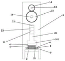
Fig. 1 is a schematic front view of the present invention;
fig. 2 is a schematic side view of the present invention;
fig. 3 is a schematic top view of the pressing plate of the present invention.
In the figure: 1. a support plate; 101. a first slot; 102. a second slot; 2. a mold plate; 3. a compression spring; 4. a pressing plate; 5. a toothed plate; 6. a cylinder; 7. a push rod; 8. a first motor; 9. a first rotating shaft; 10. a first gear; 11. a support plate; 12. a second motor; 13. a second rotating shaft; 14. a second gear; 15. a third gear; 16. a third rotating shaft; 17. a connecting arm; 18. a rotating arm; 19. a first connection block; 20. a push arm; 21. a second connecting block; 22. a pressure block; 23. and a limiting arm.
Detailed Description
In describing the present invention in further detail with reference to the drawings, it is to be understood that the terms "center", "longitudinal", "lateral", "length", "width", "thickness", "upper", "lower", "front", "rear", "left", "right", "vertical", "horizontal", "top", "bottom", "inner", "outer", "clockwise", "counterclockwise", and the like indicate orientations or positional relationships based on the orientations or positional relationships shown in the drawings, and are used merely for convenience of description and to simplify the description, but do not indicate or imply that the equipment or components referred to must have a particular orientation, be constructed and operated in a particular orientation, and therefore should not be considered as limiting the present invention.
Referring to fig. 1, 2 and 3, a rapid prototyping rubber press comprises: the device comprises a support plate 1, wherein a first groove 101 is formed in the support plate 1, a second groove 102 is formed below the first groove 101, a mold plate 2 is arranged at the bottom end of the support plate 1, compression springs 3 are arranged at two ends of the upper surface of the mold plate 2, a pressing plate 4 is arranged above the compression springs 3, the middle position of the pressing plate 4 is hollowed, the pressing plate 4 slides in the second groove 102, toothed plates 5 are arranged at two sides of the pressing plate 4, an air cylinder 6 is arranged at the outer side of the support plate 1, the output end of the air cylinder 6 is connected with one end of a push rod 7, the other end of the push rod 7 is connected with a first motor 8, the output end of the first motor 8 is connected with one end of a first rotating shaft 9, the other end of the first rotating shaft 9 is connected with a first gear 10, the first gear 10 can be meshed with the toothed plates 5, a support plate 11 is arranged at one side of the top end of the support plate 1, a second motor 12 is arranged on the support plate 11, and the output end of the second motor 12 is connected with one end of a second rotating shaft 13, the other end of the second rotating shaft 13 is connected with a second gear 14, the second gear 14 is meshed with a third gear 15, the third gear 15 is connected with one end of a third rotating shaft 16, the other end of the third rotating shaft 16 is connected with one end of a connecting arm 17, the other end of the connecting arm 17 is connected with a rotating arm 18, a first connecting block 19 is arranged in the middle of the rotating arm 18, one end of a pushing arm 20 is connected with the first connecting block 19, the other end of the pushing arm 20 is connected with a second connecting block 21, the second connecting block 21 is arranged in the middle of the upper surface of a pressure block 22, limiting arms 23 are connected on two sides of the pressure block 22, the limiting arms 23 can slide in a first groove 101, the output end of the second motor 12 is connected with the second rotating shaft 13 through arranging a second motor 12, so that the second rotating shaft 13 can be driven to rotate, and by arranging the second rotating shaft 13, the second rotating shaft 13 is connected with a second gear 14, so that the second rotating shaft 13 rotates to drive the second gear 14 to rotate, and then the second motor 12 drives the second gear 14 to rotate, and is engaged with the third gear 15 by arranging the second gear 14, thereby, the second gear 14 rotates to drive the third gear 15 to rotate, by arranging the third gear 15, the third gear 15 is connected with the third rotating shaft 16, thereby, the third gear 15 rotates to drive the third rotating shaft 16 to rotate, by arranging the third rotating shaft 16, the third rotating shaft 16 is connected with the connecting arm 17, thereby, the third rotating shaft 16 rotates to drive the connecting arm 17 to rotate, by arranging the connecting arm 17, the connecting arm 17 is connected with the rotating arm 18, thereby, the connecting arm 17 rotates to drive the rotating arm 18 to rotate circularly, and further, the second motor 12 can drive the rotating arm 18 to rotate circularly, because the rotating arm 18 is connected with the pushing arm 20 through the first connecting block 19, thereby, the rotating arm 18 rotates circularly to drive the pushing arm 20 to move up and down, because the pushing arm 20 is connected with the pressure block 22 through the second connecting block 21, and the pressure block 22 is connected with a limit arm 23, the limit arm 23 can slide in the first slot 101, so that the pushing arm 20 can move up and down to drive the pressure block 22 to move up and down with the first slot 101 as a limit, the pressure block 22 can move up and down for die-molding of a die, the die can be placed between the pressing plate 4 and the die plate 2 by arranging the pressing plate 4 and the die plate 2, when the die is placed between the pressing plate 4 and the die plate 2, the output end of the cylinder 6 is connected with a push rod 7 by arranging the cylinder 6, so that the cylinder 6 can drive the salient point 7 to move, the first motor 8 is connected by arranging the push rod 7, so that the push rod 7 can drive the electrometer motor 8 to move, the cylinder 6 is started to drive the first motor 8 to move towards the direction close to the die, and by arranging the first gear 10, the first gear 10 is connected with the output end of the first motor 8 by a first rotating shaft 9, the first gear 10 can be meshed with the toothed plate 5, so that the cylinder 6 moves the first motor 8 to enable the first gear 10 to be meshed with the toothed plate 5, then the first motor 8 is started to drive the first gear 10 to rotate, the pressing plate 4 is enabled to move downwards, a mold arranged between the pressing plate 4 and the mold plate 2 is fixed, as the pressing plate 4 adopts a middle hollow structure, then the pressure is fast 22 to press the mold, the mold compression molding work is completed, then the cylinder 6 pushes the first motor 8 to move towards the direction away from the mold, the first motor 8 drives the first gear 10 to move towards the direction away from the mold, so that the meshing relation between the first gear 10 and the toothed plate 5 is removed, the pressing plate 4 can be bounced under the action of the compression spring 3 by arranging the compression spring 3, so that the mold arranged between the pressing plate 4 and the mold plate 2 can be replaced, when the mold needs to be replaced again, only the steps need to be repeated, the whole process of replacing the die is convenient and time-saving, and the processing efficiency is improved.
The working principle is as follows: when the die pressing device is used, a die is placed between the pressing plate 4 and the die plate 2, then the air cylinder 6 is started, the air cylinder 6 drives the first gear to move towards the direction close to the die, the first gear 10 is meshed with the toothed plate 5, then the first motor 8 is started, the first motor 8 drives the first gear 10 to rotate, so that the toothed plate 5 is driven to move, the toothed plate 5 moves to drive the pressing plate 4 to move, so that the die placed between the pressing plate 4 and the die plate 2 can be fixed, then the second motor 12 is started, the second motor 12 drives the second gear 14 to rotate, the second gear 14 is meshed with the third gear 15, the second gear 14 rotates to drive the third gear 15 to rotate, the third gear 15 rotates to drive the rotating arm 18 to rotate circularly, the rotating arm 18 rotates to drive the pushing arm 20 to move up and down, the pushing arm 20 moves up and down to drive the pressure block 22 to move up and down, because the pressing plate 4 adopts a middle hollow structure, pressure block 22 reciprocates and can accomplish the moulding-die shaping work to the mould, when needs are changed the mould, start cylinder 6, cylinder 6 drives first motor 8 and removes to keeping away from the mould direction, first motor 8 drives first gear 10 and removes to keeping away from the mould direction, thereby the meshing relation of first gear 10 and pinion rack 5 has been removed, under compression spring 3's effect, can upwards bounce according to clamp plate 4, be convenient for take out the mould of placing between clamp plate 4 and mould board 2 afterwards, accomplish the change of mould, whole mould change step process is convenient to save time, and the machining efficiency is improved.
The foregoing shows and describes the general principles, essential features, and advantages of the invention. It should be understood by those skilled in the art that the present invention is not limited by the above embodiments, and the above embodiments and descriptions in the specification are only preferred examples of the present invention, and are not intended to limit the present invention. The scope of the invention is defined by the appended claims and equivalents thereof.
Claims (6)
1. The utility model provides a rapid prototyping rubber press which characterized in that: the method comprises the following steps: the extension board, first fluting has been seted up to the extension board, first fluting below is provided with the second fluting, extension board bottom position is provided with the mould board, mould board upper surface both ends are provided with compression spring, the compression spring top is provided with presses the clamp plate, press clamp plate intermediate position fretwork, press the clamp plate to slide in the second fluting, press clamp plate both sides are provided with the pinion rack, the extension board outside is provided with the cylinder, the cylinder output is connected with push rod one end, the push rod other end is connected with first motor, the first motor output is connected with first pivot one end, the first pivot other end is connected with first gear, first gear can with pinion rack intermeshing.
2. A rapid prototyping rubber press as in claim 1 wherein: a supporting plate is arranged on one side of the top end of the supporting plate, and a second motor is mounted on the supporting plate.
3. A rapid prototyping rubber press as in claim 2 wherein: the output end of the second motor is connected with one end of a second rotating shaft, the other end of the second rotating shaft is connected with a second gear, and the second gear is meshed with a third gear.
4. A rapid prototyping rubber press as in claim 3 wherein: the third gear is connected with one end of a third rotating shaft, the other end of the third rotating shaft is connected with one end of a connecting arm, the other end of the connecting arm is connected with a rotating arm, and a first connecting block is arranged in the middle of the rotating arm.
5. A rapid prototyping rubber press as in claim 4 wherein: the first connecting block is connected with one end of a pushing arm, the other end of the pushing arm is connected with a second connecting block, and the second connecting block is arranged in the middle of the upper surface of the pressure block.
6. A rapid prototyping rubber press as claimed in claim 5 wherein: and two sides of the pressure block are connected with limiting arms, and the limiting arms can slide in the first grooves.
Priority Applications (1)
| Application Number | Priority Date | Filing Date | Title |
|---|---|---|---|
| CN202120334119.8U CN214644308U (en) | 2021-02-05 | 2021-02-05 | Quick shaping rubber press |
Applications Claiming Priority (1)
| Application Number | Priority Date | Filing Date | Title |
|---|---|---|---|
| CN202120334119.8U CN214644308U (en) | 2021-02-05 | 2021-02-05 | Quick shaping rubber press |
Publications (1)
| Publication Number | Publication Date |
|---|---|
| CN214644308U true CN214644308U (en) | 2021-11-09 |
Family
ID=78446532
Family Applications (1)
| Application Number | Title | Priority Date | Filing Date |
|---|---|---|---|
| CN202120334119.8U Expired - Fee Related CN214644308U (en) | 2021-02-05 | 2021-02-05 | Quick shaping rubber press |
Country Status (1)
| Country | Link |
|---|---|
| CN (1) | CN214644308U (en) |
-
2021
- 2021-02-05 CN CN202120334119.8U patent/CN214644308U/en not_active Expired - Fee Related
Similar Documents
| Publication | Publication Date | Title |
|---|---|---|
| CN113477821A (en) | Machining stamping equipment | |
| CN217166119U (en) | Auxiliary structure of stamping die | |
| CN201026670Y (en) | Aluminium alloyed door/window profile press machine | |
| CN214644308U (en) | Quick shaping rubber press | |
| CN219766482U (en) | Stamping forming device | |
| CN219597862U (en) | Automobile stamping part die | |
| CN111545620A (en) | Stamping forming process for sheet metal part | |
| CN218108986U (en) | Full-automatic aluminum alloy profile hydraulic punching machine | |
| CN110560684A (en) | pressing die and preparation method of powder material | |
| CN216911742U (en) | Die manufacturing device | |
| CN214639493U (en) | Cold stamping forming's heat dissipation stamping workpiece | |
| CN215845070U (en) | Rod body bending device | |
| CN211938687U (en) | Stamping die suitable for notebook computer keyboard frame | |
| CN215471642U (en) | Stamping mechanism of rubber press | |
| CN114192674A (en) | Rotary traceless bending die for mounting bracket of electric drive rear axle motor of automobile and machining process of rotary traceless bending die | |
| CN215471641U (en) | Rubber press takes off material and collects mechanism | |
| CN107962143B (en) | Pin shaft heading machine | |
| CN220426533U (en) | Stamping die for stamping metal products | |
| CN204974966U (en) | Part forming die | |
| CN113305197B (en) | Universal mechanical curved surface sheet metal part forming device and forming method thereof | |
| CN217252086U (en) | High-strength lightweight titanium alloy pipe machining die | |
| CN210387064U (en) | Steel sheet punching press mould of bending | |
| CN217141840U (en) | Bending device for open type fixed table press | |
| CN219130528U (en) | Digital stamping die capable of rapidly demolding | |
| CN211591031U (en) | Stamping die for household electrical appliances of convenient quick unloading |
Legal Events
| Date | Code | Title | Description |
|---|---|---|---|
| GR01 | Patent grant | ||
| GR01 | Patent grant | ||
| CF01 | Termination of patent right due to non-payment of annual fee | ||
| CF01 | Termination of patent right due to non-payment of annual fee |
Granted publication date: 20211109 |