WO2014167661A1 - ハウジング装着中空糸膜モジュール - Google Patents
ハウジング装着中空糸膜モジュール Download PDFInfo
- Publication number
- WO2014167661A1 WO2014167661A1 PCT/JP2013/060787 JP2013060787W WO2014167661A1 WO 2014167661 A1 WO2014167661 A1 WO 2014167661A1 JP 2013060787 W JP2013060787 W JP 2013060787W WO 2014167661 A1 WO2014167661 A1 WO 2014167661A1
- Authority
- WO
- WIPO (PCT)
- Prior art keywords
- housing
- hollow fiber
- fiber membrane
- membrane module
- peripheral surface
- Prior art date
- Legal status (The legal status is an assumption and is not a legal conclusion. Google has not performed a legal analysis and makes no representation as to the accuracy of the status listed.)
- Ceased
Links
Images




Classifications
-
- B—PERFORMING OPERATIONS; TRANSPORTING
- B01—PHYSICAL OR CHEMICAL PROCESSES OR APPARATUS IN GENERAL
- B01D—SEPARATION
- B01D63/00—Apparatus in general for separation processes using semi-permeable membranes
- B01D63/02—Hollow fibre modules
-
- B—PERFORMING OPERATIONS; TRANSPORTING
- B01—PHYSICAL OR CHEMICAL PROCESSES OR APPARATUS IN GENERAL
- B01D—SEPARATION
- B01D2313/00—Details relating to membrane modules or apparatus
- B01D2313/04—Specific sealing means
- B01D2313/041—Gaskets or O-rings
-
- B—PERFORMING OPERATIONS; TRANSPORTING
- B01—PHYSICAL OR CHEMICAL PROCESSES OR APPARATUS IN GENERAL
- B01D—SEPARATION
- B01D2313/00—Details relating to membrane modules or apparatus
- B01D2313/56—Specific mechanisms for loading the membrane in a module
Definitions
- the present invention relates to a hollow fiber membrane module. More specifically, the present invention relates to a hollow fiber membrane module in which a bundled tube containing a hollow fiber membrane group is attached to a housing via a seal member.
- porous hollow fiber membranes such as porous ceramic hollow fiber membranes and porous carbon hollow fiber membranes are effectively used as liquid separation membranes and gas separation membranes.
- a through-hole drilling in which a porous ceramic hollow fiber membrane group is fitted to the bundled tube end
- the present applicant has previously proposed a porous ceramic hollow fiber membrane module or the like that is inserted into a through hole of a flat plate and the outer surface side of the through hole drilled flat plate is covered with a glass sealing material.
- the bundled tube is basically cylindrical, an O-ring as a seal member is disposed in a groove for fitting a seal member provided on the inner peripheral surface of the housing, and sealing is performed when the housing is mounted ( Patent Documents 1 and 2).
- An O-ring or the like is generally used as a seal member on such a cylindrical outer peripheral surface.
- FIGS. 4 to 5 after the insertion from the state before the bundled tube is inserted into the housing (FIG. 4).
- the O-ring 1 passes through the seal portion where the O-ring 2 is to be sealed.
- the mounting property at the time of insertion of the module is poor, and as a result, the O-ring may be twisted, which may cause a problem that the sealing property is deteriorated. This is the same when two grooves for fitting the seal member are provided not on the outer peripheral surface of the bundled tube but on the inner peripheral surface of the housing.
- the diameter of the O-ring 2 is made larger than that of the O-ring 1 as shown in FIGS. 6 to 7, and until the bundled tube is inserted into the housing shown in FIG. It is also conceivable to improve the mountability by eliminating the insertion resistance when passing through the sealing portion and finally setting the bundled tube into the housing (FIG. 7). However, for a larger diameter O-ring, a larger space is required in the housing, and the cost is higher than when an O-ring having the same diameter is used.
- An object of the present invention is to provide a housing-attached hollow fiber membrane module in which the same seal member, for example, an O-ring having the same diameter size, is used and the mounting property to the housing is improved.
- An object of the present invention is to insert a hollow fiber membrane module composed of a bundled tube containing a hollow fiber membrane through a hollow fiber membrane module insertion portion provided at one end of a housing, so that the outer peripheral surface of the bundled tube and the bundled tube are inserted.
- a hollow fiber membrane module composed of a bundled tube containing a hollow fiber membrane through a hollow fiber membrane module insertion portion provided at one end of a housing, so that the outer peripheral surface of the bundled tube and the bundled tube are inserted.
- the housing-attached hollow fiber membrane module in which at least two identical seal members are arranged in the gap between the housing inner peripheral surface and the housing, and the housing is attached to the housing.
- Seals provided on the inner peripheral surface of the end located on the opposite side to the hollow fiber membrane module insertion portion of the housing and on the outer peripheral surface of the bundled tube corresponding to the end located on the hollow fiber membrane module insertion portion side of the housing This is achieved by the housing-mounted hollow fiber membrane module in which the hollow fiber membrane module is mounted on the housing by mounting the seal members in the member mounting grooves.
- the housing-attached hollow fiber membrane module comprises a hollow fiber membrane module comprising a bundled tube containing hollow fiber membranes such as a porous ceramic hollow fiber membrane and a porous carbon hollow fiber membrane, and an outer peripheral surface of the bundled tube.
- one groove for fitting the seal member is provided on the inner peripheral surface of the end located on the opposite side of the hollow fiber membrane module insertion portion of the housing, and the other groove for fitting the seal member is provided on the hollow fiber membrane module insertion portion.
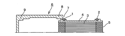
- FIG. 2 is a half-cut cross-sectional view showing one aspect of mounting the hollow fiber membrane module according to the present invention on the housing as a state during insertion of the hollow fiber membrane module into the housing.
- FIG. 2 is a half-cut cross-sectional view showing one aspect of mounting the hollow fiber membrane module according to the present invention on the housing as a state after the hollow fiber membrane module is inserted into the housing.
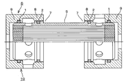
- FIG. 2 is a half-cut sectional view showing a state in which both ends of the hollow fiber membrane module according to the present invention are mounted in separate housings as a state after the hollow fiber membrane module is mounted in the housing.
- FIG. 6 is a half-cut sectional view showing a state in which a conventional hollow fiber membrane module is mounted on a housing as a state before the hollow fiber membrane module is inserted into the housing.
- FIG. 6 is a half-sectional view showing a state in which a conventional hollow fiber membrane module is mounted on a housing as a state after the hollow fiber membrane module is inserted into the housing. It is a half-cut sectional view which shows the other aspect which mounts the conventional hollow fiber membrane module in a housing as a state in the middle of hollow fiber membrane module insertion in a housing.
- FIG. 7 is a half-cut sectional view showing another aspect of mounting the conventional hollow fiber membrane module on the housing as a state after the hollow fiber membrane module is inserted into the housing.
- the housing-mounted hollow fiber membrane module includes a hollow fiber membrane module 5 including a bundled tube 4 containing the hollow fiber membrane 3. At least two sealing members such as O-rings are arranged in the gap with the surface and are mounted on the housing 6.
- FIGS. 1 shows a state in the middle of inserting the hollow fiber membrane module into the housing
- FIG. 2 shows a state after the insertion.
- the housing 6 in addition to an integral housing that can accommodate the entire hollow fiber membrane module 5 shown in FIGS. 1 and 2 in the tube, both ends of the hollow fiber membrane module 5 as shown in FIG. Any of the divided housings can be used in which the parts are accommodated separately.
- the seal member has the same shape and size, and here, the O-rings 1 and 2 have the same diameter (cross-sectional diameter and inner diameter).
- a groove for fitting a seal member is provided on the outer peripheral surface of the bundled tube corresponding to the housing one end 8 located.
- Each of the grooves for receiving the O-rings 1 and 2 has the same dimensions, that is, the groove depth and the groove width, and the groove provided in the other end 9 of the housing is formed by denting the inner peripheral surface of the housing.
- the groove provided in the portion 8 is formed by providing a protruding portion having a recess on the outer peripheral surface of the bundled tube.
- the depth of the groove for fitting the O-rings 1 and 2 is set to be smaller than the diameter of the rubber cross section of the O-rings 1 and 2, thereby allowing the hollow fiber membrane module 5 to be watertight in the housing 6. It becomes possible to attach with.
- the inner peripheral surface of the housing end 9 located on the opposite side of the hollow fiber membrane module insertion portion 7 and the housing end on the hollow fiber membrane module insertion portion 7 side are also provided.
- a groove for fitting a seal member is provided on the outer peripheral surface of the bundled tube corresponding to the portion 8.
- the depth of the groove for fitting the O-rings 1 and 2 is set smaller than the diameter of the rubber cross section of the O-rings 1 and 2, whereby the hollow fiber membrane module 5 is sealed in the housing 6. It becomes possible to attach with.
- the housing end provided with the groove for fitting the seal member located on the inner peripheral surface of the housing or the outer peripheral surface of the bundled tube is defined as the bundled tube when the bundled tube is mounted. It refers to the position facing the bundled tube side end excluding the portion provided with the air or fluid inflow / outflow holes provided in the tube side peripheral portion. That is, the gap generated between the inner peripheral surface of the housing and the outer peripheral surface of the bundled tube generated in this part is reliably sealed using a seal member, so that the fluid before and after passing through the hollow fiber is completely isolated. be able to.
Landscapes
- Chemical & Material Sciences (AREA)
- Chemical Kinetics & Catalysis (AREA)
- Separation Using Semi-Permeable Membranes (AREA)
Abstract
中空糸膜を収容した束着管からなる中空糸膜モジュールを、ハウジングの一端に設けられた中空糸膜モジュール挿入部より挿入させ、束着管外周面と束着管を収容するハウジング内周面との間隙に同一のシール部材を少なくとも2個配してハウジングに装着せしめたハウジング装着中空糸膜モジュールにおいて、 ハウジングの中空糸膜モジュール挿入部とは反対側に位置する端部の内周表面およびハウジングの中空糸膜モジュール挿入部側に位置する端部に対応する束着管外周表面にそれぞれ設けられたシール部材嵌装用の溝にシール部材をそれぞれ嵌装せしめることによって、中空糸膜モジュールをハウジングに装着せしめたハウジング装着中空糸膜モジュール。このハウジング装着中空糸膜モジュールは、同一のシール部材を使用したうえで、ハウジングへの装着性を改善せしめる。
Description
本発明は、中空糸膜モジュールに関する。さらに詳しくは、中空糸膜群を収容している束着管を、シール部材を介してハウジングへ装着せしめた中空糸膜モジュールに関する。
現在、多孔質セラミックス中空糸膜、多孔質炭素中空糸膜などの多孔質中空糸膜は、液体分離膜、気体分離膜として有効に用いられている。このような多孔質中空糸膜を使用する場合には、これらを固定し、密封する必要があり、そのために多孔質セラミックス中空糸膜群を束着管端部に嵌装させた貫通孔穿設平板の貫通孔に挿入し、貫通孔穿設平板の外面側をガラスシール材で被覆した多孔質セラミックス中空糸膜モジュールなどが、先に本出願人によって提案されている。ここで束着管は、基本的には円筒形なので、ハウジング内周表面に設けられたシール部材嵌装用の溝にシール部材であるOリングを配し、ハウジング装着時のシールを行っている(特許文献1~2)。
ここで、モジュールをハウジングに装着するに際しては、シール部材の締付力を受けながらモジュールをハウジング内に挿入する必要がある。このような円筒形外周面でのシール部材としては、一般にOリング等が用いられるが、例えば図4~5に示されるようにハウジングへの束着管挿入前(図4)の状態から挿入後(図5)の状態にかけて、Oリング1はOリング2がシールすることとなるシール部位を通過することとなる。このためモジュールの挿入時の装着性が悪く、その結果Oリングが捩れるなどして、シール性を低下させるという問題を生じるおそれがある。このことは、束着管外周表面ではなくハウジング内周表面にシール部材嵌装用の溝を2箇所設けた場合も同様である。
ここで、図6~7に示されるようにOリング1よりもOリング2の径を大きくし、図6に示されるハウジングへの束着管の挿入途中まで、すなわちOリング1がOリング2のシール部位を通過する際の挿入抵抗をなくし、最終的にハウジングへの束着管挿入後(図7)の状態とすることで装着性を向上することも考えられる。しかしながら、より大きな径のOリングに対しては、ハウジング内により大きなスペースが必要となり、またコストに関しても同じ径サイズのOリングを使用するときと比較して高くなってしまう。
本発明の目的は、同一のシール部材、例えば同じ径サイズのOリングを使用したうえで、ハウジングへの装着性を改善せしめたハウジング装着中空糸膜モジュールを提供することにある。
かかる本発明の目的は、中空糸膜を収容した束着管からなる中空糸膜モジュールを、ハウジングの一端に設けられた中空糸膜モジュール挿入部より挿入させ、束着管外周面と束着管を収容するハウジング内周面との間隙に同一のシール部材を少なくとも2個配してハウジングに装着せしめたハウジング装着中空糸膜モジュールにおいて、
ハウジングの中空糸膜モジュール挿入部とは反対側に位置する端部の内周表面およびハウジングの中空糸膜モジュール挿入部側に位置する端部に対応する束着管外周表面にそれぞれ設けられたシール部材嵌装用の溝にシール部材をそれぞれ嵌装せしめることによって、中空糸膜モジュールをハウジングに装着せしめたハウジング装着中空糸膜モジュールによって達成される。
ハウジングの中空糸膜モジュール挿入部とは反対側に位置する端部の内周表面およびハウジングの中空糸膜モジュール挿入部側に位置する端部に対応する束着管外周表面にそれぞれ設けられたシール部材嵌装用の溝にシール部材をそれぞれ嵌装せしめることによって、中空糸膜モジュールをハウジングに装着せしめたハウジング装着中空糸膜モジュールによって達成される。
本発明に係るハウジング装着中空糸膜モジュールは、多孔質セラミックス中空糸膜、多孔質炭素中空糸膜等の中空糸膜を収容した束着管からなる中空糸膜モジュールを、束着管外周面とハウジング内周面との間隙にシール部材を少なくとも2個配してハウジングに装着せしめるに際し、シール部材をいずれも同一のもの、すなわち同じ形状およびサイズとすることによって、省スペース化の維持およびコスト増加の回避を達成している。
また、一方のシール部材嵌装用の溝をハウジングの中空糸膜モジュール挿入部とは反対側に位置する端部の内周表面に設け、他方のシール部材嵌装用の溝を中空糸膜モジュール挿入部側に位置する端部に対応する束着管外周表面に設けることによって、ハウジングへ中空糸膜モジュールを装着する際の挿入抵抗を減らし、また挿入回数増加による抵抗によって生ずるシール部材の変形、破損等を防止して、中空糸膜モジュールを何回か交換して使用する場合にあっても、そのシール性を維持せしめるといったすぐれた効果を奏する。
ハウジング装着中空糸膜モジュールは、図1~3に示されるように中空糸膜3を収容した束着管4からなる中空糸膜モジュール5を、束着管4の外周面とハウジング6の内周面との間隙にOリング等のシール部材を少なくとも2個配してハウジング6に装着せしめて構成される。中空糸膜モジュールをハウジングに装着する一態様を図1~2に示す。図1は中空糸膜モジュールをハウジングに挿入している途中の状態を示し、図2は挿入後の状態を示している。ここでハウジング6としては、図1~2に示される中空糸膜モジュール5全体をその管内に収容することができる一体型のハウジングのほか、図3に示されるような中空糸膜モジュール5の両端部を別々に収容するといった分割型のハウジングのいずれも用いることができる。
シール部材としては同一の形状およびサイズのものが用いられ、ここではOリング1,2として同じ径サイズ(断面径および内径)のものが用いられている。シール部材をいずれも同一とすることによって、ハウジング内の省スペース化の維持および異なる形状あるいはサイズのシール部材を用いることによるコストの増加を回避することが可能となる。
図1~2に示される一体型のハウジングにあっては、中空糸膜モジュール挿入部7とは反対側に位置するハウジング他端部9の内周表面およびハウジング中空糸膜モジュール挿入部7側に位置するハウジング一端部8に対応する束着管外周表面にそれぞれシール部材嵌装用の溝が設けられる。Oリング1、2を収容するいずれの溝も寸法、すなわち溝深さと溝幅は同じであり、ハウジング他端部9に設けられる溝はハウジング内周表面を凹ませることにより形成され、一方ハウジング一端部8に設けられる溝は束着管外周表面に凹部を有する出張り部を設けることにより形成される。これらの図において、Oリング1,2嵌装用の溝の深さは、Oリング1,2のゴム断面の直径よりも小さく設定されており、これによって中空糸膜モジュール5をハウジング6に水密状態で装着させることが可能となる。
また、図3に示される分割型のハウジングにあっては、中空糸膜モジュール挿入部7とは反対側に位置するハウジング端部9の内周表面および中空糸膜モジュール挿入部7側のハウジング端部8に対応する束着管外周表面にそれぞれシール部材嵌装用の溝が設けられる。この場合には、各端部に少なくとも2個のシール部材を装着することが容易となるので、全体では少なくとも4個のシール部材の装着を容易に行うことができる。この図の場合にも、Oリング1,2嵌装用の溝の深さは、Oリング1,2のゴム断面の直径よりも小さく設定され、これによって中空糸膜モジュール5をハウジング6に水密状態で装着させることが可能となる。
ハウジングがこれらいずれの場合にあっても、ハウジング内周表面あるいは束着管外周表面に位置するシール部材嵌装用の溝が設けられるハウジング端部とは、束着管を装着したときに、束着管側周部に設けられている空気あるいは流体の流出入孔が設けられている部分を除く束着管側端部と相対することとなる位置を指している。すなわち、この部位に生じているハウジング内周面と束着管外周面との間に生じる間隙をシール部材を用いて確実にシールすることで、中空糸を通過する前後の流体を完全に隔離することができる。
1 Oリング
2 Oリング
3 中空糸
4 束着管
5 中空糸膜モジュール
6 ハウジング
7 中空糸膜モジュール挿入部
8 ハウジング一端部
9 ハウジング他端部
10 ハウジング装着中空糸膜モジュール
2 Oリング
3 中空糸
4 束着管
5 中空糸膜モジュール
6 ハウジング
7 中空糸膜モジュール挿入部
8 ハウジング一端部
9 ハウジング他端部
10 ハウジング装着中空糸膜モジュール
Claims (6)
- 中空糸膜を収容した束着管からなる中空糸膜モジュールを、ハウジングの一端に設けられた中空糸膜モジュール挿入部より挿入させ、束着管外周面と束着管を収容するハウジング内周面との間隙に同一のシール部材を少なくとも2個配してハウジングに装着せしめたハウジング装着中空糸膜モジュールにおいて、
ハウジングの中空糸膜モジュール挿入部とは反対側に位置する端部の内周表面およびハウジングの中空糸膜モジュール挿入部側に位置する端部に対応する束着管外周表面にそれぞれ設けられたシール部材嵌装用の溝にシール部材をそれぞれ嵌装せしめることによって、中空糸膜モジュールをハウジングに装着せしめたハウジング装着中空糸膜モジュール。 - 同一のシール部材が同じ径サイズのOリングである請求項1記載のハウジング装着中空糸膜モジュール。
- ハウジングが、中空糸膜モジュール全体をその内部に収容可能な一体型のハウジングである請求項1記載のハウジング装着中空糸膜モジュール。
- ハウジングが、中空糸膜モジュールの両端部を別々に収容可能な分割型のハウジングである請求項1記載のハウジング装着中空糸膜モジュール。
- 中空糸膜を収容した束着管からなる中空糸膜モジュールを、ハウジングの一端に設けられた中空糸膜モジュール挿入部より挿入させ、束着管外周面と束着管を収容するハウジング内周面との間隙に同一のシール部材を少なくとも2個配してハウジングに装着せしめたハウジング装着中空糸膜モジュールの製造方法において、
ハウジングの中空糸膜モジュール挿入部側に位置する端部に対応する束着管外周表面に設けられたシール部材嵌装用の溝にシール部材を嵌挿させた中空糸膜モジュールを、ハウジングの中空糸膜モジュール挿入部とは反対側に位置する端部の内周表面に設けられたシール部材嵌装用の溝にシール部材を嵌装せしめたハウジングへ装着することを特徴とするハウジング装着中空糸膜モジュールの製造方法。 - 同一のシール部材が同じ径サイズのOリングである請求項5記載のハウジング装着中空糸膜モジュールの製造方法。
Priority Applications (1)
| Application Number | Priority Date | Filing Date | Title |
|---|---|---|---|
| PCT/JP2013/060787 WO2014167661A1 (ja) | 2013-04-10 | 2013-04-10 | ハウジング装着中空糸膜モジュール |
Applications Claiming Priority (1)
| Application Number | Priority Date | Filing Date | Title |
|---|---|---|---|
| PCT/JP2013/060787 WO2014167661A1 (ja) | 2013-04-10 | 2013-04-10 | ハウジング装着中空糸膜モジュール |
Publications (1)
| Publication Number | Publication Date |
|---|---|
| WO2014167661A1 true WO2014167661A1 (ja) | 2014-10-16 |
Family
ID=51689095
Family Applications (1)
| Application Number | Title | Priority Date | Filing Date |
|---|---|---|---|
| PCT/JP2013/060787 Ceased WO2014167661A1 (ja) | 2013-04-10 | 2013-04-10 | ハウジング装着中空糸膜モジュール |
Country Status (1)
| Country | Link |
|---|---|
| WO (1) | WO2014167661A1 (ja) |
Citations (8)
| Publication number | Priority date | Publication date | Assignee | Title |
|---|---|---|---|---|
| JPS5785650U (ja) * | 1980-11-17 | 1982-05-27 | ||
| JPS59154305U (ja) * | 1983-03-31 | 1984-10-16 | 日東電工株式会社 | 流体分離装置 |
| JPS61802U (ja) * | 1984-06-08 | 1986-01-07 | 宇部興産株式会社 | 流体の分離装置の連結体 |
| JPH11512802A (ja) * | 1995-09-20 | 1999-11-02 | ホートン・インコーポレイテッド | キー接続部に用いられるロック装置 |
| JP2005224719A (ja) * | 2004-02-13 | 2005-08-25 | Nok Corp | 中空糸膜モジュール及びその製造方法 |
| JP2006142176A (ja) * | 2004-11-18 | 2006-06-08 | Nok Corp | 分離装置及びシール |
| JP2007503298A (ja) * | 2003-08-25 | 2007-02-22 | ポール・コーポレーション | ろ過装置及び交換可能なフィルタカートリッジ |
| JP2008069873A (ja) * | 2006-09-14 | 2008-03-27 | Suzuki Precion Co Ltd | バルブシート構造とその組立方法 |
-
2013
- 2013-04-10 WO PCT/JP2013/060787 patent/WO2014167661A1/ja not_active Ceased
Patent Citations (8)
| Publication number | Priority date | Publication date | Assignee | Title |
|---|---|---|---|---|
| JPS5785650U (ja) * | 1980-11-17 | 1982-05-27 | ||
| JPS59154305U (ja) * | 1983-03-31 | 1984-10-16 | 日東電工株式会社 | 流体分離装置 |
| JPS61802U (ja) * | 1984-06-08 | 1986-01-07 | 宇部興産株式会社 | 流体の分離装置の連結体 |
| JPH11512802A (ja) * | 1995-09-20 | 1999-11-02 | ホートン・インコーポレイテッド | キー接続部に用いられるロック装置 |
| JP2007503298A (ja) * | 2003-08-25 | 2007-02-22 | ポール・コーポレーション | ろ過装置及び交換可能なフィルタカートリッジ |
| JP2005224719A (ja) * | 2004-02-13 | 2005-08-25 | Nok Corp | 中空糸膜モジュール及びその製造方法 |
| JP2006142176A (ja) * | 2004-11-18 | 2006-06-08 | Nok Corp | 分離装置及びシール |
| JP2008069873A (ja) * | 2006-09-14 | 2008-03-27 | Suzuki Precion Co Ltd | バルブシート構造とその組立方法 |
Similar Documents
| Publication | Publication Date | Title |
|---|---|---|
| CN102361286A (zh) | 用于电线引出孔的密封结构和电线引出孔的密封方法 | |
| US10345049B2 (en) | Communication-type thermal conduction device | |
| JP2015513126A5 (ja) | ||
| WO2010087943A8 (en) | Dual sealing system for use with a probe | |
| TW200705767A (en) | Sealing member for an entry port | |
| BR112022018583A2 (pt) | Elemento de filtro com receptor de vedação | |
| RU2009129943A (ru) | Способ сборки иллюминатора для летательного аппарата | |
| IT201600113594A1 (it) | Gruppo di tenuta per un organo rotante | |
| ES2905223T3 (es) | Elemento de conexión para la creación de una conexión entre un perfil hueco y otra parte de construcción | |
| CA2909870C (en) | Drill pipe | |
| WO2014167661A1 (ja) | ハウジング装着中空糸膜モジュール | |
| JP5553073B2 (ja) | ハウジング装着中空糸膜モジュール | |
| PL1926546T3 (pl) | Urządzenie oddzielające z membraną z włókien wydrążonych | |
| US9303769B2 (en) | Cartridgised mixer seal | |
| CN104754190A (zh) | 一种压力平衡式井下摄像仪密封结构 | |
| CN107725921B (zh) | 一种接头组件及管路连接方法 | |
| US20140353968A1 (en) | Positioning mechanism and expansion assembly thereof | |
| CN204677829U (zh) | 水路扩展单向阀、集成水路板及净水机 | |
| US20180154313A1 (en) | Fixture device for membrane assembly and related methods | |
| RU2013139553A (ru) | Уплотнение стыка коллектора | |
| CN202580322U (zh) | 一种用于地铁前照灯的线缆密封结构 | |
| CN204828962U (zh) | 一种工艺设备及其工艺设备管道穿板装置 | |
| JP2007037364A (ja) | ケーブルグランド | |
| CN216381580U (zh) | 保护盖及具有其的排气管路组件 | |
| CN217559752U (zh) | 一种千米级水下光源 |
Legal Events
| Date | Code | Title | Description |
|---|---|---|---|
| 121 | Ep: the epo has been informed by wipo that ep was designated in this application |
Ref document number: 13882051 Country of ref document: EP Kind code of ref document: A1 |
|
| NENP | Non-entry into the national phase |
Ref country code: DE |
|
| 122 | Ep: pct application non-entry in european phase |
Ref document number: 13882051 Country of ref document: EP Kind code of ref document: A1 |
|
| NENP | Non-entry into the national phase |
Ref country code: JP |