WO2014167619A1 - ホログラム記録再生装置及びホログラム再生方法 - Google Patents
ホログラム記録再生装置及びホログラム再生方法 Download PDFInfo
- Publication number
- WO2014167619A1 WO2014167619A1 PCT/JP2013/060574 JP2013060574W WO2014167619A1 WO 2014167619 A1 WO2014167619 A1 WO 2014167619A1 JP 2013060574 W JP2013060574 W JP 2013060574W WO 2014167619 A1 WO2014167619 A1 WO 2014167619A1
- Authority
- WO
- WIPO (PCT)
- Prior art keywords
- incident angle
- unit
- hologram recording
- orthogonal
- recording medium
- Prior art date
- Legal status (The legal status is an assumption and is not a legal conclusion. Google has not performed a legal analysis and makes no representation as to the accuracy of the status listed.)
- Ceased
Links
Images


















Classifications
-
- G—PHYSICS
- G11—INFORMATION STORAGE
- G11B—INFORMATION STORAGE BASED ON RELATIVE MOVEMENT BETWEEN RECORD CARRIER AND TRANSDUCER
- G11B7/00—Recording or reproducing by optical means, e.g. recording using a thermal beam of optical radiation by modifying optical properties or the physical structure, reproducing using an optical beam at lower power by sensing optical properties; Record carriers therefor
- G11B7/08—Disposition or mounting of heads or light sources relatively to record carriers
- G11B7/083—Disposition or mounting of heads or light sources relatively to record carriers relative to record carriers storing information in the form of optical interference patterns, e.g. holograms
-
- G—PHYSICS
- G03—PHOTOGRAPHY; CINEMATOGRAPHY; ANALOGOUS TECHNIQUES USING WAVES OTHER THAN OPTICAL WAVES; ELECTROGRAPHY; HOLOGRAPHY
- G03H—HOLOGRAPHIC PROCESSES OR APPARATUS
- G03H1/00—Holographic processes or apparatus using light, infrared or ultraviolet waves for obtaining holograms or for obtaining an image from them; Details peculiar thereto
- G03H1/22—Processes or apparatus for obtaining an optical image from holograms
- G03H1/2286—Particular reconstruction light ; Beam properties
-
- G—PHYSICS
- G11—INFORMATION STORAGE
- G11B—INFORMATION STORAGE BASED ON RELATIVE MOVEMENT BETWEEN RECORD CARRIER AND TRANSDUCER
- G11B19/00—Driving, starting, stopping record carriers not specifically of filamentary or web form, or of supports therefor; Control thereof; Control of operating function ; Driving both disc and head
- G11B19/20—Driving; Starting; Stopping; Control thereof
-
- G—PHYSICS
- G11—INFORMATION STORAGE
- G11B—INFORMATION STORAGE BASED ON RELATIVE MOVEMENT BETWEEN RECORD CARRIER AND TRANSDUCER
- G11B7/00—Recording or reproducing by optical means, e.g. recording using a thermal beam of optical radiation by modifying optical properties or the physical structure, reproducing using an optical beam at lower power by sensing optical properties; Record carriers therefor
- G11B7/08—Disposition or mounting of heads or light sources relatively to record carriers
- G11B7/085—Disposition or mounting of heads or light sources relatively to record carriers with provision for moving the light beam into, or out of, its operative position or across tracks, otherwise than during the transducing operation, e.g. for adjustment or preliminary positioning or track change or selection
- G11B7/08547—Arrangements for positioning the light beam only without moving the head, e.g. using static electro-optical elements
- G11B7/08564—Arrangements for positioning the light beam only without moving the head, e.g. using static electro-optical elements using galvanomirrors
-
- G—PHYSICS
- G03—PHOTOGRAPHY; CINEMATOGRAPHY; ANALOGOUS TECHNIQUES USING WAVES OTHER THAN OPTICAL WAVES; ELECTROGRAPHY; HOLOGRAPHY
- G03H—HOLOGRAPHIC PROCESSES OR APPARATUS
- G03H1/00—Holographic processes or apparatus using light, infrared or ultraviolet waves for obtaining holograms or for obtaining an image from them; Details peculiar thereto
- G03H1/04—Processes or apparatus for producing holograms
- G03H1/10—Processes or apparatus for producing holograms using modulated reference beam
- G03H1/12—Spatial modulation, e.g. ghost imaging
-
- G—PHYSICS
- G03—PHOTOGRAPHY; CINEMATOGRAPHY; ANALOGOUS TECHNIQUES USING WAVES OTHER THAN OPTICAL WAVES; ELECTROGRAPHY; HOLOGRAPHY
- G03H—HOLOGRAPHIC PROCESSES OR APPARATUS
- G03H1/00—Holographic processes or apparatus using light, infrared or ultraviolet waves for obtaining holograms or for obtaining an image from them; Details peculiar thereto
- G03H1/26—Processes or apparatus specially adapted to produce multiple sub- holograms or to obtain images from them, e.g. multicolour technique
- G03H1/2645—Multiplexing processes, e.g. aperture, shift, or wavefront multiplexing
- G03H1/265—Angle multiplexing; Multichannel holograms
-
- G—PHYSICS
- G11—INFORMATION STORAGE
- G11B—INFORMATION STORAGE BASED ON RELATIVE MOVEMENT BETWEEN RECORD CARRIER AND TRANSDUCER
- G11B7/00—Recording or reproducing by optical means, e.g. recording using a thermal beam of optical radiation by modifying optical properties or the physical structure, reproducing using an optical beam at lower power by sensing optical properties; Record carriers therefor
- G11B2007/0003—Recording, reproducing or erasing systems characterised by the structure or type of the carrier
- G11B2007/0009—Recording, reproducing or erasing systems characterised by the structure or type of the carrier for carriers having data stored in three dimensions, e.g. volume storage
-
- G—PHYSICS
- G11—INFORMATION STORAGE
- G11B—INFORMATION STORAGE BASED ON RELATIVE MOVEMENT BETWEEN RECORD CARRIER AND TRANSDUCER
- G11B7/00—Recording or reproducing by optical means, e.g. recording using a thermal beam of optical radiation by modifying optical properties or the physical structure, reproducing using an optical beam at lower power by sensing optical properties; Record carriers therefor
- G11B7/002—Recording, reproducing or erasing systems characterised by the shape or form of the carrier
- G11B7/0037—Recording, reproducing or erasing systems characterised by the shape or form of the carrier with discs
-
- G—PHYSICS
- G11—INFORMATION STORAGE
- G11B—INFORMATION STORAGE BASED ON RELATIVE MOVEMENT BETWEEN RECORD CARRIER AND TRANSDUCER
- G11B7/00—Recording or reproducing by optical means, e.g. recording using a thermal beam of optical radiation by modifying optical properties or the physical structure, reproducing using an optical beam at lower power by sensing optical properties; Record carriers therefor
- G11B7/004—Recording, reproducing or erasing methods; Read, write or erase circuits therefor
- G11B7/0065—Recording, reproducing or erasing by using optical interference patterns, e.g. holograms
-
- G—PHYSICS
- G11—INFORMATION STORAGE
- G11B—INFORMATION STORAGE BASED ON RELATIVE MOVEMENT BETWEEN RECORD CARRIER AND TRANSDUCER
- G11B7/00—Recording or reproducing by optical means, e.g. recording using a thermal beam of optical radiation by modifying optical properties or the physical structure, reproducing using an optical beam at lower power by sensing optical properties; Record carriers therefor
- G11B7/08—Disposition or mounting of heads or light sources relatively to record carriers
- G11B7/09—Disposition or mounting of heads or light sources relatively to record carriers with provision for moving the light beam or focus plane for the purpose of maintaining alignment of the light beam relative to the record carrier during transducing operation, e.g. to compensate for surface irregularities of the latter or for track following
- G11B7/095—Disposition or mounting of heads or light sources relatively to record carriers with provision for moving the light beam or focus plane for the purpose of maintaining alignment of the light beam relative to the record carrier during transducing operation, e.g. to compensate for surface irregularities of the latter or for track following specially adapted for discs, e.g. for compensation of eccentricity or wobble
- G11B7/0953—Disposition or mounting of heads or light sources relatively to record carriers with provision for moving the light beam or focus plane for the purpose of maintaining alignment of the light beam relative to the record carrier during transducing operation, e.g. to compensate for surface irregularities of the latter or for track following specially adapted for discs, e.g. for compensation of eccentricity or wobble to compensate for eccentricity of the disc or disc tracks
Definitions
- the present invention relates to an apparatus for performing recording or reproduction using holography and a hologram reproduction method.
- the Blu-ray Disc (TM) standard using a blue-violet semiconductor laser has made it possible to commercialize an optical disc having a recording capacity of about 50 GB even for consumer use.
- HDD Hard Disk Drive
- Hologram recording technology is a method in which signal light having page data information two-dimensionally modulated by a spatial light modulator is superimposed on reference light inside the recording medium, and the interference fringe pattern generated at that time is placed in the recording medium. This is a technique for recording information on a recording medium by causing refractive index modulation.
- the hologram recorded in the recording medium acts like a diffraction grating to generate diffracted light. This diffracted light is reproduced as the same light including the recorded signal light and phase information.
- Regenerated signal light is detected two-dimensionally at high speed using a photodetector such as a CMOS or CCD.
- a photodetector such as a CMOS or CCD.
- the hologram recording technique enables two-dimensional information to be recorded on the optical recording medium at once by one hologram and further reproduces this information. Since the page data can be overwritten, large-capacity and high-speed information recording / reproduction can be achieved.
- the shape of the recording medium 1 is, for example, a disk shape, which is fixed to the spindle motor 200 by a clamp mechanism, and the spindle motor 200 is driven to rotate so that the coherent beam is irradiated on the recording medium.
- the spindle motor 200 is fixed to the sled motor 201, and the sled motor 201 rotates and feeds the coherent beam on the recording medium.
- the irradiation position can be moved in the radial direction as well.
- hologram recording One major advantage of hologram recording is that it can record large amounts of data. However, when the increase in recording capacity is pursued, it is necessary to improve the accuracy of positioning control of the position where signal light or reference light is irradiated more than before.
- eccentricity becomes a problem as an example.
- Eccentricity means that the center of rotation of the spindle motor and the center of the disc-shaped hologram recording medium do not coincide.
- the cause of the eccentricity is caused by a combination of the eccentricity of the hologram recording medium itself and the eccentricity of the hologram recording medium fixing portion attached to the rotation shaft of the spindle motor, both of which are caused by the manufacturing process. . Therefore, every time the hologram recording medium is inserted into the hologram recording / reproducing apparatus, the degree of eccentricity changes.
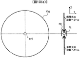
- the radius r is controlled by a sled motor and the rotation angle ⁇ is controlled by a spindle motor to move the hologram recording medium and change the position where the signal light or reference light is irradiated.
- FIG. 25A shows an ideal reference light irradiation position when there is no eccentricity, and considers a case where a hologram recorded with a radius r and a rotation angle ⁇ is reproduced.
- the point O is the center of the disc-shaped hologram recording medium, and the point P is an ideal reference light irradiation position.
- a hologram is recorded at the point P.
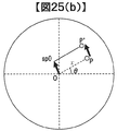
- FIG. 25 (b) shows the hologram reproduction position when eccentricity exists.
- the center of rotation sp0 of the spindle motor does not coincide with the center O of the disc-shaped hologram recording medium due to eccentricity.
- the reference light irradiation position is the position P '. Since the actual hologram is recorded at the point P, the reference light is not irradiated to an appropriate position during reproduction. Thus, the reference light irradiation position P ′ is shifted by the amount of eccentricity ⁇ p.
- the eccentricity amount In the prior art, by controlling the amount of eccentricity ⁇ p caused by the manufacturing process, no problem occurs even if this difference ⁇ p occurs. That is, the amount of eccentricity ⁇ p is reduced so that the hologram can be reproduced even if the reference light irradiation position is shifted by ⁇ p.
- the eccentricity amount must be smaller than the positioning allowable amount ⁇ p_th of the reference light irradiation position.
- the first problem when the eccentricity is present is the deterioration of the hologram reproduction quality due to the deviation of the reference light irradiation position by ⁇ p.
- the recording is performed without any eccentricity at the time of recording and the eccentricity is present at the time of reproduction.
- the eccentricity may actually exist at the time of recording.
- FIG. 25B is replaced during recording, the point P is an ideal hologram recording position, and the point P ′ is an actual hologram recording position. If eccentricity exists at the time of recording, the recording position of the hologram intended to be recorded with the radius r and the rotation angle ⁇ will be shifted.
- the hologram is described as being recorded at the point P which is an ideal position. However, when there is an eccentricity at the time of recording and this is different from the eccentricity at the time of reproduction, FIG.
- Patent Document 1 does not consider any eccentricity of the medium.
- an object of the present invention is to provide a hologram recording / reproducing apparatus that realizes suitable recording and / or reproduction with respect to a hologram recording medium.
- suitable recording and / or reproduction with respect to the hologram recording medium can be realized.
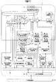
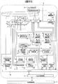
- FIG. 1 is a block diagram showing a hologram recording / reproducing apparatus of Example 1.
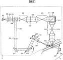
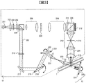
- FIG. It is a figure explaining the recording principle of a hologram recording / reproducing apparatus. It is a figure explaining the reproduction
- FIG. 3 is a diagram illustrating a first incident angle control circuit 21 in Embodiment 1.
- FIG. 3 is a diagram illustrating a first incident angle control circuit 21 in Embodiment 1.
- FIG. 1 is a diagram illustrating a hologram recording medium in Example 1.
- FIG. FIG. 6 is a diagram for explaining a fixed position of each sensor in the first embodiment.
- FIG. 3 is a block diagram illustrating a configuration of a spindle control circuit according to the first embodiment. 3 is a block diagram illustrating a configuration of a radial direction conveyance control circuit in Embodiment 1.
- FIG. 3 is a block diagram illustrating configurations of an eccentricity compensation circuit and a moving stage driving circuit in the first embodiment. It is a figure for demonstrating the case where the fixed position of a 1st eccentricity detection sensor is changed.
- FIG. It is a figure for demonstrating the output signal of the 1st eccentricity detection sensor at the time of changing the fixed position of a 1st eccentricity detection sensor. It is a figure for demonstrating the case where the control method of Example 1 is not used. It is a figure for demonstrating the subject when not using the control method of Example 1.
- FIG. It is a data processing flow at the time of recording. It is a data processing flow at the time of reproduction. It is a block diagram of the signal generation circuit in a hologram recording / reproducing apparatus. It is a block diagram of the signal processing circuit in a hologram recording / reproducing apparatus. It is a figure for demonstrating the case where eccentricity does not exist. It is a figure for demonstrating the case where eccentricity exists.
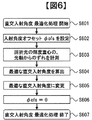
- FIG. 10 is a flowchart of orthogonal incidence angle optimization processing in the second embodiment.
- FIG. 10 is a diagram illustrating a method for calculating an optimum orthogonal incident angle in the second embodiment.
- 12 is a flowchart of seek processing in the third embodiment.
- 10 is a flowchart of orthogonal incident angle optimization processing in Embodiment 3.
- 6 is a block diagram showing a hologram recording / reproducing apparatus in Example 4.
- FIG. 1 is a block diagram showing a recording / reproducing apparatus for a hologram recording medium that records and / or reproduces digital information using holography.
- the hologram recording / reproducing device 10 is connected to an external control device 91 via an input / output control circuit 90.
- the hologram recording / reproducing apparatus 10 receives an information signal to be recorded from the external control device 91 by the input / output control circuit 90.
- the hologram recording / reproducing device 10 transmits the reproduced information signal to the external control device 91 by the input / output control circuit 90.
- the hologram recording medium 1 in the present embodiment has a disk shape. Furthermore, the hologram recording medium 1 in the present embodiment has two types of marks having a predetermined pattern. One is an angle detection mark, which is a mark for detecting the rotation angle of the hologram recording medium. The other is an eccentricity detection mark, which is a mark for detecting the position of the hologram recording medium 1. Details of these marks will be described later.
- the hologram recording / reproducing apparatus 10 includes a pickup 11, a reproducing reference light optical system 12, a cure optical system 13, a rotation angle detection sensor 14, a first eccentricity detection sensor 15, a second eccentricity detection sensor 16, and a radial position detection.
- the sensor 17, the spindle motor 50, the moving stage 51, and the radial direction conveyance unit 52 are provided.
- the spindle motor 50 has a medium attaching / detaching portion (not shown) that allows the hologram recording medium 1 to be attached to and detached from the rotation axis.
- the hologram recording medium 1 is configured to be rotatable by the spindle motor 50.
- the hologram recording medium 1 is configured to be movable in the radial direction by the radial transport unit 52 with reference to the position of the pickup 11.
- the moving stage 51, the rotation angle detection sensor 14, the first eccentricity detection sensor 15, and the second eccentricity detection sensor 16 are all fixed to the movable part of the radial direction conveyance part 52. Further, the spindle motor 50 is fixed to the movable part of the moving stage 51.
- the radial transport unit 52 that can be driven in the radial direction is mounted on a predetermined base member (not shown) to which the pickup 11 is fixed.
- the movable stage 51, the first eccentricity detection sensor 15, the second eccentricity detection sensor 16, and the rotation angle detection sensor 14 are fixed on the movable part of the radial direction conveyance unit 52.
- a spindle motor 50 is fixed on the movable part of the moving stage 51.
- the hologram recording medium 1 having a predetermined mark can be fixed to the rotation shaft of the spindle motor 50.
- the moving stage 51 in this embodiment is a movable stage with two orthogonal axes, and is movable in a plane substantially parallel to the recording surface of the hologram recording medium 1.
- one movable shaft is taken in the same direction as the transport direction of the radial transport unit 52 as the Y axis, and the other movable shaft orthogonal thereto is defined as the X axis.
- the position where the signal light and / or reference light is irradiated is determined by the position of the pickup 11 described later, and is a position fixed to the apparatus.
- the spindle motor 50, the movable part of the radial conveyance part 52, and the moving stage 51 function as means for changing the position on the hologram recording medium 1 to which the signal light and / or the reference light is irradiated.
- the rotation angle detection sensor 14 detects the rotation angle of the hologram recording medium 1 using an angle detection mark provided on the hologram recording medium 1.
- the output signal of the rotation angle detection sensor 14 is input to the spindle control circuit 42.
- the spindle control circuit 42 When changing the rotation angle irradiated with the signal light and the reference light, the spindle control circuit 42 generates a drive signal based on the output signal of the rotation angle detection sensor 14 and the command signal from the controller 80, and the spindle drive circuit
- the spindle motor 50 is driven via 43. Thereby, the rotation angle of the hologram recording medium 1 can be controlled.
- the scale 18 having a predetermined pattern is fixed to the movable part of the radial direction transport part 52.
- the radial position detection sensor 17 detects the position of the movable part of the radial direction transport part 52 using the scale 18.
- the radial direction transport control circuit 44 When the radial position irradiated with the signal light and the reference light is changed, the radial direction transport control circuit 44 generates a drive signal based on the output signal of the radial position detection sensor 17 and the command signal from the controller 80, and the radial direction
- the radial conveyance unit 52 is driven via the conveyance drive circuit 45. Thereby, the hologram recording medium 1 is conveyed in the radial direction. Thereby, the radial position irradiated with the signal light and the reference light can be controlled.
- the first eccentricity detection sensor 15 and the second eccentricity detection sensor 16 detect the position of the hologram recording medium 1 using the eccentricity detection mark provided on the hologram recording medium 1. Output signals from the first eccentricity detection sensor 15 and the second eccentricity detection sensor 16 are input to the eccentricity compensation circuit 40.
- the eccentricity compensation circuit 40 generates a drive signal for compensating for the eccentricity, and drives the moving stage 51 via the moving stage drive circuit 41.
- the details of the first eccentricity detection sensor 15, the second eccentricity detection sensor 16, and the eccentricity compensation circuit 40 will be described later.
- the hologram recording / reproducing apparatus 10 of this embodiment uses the eccentricity detection mark. It operates so that the hologram recording medium 1 is positioned as a reference.
- the pickup 11 plays a role of irradiating the hologram recording medium 1 with reference light and signal light and recording digital information on the recording medium using holography.
- the information signal to be recorded is sent by the controller 80 to a spatial light modulator (described later) in the pickup 11 via the signal generation circuit 81, and the signal light is modulated by the spatial light modulator.
- the reproduction reference light optical system 12 When reproducing the information recorded on the hologram recording medium 1, the reproduction reference light optical system 12 generates a light wave that causes the reference light emitted from the pickup 11 to enter the hologram recording medium 1 in the direction opposite to that during recording. To do. Diffracted light reproduced by the reproduction reference light is detected by a photodetector 226 described later in the pickup 11, and a signal is reproduced by a signal processing circuit 82.
- the diffracted light intensity measurement circuit 83 measures the light intensity of the diffracted light reproduced by the reproduction reference light.
- the diffracted light intensity measuring circuit 83 can measure the intensity of diffracted light as luminance based on the signal from the photodetector 226, and can measure the luminance center of gravity of the diffracted light received by the photodetector 226. It is. In this specification, the luminance detected by the photodetector 226 can be read as the intensity of diffracted light.
- the angle at which the reference light enters the hologram recording medium 1 is controlled by the first incident angle control circuit 21, the second incident angle control circuit 24, and the orthogonal incident angle control circuit 29.
- incident angle and “orthogonal incident angle” are defined in this specification with respect to the angle at which the reference light is incident on the hologram recording medium 1.
- orthogonal incident angle are defined in this specification with respect to the angle at which the reference light is incident on the hologram recording medium 1.
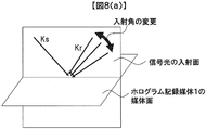
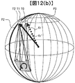
- FIG. 8A shows the wave number vector Ks of the signal light, the wave number vector Kr of the reference light, and the medium surface of the hologram recording medium 1 during recording.
- the incident surface of the signal light is defined as a plane including the wave vector Ks of the signal light and the normal vector of the hologram recording medium 1.
- FIG. 8A shows the state.
- the angle of the wave number vector Kr of the reference light can be changed in the incident surface of the signal light. This change in the angle of the reference light on the incident surface is referred to as “change in the incident angle” in this specification.
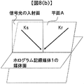
- FIG. 8B and FIG. 8C are diagrams for explaining it.
- FIG. 8B shows a state in which the orthogonal incident angle is changed from the state of FIG.
- FIG. 8C shows a state of FIG. 8B viewed from the side.
- the wave number vector Kr of the reference light is not on the incident surface of the signal light but on the plane A of FIG. 8B. That is, “changing the orthogonal angle” means changing the angle at which the reference light is incident on the hologram recording medium 1 in a direction perpendicular to the incident surface of the signal light.
- the direction in which the incident angle is changed (that is, the direction included in the plane A) and the direction in which the orthogonal incident angle is changed (the direction of the arrow in FIG. 8C) are Must be orthogonal.
- the controller 80 outputs a command value Tgt ⁇ of the incident angle of the reference light to be controlled and a command value Tgt ⁇ of the orthogonal incident angle.
- the incident angle offset output circuit 26 outputs a predetermined value ⁇ ofs in accordance with an instruction from the controller 80.
- the incident angle offset adder 27 adds the command value Tgt ⁇ of the incident angle from the controller 80 and the value ⁇ ofs output from the incident angle offset output circuit 26.
- the first incident angle signal generation circuit 20 generates a signal used for controlling the incident angle of the reference light from the output signal of the pickup 11.
- the first incident angle control circuit 21 generates a drive signal using the output signal of the first incident angle signal generation circuit 20 and the output signal of the incident angle offset adder 27.
- the drive signal output from the first incident angle control circuit 21 is supplied to an actuator 221 described later in the pickup 11 via the first incident angle drive circuit 22.
- the output signal of the first incident angle signal generation circuit 20 is a signal indicating the incident angle of the reference light reflected from the galvanometer mirror 220, and the incident angle is Det ⁇ .
- the incident angle offset adder 27 the command value Tgt ⁇ and the incident angle offset ⁇ ofs are added.
- the first incident angle control circuit 21 has two inputs. The first input is the detected reference beam incident angle Det ⁇ , and the second input is the output signal of the incident angle offset adder 27. The first incident angle control circuit 21 generates the drive signal so that the value of the first input matches the value of the second input.
- the incident angle offset output circuit 26 can finely adjust the incident angle of the reference light.
- the second incident angle signal generation circuit 23 generates a signal used for controlling the incident angle of the reference light from the output signal of the reproduction reference light optical system 12.
- the second incident angle control circuit 24 generates a drive signal using the output signal of the second incident angle signal generation circuit 23 and the output signal of the incident angle offset adder 27.
- the drive signal output from the second incident angle control circuit 24 is supplied to an actuator 224 (described later) in the reproduction reference light optical system 12 via the second incident angle drive circuit 25.
- the orthogonal incident angle signal generation circuit 28 generates a signal to be used for controlling the orthogonal incident angle of the reference light from the output signal of the pickup 11.
- the orthogonal incident angle control circuit 29 generates a drive signal using the output signal of the orthogonal incident angle signal generation circuit 28 and the command value Tgt ⁇ of the orthogonal incident angle from the controller 80.
- the drive signal output from the orthogonal incident angle control circuit 29 is supplied to an actuator 219 described later in the pickup 11 via the orthogonal incident angle drive circuit 30. By driving the actuator 219 in this way, the orthogonal incident angle of the reference light incident on the hologram recording medium 1 is controlled.
- the operations of the second incident angle control circuit 24 and the orthogonal incident angle control circuit 29 are the same as those of the first incident angle control circuit 21 described with reference to FIG.
- the reference light passes through the same plane as the signal light incident surface, The state shown in FIG.
- the angle instructed by the controller 80 to the orthogonal incident angle control circuit 29 is other than the reference position, the reference light is inclined in a direction orthogonal to the incident surface of the signal light. As an example, FIG. ).
- the irradiation time of the reference light and the signal light irradiated on the hologram recording medium 1 can be adjusted by controlling the opening / closing time of the shutter in the pickup 11 via the shutter control circuit 84 by the controller 80.
- the cure optical system 13 plays a role of generating a light beam used for pre-cure and post-cure of the hologram recording medium 1.
- Pre-curing is a pre-process for irradiating a predetermined light beam in advance before irradiating the reference light and signal light to the desired position when recording information at the desired position in the hologram recording medium 1.
- Post-cure is a post-process for irradiating a predetermined light beam after recording information at a desired position in the hologram recording medium 1 so that additional recording cannot be performed at the desired position.
- the light beam used for pre-cure and post-cure is preferably incoherent light, that is, light with low coherence.
- a predetermined light source driving current is supplied from the light source driving circuit 83 to the light sources in the pickup 11 and the cure optical system 13, and each light source can emit a light beam with a predetermined light quantity.
- the pickup 11 and the cure optical system 13 may be simplified by combining several optical system configurations or all optical system configurations into one. Further, regarding the rotation angle detection sensor 14, the first eccentricity detection sensor 15, and the second eccentricity detection sensor 16, some or all of these sensors are integrated to form a single sensor. It doesn't matter.
- FIG. 2 shows a recording principle in an example of a basic optical system configuration of the pickup 11 and the reproducing reference light optical system 12 in the hologram recording / reproducing apparatus 10.
- the reproduction reference light optical system 12 includes an actuator 224 and a galvanometer mirror 225.
- the light beam emitted from the light source 201 passes through the collimator lens 202 and enters the shutter 203.
- the optical element 204 composed of, for example, a half-wave plate or the like, adjusts the light quantity ratio of p-polarized light and s-polarized light to a desired ratio.
- the light beam enters a PBS (Polarization Beam Splitter) prism 205.
- the light beam that has passed through the PBS prism 205 functions as signal light 206, and after the light beam diameter is expanded by the beam expander 208, the light beam passes through the phase mask 209, the relay lens 210, and the PBS prism 211 and passes through the spatial light modulator 212. Is incident on.
- the signal light to which information is added by the spatial light modulator 212 reflects the PBS prism 211 and propagates through the relay lens 213 and the spatial filter 214. Thereafter, the signal light is condensed on the hologram recording medium 1 by the objective lens 215.
- the light beam reflected from the PBS prism 205 works as reference light 207, and is set to a predetermined polarization direction according to recording or reproduction by the polarization direction conversion element 216, and then passes through the mirror 217 and the galvanometer mirror 218. Incident on the galvanometer mirror 220.
- the galvanometer mirror 220 can adjust the angle in the paper surface by the actuator 221, and can set the incident angle of the reference light incident on the hologram recording medium 1 after passing through the lens 222 and the lens 223 to a desired angle.
- an element that converts the wavefront of the reference light may be used instead of the galvanometer mirror.
- the galvanometer mirror 218 can adjust the angle in the direction perpendicular to the paper surface by the actuator 219, and sets the orthogonal incident angle of the reference light incident on the hologram recording medium 1 after passing through the lens 222 and the lens 223 to a desired angle. Can do.
- the signal light and the reference light are incident on the hologram recording medium 1 so as to overlap each other, whereby an interference fringe pattern is formed in the recording medium, and information is recorded by writing this pattern on the recording medium.
- the incident angle of the reference light incident on the hologram recording medium 1 can be changed by the galvanometer mirror 220, recording by angle multiplexing is possible.
- holograms corresponding to each incident angle are called pages, and a set of pages angle-multiplexed in the same area is called a book. To do.
- FIG. 3 shows a reproduction principle in an example of a basic optical system configuration of the pickup 11 and the reproduction reference light optical system 12 in the hologram recording / reproduction apparatus 10.
- the reference beam is incident on the hologram recording medium 1 as described above, and the light beam transmitted through the hologram recording medium 1 is reflected by the galvanometer mirror 225 whose angle can be adjusted by the actuator 224.
- the reference light for reproduction is generated.
- the diffracted light reproduced by the reproduction reference light propagates through the objective lens 215, the relay lens 213, and the spatial filter 214. Thereafter, the diffracted light passes through the PBS prism 211 and enters the photodetector 226, and the recorded signal can be reproduced.
- an image sensor such as a CMOS image sensor or a CCD image sensor can be used as the photodetector 226.
- any element may be used as long as page data can be reproduced.
- the first incident angle signal generation circuit 20 receives an output signal of an angle detection sensor (not shown) provided in the actuator 221 as an input, and indicates the incident angle of the reference light reflected from the galvanometer mirror 220. Is generated as a signal for use in controlling the incident angle.
- the second incident angle signal generation circuit 23 receives the output signal of an angle detection sensor (not shown) provided in the actuator 224 as an input, and the reference light reflected from the galvanometer mirror 225. Is generated as a signal to be used for controlling the incident angle.
- the orthogonal incident angle signal generation circuit 28 receives an output signal of an angle detection sensor (not shown) provided in the actuator 219 as an input, generates a signal indicating the orthogonal incident angle of the reference light reflected from the galvanometer mirror 220, and generates an orthogonal incident angle. It is generated as a signal for use in control.
- an optical encoder can be used as the angle detection sensor provided in the actuator 221, the actuator 224, and the actuator 219.
- the recording technique using the principle of angle multiplexing of holography tends to have a very small tolerance for deviation of the incident angle of the reference beam. Therefore, without using the angle detection sensor provided in the actuator 221, a mechanism for detecting the shift amount of the incident angle of the reference light is provided in the pickup 11, and the first incident angle signal generation circuit 20 is provided with the mechanism.
- the output signal may be used as an input to generate a signal for use in controlling the incident angle of the reference light. The same applies to the second incident angle signal generation circuit 23 and the orthogonal incident angle signal generation circuit 28.
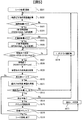
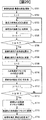
- FIG. 4 shows a flowchart of recording and reproduction in the hologram recording / reproducing apparatus 10.
- processing relating to recording / reproduction using holography in particular will be described.
- a process from when the hologram recording medium 1 is inserted into the hologram recording / reproducing apparatus 10 until preparation for recording or reproduction is completed is referred to as a setup process.
- the process of recording information on the hologram recording medium 1 from the ready state is called a recording process
- the process of reproducing information recorded on the hologram recording medium 1 from the ready state is called a playback process.
- FIG. 4 (a) shows a flowchart of the setup process
- FIG. 4 (b) shows a flowchart of the recording process
- FIG. 4 (c) shows a flowchart of the reproduction process.
- the hologram recording / reproducing apparatus 10 determines whether the inserted medium is a medium for recording or reproducing digital information using holography, for example.
- the medium is determined (step S402).
- the hologram recording / reproducing apparatus 10 reads control data provided on the hologram recording medium 1 (step S403). ), For example, information relating to the hologram recording medium 1 and information relating to various setting conditions during recording and reproduction, for example.
- step S404 After reading the control data, various adjustments according to the control data and learning processing related to the pickup 11 (step S404) are performed. Thereby, the hologram recording / reproducing apparatus 10 completes preparation for recording or reproduction, and ends the setup process (step S405).
- step S404 includes a process for turning on eccentricity compensation control, which will be described later, and thereafter, the eccentricity compensation control is always turned on.
- the hologram recording / reproducing apparatus 10 receives the recording data (step S412), and sends two-dimensional data corresponding to the data to the spatial light modulator 212 in the pickup 11.
- various recording learning processes such as optimization of the power of the light source 201 and optimization of exposure time by the shutter 203 are performed in advance so that high-quality information can be recorded on the hologram recording medium 1 (steps). S413).
- the spindle motor 50, the radial transport unit 52, and the moving stage 51 are controlled using the spindle control circuit 42, the radial transport control circuit 44, and the eccentricity compensation circuit 40.
- the hologram recording medium 1 is positioned so that the light beam irradiated from the pickup 11 and the cure optical system 13 is irradiated to a predetermined position of the hologram recording medium 1.
- the address information is reproduced to check whether the hologram recording medium 1 is positioned at the target position. If the hologram recording medium 1 is not positioned at the target position, the deviation amount from the predetermined position is calculated. Then, the positioning operation is repeated.
- a flowchart of the seek operation in this embodiment will be described later.
- step S415 a data recording process for recording data to be recorded as a hologram on the hologram recording medium 1 is performed. Details of the data recording process will be described later.
- the recording process is terminated (step S416). Note that data may be verified as necessary.
- the hologram recording / reproducing apparatus 10 first performs a seek operation (step S422) by using the spindle control circuit 42, the radial conveyance control circuit 44, and the eccentricity compensation circuit 40, and the pickup 11 and the reproduction.
- the hologram recording medium 1 is positioned so that the light beam irradiated from the reference light optical system 12 is irradiated to a predetermined position of the hologram recording medium 1.
- the address information is reproduced to check whether the hologram recording medium 1 is positioned at the target position. If the hologram recording medium 1 is not positioned at the target position, the deviation amount from the predetermined position is calculated. Then, the positioning operation is repeated.
- step S423 information recorded on the hologram recording medium 1 is read from the two-dimensional data detected by the photodetector 226 (step S423), and reproduction data is transmitted (step S424).
- reproduction data is transmitted (step S425).
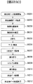
- FIG. 22 shows a data processing flow during recording and reproduction.
- FIG. 22A shows the two-dimensional data on the spatial light modulator 212 after the recording data receiving process S412 in the input / output control circuit 90.
- FIG. 22B shows a recording data processing flow in the signal generation circuit 81 until conversion.
- FIG. 22B shows the process up to reproduction data transmission processing S424 in the input / output control circuit 90 after the two-dimensional data is detected by the photodetector 226.
- the reproduction data processing flow in the signal processing circuit 82 is shown.
- step S8101 When data processing at the time of recording is started (step S8101), the signal generation circuit 81 receives recording data (step S8102). Subsequently, the recording data is divided into a plurality of data strings, and each data string is converted to CRC so that an error can be detected during reproduction (step S8103). Subsequently, for the purpose of making the number of on-pixels and the number of off-pixels substantially equal and preventing repetition of the same pattern, scramble is performed to add a pseudo-random number data sequence to the data sequence (step S8104). Thereafter, error correction coding such as Reed-Solomon code is performed so that error correction can be performed during reproduction (step S8105).
- error correction coding such as Reed-Solomon code
- this data string is converted into M ⁇ N two-dimensional data, and the two-dimensional data for one page is constructed by repeating it for one page data (step S8106).
- a marker serving as a reference in image position detection and image distortion correction during reproduction is added to the two-dimensional data configured as described above (step S8107), and the data is transferred to the spatial light modulator 212 (step S8108).
- the data processing at the time of recording is completed. (Step S8109).
- step S8201 When data processing at the time of reproduction is started (step S8201), reproduced image data detected by the photodetector 226 is transferred to the signal processing circuit 82 (step S8202). Subsequently, the image position is detected with reference to the marker included in the image data (step S8203), and distortion such as the tilt, magnification, and distortion of the image is corrected (step S8204). Thereafter, binarization is performed (step S8205), and the marker is removed (step S8206). Subsequently, two-dimensional data for one page is acquired (step S8207).
- step S8208 After converting the two-dimensional data obtained in this way into a plurality of data strings, error correction processing is performed to remove the parity data string (step S8208). Next, scramble is canceled (step S8209), and error detection processing by CRC is performed (step S8210). Finally, the reproduction data generated by deleting the CRC parity is transmitted via the input / output control circuit 90 (step S8211). Thus, the data processing at the time of reproduction is completed (step S8212).
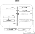
- FIG. 23 is a block diagram of the signal generation circuit 81 of the hologram recording / reproducing apparatus 10.
- the input / output control circuit 90 When input of recording data is started to the input / output control circuit 90, the input / output control circuit 90 notifies the controller 80 that input of recording data has started. Upon receiving this notification, the controller 80 commands the signal generation circuit 81 to record the data for one page input from the input / output control circuit 90. A processing command from the controller 80 is notified to the sub-controller 8101 in the signal generation circuit 81 via the control line 8108. Upon receiving this notification, the sub-controller 8101 controls each signal processing circuit via the control line 8108 so that the signal processing circuits are operated in parallel. First, the memory control circuit 8103 is controlled to store the recording data input from the input / output control circuit 90 via the data line 8109 in the memory 8102.
- the CRC calculation circuit 8104 performs control to convert the recording data to CRC.
- the scramble circuit 8105 scrambles the CRC-converted data to add a pseudo random number data sequence
- the error correction encoding circuit 8106 performs error correction encoding to add the parity data sequence.
- the pickup interface circuit 8107 reads out the error correction encoded data from the memory 8102 in the order of the two-dimensional data on the spatial light modulator 212, adds a reference marker at the time of reproduction, Two-dimensional data is transferred to the spatial light modulator 212.
- FIG. 24 is a block diagram of the signal processing circuit 82 of the hologram recording / reproducing apparatus 10.
- the controller 80 instructs the signal processing circuit 82 to reproduce the data for one page input from the pickup 11.
- a processing command from the controller 80 is notified to the sub-controller 8201 in the signal processing circuit 82 via the control line 8211.
- the sub-controller 8201 controls each signal processing circuit via the control line 8211 so that the signal processing circuits are operated in parallel.
- the memory control circuit 8203 is controlled to store image data input from the pickup 11 via the pickup interface circuit 8210 via the data line 8212 in the memory 8202.
- the image position detection circuit 8209 performs control to detect a marker from the image data stored in the memory 8202 and extract an effective data range.
- the image distortion correction circuit 8208 performs distortion correction such as image inclination, magnification, and distortion using the detected marker, and controls to convert the image data into the expected two-dimensional data size.
- Each bit data of a plurality of bits constituting the size-converted two-dimensional data is binarized by determining “0” or “1” in the binarization circuit 8207, and the data is arranged on the memory 8202 in the order of the output of the reproduction data Control to store.
- the error correction circuit 8206 corrects an error included in each data string, and the scramble release circuit 8205 cancels the scramble to add the pseudo-random number data string. Check not included. Thereafter, the reproduction data is transferred from the memory 8202 to the input / output control circuit 90.
- FIG. 13 shows the hologram recording medium 1, in which a circle R1 indicates the innermost circumference of the medium and a circle R2 indicates the outermost circumference of the medium.
- a point O in FIG. 13 indicates the geometric center of the hologram recording medium 1.
- the variable r is a variable indicating the radius measured from the point O.
- a mark is provided in the hologram recording medium 1 .
- a region where user data is recorded as a hologram is r5 ⁇ r ⁇ r6. That is, the marks M1 and M2 are provided on the inner peripheral side with respect to an area where user data is recorded as a hologram.
- the mark M1 is an angle detection mark
- the mark M2 is an eccentricity detection mark.
- FIG. 14 is a diagram for explaining a fixed position of each sensor when the movable part of the radial direction conveyance part 52 is used as a reference.
- the point xy0 indicates the drive reference position of the moving stage 51.
- the movable stage 51 moves 0.5 mm in the plus direction from the minus movable end with respect to the X axis, and the plus direction from the minus movable end in the Y axis
- the point moved by 0.5 mm is the point xy0. That is, when the movable part of the moving stage 51 is at the drive reference position xy0, the rotation shaft of the spindle motor 50 is positioned directly above xy0.
- a point P14 indicates the sensor center of the rotation angle detection sensor 14.
- the point P15 indicates the sensor center of the first eccentricity detection sensor 15
- the point P16 indicates the sensor center of the second eccentricity detection sensor 16.
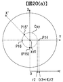
- P15 and P16 exist on a circle Cxy having a radius r2 centered on the point xy0.
- the “sensor center” indicates the center position of the light spot irradiated by the sensor.
- arranging the rotation angle detection sensor 14 so that the center position of the light spot irradiated by the rotation angle detection sensor 14 coincides with the point P14 is expressed as “disposing the rotation angle detection sensor 14 at the point P14”. To do.
- the rotation angle detection sensor 14 is provided in the region of r3 ⁇ r ⁇ r4. It is located at the center of the angle detection mark M1.
- the first eccentricity detection sensor 15 and the second eccentricity detection sensor 16 have r1 ⁇ r ⁇ . It is located at the outer peripheral edge of the eccentricity detection mark M2 provided in the region r2.
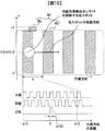
- FIG. 15 is a schematic diagram of the angle detection mark M1 and a signal output from the rotation angle detection sensor 14.
- the angle detection mark M1 includes a mark Mp in which the reflection part and the non-reflection part are repeated at a predetermined period p, and a mark Mz provided only once per rotation of the medium.
- the mark Mz is a mark for generating a Z-phase signal described later
- the mark Mp is a mark for generating an A-phase signal and a B-phase signal described later.
- detection light having a predetermined wavelength is emitted from the rotation angle detection sensor 14 to generate a light spot on the mark Mp.
- the rotation angle detection sensor 14 detects the rotation angle by detecting the light reflected by the mark Mp.
- three types of signals as shown in the figure are obtained as output signals of the rotation angle detection sensor 14.
- the A phase signal and the B phase signal are rectangular waves in which 8 periods are output while moving the period p of the mark Mp.
- the phase of the A-phase signal and that of the B-phase signal differ by 90 degrees, and the magnitude of the phase changes depending on the moving direction of the light spot irradiated on the mark Mp.
- the B phase signal has an output whose phase is advanced by 90 degrees with respect to the A phase signal.
- the B-phase signal has an output delayed by 90 degrees with respect to the A-phase signal.
- the Z-phase signal is generated from a light spot (not shown) irradiated on the mark Mz, and a pulse having the same width as the A-phase signal is output only once when the medium is rotated once.
- the A-phase signal, B-phase signal, and Z-phase signal are in the form of a general output as an output signal of the incremental encoder.
- the rotation angle of the medium can be obtained from these three signals.
- the current angle is calculated by determining an angle that is 0 degrees based on the Z-phase signal and accumulating the rotation angle from the A-phase signal and the B-phase signal. Since the phase difference between the A phase signal and the B phase signal is 90 degrees, the minimum resolution of the rotation angle detection sensor 14 of this embodiment is an amount corresponding to 1 ⁇ 4 of the period of the A phase signal, and the mark Mp It becomes p / 32 in the upper distance conversion. In order to convert the distance on the mark Mp into the rotation angle, since the arc and radius of the sector are known, the center angle of the arc may be obtained by calculation.
- the configuration of the rotation angle detection sensor 14 is illustrated in FIG. 15, but the present invention is not limited to this.
- a sensor using the detection principle of an absolute encoder may be used.
- the A-phase signal that is the output signal of the rotation angle detection sensor 14 is a logical signal (rectangular wave), but an analog signal (for example, a sine wave) that can obtain information corresponding to the angle is output. It may be a sensor.
- the configuration of the incremental encoder shown in FIG. 15 becomes a rotary encoder when the marks Mp are arranged in a circle, but becomes a line encoder when arranged in a straight line. That is, this method can be used not only as a rotation angle but also as a sensor for measuring displacement in one direction.
- the radial position detection sensor 17 in this embodiment is an incremental line encoder. That is, in the above description, the rotation angle detection sensor 14 is replaced with the radial position detection sensor 17, and the angle detection mark M 1 provided on the hologram recording medium 1 is fixed to the movable portion of the radial conveyance unit 52. What is necessary is just to replace with the predetermined pattern of the scale 18. Similarly, the A-phase signal, the B-phase signal, and the Z-phase signal are output from the radial position detection sensor 17.
- the first eccentricity detection sensor 15 and the second eccentricity detection sensor 16 are of the same type as the sensors except for the attachment positions. Therefore, the first eccentricity detection sensor 15 will be described below.
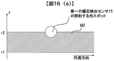
- FIG. 16A is a schematic diagram of the eccentricity detection mark M2.
- the eccentricity detection mark M2 is deposited with a metal film over the region of r1 ⁇ r ⁇ r2, and functions as a reflecting portion. That is, the shaded portion in the figure is a reflection portion, and the other portion is a non-reflection portion.
- the first eccentricity detection sensor 15 is irradiated with detection light having a predetermined wavelength, and a light spot is generated on the mark M2. The first eccentricity detection sensor 15 detects the light reflected by the mark M2.
- the sensor center of the first eccentricity detection sensor 15 is fixed at a radius r2. Therefore, when the movable part of the moving stage 51 is at the drive reference position xy0 and the hologram recording medium 1 has no eccentricity, the first eccentricity detection sensor 15 irradiates as shown in FIG. The light spot is located at the outer peripheral edge of the eccentricity detection mark M2 provided in the region of r1 ⁇ r ⁇ r2.
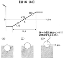
- FIG. 16B is a diagram for explaining an output signal of the first eccentricity detection sensor 15.
- the output signal from the first eccentricity detection sensor 15 is one, and a voltage corresponding to the relative positional relationship between the light spot generated by the detection light and the eccentricity detection mark M2 is output.
- the light spot irradiated by the eccentricity detection sensor 15 and the outer peripheral edge of the eccentricity detection mark M2 can be displaced in the radial direction.
- a difference between the relative positions in the radial direction between the light spot irradiated by the first eccentricity detection sensor 15 and the outer peripheral edge of the eccentricity detection mark M2 is represented by ⁇ rs.
- the relationship between the radial relative position difference ⁇ rs and the output voltage Vs from the first eccentricity detection sensor 15 is as shown in FIG. That is, during the predetermined detection range rs_v, the output voltage Vs becomes a voltage proportional to the difference ⁇ rs in the relative position between the first eccentricity detection sensor 15 and the eccentricity detection mark M2 in the radial direction. Further, when the output voltage Vs becomes zero, the light spot irradiated by the first eccentricity detection sensor 15 is located at the outer peripheral edge of the eccentricity detection mark M2. As for the first eccentricity detection sensor 15, the direction of taking ⁇ rs is the negative direction of the X axis.
- the first eccentricity detection sensor 15 is arranged on the X axis in the orthogonal coordinate axis with the drive reference position xy0 as the origin.
- the second eccentricity detection sensor 16 is arranged on the Y axis in the orthogonal coordinate axis with the drive reference position xy0 as the origin.
- the position of the eccentricity detection mark M2 can be detected by arranging the sensors capable of detecting the relative position with the eccentricity detection mark M2 orthogonally. Further, if the moving stage 51 can be controlled so that the output voltages of both sensors become zero, the edge of the eccentricity detection mark M2 is positioned directly above both sensors (that is, both sensors irradiate). The position of the hologram recording medium 1 can be controlled so that the center of the light spot is located at the edge of the eccentricity detection mark M2.
- the rotation angle detection sensor 14, the first eccentricity detection sensor 15, and the second eccentricity detection sensor 16 all irradiate the hologram recording medium 1 with a light spot as detection light for detecting a mark.
- the wavelength of the light is preferably different from the wavelength of the reference light. Since the wavelength of the signal light and the wavelength of the reference light are the same, they may be expressed as different from the wavelength of the signal light. This is because it is known that when light having a wavelength close to that of the reference light is irradiated onto an unrecorded hologram recording medium, the reproduction quality is deteriorated when a hologram is subsequently recorded at the irradiation position. is there.
- the detection light can be, for example, light having a wavelength of 650 nm that differs from the wavelength of the reference light by 100 nm or more.
- the configuration of the spindle control circuit 42 of this embodiment will be described with reference to FIG.
- the spindle control circuit 42 includes a rotation angle calculation circuit 4201, a spindle controller 4202, a spindle output control switch 4203, and a spindle control determination circuit 4204.
- the spindle control circuit 42 controls the spindle motor 50 so that the rotation angle of the hologram recording medium 1 becomes the angle command value Tgt ⁇ from the controller 80.
- This control is referred to as spindle control in this specification.
- the rotation angle calculation circuit 4201 receives the A-phase signal, the B-phase signal, and the Z-phase signal output from the rotation angle detection sensor 14, calculates the rotation angle Det ⁇ of the current hologram recording medium 1 from the three signals, and calculates Det ⁇ . Output as a signal.
- the spindle controller 4202 receives the Det ⁇ signal and the angle command Tgt ⁇ signal from the controller 80, and outputs a drive signal for controlling the spindle motor 50.
- the spindle output control switch 4203 receives the output signal of the spindle controller 4202, and controls whether to output the output signal of the spindle controller 4202 according to the control signal SPON from the controller 80.
- the spindle output control switch 4203 selects the terminal a and outputs the output signal of the spindle controller 4202 as an SPD signal.
- the spindle output control switch 4203 selects the terminal b, outputs the reference potential as the SPD signal, and does not output the output signal of the spindle controller 4202.
- the SPON signal is a signal for instructing on / off of spindle control.
- the spindle output control switch 4203 functions as a switch for turning on / off spindle control.
- the SPD signal output from the spindle output control switch 4203 is amplified by the spindle drive circuit 43, and the spindle motor 50 is controlled.
- the spindle control determination circuit 4204 receives the Det ⁇ signal and the Tgt ⁇ signal, determines whether the rotation angle of the hologram recording medium 1 is a value near the angle command value Tgt ⁇ , and outputs it as a SPOK signal. When the rotation angle of the hologram recording medium 1 is a value in the vicinity of the angle command value Tgt ⁇ , the SPOK signal is assumed to be High. For example, the spindle control determination circuit 4204 measures an elapsed time after the difference between the current angle Det ⁇ detected by the rotation angle detection sensor 14 and the angle command value Tgt ⁇ is equal to or less than a predetermined threshold, and the measurement time is a predetermined time. This can be realized by making a circuit that performs the determination by continuing as described above.
- the SPOK signal that is the determination result is input to the controller 80. Therefore, the controller 80 can determine whether or not the rotation angle of the hologram recording medium 1 is a value near the angle command value Tgt ⁇ based on the SPOK signal. That is, the spindle control determination circuit 4204 functions as a circuit that determines the convergence of the spindle control.
- the configuration of the radial direction conveyance control circuit 44 in this embodiment will be described with reference to FIG.
- the radial direction conveyance control circuit 44 includes a radial position calculation circuit 4401, a radial position controller 4402, a radial position output control switch 4403, and a radial position control determination circuit 4404.
- the radial direction transport control circuit 44 controls the radial direction transport unit 52 so that the position of the movable part of the radial direction transport unit 52 becomes the position command value TgtR from the controller 80.
- This control is referred to as radial position control in this specification.
- the configuration of the radial conveyance control circuit 44 is similar to the configuration of the spindle control circuit 42.
- the radial position calculation circuit 4401 receives the A-phase signal, the B-phase signal and the Z-phase signal output from the radial position detection sensor 17 and calculates the current radial position DetR of the hologram recording medium 1 from the above three signals. Output as a signal.
- the radial position controller 4402 receives the DetR signal and the radial position command TgtR signal from the controller 80, and outputs a drive signal for controlling the radial transport unit 52.
- the radial position output control switch 4403 receives the output signal of the radial position controller 4402 and controls whether to output the output signal of the radial position controller 4402 according to the control signal RDON from the controller 80.
- the radial position output control switch 4403 selects the terminal c and outputs the output signal of the radial position controller 4402 as the RDD signal.
- the radial position output control switch 4403 selects the terminal d, outputs the reference potential as the RDD signal, and does not output the output signal of the radial position controller 4402.
- the RDON signal is a signal for instructing on / off of the radial position control.
- the radial position output control switch 4403 functions as a switch for switching on / off the radial position control.
- the RDD signal output from the radial position output control switch 4403 is amplified by the radial conveyance drive circuit 45, and the radial conveyance unit 52 is controlled.
- the radial position control determination circuit 4404 receives the DetR signal and the TgtR signal, determines whether the radial position of the hologram recording medium 1 is a value near the radial position command value TgtR, and outputs it as an RDOK signal. Note that when the radius position of the hologram recording medium 1 is a value in the vicinity of the radius position command value TgtR, the RDOK signal is assumed to be High.
- the radial position control determination circuit 4404 measures, for example, an elapsed time after the difference between the current radial position DetR detected by the radial position detection sensor 17 and the radial position command value TgtR is equal to or less than a predetermined threshold, and the measurement is performed.
- the radial position control determination circuit 4404 functions as a circuit that determines the convergence of the radial position control.
- the spindle control determination circuit 4204 in the present embodiment measures the elapsed time after the difference between the current angle Det ⁇ and the angle command value Tgt ⁇ is equal to or less than a predetermined threshold, and determines that the measurement time continues for a predetermined time or more. It was set as the structure which performs. However, the spindle control determination circuit 4204 may have another configuration as long as it can determine whether the rotation angle of the hologram recording medium 1 is a value near the angle command value Tgt ⁇ . For example, if the current angle Det ⁇ is equal to the angle command value Tgt ⁇ even once, the SPOK signal may be set to High at that time. The same applies to the radial position control determination circuit 4404.
- the configuration of the eccentricity compensation circuit 40 and the moving stage drive circuit 41 in the present embodiment will be described with reference to FIG.
- the eccentricity compensation circuit 40 includes an X-axis compensator 4001, an X-axis output control switch 4002, a Y-axis compensator 4003, a Y-axis output control switch 4004, and an eccentricity compensation determination circuit 4005.
- the moving stage driving circuit 4s1 includes an X-axis driving circuit 4101 and a Y-axis driving circuit 4102. Based on the command signal from the controller 80, the eccentricity compensation circuit 40 controls the moving stage 51 so that the hologram recording medium 1 is positioned with reference to the eccentricity detection mark. This control is referred to as eccentricity compensation control in this specification.
- the output signal of the first eccentricity detection sensor 15 is input to the X-axis compensator 4001, and a drive signal for driving the X-axis of the moving stage 51 is generated.
- the X-axis output control switch 4002 receives the output signal from the X-axis compensator 4001 and controls whether to output the output signal from the X-axis compensator 4001 according to the control signal XYON from the controller 80. When the XYON signal is High, the X-axis output control switch 4002 selects the terminal a and outputs the output signal of the X-axis compensator 4001 as an XD signal.
- the X-axis output control switch 4002 selects the terminal b, outputs the reference potential as the XD signal, and does not output the output signal of the X-axis compensator 4001.
- the XD signal output from the X-axis output control switch 4002 is amplified by the X-axis drive circuit 4101 and the X-axis of the moving stage 51 is controlled.
- the output signal of the second eccentricity detection sensor 16 is input to the Y axis compensator 4003, and a drive signal for driving the Y axis of the moving stage 51 is generated.
- the Y-axis output control switch 4004 receives the output signal of the Y-axis compensator 4003 and controls whether or not to output the output signal of the Y-axis compensator 4003 according to the control signal XYON from the controller 80. When the XYON signal is High, the Y-axis output control switch 4004 selects the terminal a and outputs the output signal of the Y-axis compensator 4003 as a YD signal.
- the Y-axis output control switch 4004 selects the terminal b, outputs the reference potential as the YD signal, and does not output the output signal of the Y-axis compensator 4003.
- the YD signal output from the Y axis output control switch 4004 is amplified by the Y axis drive circuit 4102 and the Y axis of the moving stage 51 is controlled.
- the eccentricity compensation determination circuit 4005 receives the output signal of the first eccentricity detection sensor 15 and the output signal of the second eccentricity detection sensor 16 and positions the hologram recording medium 1 with reference to the eccentricity detection mark. It is determined whether or not it is completed, and is output as an XYOK signal. It should be noted that the XYOK signal becomes High when the positioning of the hologram recording medium 1 with the eccentricity detection mark as a reference is completed. The XYOK signal is input to the controller 80. Therefore, the controller 80 can determine whether or not the positioning of the hologram recording medium 1 with reference to the eccentricity detection mark is completed based on the XYOK signal. That is, the eccentricity compensation determination circuit 4005 functions as a circuit that determines the convergence of the eccentricity compensation control.
- the eccentricity compensation determination circuit 4005 is an attached circuit. Therefore, as can be seen from FIG. 19, the control system related to the eccentricity compensation circuit 40 and the moving stage drive circuit 41 includes a control system related to the X axis indicated by the broken line (A) and a control system related to the Y axis indicated by the broken line (B). being independent. That is, the eccentricity compensation circuit 40 receives the output signal of the first eccentricity detection sensor 15 and the output signal of the second eccentricity detection sensor 16, and is used for controlling the X axis of the moving stage 51. Is only the output signal of the first eccentricity detection sensor 15. Similarly, only the output signal of the second eccentricity detection sensor 16 is used for controlling the Y axis of the moving stage 51.
- the X-axis compensator 4001 performs control so that the voltage of the output signal of the first eccentricity detection sensor 15 that is input becomes zero.
- control is performed so that the voltage of the output signal of the second eccentricity detection sensor 16 that is input becomes zero.
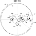
- the case where the hologram recording medium 1 is eccentric is a case where the geometric center of the innermost circle R1 of the medium does not coincide with O, as will be described with reference to FIG. Even in such a case, the moving stage 51 controls the position of the hologram recording medium 1 using the eccentricity detection mark M1. Specifically, the geometric center O of the eccentricity detection mark M1 is controlled so as to coincide with the drive reference position of the moving stage 51.
- the position where the signal light and / or the reference light is irradiated is a position fixed to the apparatus. Therefore, this operation is performed so that the hologram recording medium 1 is positioned with reference to the eccentricity detection mark even when there is an eccentricity. In other words, this can be controlled so that the signal light and / or the reference light is irradiated to the position where the eccentricity is canceled.
- the first eccentricity detection sensor 15 and the second eccentricity detection sensor 16 are arranged orthogonally with respect to the drive reference position xy0, and the orthogonal direction is the direction of the drive axis of the moving stage 51. Identical. Next, the reason for adopting such a configuration will be described.
- the spindle control circuit 42, the radial direction transport control circuit 44, and the eccentricity compensation circuit 40 have the same configuration as described above. That is, the eccentricity compensation circuit 40 is configured to drive the X axis of the moving stage 51 based on the output signal of the first eccentricity detection sensor 15.
- the output signal of the first eccentricity detection sensor 15 when the first eccentricity detection sensor 15 is arranged at the position P15 ' is as shown in FIG. That is, the direction in which ⁇ rs is taken is not the X-axis direction but the X′-axis direction. If the way of taking ⁇ rs is changed in this way, the relationship between ⁇ rs and the output voltage Vs becomes the same as in the case of FIG.
- the control system needs to be independent in the vicinity of the control target point.
- the edge of the eccentricity detection mark M2 is inclined 45 degrees in the vicinity of the point P15 '. For this reason, when the hologram recording medium 1 moves to the left by a minute distance, the output of the first eccentricity detection sensor 15 also varies. As a result, the control by the eccentricity compensation circuit 40 may not converge.
- the first eccentricity detection sensor 15 is arranged at the position P15 as in the configuration of the present embodiment, similarly, consider the situation where the hologram recording medium 1 has moved to the left by a minute distance. In this case, the displacement in the X-axis direction of the edge of the eccentricity detection mark M2 in the vicinity of the point P15 is almost zero because the tangent line of the circle Cxy is parallel to the Y-axis at the point P15. Therefore, in the case of the configuration of the present embodiment, the X axis is hardly driven, and only the Y axis is driven. For this reason, the configuration of the present embodiment does not cause a problem.
- the biaxial control by the moving stage 51 converges to a preferred position without oscillation.
- the first eccentricity detection sensor 15 and the second eccentricity detection sensor 16 are arranged to be orthogonal to the drive reference position xy0.
- the tangents of the circle Cxy at the points P15 and P16 which are points where the eccentricity detection sensors are arranged, are parallel to the drive axis of the moving stage 51. That is.
- the seek process S414 in the present embodiment will be described with reference to the flowchart of FIG. Note that the same flowchart is applied to the seek process S422.
- the radius r and the rotation angle ⁇ are parameters.
- the drive shaft having the radius r is referred to as r-axis
- the drive shaft having the rotation angle ⁇ is referred to as ⁇ -axis.
- the eccentricity compensation control is started by setting the XYON signal to High in the learning process step S404 performed before the seek process S414. Therefore, the eccentricity compensation control is turned on at the time when the seek process S414 is started.
- step S501 When the seek process is started (step S501), the difference between the coordinates (r, ⁇ ) where the hologram of the target address is located and the current position is calculated, and the movement amount is calculated for the r axis and the ⁇ axis (step S502). Next, it is determined whether the movement amount of the r-axis is other than zero (step S503). If the movement amount of the r-axis is other than zero (Yes in step S503), the radial position control is turned on by setting the RDON signal to High, and the command value TgtR is changed to move the r-axis. Start (step S504). After step S504, the process proceeds to step S505 described later. If the r-axis movement amount is zero (No in step S503), the process proceeds to step S505 without performing step S504.
- step S505 it is determined whether the amount of movement of the ⁇ axis is other than zero. If the movement amount of the ⁇ axis is other than zero (Yes in step S505), the spindle control is turned on by changing the SPON signal to High and the command value Tgt ⁇ is changed to start the movement of the ⁇ axis. (Step S506). After step S506, the process proceeds to step S507 described later. If the movement amount of the ⁇ axis is zero (No in step S505), the process proceeds to step S507 without performing step S506.
- step S507 it is determined whether the movement is completed.
- the movement is completed.
- step S507 If it is determined that the movement has not been completed (No in step S507), the process returns to step S507 again. That is, if any one of the RDOK signal, the SPOK signal, and the XYOK signal is at a low level, the operation is not determined that the movement has been completed, but waits until all the above three signals simultaneously become a high level. It becomes.
- both the RDON signal and the SPON signal are set to low to turn off the radial position control and the spindle control and end the movement (step S508).
- the controller 80 outputs the command value Tgt ⁇ of the reference light incident angle, thereby changing the reference light incident angle (step S509).
- the command value Tgt ⁇ output here is an incident angle corresponding to the hologram page to be positioned by seek processing.
- step S510 it is determined whether or not the seek process during reproduction is performed. If the seek is not during playback (No in step S510), the process proceeds to step S518 described later, and the seek process is terminated. If it is a seek at the time of reproduction (in the case of Yes in step S510), the seek process is not completed by this, and finally, the address is obtained by reproducing the recorded hologram, and the target address is correctly positioned. Continue seek processing until This is because a seek at the time of recording results in a seek to an unrecorded portion, and address information cannot be obtained.
- step S5 If it is a seek at the time of reproduction (Yes in step S510), orthogonal incidence angle optimization processing is performed (step S511). Details of the orthogonal incident angle optimization processing will be described later.
- step S511 it is determined whether the amount of diffracted light is larger than the threshold L_th (step S512). If the amount of diffracted light is greater than the threshold value L_th (Yes in step S512), it is determined whether the hologram can be reproduced (step S513).
- step S512 When the amount of diffracted light is smaller than the threshold value L_th (No in step S512) and when the amount of diffracted light is larger than the threshold L_th but the hologram is NG (No in step S513), positioning is accurate. It means that it could not be done. Therefore, the r-axis and ⁇ -axis retry values are calculated based on the predetermined retry parameter (step S514), and the process returns to step S502. As a result, a retry seek to move to the positioned vicinity is performed.
- step S5 the address information included in the reproduced hologram is acquired (step S515). Subsequently, it is determined whether or not the acquired address is a target address (step S516). If the acquired address is not the target address (No in step S516), it means that positioning has not been performed correctly. Therefore, the difference between the coordinates (r, ⁇ ) of the acquired address and the coordinates (r, ⁇ ) of the target address is calculated (step S517), and the process returns to step S502. As a result, a retry seek based on the address information of the hologram is performed.
- step S5136 If the acquired address is the target address (Yes in step S516), the seek process is terminated (step S518).
- the spindle control converges to the vicinity of the angle command value Tgt ⁇ , and the SPOK signal becomes High.
- the spindle control is not turned off unless the XYOK signal output from the eccentricity compensation determination circuit 4005 is High (that is, the output signal of the spindle controller 4202 is continuously output as the SPD signal).
- the SPOK signal functions as a spindle control convergence determination circuit, and when the SPOK signal becomes High, the spindle control is turned off purely. It's okay. However, this is not done in this embodiment. The reason for this will be described later.
- step S601 the controller 80 instructs the incident angle offset output circuit 26 to set the incident angle offset ⁇ ofs to a predetermined value.
- step S508 of FIG. 5 which is a flowchart of the seek process. That is, the incident angle offset output circuit 26 outputs a value other than zero as the incident angle offset ⁇ ofs, so that the incident angle can be controlled to be shifted by ⁇ ofs.
- the diffracted light intensity measurement circuit 83 is used to measure the deviation of the luminance gravity center of the diffracted light from the optical axis (step S603).
- the controller 80 calculates an optimal orthogonal incident angle from the deviation of the luminance center of gravity of the diffracted light (step S604).
- the controller 80 functions as a means for calculating the orthogonal incident angle.
- step S604 the incident angle of the reference light is shifted by a known value ⁇ ofs. If there is a deviation in the orthogonal incident angle while the incident angle of the reference light is deviated, it is observed as a phenomenon in which the luminance center of gravity is deviated in the photodetector 226 in this embodiment. This will be described with reference to FIG.
- FIG. 7 schematically shows the luminance distribution of the photodetector 226 when the incident angle of the reference light is changed.
- 7A to 7C show the luminance distribution of the photodetector 226 when the incident angle of the reference light is changed in a state where the incident angle of the reference light is shifted from the optimum value by ⁇ ofs in the plus direction.
- FIG. 7A shows a case where the orthogonal incident angle of the reference light is deviated from the optimum value in the minus direction.
- FIG. 7B shows a case where the orthogonal incident angle of the reference light is an optimum value
- FIG. 7C shows a case where the orthogonal incident angle of the reference light is deviated from the optimum value in the plus direction.
- the optimum value of the orthogonal incident angle means an orthogonal incident angle at which the intensity of diffracted light is maximized.
- the diffracted light generated from the hologram recording medium 1 propagates to the photodetector 226 through the objective lens 215 and the like along the optical axis shown in FIG. For this reason, the luminance gravity center in the photodetector 226 coincides with the center of the light receiving surface of the photodetector 226.
- the diffracted light generated from the hologram recording medium 1 is shown in FIG.
- the light beam deviates from the optical axis, passes through the objective lens 215, etc., and propagates to the photodetector 226.
- it is observed on the photodetector 226 as a phenomenon in which the luminance is shifted. That is, the phenomenon that the luminance center of gravity in the photodetector 226 is shifted can be rephrased as a phenomenon in which diffracted light propagates out of the optical axis of the optical system.
- the incident angle offset ⁇ ofs in addition to the incident angle of the reference light is known, for example, the deviation of the orthogonal incident angle and the deviation of the luminance centroid in the case of the incident angle offset ⁇ ofs are obtained experimentally. Thereby, the deviation from the optimum value of the orthogonal incident angle can be calculated from the deviation of the luminance center of gravity. By utilizing this fact, the optimum value of the orthogonal incident angle can be calculated.
- step S604 the controller 80 sets the orthogonal incident angle command value Tgt ⁇ of the reference light to the optimum orthogonal incident angle calculated in step S604 (step S605).
- the actuator 219 is driven so that the orthogonal incident angle of the reference light is changed to the value calculated in step S604.
- the orthogonal incident angle of the reference light is changed to the optimum orthogonal incident angle calculated in step S604.
- step S605 the controller 80 instructs the incident angle offset output circuit 26 to set the incident angle offset ⁇ ofs to zero (step S606), and ends the orthogonal incident angle optimization process (step S607).
- step S605 the order of setting the optimal orthogonal incident angle in step S605 and setting zero to the incident angle offset ⁇ ofs in step S606 may be reversed. If the optimum orthogonal incident angle setting in step S605 and the setting of zero to the incident angle offset ⁇ ofs in step S606 are both completed, the information from the hologram is reproduced following the seek process. Good.
- two points are important: “positioning” with respect to the hologram when the hologram recording medium 1 is conveyed, and adjustment with respect to the reference light so that the “diffraction condition” is satisfied after the positioning is completed.
- the hologram recording / reproducing apparatus of the present embodiment has an eccentricity compensation control system in order to solve the eccentricity problem.
- This eccentricity compensation control is configured to drive the moving stage 51 based on the first eccentricity detection sensor 15 and the second eccentricity detection sensor 16.
- the original application is a detection sensor for compensating for eccentricity in positioning at the time of hologram reproduction, and there is a sensor having sufficient detection resolution from this viewpoint.
- FIG. 10 illustrates the problem of the eccentricity compensation control system when the present invention is not used.
- FIG. 10A shows a case where the eccentricity compensation control system operates ideally.
- a circle Csp shows the center line of the angle detection mark M1 when the eccentricity compensation control system operates ideally. At this time, the geometric center of the eccentricity detection mark M1 coincides with the drive reference position of the moving stage 51.
- the point PL indicates a position where the signal light and the reference light are irradiated, and is a position directly below the objective lens.
- the signal light vector and the reference light vector in the figure illustrate the projection projected on the paper surface.
- the predetermined incidence is made in a plane perpendicular to the paper surface of FIG. 10. Incident at an angle.
- a quadrangle H0 schematically shows the hologram shape when the eccentricity compensation control system operates ideally.
- FIG. 10B shows a case where the output resolution of the first eccentricity detection sensor 15 and the second eccentricity detection sensor 16 is insufficient.
- the center line of the angle detection mark M1 is, for example, a circle Csp ′. That is, the eccentricity compensation control is insufficient, and the center O of the hologram recording medium 1 may not be completely coincident with the drive reference position xy0 of the moving stage 51.
- FIG. 10B shows a state where the center O of the hologram recording medium 1 is shifted by a minute amount d in the X-axis direction.
- the hologram recording medium 1 in which the eccentricity compensation control system operates ideally to record a hologram is considered, and the eccentricity compensation control is insufficient as shown in FIG. Let us consider a case where information is reproduced by irradiating a reference beam.
- the hologram is recorded in a state where the eccentricity compensation control system is ideally operated, that is, a position where the influence of the eccentricity is completely canceled.
- the center O of the hologram recording medium 1 is shifted by a minute amount d in the X-axis direction.
- the hologram rotates on the paper surface as a square H1.
- the amount of rotation of the hologram is represented by ⁇ .
- the present inventor has found that the permissible amount ⁇ _th of the rotation ⁇ of the hologram is reduced in performing high-density reproduction of the hologram. Therefore, when the present invention is not used, there arises a problem that the hologram rotation ⁇ exceeds the allowable amount ⁇ _th and the hologram cannot be reproduced properly.
- the orthogonal incident angle optimization process is performed to solve this problem and realize high-density reproduction of the hologram.
- the reason why the problem of rotation of the hologram can be solved by the orthogonal incident angle optimization processing will be described.
- FIG. 11 is a diagram when the Bragg diffraction condition is applied to reproduction of a hologram.
- the vector Kr is the wave number vector of the reference light
- the vectors Ks1 and Ks2 are the wave number vectors of the signal light
- the vectors Kg1 and Kg2 are the grating vectors.
- the expression of the wave number vector of the signal light is an expression that focuses on the signal light irradiated at the time of recording the hologram, but if the direction is reversed, it becomes the wave number vector of the diffracted light at the time of reproduction.
- the signal light is irradiated onto the hologram recording medium 1 as convergent light by the objective lens 215, there are an infinite number of wave vectors of the signal light, and an infinite number of grating vectors as well. Since the wavelength of the signal light and the reference light are the same, when the start point of the wave number vector of the reference light and the start point of the wave number vector of the signal light are made common as shown in FIG. Get on.
- the “optical axis of signal light” in this specification is defined.
- the signal light is indicated by one arrow, but the signal light near the hologram recording medium is convergent light.
- the “optical axis of the signal light” is defined as the optical axis of the objective lens 215 when FIG. 2 which is a configuration diagram of the optical system is used. 11A, it is the central axis of the wave vector of countless signal light.
- Bragg diffraction conditions in hologram reproduction can be said to form a triangle in which the wave vector of reference light, the wave vector of signal light, and the grating vector are closed.
- the wave number vector Kr of the reference light and the grating vector are combined.
- the set of tips of the combined vector forms an arc indicated by A.
- Bragg's diffraction condition is that A, which is a set of the tips of the component vectors, coincides with the arc of the circle C.
- FIG. 12 shows an Ewald sphere
- an arc P1 shows an arc where the signal light incident surface intersects the Ewald sphere.
- the portion indicated by the arc A in FIG. 11B corresponds to the region indicated by B in FIG.
- a quadrangular pyramid-shaped solid whose bottom surface is the region B is formed by the grating vector.
- the diffraction condition is that the region indicated by B in FIG. 12A matches the spherical surface of the Ewald sphere.
- Changing the orthogonal incident angle means changing the angle at which the reference light is incident on the hologram recording medium 1 in the direction orthogonal to the incident surface of the signal light, as described with reference to FIG. In the Ewald sphere, this corresponds to, for example, the wave vector of the reference light existing on the plane including the arc P2.
- the angle of the reference light can be changed so that the wave number vector of the reference light becomes an arrow illustrated by Kr ′.
- the region (the bottom surface of the quadrangular pyramid) formed by combining the wave vector and the grating vector of the reference light can be matched with the spherical surface of the Ewald sphere. That is, the Bragg diffraction condition is satisfied, and diffracted light is appropriately generated from the hologram.
- changing the reference light wave number vector to the arrow indicated by Kr ′ means changing the orthogonal incident angle so that the reference light wave number vector exists on the plane including the arc P2. Is almost equivalent to
- the point T0 which is the tip of the reference light wave vector
- the point T3 By changing the orthogonal incident angle, the point T0, which is the tip of the reference light wave vector, can move on the plane P3, so that the tip of the reference light wave vector can be moved to the position of the point T1.
- the Bragg diffraction condition is approached as compared to before the change of the orthogonal incident angle, and the amount of diffracted light from the hologram increases.
- the height of the apex of the square pyramid changes due to the rotation of the hologram. That is, the point T2 that is the apex of the triangular pyramid is not on the plane P3. Therefore, in order to best compensate for the rotation of the hologram, it is desirable to change not only the orthogonal incident angle but also the incident angle. This will be described in another embodiment described later.
- the rotation of the hologram can be compensated by changing the orthogonal incident angle of the reference light.
- an eccentricity compensation control system is required to cancel the influence of the eccentricity of the hologram recording medium 1 and perform “positioning”. This improves the “positioning” accuracy with respect to the hologram.
- simply providing an eccentricity compensation control system causes rotation of the hologram as a problem unique to the hologram, and the “diffraction condition” cannot be satisfied. Therefore, in the present invention, as means for solving this problem, the orthogonal incident angle is optimized after executing eccentricity compensation control.
- the eccentricity compensation control system when the eccentricity compensation control system is provided, not only can the “positioning” accuracy be improved, but also the “diffraction condition” can be satisfied.
- the first effect of the present embodiment is that it is possible to realize both the control system for canceling the eccentricity and the diffraction condition.
- the problem that the detection resolution of the first eccentricity detection sensor 15 and the second eccentricity detection sensor 16 is insufficient when used in the eccentricity compensation control system of the hologram recording / reproducing apparatus can be solved. For this reason, a large and expensive sensor is not required as the first eccentricity detection sensor 15 and the second eccentricity detection sensor 16.
- the second effect of the present embodiment is that the apparatus can be reduced in size and cost.
- a suitable configuration for canceling the eccentricity is the mounting order.
- the best configuration for canceling the eccentricity is a configuration in which a moving stage is mounted on the spindle motor, unlike this mounting order. Thereby, eccentricity can be canceled by the simplest method. If it demonstrates using FIG.18 (b), even if it is a case where eccentricity exists, the center O of a hologram recording medium can be made to correspond with the rotation center sp0 of a spindle motor. However, this configuration is very difficult to realize a moving stage. Because the moving stage is mounted on the rotating shaft of the rotating spindle motor, the electric wiring of the moving stage control system (wiring connecting the moving stage drive circuit 41 and the moving stage 51 in this embodiment) is rotated. It is necessary to install along the axis. This implementation requires an expensive mechanism, and it is difficult to extend the life of the apparatus.
- the mounting order of the spindle motor 50 and the moving stage 51 is the order in which the spindle motor 50 is mounted on the movable portion of the moving stage 51 as in the configuration of the present embodiment.
- the sensor is fixed to the same member as the moving stage 51, and is integrated with the hologram recording medium 1 by the radial conveyance unit 52. It is preferably transferred in the radial direction. As a result, the moving stage 51 and the sensor are mounted on the movable part of the radial transport unit 52.
- the third effect of the present embodiment is that both the cancellation of eccentricity and the ease of realization of the device can be solved by a mechanism in the order of mounting.
- the moving stage cannot be mounted on the rotating shaft of the spindle motor, and the spindle motor is mounted on the moving stage.
- characteristic control is required also in terms of control.
- the center O of the hologram recording medium can be made coincident with the rotation center sp0 of the spindle motor, as described with reference to FIG. .
- the center O of the hologram recording medium 1 is made to coincide with the drive reference position xy0 of the moving stage 51 while the center O of the hologram recording medium and the rotation center sp0 of the spindle motor are shifted. Thereby, it can control so that signal light and / or reference light may be irradiated to the position where eccentricity was canceled.
- FIG. 14A is a schematic diagram showing the positional relationship between the hologram recording medium 1 and various sensors.
- a circle R2 indicates the outermost periphery of the hologram recording medium 1
- a circle Cxy indicates an outer peripheral edge of the eccentricity detection mark M2
- a circle Csp indicates a center line of the angle detection mark M1.
- the center O of the hologram recording medium coincides with the drive reference position xy0 of the moving stage 51, it is illustrated as such in FIG. In FIG. 14A, it is assumed that there is eccentricity. That is, the spindle motor rotation center sp0 is illustrated as a position that does not coincide with the drive reference position xy0 of the moving stage 51.
- spindle control and radial position control are performed independently during seek operation in an optical disk device. These two controls may be performed simultaneously or sequentially. If this conventional control method is followed, the spindle control, the radial position control, and the eccentricity compensation control in this embodiment may be performed independently. However, when the configuration of the present embodiment is adopted, the spindle control and the eccentricity compensation control cannot be controlled independently.
- a target hologram is recorded at a position indicated by a point P, and seek is performed to rotate the spindle motor 50 in order to reproduce the hologram.
- the destination of the point P is indicated by a point TgtP.
- Point TgtP is a position where reference light is irradiated.
- the objective lens is directly above the point TgtP.
- a seek operation when there is no eccentricity is considered when the spindle motor 50 is rotated by - ⁇ .
- the hologram recording medium 1 rotates by ⁇ about the point sp 0 that is the center of rotation of the spindle motor 50.
- a straight line connecting the point sp0 and the point P14 is L0
- a straight line obtained by rotating the straight line around the point sp0 by + ⁇ is L1. Since the rotation angle is detected by the rotation angle detection sensor 14 installed at the point P14, the rotation of ⁇ around the point sp0 rotates around the point sp0 so that L1 overlaps L0. Means that.
- Fig. 14 (b) shows the state after rotation.
- point P is moved to point P '.
- the center O of the hologram recording medium 1 moves from the drive reference position xy0 of the moving stage 51 to the point O ′.
- the circle after rotation is shown with “′ (dash)”.
- the target hologram cannot be moved to the target position TgtP simply by rotating the spindle motor 50 by ⁇ .
- eccentricity compensation control is performed following this rotation, the point O ′ can be made coincident with the point xy0, but the point P ′ does not coincide with the point TgtP due to the movement by the eccentricity compensation control.
- the rotation center sp0 of the spindle motor 50 does not coincide with the drive reference position xy0, and therefore the amount of rotation necessary to rotate the spindle motor 50 is no longer - ⁇ .
- the change in the rotation angle detected during the seek period in the rotation angle detection sensor 14 fixed at the position of the point P14 is accurately ⁇ .
- the point Q illustrated in FIG. 14A comes on a straight line connecting the center O ′ of the hologram recording medium 1 and the point P14.
- a point Q is a point obtained by rotating the point P14 around the point xy0 by + ⁇ .
- the center O ′ of the hologram recording medium 1 is controlled to a position coinciding with the drive reference position xy0 in the final state of seek, it means that the point Q in FIG. 14A is on the X axis. To do. This means that the point P is on the X axis, and that the point P is moved to the target position TgtP.
- step S508 This operation is realized by turning off the spindle control in step S508 when both the SPOK signal and the XYOK signal are in the high level in step S507 in FIG. 5 which is the flowchart of this embodiment.
- the seek operation can be appropriately performed even in the configuration of the present embodiment.
- the second effect of this embodiment is that it has a control method that realizes highly accurate positioning even in the case of the mechanical mounting order of this embodiment.
- the rotation center of the spindle motor and the geometry of the disc-shaped hologram recording medium 1 are realized. Even when there is a deviation from the geometric center, that is, when eccentricity exists, positioning control can be performed at a position where the eccentricity is canceled. More specifically, when the eccentricity compensation circuit 40 and the spindle control circuit 42 operate according to this embodiment, the hologram recording medium 1 is positioned with reference to the geometric center of the eccentricity detection mark. Thereby, even if eccentricity exists, it is possible to record or reproduce the hologram by irradiating the signal light or the reference light to the position where the eccentricity is canceled.
- a mark is provided on the hologram recording medium 1, and the mark is detected and controlled.
- high-accuracy positioning control that does not depend on variations between apparatuses can be performed. That is, the degree of eccentricity of the hologram recording medium fixing portion attached to the rotating shaft of the spindle motor varies between apparatuses, but high-accuracy positioning control independent of this variation is possible.
- the fifth effect of the present embodiment is that by providing the hologram recording medium 1 with the angle detection mark and the eccentricity detection mark, high-accuracy positioning based on the medium can be realized. .
- the flow is changed to the incident angle corresponding to the hologram page to be positioned by the seek process in step S508, and then the incident angle is shifted by ⁇ ofs in step S602.
- ⁇ ofs may be shifted from the beginning in step S508.
- the characteristic operation when the configuration of this embodiment is adopted is that the incident angle of the reference light when measuring the luminance gravity center of the diffracted light in step S603 is the reference light when the seek process is finished in step S518. This is different from the incident angle.
- suitable recording / reproduction with respect to the hologram recording medium can be realized.
- the optimal orthogonal incident angle was calculated from the luminance centroid of the diffracted light with the incident angle offset added.
- Other implementation forms of the orthogonal incident angle optimization processing S511 are conceivable, and the present embodiment is an example thereof.
- FIG. 1 is a block diagram of the first embodiment.
- Various parts constituting the hologram recording / reproducing apparatus 10 are also common to the first embodiment.
- Example 2 is different from Example 1 only in part of the operation flow.
- FIG. 5 that is the flowchart of the seek process of the first embodiment, the specific process contents in the orthogonal incident angle optimization process S511 are different.
- differences from the first embodiment will be described.
- step S701 When the orthogonal incident angle optimization process is started (step S701), the value of the counter k is set to zero (step S702). Subsequently, the controller 80 changes the command value Tgt ⁇ of the orthogonal incident angle to ⁇ [k] in accordance with the array ⁇ [k] provided in advance (Step S703). As a result, the value of the orthogonal incident angle is changed to ⁇ [k].
- step S704 the controller 80 measures the intensity of the diffracted light using the diffracted light intensity measurement circuit 83 and stores it as I [k] (step S704).
- step S703 1 is added to the value of the counter k (step S705), and then it is determined whether the counter k is greater than or equal to the value N (step S706). If the counter k is not greater than or equal to the value N (No in step S706), the process returns to step S703. Thereby, the change of the orthogonal incident angle (step S703) and the measurement of the diffracted light intensity in the state (step S704) are performed N times in total.
- step S707 the controller 80 calculates an optimal orthogonal incident angle from the measurement results of N times of diffracted light intensity.
- step S707 for example, if the N times of luminance in step S704 has a value as shown in FIG. 27, the luminance measurement data is approximated by a quadratic function as shown by the thick line in FIG. The orthogonal incident angle that maximizes the luminance is calculated.
- the controller 80 functions as a means for calculating the orthogonal incident angle.
- step S707 the controller 80 sets the orthogonal incident angle command value Tgt ⁇ of the reference light to the optimum orthogonal incident angle calculated in step S707 (step S708).
- the actuator 219 is driven so that the incident angle of the reference light is changed to the value calculated in step S707.
- the orthogonal incident angle of the reference light is changed to the optimum orthogonal incident angle calculated in step S707.
- step S708 the orthogonal incident angle optimization process is terminated (step S709).
- the present embodiment is different from the first embodiment only in the method for calculating the optimum orthogonal incident angle, and is common in that the optimum orthogonal incident angle is calculated and set in the orthogonal incident angle optimization process. . Therefore, the present embodiment has the same effect as the first embodiment.
- suitable recording / reproduction with respect to the hologram recording medium can be realized.
- Example 1 and Example 2 the operation for optimizing the orthogonal incident angle after completion of positioning with the radius r and the rotation angle ⁇ was performed.
- the rotation of the hologram can be compensated by changing the orthogonal incident angle of the reference light as a result of the study using FIG.
- the height of the apex of the quadrangular pyramid changes due to the rotation of the hologram. That is, in order to best compensate for the rotation of the hologram, it is desirable to change not only the orthogonal incident angle but also the incident angle.
- the operation of turning off the radial position control and the spindle control is performed by setting both the RDON signal and the SPON signal to Low when the positioning by the radius r and the rotation angle ⁇ is completed.
- the seek process may be terminated without turning off the control. That is, the control is always on for the radial position control and the spindle control.
- the present embodiment is an embodiment in which accuracy is improved with respect to compensation for hologram rotation and positioning on a hologram.
- FIG. 1 is a block diagram of the first embodiment.
- Various parts constituting the hologram recording / reproducing apparatus 10 are also common to the first embodiment.
- This embodiment is different from the first embodiment only in part of the operation flow in the seek process.
- the seek process S414 in this embodiment will be described with reference to the flowchart of FIG. Note that steps having the same processing contents as those in FIG. 5 which is the flowchart of the first embodiment are denoted by the same reference numerals and description of the processing contents is omitted.
- step S503 the command value TgtR is changed to start the movement of the r-axis (step S519), and the process proceeds to step S505.
- the processing for setting the RDON signal to High is unnecessary.
- step S505 If the amount of movement of the ⁇ axis is other than zero (Yes in step S505), the command value Tgt ⁇ is changed to start the movement of the ⁇ axis (step S520), and the process proceeds to step S507.
- the SPON signal is always set to High, the processing for setting the SPON signal to High is unnecessary.
- step S507 when it is determined in step S507 that the movement is completed (Yes in step S507), the process proceeds to step S509.
- step S508 is not performed, and the above three differences are all changed by always turning on the control regarding the radial position control and the spindle control.
- step S510 when it is determined in step S510 that the seek is performed during reproduction (Yes in step S510), a reference beam angle optimization process is performed (step S521). After step S521, the process proceeds to step S512 as in the first embodiment.
- step S708 After changing to the optimum orthogonal incident angle in step S708, the value of the counter k is set to zero (step S709). Subsequently, the controller 80 changes the incident angle offset value ⁇ ofs to ⁇ ofs [k] according to the array ⁇ ofs [k] provided in advance (step S710). As a result, the incident angle offset value is changed to ⁇ ofs [k].
- step S711 the controller 80 measures the intensity of the diffracted light using the diffracted light intensity measurement circuit 83 and stores it as I2 [k] (step S711).
- step S712 1 is added to the value of the counter k (step S712), and then it is determined whether the counter k is greater than or equal to the value M (step S713). If the counter k is not equal to or greater than the value M (No in step S713), the process returns to step S710. Thereby, the change of the incident angle offset (step S710) and the measurement of the diffracted light intensity in the state (step S711) are performed a total of M times.
- step S713 the controller 80 calculates the optimum incident angle offset from the M times of diffracted light intensity measurement results (step S714).
- step S714 the optimum value is calculated by the same method as in step S707.
- the controller 80 functions as a means for calculating the incident angle.
- step S714 the controller 80 instructs the incident angle offset output circuit 26 to set the incident angle offset ⁇ ofs to the optimum incident angle offset calculated in step S714 (step S715). Accordingly, the actuator 221 and the actuator 224 are driven so that the incident angle of the reference light is changed to the value calculated in step S714. As a result, the incident angle of the reference light is changed to the optimum incident angle calculated in step S714.
- step S715 the reference beam angle optimization process ends (step S716).
- optimization of the reference light incidence angle is performed following optimization of the reference light orthogonal incidence angle.
- control is always on for the radial position control and the spindle control.
- the reference beam angle optimization process S521 not only the orthogonal incident angle is optimized but also the incident angle is optimized. Specifically, the orthogonal incident angle is changed to obtain the orthogonal incident angle at which the luminance is maximized, and then the incident angle is changed to obtain the incident angle at which the luminance is maximized.
- FIG. 12B which is an Ewald sphere when the rotation of the hologram occurs, the angle of the reference light is changed in the horizontal direction and the vertical direction in the vicinity of the reference light wave vector Kr, and the light quantity of the diffracted light is the most. This corresponds to searching for a large condition.
- the tip of the wave number vector of the reference light can only be moved to the point T1 in FIG. 12B, whereas in the present embodiment, up to the point T2 in FIG. 12B. I can move.
- the Bragg diffraction condition can be completely satisfied, and information reproduction from the hologram can be performed more appropriately.
- the tip of the wave vector of the reference light can only be moved to the point T1 in FIG. 12B, if the intensity of the diffracted light has an intensity that does not cause a problem in information reproduction, There is no problem with the configuration.
- the order of optimization of the incident angle is performed after the orthogonal incident angle is optimized, but this order may be reversed.
- the optimum orthogonal incident angle is changed, and then the measurement for calculating the optimum value of the incident angle is performed and then the optimum incident angle is obtained.
- the order may be changed. For example, following the measurement for calculating the optimal value of the orthogonal incident angle, the measurement for calculating the optimal value of the incident angle is performed, and then the change to the optimal orthogonal incident angle and the change to the orthogonal incident angle are performed.
- the same effect as in the case of the present embodiment can be achieved.
- suitable recording / reproduction with respect to the hologram recording medium can be realized.
- the first incident angle signal generation circuit 20 receives the output signal of the angle detection sensor provided in the actuator 221 as an input and generates a signal indicating the incident angle of the reference light reflected from the galvanometer mirror 220.
- the signal is generated as a signal for use in controlling the incident angle.
- a configuration in which the angle detection sensor provided in the actuator 221 is not used is also possible.
- a mechanism for optically detecting the shift amount of the incident angle of the reference light using the diffracted light diffracted from the hologram at the time of reproducing information is provided in the pickup 11 separately from the angle detection sensor.
- a signal for use in controlling the incident angle of the reference light is generated based on the output signal of the mechanism.
- FIG. 30 is a block diagram showing the hologram recording / reproducing apparatus in the present embodiment, and the same components as those in FIG.
- the hologram recording / reproducing apparatus 14 in the present embodiment does not include the first incident angle signal generation circuit 20 and the second incident angle signal generation circuit 23 in the first embodiment, but includes an incident angle error signal generation circuit 31 instead.
- the incident angle error signal generation circuit 31 receives an output signal from the photodetector 226 in the pickup 11 and receives a signal indicating the amount of deviation of the incident angle of the reference light with respect to the hologram recording medium 1 (hereinafter referred to as an incident angle error signal). ) And is generated as a signal for use in controlling the incident angle.
- the first incident angle control circuit 32 has three inputs.
- the first input is an incident angle error signal output by the incident angle error signal generation circuit 31,
- the second input is a command value Tgt ⁇ of the reference light incident angle output from the controller 80, and the third input is the incident angle.
- the incident angle offset ⁇ ofs output from the offset output circuit 26.
- the first incident angle control circuit 32 performs control so that the deviation amount of the incident angle of the reference light becomes zero based on the first input and the second input. If the incident angle offset ⁇ ofs is other than zero, control is performed by offsetting the control angle by the incident angle offset ⁇ ofs.
- the drive signal output from the first incident angle control circuit 32 is supplied to the actuator 221 in the pickup 11 via the first incident angle drive circuit 22.
- the second incident angle control circuit 33 has three inputs.
- the first input is an incident angle error signal output by the incident angle error signal generation circuit 31, the second input is a command value Tgt ⁇ of the reference light incident angle output from the controller 80, and the third input is the incident angle.
- the incident angle offset ⁇ ofs output from the offset output circuit 26.
- the second incident angle control circuit 33 performs control so that the deviation amount of the incident angle of the reference light becomes zero based on the first input and the second input. If the incident angle offset ⁇ ofs is other than zero, control is performed by offsetting the control angle by the incident angle offset ⁇ ofs.
- the drive signal output from the second incident angle control circuit 33 is supplied to the actuator 224 in the reproduction reference light optical system 12 via the second incident angle drive circuit 25.
- the flowchart of this embodiment is the same as that of the second embodiment. That is, the flowchart of the seek process is FIG. 5, and the flowchart of the orthogonal incident angle optimization process is FIG.
- Example 2 in FIG. 12B, which is an Ewald sphere when the rotation of the hologram occurs, the tip T0 of the reference light wave vector Kr can be changed only within the plane P3. On the other hand, in Example 3, it was possible to change to the point T2, which is the optimum position.
- the incident angle error signal generation circuit 31 outputs an incident angle error signal indicating the amount of deviation of the incident angle of the reference light.
- the incident angle of the reference light is automatically optimized. That is, the tip of the wave number vector of the reference light is the optimum point T2.
- the orthogonal incident angle optimization process has been described with reference to FIG. 26 based on the configuration of the second embodiment.
- the present invention can be similarly applied to the case of the flowchart of FIG. 6 which is the orthogonal incident angle optimization process in the first embodiment.
- suitable recording / reproduction with respect to the hologram recording medium can be realized.
- the eccentricity compensation control is activated during the movement of the r-axis and the ⁇ -axis.
- the eccentricity control may not be performed every time in the seek process, and the eccentricity compensation control may be performed only once in several seek processes, for example.
- the present invention can be paraphrased as always performing the process of changing the orthogonal incident angle to the optimum value after the hologram positioning operation accompanied by the eccentricity compensation control at the time of reproduction.
- the orthogonal incident angle optimization process in the above description may be replaced with the reference light angle optimization process.
- the present invention only performs a hologram positioning operation with eccentricity compensation control at the time of recording, and always changes the orthogonal incident angle to an optimum value after the hologram positioning operation with eccentricity compensation control at the time of reproduction.
- the eccentricity compensation control during recording there is a difference between the eccentricity compensation control during recording and the eccentricity compensation control during reproduction.
- the hologram recording medium 1 is configured such that the angle detection mark and the eccentricity detection mark are provided as different marks.
- the angle detection mark and the eccentricity detection mark can be shared by the same mark.
- the outer peripheral edge of the eccentricity detection mark M2 is an edge used for performing eccentricity compensation control.
- an edge used for performing eccentricity compensation control an inner peripheral edge of a predetermined mark provided on the medium may be detected, or an outer peripheral edge of the predetermined mark may be detected.
- the outer peripheral edge of the eccentricity detection mark M2 is an edge used for performing eccentricity compensation control.
- the edge used in the eccentricity compensation control it is preferable that the roundness is managed according to a predetermined standard. For example, if the circularity is guaranteed by the standard, the positioning performance by using the eccentricity compensation control of the present invention can be guaranteed.
- the first eccentricity detection sensor 15 and the second eccentricity detection sensor 16 in the above-described embodiment are configured to detect light reflected at the reflecting portion by being irradiated with light having a predetermined wavelength.
- the eccentricity detection sensor may output a voltage corresponding to the relative positional relationship with the eccentricity detection mark M2, and may use a sensor that does not emit light.
- a sensor that captures the eccentricity detection mark M2 with a light receiving element such as a camera and outputs a voltage corresponding to the relative positional relationship with the eccentricity detection mark M2 from the captured result may be used. .
- “sensor center” in this specification can be read as indicating the center position of the area photographed by the camera. That is, the “sensor center” in the present specification indicates the center position of the region where the sensor detects.
- disposing the sensor at the point S means that the center position of the region where the sensor detects is made coincident with the point S.
- first eccentricity detection sensor 15 and the second eccentricity detection sensor 16 are described as a configuration that outputs a voltage corresponding to the relative positional relationship between the light spot generated by the detection light and the eccentricity detection mark M2.
- it may be configured to output a current according to the relative positional relationship. That is, any sensor that outputs a value corresponding to the relative positional relationship with the eccentricity detection mark M2 may be used.
- the sensors are arranged orthogonally with respect to the drive reference position xy0, and the eccentricity compensation circuit 40 is configured independently of the X axis and the Y axis. Further, the X-axis control and the Y-axis control are started simultaneously by the same control signal XYON.
- the eccentricity compensation circuit 40 is configured independently of the X axis and the Y axis. Further, the X-axis control and the Y-axis control are started simultaneously by the same control signal XYON.
- other implementations are possible.
- an X-axis control and a Y-axis control may be performed alternately instead of simultaneously. In this case, it is not sufficient to perform the X-axis control and the Y-axis control only once, and the X-axis control and the Y-axis control are repeated a plurality of times.
- a configuration in which the sensor is not arranged at a position orthogonal to the drive reference position xy0 and the fixed position of the first eccentricity detection sensor 15 is P15 'as shown in FIG.
- One implementation of this configuration is a configuration in which the drive axes of the moving stage 51 are not orthogonal.
- the limitation on the arrangement of the sensors is that the tangent line of the circle Cxy at the points P15 and P16, which are points where the eccentricity detection sensor is arranged, is parallel to the drive axis of the moving stage 51. Therefore, for example, in order to satisfy this restriction when the X axis of the moving stage 51 is the X ′ axis in FIG. 13A, the fixed position of the first eccentricity detection sensor 15 must be P15 ′. . In this way, a configuration in which the drive axes of the moving stage 51 are not orthogonal is possible.
- the fixed position of the first eccentricity detection sensor 15 is P15 'is to make a difference between the response speed of the X-axis control system and the response speed of the Y-axis control system.
- the XY stage has a mechanism of the other movable axis mounted on a mechanism of one movable axis (X axis for explanation). Therefore, when the X-axis control system and the Y-axis control system are compared, the weight of the Y-axis drive unit (for example, the stepping motor and the lead screw) is excessively applied to the X-axis control system.
- the response speed of the X-axis control system it is possible to design the response speed of the X-axis control system to be slower than the response speed of the Y-axis control system.
- the response speed of the X axis becomes slower than necessary, so the configuration of the first embodiment is preferable.
- Still another embodiment of the form in which the fixed position of the first eccentricity detection sensor 15 is P15 ' is a configuration in which the X axis and the Y axis are not controlled independently in the eccentricity compensation circuit 40. From the output voltage of the first eccentricity detection sensor 15 and the output voltage of the second eccentricity detection sensor 16, the position of the geometric center O of the eccentricity detection mark M2 can be calculated. is there.
- the eccentricity compensation circuit 40 performs this calculation and controls the X axis and the Y axis based on the calculated amount. In the case of this configuration, the calculation is based on the assumption that the eccentricity detection mark M2 is a perfect circle. As a result, there is an aspect in which the required roundness accuracy is improved and the manufacturing cost of the hologram recording medium 1 is increased. For this reason, the structure of Example 1 is more suitable.
- the controllers in the above embodiments for example, the spindle controller 4202, the radial position controller 4402, the X-axis compensator 4001, and the Y-axis compensator 4003 in the first embodiment can be configured by, for example, digital filters. Compensation of the gain and phase by the digital filter ensures the stability of each control system.
- the radial transport unit 52 of the first embodiment As a mechanism for controlling the light beam irradiated from the pickup 11 and the cure optical system 13 to be irradiated to a predetermined position of the hologram recording medium, for example, the radial transport unit 52 of the first embodiment is used. As described above, the hologram recording medium 1 is transported. However, the mechanism for sharing the irradiation position of the light beam is not limited to this. For example, the hologram recording medium may be fixed, and the pickup 11 and the cure optical system 13 may be transported. In this case, it is not necessary to use the radial conveyance unit 52, and the moving stage 51, the first eccentricity detection sensor 15, the second eccentricity detection sensor 16, and the rotation angle detection sensor 14 are relative to a member whose position is fixed. Fixed.
- the recording is performed by angle multiplexing by changing the incident angle of the reference light.
- the present invention can be similarly applied to a multiplexing method other than angle multiplexing.
- the present invention can be similarly applied to the case of hologram recording without performing multiple recording.
- the present invention is not limited to the above-described embodiments, and includes various modifications in addition to the above-described modifications.
- the above-described embodiments have been described in detail for easy understanding of the present invention, and are not necessarily limited to those having all the configurations described.
- a part of the configuration of one embodiment can be replaced with the configuration of another embodiment, and the configuration of another embodiment can be added to the configuration of one embodiment.
- each of the above-described configurations, functions, processing units, processing means, and the like may be realized by hardware by designing a part or all of them with, for example, an integrated circuit.
- Each of the above-described configurations, functions, and the like may be realized by software by interpreting and executing a program that realizes each function by the processor.
- Information such as programs, tables, and files that realize each function can be stored in a memory, a hard disk, a recording device such as an SSD (Solid State Drive), or a recording medium such as an IC card, an SD card, or a DVD.
- control lines and information lines indicate what is considered necessary for the explanation, and not all the control lines and information lines on the product are necessarily shown. Actually, it may be considered that almost all the components are connected to each other.
Landscapes
- Physics & Mathematics (AREA)
- General Physics & Mathematics (AREA)
- Optical Recording Or Reproduction (AREA)
- Holo Graphy (AREA)
- Optical Head (AREA)
Abstract
Description
以上の実施例では参照光の入射角度を変化させて角度多重による記録を行う構成としたが、角度多重以外の多重方法を用いた場合にも、本発明は同様に適用可能である。更に、多重記録を行わないホログラム記録の場合にも、本発明は同様に適用可能である。
10…ホログラム記録再生装置
11…ピックアップ
14…回転角度検出センサ
15…第一の偏芯検出センサ
16…第二の偏芯検出センサ
17…半径位置検出センサ
20…第一の入射角度信号生成回路
21…第一の入射角度制御回路
23…第二の入射角度信号生成回路
24…第二の入射角度制御回路
26…入射角度オフセット出力回路
27…入射角度オフセット加算器
28…直交入射角度信号生成回路
29…直交入射角度制御回路
31…入射角度エラー信号生成回路
32…第一の入射角度制御回路
33…第二の入射角度制御回路
40…偏芯補償回路
42…スピンドル制御回路
44…半径方向搬送制御回路
50…スピンドルモータ
51…移動ステージ
52…半径方向搬送部
80…コントローラ
Claims (16)
- 信号光と参照光を照射してホログラム記録媒体に情報の記録または再生を行うホログラム記録再生装置であって、
前記ホログラム記録媒体を所定の回転軸の周りに回転させる媒体回転部と、
媒体回転部の位置を前記回転軸に垂直な面内に移動可能な移動部と、
前記信号光の光軸と前記ホログラム記録媒体の法線とを含む入射面と直交する方向に、前記参照光が前記ホログラム記録媒体に入射する、直交入射角度を変更可能な直交入射角度変更部と、
前記媒体回転部を制御してホログラム記録媒体を回転させる媒体回転制御部と、
前記移動部の位置決め制御を行う偏芯補償部と、
前記直交入射角度変更部を制御する直交入射角度制御部と、
前記直交入射角度を算出する直交入射角度算出部を備え、
前記媒体回転制御部が媒体回転部を制御して前記ホログラム記録媒体を回転させる際に、前記偏芯補償部による前記移動部の位置決め制御を行った後に、前記直交入射角度算出部の算出結果に基づいて前記直交入射角度制御部が前記直交入射角度変更部を制御して前記参照光の前記直交入射角度を変更することを特徴とするホログラム記録再生装置。 - 請求項1に記載のホログラム記録再生装置であって、
情報の再生時にホログラムから回折される回折光の強度を計測可能な回折光強度計測部を備え、
前記直交入射角度算出部は、前記回折光強度計測部の計測結果を用いて、前記回折光の強度が最大となる前記直交入射角度を算出することを特徴とするホログラム記録再生装置。 - 請求項1に記載のホログラム記録再生装置であって、
情報の再生時にホログラムから回折される回折光の強度を計測可能な回折光強度計測部と、
前記入射面内において前記参照光が前記ホログラム記録媒体に入射する、入射角度を変更可能な入射角度変更部と、
前記入射角度変更部を制御する入射角度制御部を備え、
前記媒体回転制御部が媒体回転部を制御して前記ホログラム記録媒体を回転させる際に、前記偏芯補償部による前記移動部の位置決め制御を行った後に、
前記入射角度制御部が前記入射角度を所定のオフセットずらして前記入射角度変更部を制御し、
その状態で前記直交入射角度算出部は、前記回折光強度計測部の計測結果を用いて、前記回折光の強度が最大となる前記直交入射角度を算出した後に、
前記直交入射角度算出部の算出結果に基づいて前記直交入射角度制御部が前記直交入射角度変更部を制御して前記参照光の前記直交入射角度を変更する動作と、前記入射角度制御部が前記入射角度に与えられた前記所定のオフセットを解消するように前記入射角度変更部を制御する動作を行うことを特徴とするホログラム記録再生装置。 - 請求項1に記載のホログラム記録再生装置であって、
情報の再生時にホログラムから回折される回折光の強度を計測可能な回折光強度計測部を備え、
前記回折光強度計測部は、前記回折光の強度を計測可能であると同時に、前記回折光の輝度重心の、光軸からずれを検出可能であることを特徴とするホログラム記録再生装置。 - 請求項1に記載のホログラム記録再生装置であって、
情報の再生時にホログラムから回折される回折光の強度を計測可能な回折光強度計測部を備え、
前記媒体回転制御部が媒体回転部を制御して前記ホログラム記録媒体を回転させる際に、前記偏芯補償部による前記移動部の位置決め制御を行った後に、
前記直交入射角度制御部が前記直交入射角度変更部を制御して前記参照光の前記直交入射角度を複数の角度に変更して、該複数の角度において前記回折光強度計測部が回折光の強度の計測を行い、
前記直交入射角度算出部が複数回の前記動作による計測結果を用いて、前記直交入射角度を算出するホログラム記録再生装置。 - 請求項1に記載のホログラム記録再生装置であって、
情報の再生時にホログラムから回折される回折光の強度を計測可能な回折光強度計測部と、
前記入射面内において前記参照光が前記ホログラム記録媒体に入射する、入射角度を変更可能な入射角度変更部と、
前記入射角度変更部を制御する入射角度制御部と、
前記入射角度を算出する入射角度算出部を備え、
前記媒体回転制御部が媒体回転部を制御して前記ホログラム記録媒体を回転させる際に、前記偏芯補償部による前記移動部の位置決め制御を行った後に、
前記直交入射角度算出部の算出結果に基づいて前記直交入射角度制御部が前記直交入射角度変更部を制御して前記参照光の前記直交入射角度を変更する動作と
前記入射角度算出部の算出結果に基づいて前記入射角度制御部が前記入射角度変更部を制御して前記参照光の前記入射角度を変更する動作を行うことを特徴とするホログラム記録再生装置。 - 請求項1に記載のホログラム記録再生装置であって、
情報の再生時にホログラムから回折される回折光の強度を計測可能な回折光強度計測部と、
前記入射面内において前記参照光が前記ホログラム記録媒体に入射する、入射角度を変更可能な入射角度変更部と、
前記入射角度変更部を制御する入射角度制御部と、
前記入射角度を算出する入射角度算出部を備え、
前記媒体回転制御部が媒体回転部を制御して前記ホログラム記録媒体を回転させる際に、前記偏芯補償部による前記移動部の位置決め制御を行った後に、
前記直交入射角度制御部が前記直交入射角度変更部を制御して前記参照光の前記直交入射角度を複数の角度に変更して、該複数の角度において前記回折光強度計測部による計測を行う第一の計測動作と、
前記直交入射角度算出部が前記第一の計測動作の結果を用いて前記直交入射角度を算出する動作と、
前記直交入射角度算出部の算出結果に基づいて前記直交入射角度制御部が前記直交入射角度変更部を制御して前記参照光の前記直交入射角度を変更する動作と、
前記入射角度制御部が前記入射角度変更部を制御して前記参照光の前記入射角度を複数の角度に変更して、該複数の角度において前記回折光強度計測部による計測を行う第二の計測動作と、
前記入射角度算出部が前記第二の計測動作の結果を用いて前記入射角度を算出する動作と、
前記入射角度算出部の算出結果に基づいて前記入射角度制御部が前記入射角度変更部を制御して前記参照光の前記入射角度を変更する動作を行うことを特徴とするホログラム記録再生装置。 - 請求項1に記載のホログラム記録再生装置であって、
情報の再生時にホログラムから回折される回折光を用いて前記参照光の前記入射角度のずれ量を検出する入射角度ずれ検出部と、
前記入射面内において前記参照光が前記ホログラム記録媒体に入射する、入射角度を変更可能な入射角度変更部と、
前記入射角度変更部を制御する入射角度制御部を備え、
前記入射角度制御部は前記入射角度ずれ検出部の出力信号に基づいて制御を行うことを特徴とするホログラム記録再生装置。 - 請求項1に記載のホログラム記録再生装置であって、
情報の再生時にホログラムから回折される回折光の強度を計測可能な回折光強度計測部と、
前記入射面内において前記参照光が前記ホログラム記録媒体に入射する、入射角度を変更可能な入射角度変更部と、
前記入射角度の指令値を出力する入射角度指令値出力部と、
前記入射角度に加える入射角度オフセットを出力する入射角度オフセット出力部と、
前記入射角度指令値出力部の出力値と前記入射角度オフセットの出力値を加算する加算器と、
前記加算器の出力値が所定の値となるように前記入射角度変更部を制御する入射角度制御部を備え、
前記媒体回転制御部が媒体回転部を制御して前記ホログラム記録媒体を回転させる際に、前記偏芯補償部による前記移動部の制御を行った後に、前記入射角度オフセット出力部が所定の入射角度オフセットを出力し、
その状態で前記直交入射角度算出部は、前記回折光強度計測部の計測結果を用いて、前記回折光の強度が最大となる前記直交入射角度を算出した後に、
前記直交入射角度算出部の算出結果に基づいて前記直交入射角度制御部が前記直交入射角度変更部を制御して前記参照光の前記直交入射角度を変更する動作と、前記入射角度オフセットをゼロにする動作を行うことを特徴とするホログラム記録再生装置。 - 請求項1に記載のホログラム記録再生装置であって、
前記ホログラム記録媒体の偏芯の影響を補正した位置に、前記信号光と前記参照光の照射位置の位置決めが行われるように、前記偏芯補償部及び前記媒体回転部が制御を行うことを特徴とするホログラム記録再生装置。 - 請求項1に記載のホログラム記録再生装置であって、
前記ホログラム記録媒体に設けられた偏芯検出用マークを用いて前記ホログラム記録媒体の位置を検出する位置検出部を備え、
前記偏芯補償部は前記位置検出部の出力信号に基づき前記移動部を制御し、
前記偏芯検出用マークの幾何学的な中心を基準として前記信号光と前記参照光の照射位置の位置決めが行われるように、前記偏芯補償部及び前記媒体回転部が制御を行うことを特徴とするホログラム記録再生装置。 - 請求項1に記載の記録再生装置であって、
前記ホログラム記録媒体に設けられた偏芯検出用マークを用いて前記ホログラム記録媒体の位置を検出する位置検出部を備え、
前記偏芯補償部は前記位置検出部の出力信号に基づき前記移動部を制御し、
前記位置検出部は少なくとも2つのセンサからなり、
前記センサは前記偏芯検出用マークとの相対位置関係に応じた値を出力することを特徴とするホログラム記録再生装置。 - 請求項1に記載のホログラム記録再生装置であって、
前記ホログラム記録媒体に設けられた偏芯検出用マークを用いて前記ホログラム記録媒体の位置を検出する位置検出部を備え、
前記移動部は第一の駆動軸及び第二の駆動軸を有し、
前記位置検出部は第一のセンサと第二のセンサから成り、
前記第一のセンサ及び前記第二のセンサは前記偏芯検出用マークとの相対位置関係に応じた値を出力し、
前記第一のセンサは前記移動部の駆動基準位置を基準とした第一の駆動軸上に位置するように前記所定の部材に固定され、
前記第二のセンサは前記移動部の駆動基準位置を基準とした第二の駆動軸上に位置するように前記所定の部材に固定され、
前記偏芯補償部は前記第一のセンサの出力信号が所定値となるように前記第一の駆動軸を駆動すると共に、前記第二のセンサの出力信号が所定値となるように前記第二の駆動軸を駆動することを特徴とするホログラム記録再生装置。 - 請求項1に記載の記録再生装置であって、
前記ホログラム記録媒体に設けられた偏芯検出用マークを用いて前記ホログラム記録媒体の位置を検出する位置検出部を備え、
前記位置検出部は前記参照光の波長とは異なる波長の光を前記ホログラム記録媒体に照射することで検出を行うことを特徴とする記録再生装置。 - 信号光と参照光を照射してホログラム記録媒体に情報の記録または再生を行うホログラム記録再生装置におけるホログラム再生方法であって、
前記ホログラム記録媒体を所定の回転軸の周りに回転させる媒体回転部と、
媒体回転部の位置を前記回転軸に垂直な面内に移動可能な移動部と、
前記信号光の光軸と前記ホログラム記録媒体の法線とを含む入射面と直交する方向に、前記参照光が前記ホログラム記録媒体に入射する、直交入射角度を変更可能な直交入射角度変更部と、
前記媒体回転部を制御してホログラム記録媒体を回転させる媒体回転制御部と、
前記移動部の位置決め制御を行う偏芯補償部と、
前記直交入射角度変更部を制御する直交入射角度制御部と、
前記直交入射角度を算出する直交入射角度算出部を備え、
前記媒体回転制御部が媒体回転部を制御して前記ホログラム記録媒体を回転させるステップと、
前記偏芯補償部による前記移動部の位置決め制御を行うステップと、
前記直交入射角度算出部の算出結果に基づいて前記直交入射角度制御部が前記直交入射角度変更部を制御して前記参照光の前記直交入射角度を変更するステップを有することを特徴とするホログラム再生方法。 - 請求項15に記載のホログラム再生方法であって、
情報の再生時にホログラムから回折される回折光の強度を計測可能な回折光強度計測部と、
前記入射面内において前記参照光が前記ホログラム記録媒体に入射する、入射角度を変更可能な入射角度変更部と、
前記入射角度変更部を制御する入射角度制御部を備え、
前記媒体回転制御部が媒体回転部を制御して前記ホログラム記録媒体を回転させるステップと、
前記偏芯補償部による前記移動部の位置決め制御を行うステップと、
前記入射角度制御部が前記入射角度を所定のオフセットずらして前記入射角度変更部を制御するステップと、
前記直交入射角度算出部が、前記回折光強度計測部の計測結果を用いて、前記回折光の強度が最大となる前記直交入射角度を前記直交入射角度として算出するステップと、
前記直交入射角度算出部の算出結果に基づいて前記直交入射角度制御部が前記直交入射角度変更部を制御して前記参照光の前記直交入射角度を変更するステップと、
前記入射角度制御部が前記入射角度に与えられた前記所定のオフセットを解消するように前記入射角度変更部を制御するステップを有することを特徴とするホログラム再生方法。
Priority Applications (4)
| Application Number | Priority Date | Filing Date | Title |
|---|---|---|---|
| PCT/JP2013/060574 WO2014167619A1 (ja) | 2013-04-08 | 2013-04-08 | ホログラム記録再生装置及びホログラム再生方法 |
| US14/781,054 US9653107B2 (en) | 2013-04-08 | 2013-04-08 | Hologram recording and playback device and hologram playback method |
| JP2015510966A JP6078636B2 (ja) | 2013-04-08 | 2013-04-08 | ホログラム記録再生装置及びホログラム再生方法 |
| CN201380075389.XA CN105144292B (zh) | 2013-04-08 | 2013-04-08 | 全息记录再现装置和全息再现方法 |
Applications Claiming Priority (1)
| Application Number | Priority Date | Filing Date | Title |
|---|---|---|---|
| PCT/JP2013/060574 WO2014167619A1 (ja) | 2013-04-08 | 2013-04-08 | ホログラム記録再生装置及びホログラム再生方法 |
Publications (1)
| Publication Number | Publication Date |
|---|---|
| WO2014167619A1 true WO2014167619A1 (ja) | 2014-10-16 |
Family
ID=51689056
Family Applications (1)
| Application Number | Title | Priority Date | Filing Date |
|---|---|---|---|
| PCT/JP2013/060574 Ceased WO2014167619A1 (ja) | 2013-04-08 | 2013-04-08 | ホログラム記録再生装置及びホログラム再生方法 |
Country Status (4)
| Country | Link |
|---|---|
| US (1) | US9653107B2 (ja) |
| JP (1) | JP6078636B2 (ja) |
| CN (1) | CN105144292B (ja) |
| WO (1) | WO2014167619A1 (ja) |
Families Citing this family (2)
| Publication number | Priority date | Publication date | Assignee | Title |
|---|---|---|---|---|
| DE102015115064A1 (de) * | 2015-09-08 | 2017-03-09 | Fraunhofer-Gesellschaft zur Förderung der angewandten Forschung e.V. | Beleuchtungseinheit und Vorrichtung zur lithografischen Belichtung |
| WO2022165514A1 (en) * | 2021-01-29 | 2022-08-04 | Digilens Inc. | Methods and systems for minimizing haze during holographic recording |
Citations (3)
| Publication number | Priority date | Publication date | Assignee | Title |
|---|---|---|---|---|
| JP2005321750A (ja) * | 2004-04-08 | 2005-11-17 | Sony Corp | ホログラム記録装置、ホログラム再生装置、ホログラム記録方法、およびホログラム再生方法 |
| US20090207710A1 (en) * | 2008-02-14 | 2009-08-20 | Inphase Technologies, Inc. | Use of feedback error and/or feed-forward signals to adjust control axes to optimal recovery position of hologram in holographic data storage system or device |
| JP2010521711A (ja) * | 2007-03-21 | 2010-06-24 | インターナショナル・ビジネス・マシーンズ・コーポレーション | ホログラフィック・データ・ストレージ |
Family Cites Families (2)
| Publication number | Priority date | Publication date | Assignee | Title |
|---|---|---|---|---|
| JPS58169354A (ja) * | 1982-03-31 | 1983-10-05 | Hitachi Ltd | 情報記録円板 |
| WO2008126301A1 (ja) | 2007-03-30 | 2008-10-23 | Pioneer Corporation | ホログラム記録再生装置 |
-
2013
- 2013-04-08 US US14/781,054 patent/US9653107B2/en not_active Expired - Fee Related
- 2013-04-08 WO PCT/JP2013/060574 patent/WO2014167619A1/ja not_active Ceased
- 2013-04-08 CN CN201380075389.XA patent/CN105144292B/zh not_active Expired - Fee Related
- 2013-04-08 JP JP2015510966A patent/JP6078636B2/ja not_active Expired - Fee Related
Patent Citations (3)
| Publication number | Priority date | Publication date | Assignee | Title |
|---|---|---|---|---|
| JP2005321750A (ja) * | 2004-04-08 | 2005-11-17 | Sony Corp | ホログラム記録装置、ホログラム再生装置、ホログラム記録方法、およびホログラム再生方法 |
| JP2010521711A (ja) * | 2007-03-21 | 2010-06-24 | インターナショナル・ビジネス・マシーンズ・コーポレーション | ホログラフィック・データ・ストレージ |
| US20090207710A1 (en) * | 2008-02-14 | 2009-08-20 | Inphase Technologies, Inc. | Use of feedback error and/or feed-forward signals to adjust control axes to optimal recovery position of hologram in holographic data storage system or device |
Also Published As
| Publication number | Publication date |
|---|---|
| CN105144292B (zh) | 2017-10-24 |
| US9653107B2 (en) | 2017-05-16 |
| JP6078636B2 (ja) | 2017-02-08 |
| CN105144292A (zh) | 2015-12-09 |
| US20160042757A1 (en) | 2016-02-11 |
| JPWO2014167619A1 (ja) | 2017-02-16 |
Similar Documents
| Publication | Publication Date | Title |
|---|---|---|
| CN103123789B (zh) | 光信息记录、再现、记录再现装置及其方法 | |
| CN103514908A (zh) | 光信息记录再现装置和光信息记录再现方法 | |
| JP5581111B2 (ja) | 光情報再生装置および光情報再生方法 | |
| JP6078636B2 (ja) | ホログラム記録再生装置及びホログラム再生方法 | |
| CN103123792B (zh) | 光信息记录再现装置和方法 | |
| JP6093778B2 (ja) | 記録再生装置及び記録媒体 | |
| US8830809B2 (en) | Optical information recording device | |
| WO2014199504A1 (ja) | 光情報記録再生装置、及び調整方法 | |
| CN105122367A (zh) | 光信息记录再现装置 | |
| JP2017021881A (ja) | 光情報記録装置、光情報記録方法および光情報記録媒体 | |
| JP5993956B2 (ja) | 光情報記録再生装置および光情報記録再生方法 | |
| JP6077110B2 (ja) | 光情報再生装置および調整方法 | |
| JP2016091572A (ja) | ホログラム再生装置、ホログラム再生方法 | |
| WO2014087460A1 (ja) | 記録再生装置 | |
| US9190097B2 (en) | Optical information recording/reproducing device and optical information recording/reproducing method | |
| WO2014097412A1 (ja) | 光情報再生装置、及び光情報再生方法 | |
| JP2018101450A (ja) | 光情報再生装置及び光情報再生方法 | |
| WO2014083944A1 (ja) | ホログラム記録及び/又は再生装置 | |
| WO2016009546A1 (ja) | 光情報記録再生装置、光情報再生装置、および光情報再生方法 | |
| WO2016072004A1 (ja) | ホログラム記録再生装置 |
Legal Events
| Date | Code | Title | Description |
|---|---|---|---|
| WWE | Wipo information: entry into national phase |
Ref document number: 201380075389.X Country of ref document: CN |
|
| 121 | Ep: the epo has been informed by wipo that ep was designated in this application |
Ref document number: 13881968 Country of ref document: EP Kind code of ref document: A1 |
|
| WWE | Wipo information: entry into national phase |
Ref document number: 14781054 Country of ref document: US |
|
| ENP | Entry into the national phase |
Ref document number: 2015510966 Country of ref document: JP Kind code of ref document: A |
|
| NENP | Non-entry into the national phase |
Ref country code: DE |
|
| 122 | Ep: pct application non-entry in european phase |
Ref document number: 13881968 Country of ref document: EP Kind code of ref document: A1 |