WO2014162605A1 - 移動体 - Google Patents
移動体 Download PDFInfo
- Publication number
- WO2014162605A1 WO2014162605A1 PCT/JP2013/060532 JP2013060532W WO2014162605A1 WO 2014162605 A1 WO2014162605 A1 WO 2014162605A1 JP 2013060532 W JP2013060532 W JP 2013060532W WO 2014162605 A1 WO2014162605 A1 WO 2014162605A1
- Authority
- WO
- WIPO (PCT)
- Prior art keywords
- arm
- wheel
- moving
- road surface
- mobile robot
- Prior art date
- Legal status (The legal status is an assumption and is not a legal conclusion. Google has not performed a legal analysis and makes no representation as to the accuracy of the status listed.)
- Ceased
Links
Images










Classifications
-
- B—PERFORMING OPERATIONS; TRANSPORTING
- B62—LAND VEHICLES FOR TRAVELLING OTHERWISE THAN ON RAILS
- B62D—MOTOR VEHICLES; TRAILERS
- B62D57/00—Vehicles characterised by having other propulsion or other ground- engaging means than wheels or endless track, alone or in addition to wheels or endless track
- B62D57/02—Vehicles characterised by having other propulsion or other ground- engaging means than wheels or endless track, alone or in addition to wheels or endless track with ground-engaging propulsion means, e.g. walking members
- B62D57/022—Vehicles characterised by having other propulsion or other ground- engaging means than wheels or endless track, alone or in addition to wheels or endless track with ground-engaging propulsion means, e.g. walking members consisting of members having both rotational and walking movements
Definitions
- the disclosed embodiment relates to a mobile object.
- a moving body for example, a mobile robot
- a moving mechanism using wheels and moves while traveling on a road surface with wheels
- Such a moving body is used for various purposes such as transporting objects and guiding guests in various places such as factories, laboratories, and offices.
- the state of the road surface on which the moving body travels is not limited to a flat surface, and there are often steps on the road surface due to, for example, the convenience of cable wiring and work layout. Depending on the height of the step, it may be difficult for the moving mechanism using the wheels to get over this.
- a moving mechanism that can move without being restricted by a step, for example, a moving body having an endless track (crawler), or a leg wheel mechanism having a wheel at the end of an extendable leg provided in the main body.
- a movable body provided has been proposed (see, for example, Patent Document 1).
- the moving body having the moving mechanism such as the endless track or the leg-wheel mechanism described above has a complicated structure and is increased in size.
- a complicated mechanism such as a leg-wheel mechanism requires more power for movement during normal running than a moving mechanism that simply uses wheels, and there is a concern that running efficiency may be reduced.
- an object of the present invention is to provide a moving body that can overcome a step on a road surface with a small and simple configuration while maintaining traveling efficiency.
- a moving body includes a main wheel, an arm, a sub wheel, and a control unit.
- the main wheel is rotatably attached to the moving main body.
- the arm is swingably attached to the moving main body, and the swing center axis is offset with respect to the rotation center axis of the main wheel.
- the auxiliary wheel is rotatably attached to the tip of the arm.
- the control unit controls the operation of the arm according to the state of the road surface, and grounds the auxiliary wheel on the road surface.
- the moving body can get over the road level difference with a small and simple configuration while maintaining traveling efficiency.
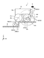
- FIG. 1 is a schematic side view showing a mobile robot according to an embodiment.
- FIG. 2 is a schematic perspective view showing a state where the cover is removed from the mobile robot shown in FIG.
- FIG. 3 is a schematic plan view of the mobile robot shown in FIG.
- FIG. 4 is a schematic side view of the mobile robot.
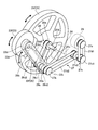
- FIG. 5 is a schematic perspective view showing the main wheel, the arm, the auxiliary wheel, the first power transmission mechanism, and the like shown in FIG.
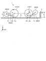
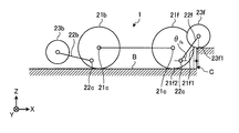
- FIG. 6 is a schematic side view schematically showing each element constituting the mobile robot.
- FIG. 7A is a schematic side view schematically showing the mobile robot.
- FIG. 7B is a schematic side view schematically showing the mobile robot.
- FIG. 7C is a schematic side view schematically showing the mobile robot.
- FIG. 7A is a schematic side view schematically showing the mobile robot.
- FIG. 7B is a schematic side view schematically showing the mobile robot.
- FIG. 7C is a schematic side view schematically showing the mobile robot
- FIG. 8 is a block diagram showing the configuration of the mobile robot.
- FIG. 9 is a block diagram showing a configuration of the step overcoming control unit shown in FIG.
- FIG. 10 is a flowchart showing the steps of stepping over the steps of the mobile robot.
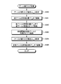
- FIG. 11 is a flowchart showing an outline of the position correction / step height acquisition process.
- FIG. 12 is a schematic plan view of the mobile robot.
- FIG. 13A is a schematic plan view of a mobile robot.
- FIG. 13B is a schematic plan view of the mobile robot.
- FIG. 14A is a schematic plan view of a mobile robot.
- FIG. 14B is a schematic plan view of the mobile robot.
- FIG. 14C is a schematic plan view of the mobile robot.
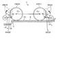
- FIG. 15 is a schematic side view of the mobile robot.
- FIG. 15 is a schematic side view of the mobile robot.
- FIG. 16 is a flowchart showing an outline of the arm swing-down process.
- FIG. 17 is a schematic side view showing a mobile robot.
- FIG. 18 is a schematic side view showing a mobile robot.
- FIG. 19 is a schematic side view showing a mobile robot.
- FIG. 20 is a flowchart showing an outline of the arm swinging process.
- FIG. 21 is a schematic side view showing a mobile robot.
- the moving body is a mobile robot including a moving mechanism using wheels.
- FIG. 1 is a schematic side view showing a mobile robot 1 according to an embodiment.
- 2 is a schematic perspective view showing a state where a cover (described later) is removed from the mobile robot 1 shown in FIG. 1
- FIG. 3 is a schematic plan view of the mobile robot 1 shown in FIG.
- FIG. 1 shows a Z-axis in which the vertical upward direction is a positive direction and a vertical downward direction is a negative direction, the left-right direction on the paper surface is the X-axis, and the front side to the back direction is the Y-axis.
- a three-dimensional orthogonal coordinate system is illustrated. Such an orthogonal coordinate system may also be shown in FIGS. 2 and 3 and other drawings used in the following description.
- the mobile robot 1 moves with the positive direction of the X axis as the traveling direction A (see FIG. 1). Further, in the following, the description such as left and right or front and rear means the left and right direction or front and rear direction with respect to the traveling direction A of the mobile robot 1.
- the mobile robot 1 includes a moving main body 10, a moving unit 20, and a control unit 30.
- the moving main body 10 includes a frame 11 and a cover 12 (shown only in FIG. 1). 2 and 3, the frame 11 is formed in, for example, a substantially rectangular parallelepiped shape, and has an upper surface and a lower surface opened in the vertical direction.
- the cover 12 is formed in, for example, a hollow substantially rectangular parallelepiped shape, and the lower surface is opened in the vertical direction.
- the cover 12 is attached to the frame 11 such that the opening portion on the lower surface is aligned with the opening portion on the upper surface of the frame 11.
- an internal space 13 is formed inside the movable main body 10, and the controller 30 and various motors to be described later are accommodated therein.
- the shapes of the frame 11 and the cover 12 described above are examples and are not limited, and may be, for example, a cube shape or a disk shape.
- the lower surface is opened in the frame 11, for example, the opening on the lower surface may be closed with a bottom plate or the like to prevent dust and the like from entering the internal space 13.
- the moving unit 20 includes a main wheel 21, an arm 22, and a sub wheel 23.
- the front arm 22 is operated to place the auxiliary wheel 23 on the step surface C1 of the step C on the road surface B, and the auxiliary wheel 23 is further pushed down to move the moving main body 10.
- the step C is overcome.
- the rear arm 22 is swung down so that the auxiliary wheel 23 is grounded to the road surface B, and further, the auxiliary wheel 23 is pushed down, while maintaining the posture of the moving main body 10 horizontal. , To get over the step C.
- the main wheels 21 are rotatably attached to the front left and right side surfaces and the rear left and right side surfaces of the moving main body 10 in the traveling direction A, respectively.
- the pair of main wheels 21 in front of the moving main body 10 may be referred to as “front wheels 21f” and the pair of main wheels 21 in the rear may be referred to as “rear wheels 21b”.
- the main wheels 21 are connected to drive motors (drive sources) 24 that are associated one-on-one.
- the driving force of the driving motor 24 is transmitted to the corresponding main wheel 21, and the main wheel 21 is rotationally driven in the forward direction or the reverse direction.
- all the main wheels 21 function as drive wheels, and each drive independently. Therefore, for example, by changing the rotational speed of the main wheel 21 by the drive motor 24 on the left and right, the direction of the traveling direction A of the movable body 10 can be changed.
- the drive motor 24 described above is housed inside the movable body 10.
- the moving unit 20 of the mobile robot 1 adopts a four-wheel drive system.
- the moving unit 20 does not have to be a four-wheel drive system, and may be, for example, a two-wheel drive system with one front and rear wheel, or a three-wheel drive system with two front wheels and one rear wheel.
- each of the drive motors 24 is individually controlled by the control unit 30 housed in the movable body unit 10.
- the arrangement position of the control unit 30 is not limited to the illustrated example.
- the control unit 30 may be separated from the mobile robot 1 and may be arranged to perform remote control via wireless communication or the like. Details of the configuration of the control unit 30 will be described later with reference to FIG.
- encoders 25 are attached to the drive motors 24, respectively.
- the encoder value indicating the rotation amount and rotation angle of the drive motor 24 output from the encoder 25 is output to the control unit 30.
- the arm 22 is formed in a long plate shape, and its inside is hollow.
- the arm 22 is attached so that the base end portion 22a (see FIG. 1) can swing on the front left and right side surfaces and the rear left and right side surfaces of the moving body portion 10 in the traveling direction A, respectively.
- Each arm 22 is attached at a position corresponding to the main wheel 21 described above.
- the pair of arms 22 at the front of the movable body 10 may be referred to as “front arms 22f” and the pair of arms 22 at the back may be referred to as “rear arms 22b”.
- FIG. 4 is a schematic side view of the mobile robot 1.
- the mobile robot 1 is schematically shown by representing the arm 22 with a straight line from the viewpoint of making the explanation easy to understand.
- the arm 22 is attached to the movable body 10 with the swing center shaft 22 c offset from the rotation center shaft 21 c of the main wheel 21.
- the swing center shaft 22 c of the arm 22 is offset downward in the vertical direction (Z-axis direction) with respect to the rotation center shaft 21 c of the main wheel 21.
- the offset amount D z is, for example, A value smaller than D m / 2 is set.
- the offset amount D z is set to D m / 4, for example.
- the swinging central axis 22c of the arm 22 is offset to the end face side of the moving main body 10 with respect to the rotational central axis 21c of the main wheel 21 in a side view.
- the swing center shaft 22 c is offset from the rotation center shaft 21 c of the main wheel 21 toward the front surface 10 f of the moving main body 10.
- the swing center shaft 22 c is offset from the rotation center shaft 21 c of the main wheel 21 toward the rear surface 10 b of the moving main body 10.
- the offset distance D a is set to a value smaller than D m / 2, for example.
- the offset distance D a is preferably set to D m / 4, for example.
- the offset amount Dz and the offset distance Da were specifically shown above, this is an illustration to the last and is not limited.
- the swing center shaft 22c of the arm 22 is offset with respect to the rotation center shaft 21c of the main wheel 21, the space for the arm 22 to swing (shown by the broken line E1) is reduced. As a result, the mobile robot 1 can be reduced in size.
- the rear auxiliary wheel 23b (described later) of the rear arm 22b is grounded to the road surface B on the front side in the traveling direction of the step C. Therefore, the length of the rear arm 22b is set to a value that can cope with such a scene.
- the front auxiliary wheel 23f (described later) of the front arm 22f is first grounded to the road surface B below the step C, so the length of the front arm 22f is It is set to a value that can handle such a scene.
- the auxiliary wheel 23 is grounded to the road surface B when the step C is raised or lowered.
- the length of the arm needs to be longer than that of the offset arm 22.
- the space for the arm to swing is as shown by a broken line E2.
- the swinging rotation shaft 22c is offset with respect to the rotation center shaft 21c of the main wheel 21, so that the swinging space E1 of the arm 22 is coaxial. It can be made smaller than the arm swinging space E2. In particular, the swinging space E1 when the arm 22 is swung up can be made smaller than E2. Therefore, as a result, the mobile robot 1 can be reduced in size while maintaining high step-over performance.
- the mobile robot 1 moves by driving the main wheel 21 during normal travel, the mobile robot 1 is simple while maintaining travel efficiency as compared with a mobile robot having a complex travel mechanism such as a leg wheel mechanism. It is possible to get over the level difference C of the road surface B with the configuration.
- the arm 22 is disposed between the side surface of the moving main body 10 and the main wheel 21 in the Z-axis direction view (top view).
- the arm 22 is connected to the arm motor 26 in one-to-one correspondence via a first power transmission mechanism 27 (not visible in FIG. 1).
- Each of the arm motors 26 is individually controlled by the control unit 30 like the drive motor 24.
- the arm motor 26 is fixed to the side surface of the movable body 10 such that a part of the body 26 a is exposed to the outside of the movable body 10. At this time, the output side of the main body 26 a of the arm motor 26 is positioned in the internal space 13 of the movable main body 10. Further, the first power transmission mechanism 27 is housed inside the movable body 10.
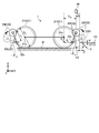
- FIG. 5 is a schematic perspective view showing the main wheel 21, the arm 22, the auxiliary wheel 23, the first power transmission mechanism 27, and the like shown in FIG.
- the main wheel 21 (front wheel 21 f) and the arm 22 (front arm 22 f) on the right front side of the moving main body 10 in the traveling direction A are shown.
- the configuration of the arm 22, the first power transmission mechanism 27, and the like will be described with reference to FIG. 5, but the arms 22 and the like provided on the front, rear, left, and right of the moving main body portion 10 have substantially the same configuration. Is also applicable to the arm 22 provided on the left front side or the rear side of the movable body 10.
- the first power transmission mechanism 27 includes a drive pulley 27a, a driven pulley 27b, an intermediate shaft 27c, a first belt 27d1, and a second belt 27d2.
- the drive pulley 27 a is connected to an output shaft (not shown) of the arm motor 26.
- the driven pulley 27 b is connected to the base end portion 22 a of the arm 22. At this time, the driven pulley 27 b is connected to the base end portion 22 a of the arm 22 through an insertion hole (not shown) drilled in the side surface of the moving main body portion 10. Therefore, the arm 22 is positioned outside the moving main body 10, and the driven pulley 27 b is positioned inside the moving main body 10 (internal space 13).
- the intermediate shaft 27c is rotatably supported by the movable body 10.
- the intermediate shaft 27c is provided with a first intermediate pulley 27c1 at one end and a second intermediate pulley 27c2 at the other end.
- the drive pulley 27a, the driven pulley 27b, and the first and second intermediate pulleys 27c1 and 27c2 of the intermediate shaft 27c are substantially parallel to each other.
- the first belt 27d1 is wound around the drive pulley 27a and the first intermediate pulley 27c1.
- the second belt 27d2 is wound around the second intermediate pulley 27c2 and the driven pulley 27b.
- the driving force of the arm motor 26 is transmitted to the first intermediate pulley 27c1 of the intermediate shaft 27c via the drive pulley 27a and the first belt 27d1, and the intermediate shaft 27c is rotated.
- the second intermediate pulley 27c2 also rotates with the rotation of the intermediate shaft 27c, and the rotational force is transmitted to the arm 22 via the second belt 27d2 and the driven pulley 27b, so that the arm 22 is pivoted about the swing center shaft 22c. It can be swung around.
- the rotational driving force of the arm motor 26 can be decelerated by the first power transmission mechanism 27 and transmitted to the arm 22.
- the diameter of the drive pulley 27a is made smaller than that of the first intermediate pulley 27c1
- the diameter of the second intermediate pulley 27c2 is set smaller than that of the driven pulley 27b. 27 is caused to function as a speed reduction mechanism.
- the rotational driving force of the arm motor 26 is decelerated by the first power transmission mechanism 27.
- the present invention is not limited to this.
- the arm driving force is not decelerated or increased to the arm 22. You may make it transmit.
- the arms 22 are connected to different arm motors 26, the arms 22 can be driven independently. Therefore, for example, even when the height S is a difference in level C between the left and right, the front auxiliary wheels 23f are controlled by the height C by individually controlling the operations of the left and right front arms 22f. It is also possible to get over the step C by placing it on the step surface C1.
- an encoder 28 (see FIG. 8) is attached to each arm motor 26.
- the encoder value indicating the rotation amount and rotation angle of the arm motor 26 output from the encoder 28 is input to the control unit 30.
- the auxiliary wheel 23 is rotatably attached to the tip 22d of the arm 22. As shown in FIG. 3, the auxiliary wheel 23 is disposed between the arm 22 and the main wheel 21 in the Z-axis direction view (top view).
- the pair of auxiliary wheels 23 in front of the moving main body 10 may be referred to as “front auxiliary wheels 23 f”, and the pair of rear auxiliary wheels 23 may be referred to as “rear auxiliary wheels 23 b”.
- the arm 22 and the auxiliary wheel 23 are set as an “initial position” where the arm 22 is swung up and the auxiliary wheel 23 is separated from the road surface B.
- the auxiliary wheel 23 is configured such that the arm 22 is swung down and grounded on the road surface B when the mobile robot 1 moves up and down the step C as will be described later.
- the corresponding driving motor 24 for the main wheel 21 is connected to the auxiliary wheel 23 via the second power transmission mechanism 29.
- the second power transmission mechanism 29 is disposed outside the moving main body 10, and a part of the second power transmission mechanism 29 is located in a hollow portion inside the arm 22.
- the second power transmission mechanism 29 includes a drive pulley 29a, a driven pulley 29b, an intermediate shaft 29c, a first belt 29d1, and a second belt 29d2.
- the drive pulley 29 a is connected to the output shaft (not shown) of the drive motor 24 via the axle 21 d of the main wheel 21.
- the driven pulley 29 b is connected to the axle 23 d of the auxiliary wheel 23.
- the driven pulley 29 b is positioned in a hollow portion inside the arm 22.
- the intermediate shaft 29c is rotatably supported by the moving main body 10.
- the intermediate shaft 29c is provided with a first intermediate pulley 29c1 at one end and a second intermediate pulley 29c2 at the other end. Similar to the driven pulley 29b, the second intermediate pulley 29c2 of the intermediate shaft 29c is positioned in a hollow portion inside the arm 22.
- the drive pulley 29a, the driven pulley 29b, and the first and second intermediate pulleys 29c1 and 29c2 of the intermediate shaft 29c are substantially parallel to each other.
- the first belt 29d1 is wound around the drive pulley 29a and the first intermediate pulley 29c1.
- the second belt 29d2 is wound around the second intermediate pulley 29c2 and the driven pulley 29b. As described above, since the second intermediate pulley 29c2 and the driven pulley 29b are positioned in the hollow portion of the arm 22, the second belt 29d2 is also positioned in the hollow portion of the arm 22.
- the arrangement space (occupied space) of the arm 22 and the second power transmission mechanism 29 can be reduced, and as a result.
- the entire mobile robot 1 can be reduced in size.
- the driving force of the driving motor 24 is the first intermediate of the intermediate shaft 29c via the axle 21d of the main wheel 21, the driving pulley 29a, and the first belt 29d1.
- Transmission to the pulley 29c1 causes the intermediate shaft 29c to rotate.
- the second intermediate pulley 29c2 also rotates, and the rotational force is transmitted to the auxiliary wheel 23 via the second belt 29d2, the driven pulley 29b, and the axle 23d. It is rotated around the shaft 23c.
- the rotational driving force of the driving motor 24 can be decelerated by the second power transmission mechanism 29 and transmitted to the auxiliary wheel 23.
- the diameter of the drive pulley 29a is made smaller than that of the first intermediate pulley 29c1
- the diameter of the second intermediate pulley 29c2 is set smaller than that of the driven pulley 29b. 29 is caused to function as a speed reduction mechanism.
- the rotational driving force of the drive motor 24 is decelerated by the second power transmission mechanism 29.
- this is only an example, and is not limited. You may make it transmit to the subwheel 23.
- the drive motor 24 is connected to both the main wheel 21 and the sub wheel 23 corresponding to drive the main wheel 21 and the sub wheel 23. That is, since the drive motor 24 is also used as the drive source for the main wheel 21 and the drive source for the auxiliary wheel 23, a motor dedicated to the auxiliary wheel 23 can be eliminated, and the mobile robot 1 can be downsized accordingly. it can.
- the auxiliary wheels 23 are connected to different driving motors 24, the auxiliary wheels 23 function as driving wheels and can be driven independently. Therefore, for example, when the vehicle travels over the step C, the rotation speed of the auxiliary wheel 23 is varied between the left and right, so that an operation such as changing the direction of the traveling direction A of the moving main body 10 while overcoming the step C is also possible. .
- the configuration of the second power transmission mechanism 29 is not limited to the above, and a clutch may be interposed between the drive motor 24 and the auxiliary wheel 23, for example.
- a clutch may be interposed between the drive motor 24 and the auxiliary wheel 23, for example.
- the driving motor 24 and the auxiliary wheel 23 can be connected by the clutch, and the auxiliary wheel 23 can be driven to rotate.
- the mobile robot 1 further includes a level difference detection unit 40 that detects a level difference C on the road surface B.
- a level difference detection unit 40 that detects a level difference C on the road surface B.
- the level difference detection unit 40 is attached to the upper surface 10 u of the movable body 10 (precisely, the upper surface of the cover 12) via an attachment member 41.
- the position of the level difference detection unit 40 relative to the moving main body 10 is indicated by an imaginary line.
- step difference detection parts 40 might be provided in the above, it is not limited to this, For example, one or 3 or more may be sufficient.
- the level difference detection units 40 are respectively attached to the left and right sides in front of the moving main body 10 in the traveling direction A. Specifically, the level difference detection unit 40 is disposed at a position separated from the front surface 10f of the moving main body 10 toward the traveling direction A side.
- the level difference detection unit 40 for example, a laser displacement meter that measures the distance from the attachment position of the attachment member 41 to the road surface B (indicated by a dashed arrow in FIG. 1) can be used.
- a signal indicating the distance to the road surface B output from the level difference detection unit 40 is input to the control unit 30.
- the control unit 30 calculates the height of the step C based on the input signal, and determines that there is a step C immediately below the step detection unit 40 when the height is greater than the threshold value.
- the laser displacement meter is taken as an example of the step detection unit 40, but the present invention is not limited to this.
- the distance to the road surface B may be measured using a capacitance sensor or the like.
- the level difference C may be detected by providing the level difference detection unit 40 with, for example, a camera and analyzing the image captured by the camera.
- FIG. 6 is a schematic side view schematically showing each element constituting the mobile robot 1.
- the mobile robot 1 is shown in a simplified manner by omitting the moving main body 10 or representing the arm 22 by a straight line for the sake of convenience of understanding.
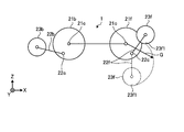
- each component of the mobile robot 1 is defined by symbols shown in FIG. Specifically, as follows: D m : Diameter of the main wheel 21 D s : Diameter of the auxiliary wheel 23 D z : Offset amount in the Z-axis direction (vertical downward direction) from the rotation center axis 21 c of the main wheel 21 to the swing center axis 22 c of the arm 22 D x : Offset amount in the X-axis direction from the rotation center axis 21c of the main wheel 21 to the swing center axis 22c of the arm 22 L a : length of the arm 22 ⁇ f : formed by the front arm 22f and a horizontal plane (XY plane) Angle ⁇ b : Angle formed by the rear arm 22b and the horizontal plane (XY plane) S: Height of the step C.
- D m Diameter of the main wheel 21
- D s Diameter of the auxiliary wheel 23
- D z Offset amount in the Z-axis direction (vertical downward direction) from the rotation center
- ⁇ fs angle between the front arm 22 f and the horizontal plane (XY plane) when the front auxiliary wheel 23 f contacts the step C
- ⁇ bs rear arm 22 b and the horizontal plane (XY) when the rear auxiliary wheel 23 b contacts the step C The angle formed with the plane.
- each parameter is set to satisfy the six conditions represented by the following equations (1) to (6). Each condition will be described with reference to FIGS. 7A to 7C.
- 7A to 7C are schematic side views schematically showing each element of the mobile robot 1.
- Condition 2 Since the front auxiliary wheel 23f rides on the step C, the lower end 23f1 of the front auxiliary wheel 23f can reach a position higher than the step C (see FIG. 7A).
- Condition 2 is expressed by the following formula (2).
- Condition 3 is expressed by the following formula (3).
- Condition 4 The distance (arrow G) between the rotation center shaft 21c of the front wheel 21f and the lower end 23f1 of the front auxiliary wheel 23f from the position when the front auxiliary wheel 23f rides on the step C to the position just below the front wheel 21f as indicated by the imaginary line. ) Is always larger than the radius of the front wheel 21f (see FIG. 7B).
- Condition 4 is expressed by the following formula (4).
- Condition 5 is expressed by the following equation (5).
- Condition 6 is expressed by the following formula (6).
- the mobile robot 1 can move up and down the step C having a height S by setting the parameters of each component so as to satisfy the above conditions 1 to 6.
- FIG. 8 is a block diagram showing the configuration of the mobile robot 1.
- FIG. 8 only components necessary for describing the present embodiment are shown, and descriptions of general components are omitted. Further, a plurality of components (for example, the drive motor 24 and the arm motor 26) are shown in one block for simplification of illustration, but actually, the plurality of components are individually separated. As described above, it is controlled.
- a plurality of components for example, the drive motor 24 and the arm motor 26
- the control unit 30 of the mobile robot 1 is a control device that controls the operation of the mobile robot 1 and includes, for example, a computer.
- the control unit 30 receives, for example, an operation command such as forward movement, backward movement, turning, stepping over a step, etc., from the host controller (or operator) (not shown), and the drive motor 24 according to the input operation command. And the operation of the arm motor 26 and the like are controlled.
- the control unit 30 may be configured to perform forward / reverse movement, turning, stepping over, etc., without depending on the operation command described above.
- control unit 30 includes a drive wheel control unit 31 and a step climbing control unit 32.
- the drive wheel control unit 31 is communicably connected to the step climbing control unit 32 and receives an encoder value of the encoder 25 of the drive motor 24 and the like.
- the drive wheel control unit 31 controls the operation of the drive motor 24 on the basis of a control command received from the step climbing control unit 32 and an encoder value of the encoder 25 as described later, and rotates the main wheel 21 and the sub wheel 23. Drive.
- the step climbing control unit 32 controls the operation of the mobile robot 1 so that the step climbing operation is executed autonomously in response to an operation command from the host controller, specifically, a step jump start command.
- Step output control unit 32 receives the output signal from step detection unit 40 and the encoder value of encoder 28 of arm motor 26.
- the step climbing control unit 32 controls the operation of the arm motor 26 based on the various signals inputted, and swings the arm 22. Further, the step climbing control unit 32 outputs a control command to the drive wheel control unit 31 when stepping over the step, and rotationally drives the main wheel 21 and the sub wheel 23 via the drive motor 24.
- FIG. 9 is a block diagram showing a configuration of the step overcoming control unit 32 shown in FIG.
- the step climbing control unit 32 includes a step climbing sequence processing unit 33, a step detection processing unit 34, and a motor control unit 35.
- the step climbing sequence processing unit 33 performs sequence processing for autonomously executing the step climbing operation. Specifically, the step climbing sequence processing unit 33 is based on the driving information (encoder value and the like) of the driving motor 24 and step detection values S R and S L (described later) obtained from the step detection processing unit 34. A control command related to the moving angle and the driving wheels (the main wheel 21 and the auxiliary wheel 23) is output. This process will be described later.
- the level difference detection processing unit 34 executes processing for calculating the left and right level difference detection values S R and S L from the outputs of the level difference detection units 40 provided on the left and right sides of the moving main body 10.
- the above-mentioned step detecting value S R is a value calculated from the right side of the step detecting section 40
- the step detection value S L is a value calculated from the left side of the step detecting section 40.
- the step detection processing unit 34 obtains output voltages A outR and A outL via the AD converter 34a when the output signals of the left and right step detection units 40 are input. Then, the step detection processing unit 34 supplies the output voltages A outR and A outL to the multiplier 34b and the filter 34c, and calculates the left and right step detection values S R and S L as shown in the following equation (7).
- the step detection values S R and S L are input to the step crossing sequence processing unit 33, and the average step detection value (C) of the step C is calculated from the left and right step detection values S R and S L using the following equation (8). The height C of the step C) is obtained.
- the function of the step climbing control unit 32 will be described.
- the angle control of the arm 22 is mainly performed. Since the angle command to the arm 22 is generated by the step climbing sequence processing unit 33, the motor control unit 35 outputs a value multiplied by the secondary filter 35 c as a position command to the arm motor 26.
- the position command correction amount ⁇ compx based on the admittance control includes a disturbance observer (DOBS (Disturbance Observer)) 35a for estimating the external force T ⁇ dx and a virtual mass spring damper surrounded by a broken line in FIG. It is obtained by a secondary filter 35b that simulates the system. Specifically, the calculation is performed according to the following equation (9).
- the position command ⁇ * mx to the arm motor 26 includes the position command correction amount ⁇ compx and a value obtained by supplying the position command ⁇ * x from the step climbing sequence processing unit 33 to the secondary filter 35c.
- the sum is calculated by the adder 35d.
- the position command ⁇ * mx is calculated using the following equation (10).
- the setting of the command filter here is, for example, an attenuation coefficient ⁇ of 1.0 and an angular frequency ⁇ n of about 2 ⁇ rad / s, but these are examples and are not limited.
- the position command ⁇ * mx is supplied to the position / speed control unit 36 on the arm motor 26 side, where a torque command T * mx is calculated, and the arm motor 26 is driven based on the calculated torque command T * mx. Is done.
- the subscript x in each of the above formulas and formulas described later indicates the front / rear and left / right arms 22, and for example, ⁇ * x is ⁇ * fr in the order of the right front, left front, right rear, and left rear arms 22. , ⁇ * fl , ⁇ * br , ⁇ * bl , and the like.
- step overstep process of the mobile robot 1 executed by the control unit 30 of the mobile robot 1 (more precisely, the step crossing sequence processing unit 33 etc.) will be described.
- FIG. 10 is a flowchart showing a step overstep process of the mobile robot 1.
- the control unit 30 first determines whether or not a step overstep start command (hereinafter referred to as “start command”) is input from, for example, a host controller (step S10).
- start command a step overstep start command
- the control part 30 repeats the process of step S10, when a start command is not input (step S10, No). On the other hand, when the start command is input (step S10, Yes), the control unit 30 subsequently executes an exclusion process (step S11).
- This exclusive process is a process for preventing, for example, a process other than the emergency stop command from being accepted when the mobile robot 1 is under control for overcoming the step C.
- control unit 30 controls the operation of the drive motor 24 so that the mobile robot 1 moves forward at a predetermined speed Va (step S12).
- the predetermined speed Va is set to a relatively low value, for example, 0.02 m / s. Therefore, in the process of step S12, the mobile robot 1 is caused to travel at a relatively low speed.
- the specific value of the above-mentioned predetermined speed Va is an example and is not limited.
- specific numerical values may be given as examples of various values, but these are merely examples and are not limited.
- the control unit 30 determines whether or not the distance P1 that the mobile robot 1 has advanced is less than the threshold value P1a (step S13).
- the threshold value P1a is set to an appropriate value based on the size and application of the mobile robot 1, the place where the mobile robot 1 travels, and is set to 1 m, for example.
- step S13 determines that the forward distance P1 of the mobile robot 1 is less than the threshold value P1a (step S13, Yes)
- the step C is detected by at least one of the left and right step detection units 40. It is determined whether or not it has been done (step S14).
- step S14 specifically, the presence or absence of the step C is determined based on whether or not at least one of the left and right step detection values S R and S L is greater than the threshold value Sa. Is larger, it is determined that there is a step C on the road surface B.
- the threshold value Sa is set to 0.01 m, for example.
- step S14 When the step C is not detected by any of the left and right step detection units 40 (step S14, No), the control unit 30 returns to the process of step S12 and continues the forward operation. In addition, when the step C is detected by any of the left and right step detection units 40 (step S14, Yes), the control unit 30 then executes position correction / step height acquisition processing of the mobile robot 1 (step S15). ).
- FIG. 11 is a flowchart showing an outline of the position correction / step height acquisition process in step S15 of FIG.
- control unit 30 first advances the mobile robot 1 by a predetermined distance P2 (step S100), and then determines whether or not the level difference C is detected by both the left and right level difference detection units 40 (step S100). Step S101).
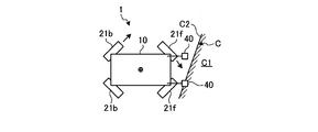
- FIGS. 12, 13A, and 13B are schematic plan views of the mobile robot 1.
- FIG. 12 and the like illustration of the arm 22, the auxiliary wheel 23, and the like is omitted for simplification of the drawing.
- L s represents the separation distance between the left and right level difference detection units 40
- ⁇ a is defined by the straight line 10 f 1 parallel to the front surface 10 f of the moving main body 10 and the side wall surface C 2 of the level difference C. Represents an angle.
- ⁇ a in FIG. 12 is an upper limit value of an angle at which the mobile robot 1 can get over the step C even if the mobile robot 1 is inclined with respect to the side wall C2 of the step C.
- theta a is the acceptance angle for the step C of the mobile robot 1.
- the predetermined distance P2 is obtained by L s sin ( ⁇ a ) using the above-described separation distance L s and the allowable angle ⁇ a (see FIG. 12).
- the mobile robot 1 is advanced by a predetermined distance P2 in step S100, and the level difference detection unit 40 of the left and right level detection units 40 is determined in step S101. In both cases, it is determined whether or not the step C is detected.
- the angle with respect to the side wall surface C2 of the mobile robot 1 is an allowable angle. it is within the range of ⁇ a. Therefore, the direction of the moving main body 10 is not corrected, and the operation proceeds to step over the step as it is.
- step S101, No the control unit 30 detects the level difference C on one of the left and right level difference detection units 40, and the level difference is detected on the other side.
- the direction of the moving main body 10 is corrected in step S102 and subsequent steps. Specifically, after step S102, the orientation of the moving main body 10 is corrected so that the moving main body 10 faces the side wall surface C2 of the step C.
- control unit 30 controls the operation of the drive motor 24, specifically, the operation of the main wheel 21 so that the mobile robot 1 performs a pivoting operation at a predetermined angular velocity ⁇ (step S102).
- FIGS. 14A to 14C are schematic plan views of the mobile robot 1.
- FIG. 14A shows a scene in which, for example, of the left and right level difference detection units 40, the level difference C is detected by the right level difference detection unit 40 and the level difference C is not detected by the left level difference detection unit 40.
- this scene will be described as an example.
- control unit 30 rotates the main wheel 21 on the side where the step C is not detected among the left and right main wheels 21, that is, the left main wheel 21 in the direction in which the moving main body unit 10 moves forward.
- the operation of the drive motor 24 is controlled.
- the right main wheel 21 is stopped. Accordingly, the left level difference detection unit 40 is gradually approached toward the level difference C.
- FIG. 14A and the like the orientation of the main wheel 21 is changed in order to make it easy to understand the pivoting operation.
- a mechanism for actually steering the main wheel 21 is provided, and as shown in FIG. You may make it perform a belief turning operation
- FIG. 14A a mechanism for actually steering the main wheel 21 is provided, and as shown in FIG. You may make it perform a belief turning operation
- the left main wheel 21 in which the step C is not detected is rotated in the forward direction
- the present invention is not limited to this
- the right main wheel 21 in which the step C is detected is It may be rotated in the reverse direction to perform the belief turning operation. Furthermore, it may be a so-called super-spinning where the left and right main wheels 21 have different rotation directions.
- control unit 30 determines whether or not the turning angle P ⁇ due to the belief turning is less than the threshold value P ⁇ a (step S103).
- This threshold value P ⁇ a is, for example, 45 degrees.
- step S104 is processing for determining whether or not the movable main body unit 10 is in a state as shown in FIG. 14B.
- the control unit 30 returns to the process of step S102 when the level difference C is not detected by the level difference detection unit 40 on the left side (step S104, No).
- the control unit 30 turns the belief by a predetermined turning angle R ⁇ in the direction opposite to the turning direction in step S102.
- An operation is performed (step S105). Specifically, the control unit 30 in this case controls the operation of the driving motor 24 so that the right main wheel 21 rotates in the direction in which the moving main body unit 10 moves forward, for example.
- the predetermined turning angle R ⁇ is set to a value smaller than the turning angle P ⁇ that is turned from the first execution of the process of step S102 to the affirmative in step S104, for example, about half of the turning angle P ⁇ .
- control unit 30 pivots the moving main body part 10 so as to return it slightly in the opposite direction, so that the moving main body part 10 in the state shown in FIG. 14B is moved to the side wall surface of the step C as shown in FIG. 14C.
- the direction of the moving main body 10 is corrected so that the moving main body 10 faces the side wall surface C2 of the step C.
- the mobile robot 1 can reliably get over the step C in the step-over operation of the step C described later.
- the range of operation when the mobile body 10 faces the side wall surface C2 can be reduced. it can.
- the control unit 30 determines that some abnormality has occurred when turning to that level and the step detection unit 40 does not detect the step C. Then, the process returns to the flowchart of FIG.
- the control unit 30 corrects the direction of the mobile body unit 10 and then controls the operation of the drive motor 24 so that the mobile robot 1 moves forward at a predetermined speed Va (step S106).
- control unit 30 determines whether or not the distance P3 advanced by the mobile robot 1 by the process of step S106 is less than the threshold value P3a (step S107).
- the threshold value P3a is set to 10 cm, for example.
- control unit 30 determines whether or not the step C is detected by both of the step detection units 40 (step S108). ).
- the control unit 30 returns to the process of step S106 when the level difference C is not detected by both the left and right level difference detection units 40 (No in step S108).
- the control unit 30 determines that an abnormality has occurred when the step is advanced to that point and the step C is not detected by the step detection unit 40. Then, the process returns to the flowchart of FIG.
- control unit 30 When the level difference C is detected by both the left and right level difference detection units 40 (step S108, No), the control unit 30 subsequently calculates the detected height S of the level difference C, more precisely, the average level difference detection value S. Obtain (step S109). About this, it calculates using Formula (8) mentioned above.
- control unit 30 controls the operation of the main wheel 21 and adjusts the position of the moving main body unit 10 so that the front auxiliary wheel 23f contacts the predetermined position of the step C (step S110).
- FIG. 15 is a schematic side view of the mobile robot 1 for explaining the adjustment of the position of the mobile main body 10.
- the predetermined position means a position where the front auxiliary wheel 23f can ride reliably and stably on the step surface C1.
- the moving body 10 by reverse distance x 2 is retracted, it is assumed that grounds the previous sub-wheels 23f to a predetermined position of the step surface C1 of the step C.
- Treatment distance x 2 is the lower end of the Z-axis distance in the direction alpha, before the side wall surface C2 of the step C in the side view the sub wheels 23 from the stepped surface C1 of the step C in the side view and the lower end 23f1 of the front sub-wheels 23f 23f1
- the distance in the X-axis direction is defined as ⁇
- the terminal position ⁇ * fn of the arm 22 in the equation (11) is obtained from the following equation (12).
- control unit 30 as the moving body 10 moves by reverse distance x 2 calculated, and controls the operation of the main wheel 21 through the driving motor 24.
- the front auxiliary wheel 23f can be reliably and stably placed on the step surface C1 of the step C.
- step S111 the control unit 30 sets a flag indicating that the position correction has been completed normally (step S111), and returns to the flowchart of FIG.
- step S101, Yes the mobile robot 1 is in the state shown in FIG. 13B, and thus the process proceeds to step S111 without correcting the position. Then, the above processing is performed.
- control unit 30 determines whether or not the position correction has been normally completed, that is, determines whether or not the above-described flag is set (step S16).
- the control unit 30 executes an arm swinging process (step S17).
- FIG. 16 is a flowchart showing an outline of the arm swing-down process.
- the control unit 30 first sets the swing-down speed ⁇ max 1 of the arm 22 (step S200).
- the swing-down speed ⁇ max 1 is set to a relatively high value, for example, 30 deg / s.
- control unit 30 swings the front and rear arms 22 so as to swing down to the end position ⁇ * fn at the swing-down speed ⁇ max 1 set in step S200 (step S201).
- the end position ⁇ * fn is obtained by the above equation (12).
- the front arm 22f is swung down at a relatively high speed from the initial position indicated by the solid line to the terminal position ⁇ * fn indicated by the imaginary line.
- the rear arm 22b is also swung down at a relatively high speed from the initial position to the end position ⁇ * bn indicated by the imaginary line.
- the end position ⁇ * fn and the end position ⁇ * bn are set to the same value.
- control unit 30 sets the swing-down speed ⁇ max 2 of the arm 22 (step S202).
- the swing-down speed ⁇ max 2 is set to a value lower than the value set in step S200, for example, 10 deg / s.
- the control unit 30 swings the front arm 22f so as to swing down to the end position ⁇ * fe (described later) at the swing-down speed ⁇ max 2 set in step S202 (step S203).
- FIG. 17 is a schematic side view showing the mobile robot 1 at that time. As shown in FIG. 17, the front auxiliary wheel 23f is grounded to the road surface B, more precisely, to the step surface C1 of the step C by the process of step 203.
- control unit 30 swings the rear arm 22b so as to swing it down in synchronization with the front arm 22f to the end position ⁇ * be (described later) at the swing speed ⁇ max 2 set in step S202 ( Step S204).
- the rear auxiliary wheel 23b is grounded to the road surface B.
- control unit 30 moves the rear auxiliary wheel 23b while synchronizing it with the front and rear arms 22f and 22b (step S205).
- FIG. 18 is a schematic side view showing the mobile robot 1 for explaining the processing of steps S203 to S205.
- the front arm 22f and the rear arm 22b are cooperated so as to get over the movable body 10 while maintaining a predetermined posture, for example, level. Make it work.
- the condition for maintaining the moving main body 10 horizontally is expressed by the following equation (13).
- control angle command for the rear arm 22b for maintaining the movable main body 10 horizontally is calculated by the following equation (14) based on the angle of the front arm 22f.
- the arm swing end positions ⁇ * fe and ⁇ * be are calculated by the equations (16) and (17) in consideration of the margin ⁇ because the contact point of the main wheel 21 only needs to exceed the step C. .
- the terminal positions ⁇ * fe and ⁇ * be are used in steps S203 and S204.
- control unit 30 operates the front and rear arms 22f and 22b in cooperation with each other so as to get over the movable body 10 while maintaining a predetermined posture, for example, level.
- the mobile robot 1 since the balance of the center of gravity is maintained when the mobile robot 1 gets over the step C, the mobile robot 1 can reliably get over the step C without rolling over. Further, for example, when the mobile robot 1 is used for carrying an object, it is possible to prevent the object from falling by maintaining the posture of the moving main body unit 10 horizontally when climbing over the step C.
- the load acting on the arm 22 from the movable body 10 when the movable body 10 is lifted can be dispersed, and the arm 22 and the arm motor 26 can be downsized. You can also
- the predetermined posture of the moving main body 10 is not limited to horizontal, and for example, the moving main body 10 may be inclined forward or backward, or may be inclined left or right. Good.
- control unit 30 then moves the mobile robot 1 forward at a predetermined speed Va by a predetermined distance P4 (step S18).
- the predetermined distance P4 is set to a value approximately the same as the length (full length) of the mobile robot 1 in the traveling direction A, for example.
- FIG. 19 is a schematic side view showing the mobile robot 1 after moving forward by a predetermined distance P4. As shown in FIG. 19, the mobile robot 1 is brought into a state where both the front wheel 21f and the rear wheel 21b are moved to the level difference surface C1 of the level difference C by the process of step S18.
- the main wheel 21 is separated from the step surface C1 of the step C as shown in FIG.
- the main wheel 21 may be in contact with the step surface C1.
- the mobile robot 1 can move forward by the predetermined distance P4 by the rotational drive of both the main wheel 21 and the sub wheel 23, and the time required to get over the step C can also be shortened.
- FIG. 20 is a flowchart showing an outline of the arm swinging process.
- the control unit 30 sets the swing speed ⁇ max 3 of the arm 22 (step S300).
- the swing-up speed ⁇ max 3 is set to a relatively low value, for example, 10 deg / s.
- the control unit 30 swings the front arm 22f to swing up to the end position ⁇ * fp (described later) at the swing speed ⁇ max 3 set in step S300 (step S301).
- FIG. 21 is a schematic side view showing the mobile robot 1 at that time. As shown in FIG. 21, the front auxiliary wheel 23 f is separated from the road surface B by a predetermined distance (margin ⁇ ) by the process of step 301.
- control unit 30 swings the rear arm 22b so as to be swung up in synchronization with the front arm 22f to the end position ⁇ * bp (described later) at the swing speed ⁇ max 3 set in Step S300 (Step S300). S302). Thereby, the rear auxiliary wheel 23b is also separated from the road surface B as shown in FIG.
- control unit 30 moves the rear auxiliary wheel 23b while synchronizing it with the front and rear arms 22f and 22b (step S303).
- the terminal positions ⁇ * fp and ⁇ * bp of the arm 22 at this time are calculated using the following equations (18) and (19) and used in steps S301 and S302. Further, as described above, when the arm is swung up, the arm 22 is operated at a low speed until the terminal positions ⁇ * fp and ⁇ * bp are reached.
- step S303 the movement amount dPosxb of the rear auxiliary wheel 23b at the time of swinging is also calculated using the following formula (20) in consideration of the formula (15) at the time of swinging down.
- control unit 30 sets the swing-up speed ⁇ max 4 of the arm 22 (step S304).
- the swing-up speed ⁇ max 4 is set to a value higher than the value set in step S300, for example, 30 deg / s.
- the control unit 30 swings the front and rear arms 22f and 22b so as to swing up to the end position ⁇ * init at the swing speed ⁇ max 4 set in step S304 ( Step S305). That is, the arm 22 and the auxiliary wheel 23 are returned to the initial positions by the process of step S305.
- the speed (swing-up speed ⁇ max 3) is set to be lower than the operating speed (swing-up speed ⁇ max 4) of the arm 22 from when the auxiliary wheel 23 moves away from the predetermined distance ⁇ to return to the initial position.
- step S20 the control unit 30 releases the exclusive process.
- the mobile robot 1 is switched from the step-over control to the normal control. In this way, the step over the step of the mobile robot 1 is completed.
- control part 30 does not have the level
- step S16 If it is determined in step S16 that the position correction has not been normally completed (No in step S16), the control unit 30 similarly determines that some abnormality has occurred and executes the program after processing in step S20. finish.
- the main wheel 21 is rotatably attached to the moving main body 10.
- the arm 22 is swingably attached to the movable body 10, and the swing center shaft 22 c is offset with respect to the rotation center shaft 21 c of the main wheel 21.
- the auxiliary wheel 23 is rotatably attached to the distal end portion 22 d of the arm 22.
- the control unit 30 controls the operation of the arm 22 according to the state of the road surface B, and grounds the auxiliary wheel 23 to the road surface B.
- the arm 22 and the auxiliary wheel 23 are respectively attached to the front and rear of the moving main body 10.
- the present invention is not limited to this.
- the arm 22 is provided only on the front side of the moving main body 10.
- the auxiliary wheel 23 may be attached.
- both the main wheel 21 and the auxiliary wheel 23 are driven by the drive motor 24, but the present invention is not limited to this. That is, another driving source may be connected to each of the main wheel 21 and the auxiliary wheel 23 and driven independently. Thereby, for example, only when the mobile robot 1 moves up and down the step C, the auxiliary wheel 23 can be driven to rotate. Further, in the drive source, it is only necessary to drive the corresponding main wheel 21 or auxiliary wheel 23, so that the size can be reduced.
- the drive motor 24 accommodated in the moving main body 10 has been described as an example of the drive source such as the main wheel 21, other drive sources such as an in-wheel motor may be used. It may be an internal combustion engine or the like.
- the mobile body is the mobile robot 1.
- the present invention is not limited to this.
- any configuration may be used as long as the vehicle moves, such as an automobile or a motorcycle. Good.
Landscapes
- Engineering & Computer Science (AREA)
- Chemical & Material Sciences (AREA)
- Combustion & Propulsion (AREA)
- Transportation (AREA)
- Mechanical Engineering (AREA)
- Manipulator (AREA)
- Control Of Position, Course, Altitude, Or Attitude Of Moving Bodies (AREA)
Abstract
実施形態に係る移動体にあっては、主車輪(21)と、アーム(22)と、副車輪(23)と、制御部(30)とを備える。主車輪(21)は、移動本体部(10)に回転可能に取り付けられる。アーム(22)は、移動本体部(10)に揺動可能に取付けられ、揺動中心軸(22c)が主車輪(21)の回転中心軸(21c)に対してオフセットされる。副車輪(23)は、アーム(22)の先端部(22d)に回転可能に取り付けられる。制御部(30)は、路面(B)の状態に応じてアーム(22)の動作を制御し、副車輪(23)を路面(B)に接地させる。
Description
開示の実施形態は、移動体に関する。
従来、車輪を用いた移動機構を備え、車輪で路面を走行して移動する移動体(例えば移動ロボットなど)が知られている。このような移動体は、例えば工場や研究所、オフィスといった様々な場所で、物を運搬したり、ゲストを案内したりといった多様な用途に用いられる。
移動体が走行する路面の状態は平坦とは限られず、例えばケーブルの配線や作業レイアウトの都合などから路面に段差があることも多い。そして、かかる段差の高さによっては、車輪を用いた移動機構がこれを乗り越えるのが難しいこともある。
そこで、段差による制限を受けることなく移動することができる移動機構、例えば無限軌道(クローラ)を備えた移動体や、本体に設けられた伸縮自在な脚部の先に車輪を有する脚車輪機構を備えた移動体が提案されている(例えば特許文献1参照)。
しかしながら、上記した無限軌道や脚車輪機構のような移動機構を備えた移動体にあっては、構成が複雑になるとともに、大型化してしまうという点で改善の余地があった。また、脚車輪機構などの複雑な機構は、単に車輪を用いた移動機構に比して、平常走行時の移動に多くの動力を要し、走行効率が低下するおそれがあった。
実施形態の一態様は、上記に鑑みてなされたものであって、走行効率を維持しつつ、小型でかつ簡素な構成で路面の段差を乗り越えることができる移動体を提供することを目的とする。
実施形態の一態様に係る移動体は、主車輪と、アームと、副車輪と、制御部とを備える。主車輪は、移動本体部に回転可能に取り付けられる。アームは、前記移動本体部に揺動可能に取付けられ、揺動中心軸が前記主車輪の回転中心軸に対してオフセットされる。副車輪は、前記アームの先端部に回転可能に取り付けられる。制御部は、路面の状態に応じて前記アームの動作を制御し、前記副車輪を路面に接地させる。
実施形態の一態様によれば、移動体において、走行効率を維持しつつ、小型でかつ簡素な構成で路面の段差を乗り越えることができる。
以下、添付図面を参照して、本願の開示する移動体の実施形態を詳細に説明する。なお、以下に示す実施形態によりこの発明が限定されるものではない。
また、以下に示す実施形態では、移動体が、車輪を用いる移動機構を備えた移動ロボットであるものとして説明を行う。
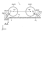
図1は、実施形態に係る移動ロボット1を示す模式側面図である。また、図2は図1に示す移動ロボット1においてカバー(後述)を取り外した状態を示す模式斜視図であり、図3は図2に示す移動ロボット1の模式平面図である。
なお、説明を分かり易くするために、図1には、鉛直上向きを正方向とし、鉛直下向きを負方向とするZ軸、紙面における左右方向をX軸、紙面手前から奥方向をY軸とした3次元の直交座標系を図示している。かかる直交座標系は、図2,3および後述の説明に用いる他の図面でも示す場合がある。
なお、本実施形態の説明において、移動ロボット1は、X軸の正方向を進行方向Aとして移動するものとする(図1参照)。また、以下において左右あるいは前後などの記載は、移動ロボット1の進行方向Aに対する左右方向あるいは前後方向を意味する。
図1に示すように、移動ロボット1は、移動本体部10と、移動部20と、制御部30とを備える。移動本体部10は、フレーム11と、カバー12(図1にのみ示す)とを備える。フレーム11は、図2,3によく示すように、例えば略直方体形状に形成されるとともに、鉛直方向において上面と下面とが開口される。
カバー12は、詳細な図示は省略するが、例えば中空の略直方体形状に形成され、鉛直方向において下面が開口される。カバー12は、下面の開口部分がフレーム11の上面の開口部分に合わさるようにしてフレーム11に取り付けられる。
これにより、移動本体部10の内側に内部空間13が形成されることとなり、そこには制御部30や後述する各種モータなどが収納される。なお、上記したフレーム11やカバー12の形状は例示であって限定されるものではなく、例えば立方体形状や円盤形状などであってもよい。また、フレーム11において下面を開口するようにしたが、例えば下面の開口を底板などで塞ぎ、粉塵などが内部空間13に侵入するのを防止するように構成してもよい。
移動部20は、主車輪21と、アーム22と、副車輪23とを備える。本実施形態に係る移動ロボット1にあっては、前側のアーム22を動作させて副車輪23を路面Bにある段差Cの段差面C1に乗せ、さらにその副車輪23を押し下げて移動本体部10を持ち上げつつ前進することで、段差Cを乗り越えるようにしている。また、移動本体部10を持ち上げる際、後側のアーム22を振り下げて副車輪23を路面Bに接地させ、さらにその副車輪23を押し下げることで、移動本体部10の姿勢を水平に保ちつつ、段差Cを乗り越えるようにしている。
以下詳説すると、主車輪21は、進行方向Aにおいて移動本体部10の前方の左右側面、および後方の左右側面にそれぞれ回転可能に取り付けられる。なお、以下においては、移動本体部10の前方の一対の主車輪21を「前輪21f」、後方の一対の主車輪21を「後輪21b」という場合もある。
主車輪21には、それぞれ1対1で対応付けられた駆動用モータ(駆動源)24が接続される。駆動用モータ24の駆動力は対応する主車輪21へ伝達され、主車輪21は正転方向あるいは逆転方向へ回転駆動する。
したがって、主車輪21はいずれも駆動輪として機能し、それぞれが独立して駆動する。そのため、例えば駆動用モータ24による主車輪21の回転速度を左右で異ならせることで、移動本体部10の進行方向Aの向きを変えることもできる。上記した駆動用モータ24は、移動本体部10の内部に収納される。
上記の如く、移動ロボット1の移動部20は、四輪駆動方式を採っている。なお、移動部20は、四輪駆動方式でなくともよく、例えば、前後輪1輪ずつの二輪駆動方式や、前2輪、後ろ1輪などの三輪駆動方式であってもよい。
ここで、駆動用モータ24のそれぞれは、移動本体部10に収納された制御部30によって個別に制御される。なお、制御部30の配置位置は図示した例に限られるものではなく、例えば、移動ロボット1とは分離され、無線通信などを介して遠隔制御を行うように配置されてもよい。制御部30の構成の詳細については、図8を用いて後述する。
また、図1などで図示を省略するが、駆動用モータ24には、それぞれエンコーダ25(図8参照)が取り付けられる。エンコーダ25から出力された、駆動用モータ24の回転量や回転角度を示すエンコーダ値は、制御部30へ出力される。
アーム22は、長尺の板状に形成され、その内部は中空とされる。また、アーム22は、基端部22a(図1参照)が、進行方向Aにおいて移動本体部10の前方の左右側面、および後方の左右側面にそれぞれ揺動可能に取り付けられる。また、アーム22はそれぞれ、上記した主車輪21に対応するような位置に取り付けられる。なお、以下においては、移動本体部10の前方の一対のアーム22を「前アーム22f」、後方の一対のアーム22を「後アーム22b」という場合もある。
ここで、アーム22の取り付け位置について図4を参照しつつ説明する。図4は、移動ロボット1の模式側面図である。なお、図4では、説明を分かりやすくする観点から、アーム22を直線で表すなどして、移動ロボット1をごく模式的に示している。
図4に示すように、アーム22は、揺動中心軸22cが主車輪21の回転中心軸21cに対してオフセットされて、移動本体部10に取り付けられる。詳しくは、アーム22の揺動中心軸22cは、主車輪21の回転中心軸21cよりも鉛直方向(Z軸方向)において下方にオフセットされる。
具体的には、主車輪21の直径をDm、主車輪21の回転中心軸21cから揺動中心軸22cまでの鉛直下向き方向におけるオフセット量をDzとした場合、オフセット量Dzは、例えばDm/2よりも小さい値に設定される。また、好ましくはオフセット量Dzは、例えばDm/4に設定される。
また、アーム22の揺動中心軸22cは、側面視において主車輪21の回転中心軸21cよりも移動本体部10の端面側にオフセットされる。具体的には、前アーム22fは、揺動中心軸22cが、主車輪21の回転中心軸21cよりも移動本体部10の前面10f側にオフセットされる。他方、後アーム22bは、揺動中心軸22cが、主車輪21の回転中心軸21cよりも移動本体部10の後面10b側にオフセットされる。
また、回転中心軸21cから揺動中心軸22cまでのオフセット距離をDaとした場合、オフセット距離Daは、例えばDm/2よりも小さい値に設定される。また、好ましくはオフセット距離Daは、例えばDm/4に設定される。なお、上記では、オフセット量Dzおよびオフセット距離Daを具体的に示したが、これはあくまでも例示であって、限定されるものではない。
上記のように、アーム22の揺動中心軸22cが主車輪21の回転中心軸21cに対してオフセットされることから、アーム22が揺動するためのスペース(破線E1で示す)を減少させることができ、結果として移動ロボット1を小型化することができる。
すなわち、移動ロボット1は、後述するように、例えば段差Cを乗り越えた後にも、後アーム22bの後副車輪23b(後述)が、段差Cの進行方向手前側の路面Bに接地される。そのため、後アーム22bの長さはそのような場面に対応できるような値に設定される。同様に、移動ロボット1が例えば段差Cを降りる場合も、前アーム22fの前副車輪23f(後述)が先に段差Cの下側の路面Bに接地されるため、前アーム22fの長さはそのような場面に対応できるような値に設定される。
したがって、図4に想像線で示す如く、例えば仮にアームの揺動中心軸が、主車輪21の回転中心軸21cと同軸であった場合、段差Cの昇降時に副車輪23を路面Bに接地させるには、アームの長さを、オフセットされたアーム22に比して長くする必要が生じる。その場合のアームが揺動するためのスペースは、破線E2で示すような大きさとなる。
これに対し、本実施形態におけるアーム22にあっては、揺動回転軸22cが主車輪21の回転中心軸21cに対してオフセットされることから、アーム22の揺動スペースE1を、同軸とされた場合のアームの揺動スペースE2に比して小さくすることができる。特に、アーム22を振り上げたときの揺動スペースE1をE2に比して小さくすることができる。よって、結果的に高い段差乗り越え性能を維持しつつ、移動ロボット1を小型化することができる。
また、移動ロボット1は、平常走行時には主車輪21を駆動して移動するため、例えば脚車輪機構などの複雑な移動機構を備えた移動ロボットに比して、走行効率を維持しつつ、簡素な構成で路面Bの段差Cを乗り越えることができる。
アーム22の説明を続けると、アーム22は、図3に示すように、Z軸方向視(上面視)において移動本体部10の側面と主車輪21との間に配置される。
アーム22には、それぞれ1対1で対応付けられたアーム用モータ26が第1動力伝達機構27(図1で見えず)を介して接続される。アーム用モータ26のそれぞれは、駆動用モータ24と同様、制御部30によって個別に制御される。
アーム用モータ26は、図3に示すように、本体部26aの一部が移動本体部10の外側に露出するようにして、移動本体部10の側面に固定される。このとき、アーム用モータ26の本体部26aにおける出力側は、移動本体部10の内部空間13に位置される。また、第1動力伝達機構27は、移動本体部10の内部に収納される。
図5は、図2に示す主車輪21、アーム22、副車輪23および第1動力伝達機構27などを取り出して示す模式斜視図である。なお、図5では、進行方向Aにおいて移動本体部10の右前方の主車輪21(前輪21f)やアーム22(前アーム22f)などを示している。以下では、図5に基づいてアーム22や第1動力伝達機構27などの構成を説明するが、移動本体部10の前後左右に設けられるアーム22などは略同一の構成であるため、以下の説明は、移動本体部10の左前方や後方に設けられるアーム22などにも妥当する。
図5に示すように、第1動力伝達機構27は、駆動プーリ27aと、従動プーリ27bと、中間軸27cと、第1ベルト27d1と、第2ベルト27d2とを備える。駆動プーリ27aは、アーム用モータ26の出力軸(図示せず)に接続される。
従動プーリ27bは、アーム22の基端部22aに接続される。このとき、従動プーリ27bは、移動本体部10の側面に穿設された挿通孔(図示せず)を通って、アーム22の基端部22aに接続される。したがって、アーム22は、移動本体部10の外側に位置され、従動プーリ27bは、移動本体部10の内側(内部空間13)に位置されることとなる。
中間軸27cは、移動本体部10に回転可能に支持される。また、中間軸27cは、一端に第1中間プーリ27c1が設けられる一方、他端に第2中間プーリ27c2が設けられる。上記した駆動プーリ27aと、従動プーリ27bと、中間軸27cの第1、第2中間プーリ27c1,27c2とは、互いの回転中心軸が略平行とされる。
なお、上記した「平行」や後述する「水平」などの語句は、必ずしも数学的に厳密な精度を必要とするものではなく実質的な公差や誤差などについては許容されるものである。
第1ベルト27d1は、駆動プーリ27aおよび第1中間プーリ27c1に巻き掛けられる。また、第2ベルト27d2は、第2中間プーリ27c2および従動プーリ27bに巻き掛けられる。
これにより、アーム用モータ26の駆動力は、駆動プーリ27a、第1ベルト27d1を介して中間軸27cの第1中間プーリ27c1へ伝達され、中間軸27cが回転される。そして、中間軸27cの回転に伴って第2中間プーリ27c2も回転し、その回転力は、第2ベルト27d2、従動プーリ27bを介してアーム22へ伝達され、よってアーム22は揺動中心軸22c回りに揺動させられる。
したがって、各プーリの直径を適宜に設定することで、アーム用モータ26の回転駆動力を第1動力伝達機構27で減速して、アーム22へ伝達することができる。具体的に例えば、駆動プーリ27aの直径を第1中間プーリ27c1のそれよりも小さくし、第2中間プーリ27c2の直径を従動プーリ27bのそれよりも小さく設定するなどして、第1動力伝達機構27を減速機構として機能させる。
なお、上記ではアーム用モータ26の回転駆動力を第1動力伝達機構27で減速するようにしたが、これに限定されるものではなく、例えば減速させずに、あるいは増速させてアーム22へ伝達するようにしてもよい。
また、アーム22同士は、互いに異なるアーム用モータ26が接続されることから、それぞれが独立して駆動することができる。したがって、例えば高さSが左右で相違する段差Cであっても、左右の前アーム22fの動作をその高さSに応じて個別に制御することで、それぞれの前副車輪23fを段差Cの段差面C1に乗せて、段差Cを乗り越えることも可能となる。
また、図1などで図示を省略するが、アーム用モータ26には、それぞれエンコーダ28(図8参照)が取り付けられる。エンコーダ28から出力された、アーム用モータ26の回転量や回転角度を示すエンコーダ値は、制御部30へ入力される。
副車輪23は、アーム22の先端部22dに回転自在に取り付けられる。副車輪23は、図3に示すように、Z軸方向視(上面視)においてアーム22と主車輪21との間に配置される。なお、以下においては、移動本体部10の前方の一対の副車輪23を「前副車輪23f」、後方の一対の副車輪23を「後副車輪23b」という場合もある。
また、アーム22および副車輪23は、図1に示すように、アーム22が振り上げられて、副車輪23が路面Bから離間した位置を「初期位置」として設定される。そして、副車輪23は、後述の如く、移動ロボット1が段差Cを昇降する動作を行う場合に、アーム22が振り下げられ路面Bに接地するように構成される。
図5に示すように、副車輪23には、それぞれ対応する主車輪21用の駆動用モータ24が第2動力伝達機構29を介して接続される。第2動力伝達機構29は、移動本体部10の外側に配置され、その一部はアーム22の内部の中空部分に位置される。
具体的に第2動力伝達機構29は、駆動プーリ29aと、従動プーリ29bと、中間軸29cと、第1ベルト29d1と、第2ベルト29d2とを備える。駆動プーリ29aは、主車輪21の車軸21dを介して駆動用モータ24の出力軸(図示せず)に接続される。
従動プーリ29bは、副車輪23の車軸23dに接続される。また、従動プーリ29bは、アーム22の内部の中空部分に位置される。
中間軸29cは、移動本体部10に回転可能に支持される。また、中間軸29cは、一端に第1中間プーリ29c1が設けられ、他端に第2中間プーリ29c2が設けられる。中間軸29cの第2中間プーリ29c2は、従動プーリ29bと同様、アーム22の内部の中空部分に位置される。上記した駆動プーリ29aと、従動プーリ29bと、中間軸29cの第1、第2中間プーリ29c1,29c2とは、互いの回転中心軸が略平行とされる。
第1ベルト29d1は、駆動プーリ29aおよび第1中間プーリ29c1に巻き掛けられる。また、第2ベルト29d2は、第2中間プーリ29c2および従動プーリ29bに巻き掛けられる。上記したように第2中間プーリ29c2と従動プーリ29bとは、アーム22の中空部分に位置されるため、この第2ベルト29d2もアーム22の中空部分に位置される。
このように、第2動力伝達機構29の一部をアーム22の中空部分に配置したことから、アーム22および第2動力伝達機構29の配置スペース(占有スペース)を小さくすることができ、結果として移動ロボット1全体を小型化することができる。
上記のように構成された第2動力伝達機構29においては、駆動用モータ24の駆動力は、主車輪21の車軸21d、駆動プーリ29a、第1ベルト29d1を介して中間軸29cの第1中間プーリ29c1へ伝達され、中間軸29cが回転される。中間軸29cの回転に伴って第2中間プーリ29c2も回転し、その回転力は、第2ベルト29d2、従動プーリ29b、車軸23dを介して副車輪23へ伝達され、よって副車輪23は回転中心軸23c回りに回転させられる。
したがって、各プーリの直径を適宜に設定することで、駆動用モータ24の回転駆動力を第2動力伝達機構29で減速して、副車輪23へ伝達することができる。具体的に例えば、駆動プーリ29aの直径を第1中間プーリ29c1のそれよりも小さくし、第2中間プーリ29c2の直径を従動プーリ29bのそれよりも小さく設定するなどして、第2動力伝達機構29を減速機構として機能させる。
なお、上記では駆動用モータ24の回転駆動力を第2動力伝達機構29で減速するように構成したが、これは例示であって限定されるものではなく、例えば減速させずに、あるいは増速させて副車輪23へ伝達するようにしてもよい。
このように、駆動用モータ24は、対応する主車輪21および副車輪23の両方に接続され、主車輪21および副車輪23を駆動する。すなわち、駆動用モータ24が、主車輪21の駆動源、副車輪23の駆動源として兼用されることから、副車輪23専用のモータを不要にでき、その分移動ロボット1を小型化することができる。
また、副車輪23同士は、互いに異なる駆動用モータ24に接続されることから、副車輪23はいずれも駆動輪として機能し、またそれぞれが独立して駆動することができる。そのため、例えば段差Cを乗り越えているときに、副車輪23の回転速度を左右で異ならせることで、段差Cを乗り越えながら移動本体部10の進行方向Aの向きを変えるなどの動作も可能となる。
なお、第2動力伝達機構29の構成は、上記に限定されるものではなく、例えば駆動用モータ24と副車輪23との間にクラッチを介挿してもよい。これにより、例えば移動ロボット1が段差Cを昇降する場合に限って、クラッチで駆動用モータ24と副車輪23とを接続し、副車輪23を回転駆動させるようにすることができる。
図1に示すように、移動ロボット1はさらに、路面Bの段差Cを検出する段差検出部40を備える。段差検出部40は、複数個(例えば2個。図1において1個見えず)あり、移動本体部10の上面10u(正確にはカバー12の上面)に取付部材41を介して取り付けられる。なお、図3において、移動本体部10に対する段差検出部40の位置を想像線で示した。また、上記では、段差検出部40を2個備えるように構成したが、これに限定されるものではなく、例えば1個あるいは3個以上であってもよい。
具体的に段差検出部40は、図3に示すように、進行方向Aにおいて移動本体部10の前方の左右側にそれぞれ取り付けられる。詳しくは、段差検出部40は、移動本体部10の前面10fから進行方向A側へ離間した位置に配置される。
段差検出部40としては、例えば取付部材41の取付位置から路面Bまでの距離(図1に破線の矢印で示す)を測定するレーザ変位計を用いることができる。段差検出部40から出力される、路面Bまでの距離を示す信号は、制御部30へ入力される。制御部30では、入力された信号に基づいて段差Cの高さを算出し、その高さがしきい値より大きい場合、段差検出部40の直下に段差Cがあると判定する。
なお、上記では、段差検出部40としてレーザ変位計を例に挙げたが、これに限定されるものではなく、例えば静電容量センサなどを用いて路面Bまでの距離を測定するようにしてもよい。また、段差検出部40が例えばカメラなどを備えるようにし、カメラで撮像された画像を解析することで、段差Cを検出してもよい。
ここで、上記のような移動ロボット1を構成する各要素の設計要件について説明する。図6は、移動ロボット1を構成する各要素を模式的に示す模式側面図である。なお、図6および以降の図では、理解の便宜のため、移動本体部10を省略したり、アーム22を直線で表すなどして、移動ロボット1を簡略化して示す。
移動ロボット1の各構成要素のパラメータを、図6に示す記号で定義する。具体的には、下記のように、
Dm:主車輪21の直径
Ds:副車輪23の直径
Dz:主車輪21の回転中心軸21cからアーム22の揺動中心軸22cまでのZ軸方向(鉛直下向き方向)におけるオフセット量
Dx:主車輪21の回転中心軸21cからアーム22の揺動中心軸22cまでのX軸方向におけるオフセット量
La:アーム22の長さ
θf:前アーム22fと水平面(XY平面)とのなす角度
θb:後アーム22bと水平面(XY平面)とのなす角度
S:段差Cの高さ
である。また、図6に示していないが後述する式で用いる値として、
θfs:前副車輪23fが段差Cに接したときの前アーム22fと水平面(XY平面)とのなす角度
θbs:後副車輪23bが段差Cに接したときの後アーム22bと水平面(XY平面)とのなす角度
とおく。
Dm:主車輪21の直径
Ds:副車輪23の直径
Dz:主車輪21の回転中心軸21cからアーム22の揺動中心軸22cまでのZ軸方向(鉛直下向き方向)におけるオフセット量
Dx:主車輪21の回転中心軸21cからアーム22の揺動中心軸22cまでのX軸方向におけるオフセット量
La:アーム22の長さ
θf:前アーム22fと水平面(XY平面)とのなす角度
θb:後アーム22bと水平面(XY平面)とのなす角度
S:段差Cの高さ
である。また、図6に示していないが後述する式で用いる値として、
θfs:前副車輪23fが段差Cに接したときの前アーム22fと水平面(XY平面)とのなす角度
θbs:後副車輪23bが段差Cに接したときの後アーム22bと水平面(XY平面)とのなす角度
とおく。
移動ロボット1が高さSの段差Cを昇降するために、各パラメータは、以下の式(1)~(6)で表される6つの条件を満たすように設定される。各条件について図7A~7Cを参照しつつ説明する。図7A~7Cは、移動ロボット1の各要素を模式的に示す模式側面図である。
(条件1)
前副車輪23fが段差Cに乗り上げたときの前副車輪23fの下端23f1の位置が前輪21fの前端21f1より前方にあること(図7A参照)。この条件1は、下記の式(1)で表される。

前副車輪23fが段差Cに乗り上げたときの前副車輪23fの下端23f1の位置が前輪21fの前端21f1より前方にあること(図7A参照)。この条件1は、下記の式(1)で表される。
(条件2)
前副車輪23fが段差Cに乗り上げるため、前副車輪23fの下端23f1が段差Cより高い位置に到達できること(図7A参照)。この条件2は、下記の式(2)で表される。

前副車輪23fが段差Cに乗り上げるため、前副車輪23fの下端23f1が段差Cより高い位置に到達できること(図7A参照)。この条件2は、下記の式(2)で表される。
(条件3)
前アーム22fの揺動中心軸22cが前輪21fの下端21f2より鉛直方向において上方にあること(図7A参照)。この条件3は、下記の式(3)で表される。

前アーム22fの揺動中心軸22cが前輪21fの下端21f2より鉛直方向において上方にあること(図7A参照)。この条件3は、下記の式(3)で表される。
(条件4)
前副車輪23fが段差Cに乗り上げたときの位置から、想像線で示すような前輪21fの真下に来るまで、前輪21fの回転中心軸21cと前副車輪23fの下端23f1との距離(矢印G)が、前輪21fの半径より常に大きいこと(図7B参照)。この条件4は、下記の式(4)で表される。

前副車輪23fが段差Cに乗り上げたときの位置から、想像線で示すような前輪21fの真下に来るまで、前輪21fの回転中心軸21cと前副車輪23fの下端23f1との距離(矢印G)が、前輪21fの半径より常に大きいこと(図7B参照)。この条件4は、下記の式(4)で表される。
(条件5)
前輪21fと後輪21bとがともに段差Cに乗り上げた状態で、後副車輪23bを振り下げて段差Cの進行方向手前側の路面Bに接地したときに、後副車輪23bの前端23b1が後輪21bの下端21b1よりも後側(具体的にはX軸方向において負側)にあること(図7C参照)。この条件5は、下記の式(5)で表される。

前輪21fと後輪21bとがともに段差Cに乗り上げた状態で、後副車輪23bを振り下げて段差Cの進行方向手前側の路面Bに接地したときに、後副車輪23bの前端23b1が後輪21bの下端21b1よりも後側(具体的にはX軸方向において負側)にあること(図7C参照)。この条件5は、下記の式(5)で表される。
(条件6)
前輪21fと後輪21bとがともに段差Cに乗り上げた状態で、後副車輪23bの下端23b2が段差Cの進行方向手前側の路面Bより低い位置に到達できること(図7C参照)。この条件6は、下記の式(6)で表される。

前輪21fと後輪21bとがともに段差Cに乗り上げた状態で、後副車輪23bの下端23b2が段差Cの進行方向手前側の路面Bより低い位置に到達できること(図7C参照)。この条件6は、下記の式(6)で表される。
移動ロボット1は、各構成要素のパラメータが上記した条件1~6を満たすように設定されることで、高さSの段差Cを昇降することができる。
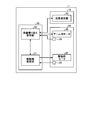
次いで、制御部30について図8を参照しつつ説明する。図8は、移動ロボット1の構成を示すブロック図である。
なお、図8では、本実施形態の説明にあたり必要な構成要素のみを示しており、一般的な構成要素についての記載を省略している。また、複数個の構成要素(例えば、駆動用モータ24やアーム用モータ26)については、図示の簡略化のため、1つのブロックにまとめて示すが、実際には複数個の構成要素が個別に制御されることは前述した通りである。
図8に示すように、移動ロボット1の制御部30は、移動ロボット1の動作を制御する制御装置であり、例えばコンピュータなどからなる。制御部30は、例えば図示しない上位コントローラ(もしくは操作者)から、移動本体部10の前進、後進、旋回、段差乗り越えなどの操作指令が入力され、入力された操作指令に応じて駆動用モータ24やアーム用モータ26などの動作を制御する。なお、制御部30は、上記した操作指令によらずに、前後進、旋回、段差乗り越えなどを行うように構成してもよい。
制御部30は具体的に、駆動輪制御部31と、段差乗り越え制御部32とを備える。駆動輪制御部31は、段差乗り越え制御部32と通信可能に接続されるとともに、駆動用モータ24のエンコーダ25のエンコーダ値などが入力される。駆動輪制御部31は、後述するように段差乗り越え制御部32から受け取った制御指令やエンコーダ25のエンコーダ値などに基づいて駆動用モータ24の動作を制御し、主車輪21および副車輪23を回転駆動させる。
段差乗り越え制御部32は、上位コントローラからの操作指令、具体的には段差乗り越え開始指令に応じて、自律的に段差乗り越え動作が実行されるように移動ロボット1の動作を制御する。
段差乗り越え制御部32には、段差検出部40の出力信号やアーム用モータ26のエンコーダ28のエンコーダ値が入力される。段差乗り越え制御部32は、入力された各種信号に基づき、アーム用モータ26の動作を制御し、アーム22を揺動させる。また、段差乗り越え制御部32は、段差乗り越え時において駆動輪制御部31へ制御指令を出力し、駆動用モータ24を介して主車輪21および副車輪23を回転駆動させる。
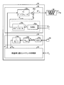
図9は、図8に示す段差乗り越え制御部32の構成を示すブロック図である。図9に示すように、段差乗り越え制御部32は、段差乗り越えシーケンス処理部33と、段差検出処理部34と、モータ制御部35とを備える。
段差乗り越えシーケンス処理部33は、段差乗り越え動作を自律的に実行するためのシーケンス処理を行う。具体的に段差乗り越えシーケンス処理部33は、駆動用モータ24の駆動情報(エンコーダ値など)および段差検出処理部34から得られる段差検出値SR,SL(後述)に基づき、アーム22の揺動角や駆動輪(主車輪21および副車輪23)に関する制御指令を出力する。この処理については後述する。
段差検出処理部34は、移動本体部10の左右に設けられた段差検出部40の出力から左右の段差検出値SR,SLを算出する処理を実行する。なお、上記した段差検出値SRは、右側の段差検出部40から算出された値であり、段差検出値SLは、左側の段差検出部40から算出された値である。
具体的に段差検出処理部34は、左右の段差検出部40の出力信号が入力されると、ADコンバータ34aを介して出力電圧AoutR,AoutLを得る。そして、段差検出処理部34では、出力電圧AoutR,AoutLを乗算器34b、フィルタ34cへ供給し、下記の式(7)のように左右の段差検出値SR,SLを算出する。なお、段差検出値SR,SLは段差乗り越えシーケンス処理部33へ入力され、そこで左右の段差検出値SR,SLから下記の式(8)を用いて段差Cの平均段差検出値(段差Cの高さ)Sを求める。


モータ制御部35の説明の前に、段差乗り越え制御部32の機能について説明すると、段差乗り越え制御部32では、アーム22の角度制御が主として行われる。アーム22への角度指令は、段差乗り越えシーケンス処理部33によって生成されるため、モータ制御部35は2次フィルタ35cを乗じた値をアーム用モータ26への位置指令として出力する。
なお、本実施形態に係る移動ロボット1の段差乗り越えでは、副車輪23の接地時における衝撃を軽減させるため、下記のような動作1,2が採られている。
(動作1):副車輪23の接地直前でアーム22の振り下げ速度を落とし、接地衝撃を緩和する。
(動作2):アドミッタンス制御を用いて柔軟制御し、接地衝撃を緩和する。
(動作1):副車輪23の接地直前でアーム22の振り下げ速度を落とし、接地衝撃を緩和する。
(動作2):アドミッタンス制御を用いて柔軟制御し、接地衝撃を緩和する。
モータ制御部35において、アドミッタンス制御に基づく位置指令補正量θcompxは、図9において破線で囲まれた、外力T^dxを推定する外乱オブザーバ(DOBS(Disturbance Observer))35aと、仮想的なマスバネダンパ系を模擬する2次フィルタ35bによって得られる。具体的には下記の式(9)にしたがって演算する。

したがって、アーム用モータ26への位置指令θ*
mxは、位置指令補正量θcompxと、段差乗り越えシーケンス処理部33からの位置指令θ*
xを2次フィルタ35cに供給して得た値とを、加算器35dにおいて加算して算出される。具体的に位置指令θ*
mxは、下記の式(10)を用いて演算される。なお、ここでの指令フィルタの設定は、例えば減衰係数ζが1.0、角周波数ωnが2πrad/s程度とされるが、これらは例示であって限定されるものではない。

そして、位置指令θ*
mxはアーム用モータ26側の位置速度制御部36へ供給され、そこでトルク指令T*
mxが算出され、算出されたトルク指令T*
mxに基づいてアーム用モータ26は駆動される。なお、上記した各式および後述する式における添字xは、前後左右のアーム22であることを示し、例えば右前、左前、右後、左後のアーム22の順で、θ*
xはθ*
fr,θ*
fl,θ*
br,θ*
blなどと置換することができるものとする。
以上を踏まえつつ、次いで、移動ロボット1の制御部30(正確には段差乗り越えシーケンス処理部33など)で実行される、移動ロボット1の段差乗り越え処理について説明する。
なお、以下では、移動ロボット1が段差Cを乗り越える場面を例に挙げて説明するが、段差Cを降りる場合についても使用する数式等は変化せず、段差Cや管理する距離の符号を反転することで対応することができる。
図10は、移動ロボット1の段差乗り越え処理手順を示すフローチャートである。図10に示すように、先ず制御部30は、段差乗り越え開始指令(以下「開始指令」という)が例えば上位コントローラから入力されたか否かを判定する(ステップS10)。
制御部30は、開始指令が入力されない場合(ステップS10,No)、ステップS10の処理を繰り返す。一方、制御部30は、開始指令が入力された場合(ステップS10,Yes)、続いて排他処理を実行する(ステップS11)。この排他処理とは、移動ロボット1において、段差Cを乗り越えるための制御が行われているときは、例えば非常停止指令以外の処理を受け付けないようにする処理である。
次いで、制御部30は、移動ロボット1が所定速度Vaで前進するように、駆動用モータ24の動作を制御する(ステップS12)。この所定速度Vaは、比較的低い値、例えば0.02m/sに設定される。したがって、ステップS12の処理では、移動ロボット1は比較的低速で走行させられることとなる。
なお、上記した所定速度Vaの具体的な値は、例示であって限定されるものではない。また、以下においても各種の値に関して具体的な数値を例として挙げることもあるが、それらはあくまでも例示であって限定されるものではない。
次いで、制御部30は、移動ロボット1の前進した距離P1がしきい値P1a未満か否かを判定する(ステップS13)。なお、ここでしきい値P1aは、移動ロボット1の大きさや用途、移動ロボット1が走行する場所などに基づいて適宜な値に設定され、ここでは例えば1mと設定される。
制御部30は、移動ロボット1の前進距離P1がしきい値P1a未満であると判定した場合(ステップS13,Yes)、続いて左右の段差検出部40のうちの少なくともいずれかで段差Cが検出されたか否かを判定する(ステップS14)。
ステップS14では、具体的には左右の段差検出値SR,SLのうちの少なくともいずれかがしきい値Saよりも大きいか否で段差Cの有無を判定し、具体的にしきい値Saよりも大きい場合、路面Bに段差Cがあると判定する。なお、しきい値Saは例えば0.01mとされる。
制御部30は、左右の段差検出部40のいずれでも段差Cが検出されない場合(ステップS14,No)、ステップS12の処理に戻って前進動作を続ける。また、制御部30は、左右の段差検出部40のいずれかで段差Cが検出された場合(ステップS14,Yes)、次いで移動ロボット1の位置補正・段差高さ取得処理を実行する(ステップS15)。
図11は、図10のステップS15の位置補正・段差高さ取得処理の概要を示すフローチャートである。
図11に示すように、制御部30は、先ず移動ロボット1を所定距離P2前進させ(ステップS100)、続いて左右の段差検出部40の両方で段差Cが検出されたか否かを判定する(ステップS101)。
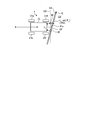
ここで、ステップS100の処理で使用される所定距離P2、およびステップS101の処理について、図12、図13A、図13Bを参照して詳しく説明する。図12、図13A、図13Bは、移動ロボット1の模式平面図である。なお、図12などでは、図の簡略化のため、アーム22や副車輪23などの図示を省略した。
先ず図12において、Lsは、左右の段差検出部40の離間距離を表し、θaは、移動本体部10の前面10fに対して平行な直線10f1と、段差Cの側壁面C2とのなす角度を表す。
図12のθaは、例えば移動ロボット1が段差Cの側壁面C2に対して傾いているが、そのままの状態であっても移動ロボット1は段差Cを乗り越えることができる角度の上限値とされる。すなわち、θaは移動ロボット1の段差Cに対する許容角度である。
所定距離P2は、上記した離間距離Lsと許容角度θaとを用いた、Lssin(θa)によって求められる(図12参照)。
ここでは、ステップS14で左右の段差検出部40のいずれか一方で段差Cが検出された後、ステップS100で移動ロボット1を所定距離P2だけ前進させ、そしてステップS101で左右の段差検出部40の両方で段差Cが検出されたか否かを判定している。
すなわち、図13Aに示すように、移動ロボット1が所定距離P2進んだにもかかわらず、左右の段差検出部40の両方で段差Cが検出されない場合、移動ロボット1は、側壁面C2に対して許容角度θaを超えて傾いている状態にある。したがって、後述するように、移動本体部10の向きを補正するようにする。
他方、図13Bに示すように、移動ロボット1が所定距離P2進んだときに、左右の段差検出部40の両方で段差Cが検出される場合、移動ロボット1の側壁面C2に対する角度は許容角度θaの範囲内である。したがって、移動本体部10の向きの補正を行わず、そのまま段差乗り越え動作に移行するようにする。
図11の説明に戻る。制御部30は、左右の段差検出部40の両方で段差Cが検出されない場合(ステップS101,No)、正確には左右の段差検出部40のうちの一方で段差Cが検出され、他方で段差Cが検出されない場合、ステップS102以降で移動本体部10の向きを補正する。詳しくは、ステップS102以降では、移動本体部10が段差Cの側壁面C2と正対するように移動本体部10の向きを補正する。
具体的に制御部30は、移動ロボット1が所定角速度γで信地旋回動作するように、駆動用モータ24の動作を制御、具体的には主車輪21の動作を制御する(ステップS102)。
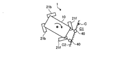
この信地旋回動作について、図14Aから図14Cを参照して説明する。図14Aから図14Cは、移動ロボット1の模式平面図である。
図14Aでは、例えば左右の段差検出部40のうち、右側の段差検出部40で段差Cが検出され、左側の段差検出部40で段差Cが検出されない場面が示されている。以下、この場面を例にとって説明する。
この場合、制御部30は、左右の主車輪21のうち段差Cが検出されていない側の主車輪21、すなわち、左側の主車輪21を移動本体部10が前進する方向へ回転するように、駆動用モータ24の動作を制御する。なお、このときの右側の主車輪21は停止している。これにより、左側の段差検出部40は、段差Cへ向けて徐々に近づけられることとなる。
なお、図14Aなどでは、信地旋回動作を理解し易くするため、主車輪21の向きを変えて示したが、例えば実際に主車輪21を操舵する機構を設け、同図のように、主車輪21の向きを変えながら信地旋回動作を行うようにしてもよい。
また、上記では、段差Cが検出されていない左側の主車輪21を前進方向へ回転させるようにしたが、これに限定されるものではなく、段差Cが検出された右側の主車輪21を、後進方向へ回転させて、信地旋回動作を行ってもよい。さらには、左右の主車輪21で、回転方向を相違させる、いわゆる超信地旋回であってよい。
図11の説明に戻ると、制御部30は、信地旋回による旋回角度Pγがしきい値Pγa未満か否かを判定する(ステップS103)。このしきい値Pγaは、例えば45degとされる。
制御部30は、旋回角度Pγがしきい値Pγa未満の場合(ステップS103,Yes)、続いて、最初に段差Cを検出していない段差検出部40、ここでは左側の段差検出部40で段差Cが検出されたか否かを判定する(ステップS104)。具体的にステップS104は、移動本体部10が図14Bに示すような状態になったか否かを判定する処理である。
制御部30は、左側の段差検出部40で段差Cが検出されない場合(ステップS104,No)、ステップS102の処理に戻る。他方、制御部30は、左側の段差検出部40で段差が検出された場合(ステップS104,Yes)、今度はステップS102での旋回方向とは反対側の方向へ所定旋回角度Rγだけ信地旋回動作を行う(ステップS105)。具体的にこの場合の制御部30は、例えば右側の主車輪21を移動本体部10が前進する方向へ回転するように、駆動用モータ24の動作を制御する。
また、所定旋回角度Rγは、ステップS102の処理を最初に実行してからステップS104で肯定されるまでに旋回した旋回角度Pγよりも小さい値、例えば旋回角度Pγの半分程度とされる。
このように、制御部30は、移動本体部10を反対方向へ少し戻すように旋回させて、図14Bに示す状態だった移動本体部10を、図14Cに示すような、段差Cの側壁面C2と正対した状態にする。このように、ステップS102~S105の処理では、移動本体部10が段差Cの側壁面C2と正対するように移動本体部10の向きを補正する。これにより、後述する段差Cの乗り越え動作において、移動ロボット1は確実に段差Cを乗り越えることができる。
また、上記のように、移動本体部10を信地旋回させて移動本体部10の向きを補正することから、移動本体部10において側壁面C2と正対させるときの動作範囲を小さくすることができる。
なお、制御部30は、旋回角度Pγがしきい値Pγa以上となった場合(ステップS103,No)、そこまで旋回して段差検出部40で段差Cが検出されないときには何らかの異常が発生したと判定して、そのまま図10のフローチャートへ戻る。
制御部30は、移動本体部10の向きを補正した後、移動ロボット1が所定速度Vaで前進するように、駆動用モータ24の動作を制御する(ステップS106)。
次いで、制御部30は、ステップS106の処理によって移動ロボット1の前進した距離P3がしきい値P3a未満か否かを判定する(ステップS107)。なお、しきい値P3aは例えば10cmと設定される。
制御部30は、移動ロボット1の前進距離P3がしきい値P3a未満である場合(ステップS107,Yes)、次いで段差検出部40の両方で段差Cが検出されたか否かを判定する(ステップS108)。
制御部30は、左右の段差検出部40の両方で段差Cが検出されない場合(ステップS108,No)、ステップS106の処理に戻る。なお、制御部30は、前進距離P3がしきい値P3a以上となった場合(ステップS107,No)、そこまで前進して段差検出部40で段差Cが検出されないときには何らかの異常が発生したと判定して、そのまま図10のフローチャートへ戻る。
制御部30は、左右の段差検出部40の両方で段差Cが検出された場合(ステップS108,No)、続いて、検出された段差Cの高さS、正確には平均段差検出値Sを取得する(ステップS109)。これについては、前述した式(8)を用いて算出する。
次いで、制御部30は、主車輪21の動作を制御し、前副車輪23fが段差Cの所定位置に接地するように移動本体部10の位置を調整する(ステップS110)。
図15は、その移動本体部10の位置の調整を説明するための移動ロボット1の模式側面図である。
図15に示すように、段差検出部40で段差Cを検出した後、前副車輪23fを段差Cの段差面C1の所定位置に接地させるため、移動本体部10を前進もしくは後退させる必要がある。なお、この所定位置とは、前副車輪23fが段差面C1において確実に、かつ安定して乗ることができるような位置を意味する。
ここでは、例えば移動本体部10を後退距離x2後退させて、前副車輪23fを段差Cの段差面C1の所定位置に接地させるものとする。後退距離x2は、側面視において段差Cの段差面C1から前副車輪23fの下端23f1までのZ軸方向における距離をα、側面視において段差Cの側壁面C2から前副車輪23の下端23f1までのX軸方向における距離をβと定義すると、下記の式(11)から得られる。また、式(11)中にあるアーム22の終端位置θ*
fnは、下記の式(12)から得られる。


具体的には、式(12)によって求めた終端位置θ*
fnを式(11)に代入することによって、後退距離x2を得ることができる。なお、このθ*
fnは後に、アーム22を振り下げるときの終端位置θ*
fnとして利用する。
そして、制御部30は、移動本体部10が算出された後退距離x2だけ移動するように、駆動用モータ24を介して主車輪21の動作を制御する。これにより、前副車輪23fを段差Cの段差面C1に確実かつ安定して乗せることができる。
制御部30は、次いで位置補正が正常に終了したことを示すフラグを立てて(ステップS111)、図10のフローチャートへ戻る。なお、ステップS101で左右の段差検出部40の両方で段差Cが検出された場合(ステップS101,Yes)、移動ロボット1は図13Bに示す状態であるため、位置補正することなくステップS111へ進んで、上記した処理を行う。
図10の説明に戻ると、制御部30は、位置補正が正常に終了したか否かを判定、すなわち、上記したフラグが立っているか否かを判定する(ステップS16)。制御部30は、位置補正が正常に終了している場合(ステップS16,Yes)、次いでアーム振り下げ処理を実行する(ステップS17)。
図16は、そのアーム振り下げ処理の概要を示すフローチャートである。
図16に示すように、制御部30は、先ずアーム22の振り下げ速度ωmax1を設定する(ステップS200)。ここでは振り下げ速度ωmax1は比較的高い値、例えば30deg/sに設定される。
制御部30は、次いで前後のアーム22を、ステップS200で設定された振り下げ速度ωmax1で終端位置θ*
fnまで振り下げるように揺動させる(ステップS201)。終端位置θ*
fnは、上記した式(12)によって得られる。
したがって、図15に示すように、例えば前アーム22fは、実線で示される初期位置から想像線で示される終端位置θ*
fnまで、比較的高速で振り下げられることとなる。また、後アーム22bも、前アーム22fと同様、初期位置から、想像線で示す終端位置θ*
bnまで比較的高速で振り下げられる。なお、終端位置θ*
fnと終端位置θ*
bnとは、同じ値とされる。
次いで、制御部30は、アーム22の振り下げ速度ωmax2を設定する(ステップS202)。ここで振り下げ速度ωmax2は、ステップS200で設定した値よりも低い値、例えば10deg/sに設定される。
制御部30は、前アーム22fを、ステップS202で設定された振り下げ速度ωmax2で終端位置θ*
fe(後述)まで振り下げるように揺動させる(ステップS203)。
図17は、そのときの移動ロボット1を示す模式側面図である。図17に示すように、ステップ203の処理によって、前副車輪23fが路面Bに接地、正確には段差Cの段差面C1に接地される。
次いで、制御部30は、後アーム22bを、ステップS202で設定された振り下げ速度ωmax2で終端位置θ*
be(後述)まで、前アーム22fと同期させつつ振り下げるように揺動させる(ステップS204)。これにより、後副車輪23bが路面Bに接地される。
このように、路面Bから離間した位置、すなわち初期位置にある副車輪23を路面Bに接地させる場合、副車輪23が路面Bに接地する直前にアーム22の動作速度を減速させる。これにより、副車輪23が路面Bに接地する際に、移動ロボット1に作用する衝撃を軽減することができる。
次いで、制御部30は、後副車輪23bを前後アーム22f,22bに同期させつつ移動させる(ステップS205)。
上記したステップS203~S205の一連の処理について、図18を参照して詳説する。図18は、ステップS203~S205の処理を説明するための、移動ロボット1を示す模式側面図である。
まず、本実施形態に係る移動ロボット1にあっては、段差Cを乗り越える場合、移動本体部10を所定の姿勢、例えば水平を維持しつつ乗り越えるように、前アーム22fと後アーム22bとを協働させて動作させるようにする。この移動本体部10を水平に維持するため条件は、下記の式(13)によって表される。

したがって、図18に示すように、移動本体部10を水平に維持するための後アーム22bの制御角指令は、前アーム22fの角度を基準とすると、以下の式(14)によって算出される。

また、前輪21fと後輪21bとはともに、サーボロックされているため、アーム22の揺動に合わせて主車輪21の位置を協調制御する必要がある。段差Cに掛かる前輪21fをサーボロックし、後輪21bの位置で調整することを考え、段差Cと前副車輪23fが接触した角度を近似的にθ*
fn, θ*
bnとみなし、その後の副車輪23bの移動量を式(15)によって求める。

また、アーム揺動の終端位置θ*
fe, θ*
beは、主車輪21の接地点が段差Cを越えればよいため、マージンδを見込んで式(16)、式(17)で算出される。なお、この終端位置θ*
fe, θ*
beが、ステップS203,S204で使用される。
アドミッタンス制御を用いているため、自重によって位置指令と終端位置に誤差が生じるが、仮想的に設定したバネダンパの特性に応じてマージンδを調整すればよい。


このように、制御部30は、移動本体部10を所定の姿勢、例えば水平を維持しつつ乗り越えるように、前後アーム22f,22bを協働させて動作させるようにした。
これにより、移動ロボット1は、段差Cを乗り越える際に重心のバランスも維持されることから、横転などすることはなく、段差Cを確実に乗り越えることができる。また、例えば移動ロボット1が物を運搬する用途で用いられる場合、段差Cを乗り越えるときに移動本体部10の姿勢を水平に維持することで、物が落下するのを防止することができる。
また、前後アーム22f,22bを協働させることで、移動本体部10が持ち上がるときに移動本体部10からアーム22へ作用する負荷を分散させることができ、アーム22やアーム用モータ26を小型化することもできる。
なお、移動本体部10の所定の姿勢は、水平に限定されるものではなく、例えば移動本体部10を前方または後方に傾斜するような姿勢でもよく、あるいは左側または右側に傾斜するようにしてもよい。
図10の説明に戻ると、制御部30は次いで移動ロボット1を所定速度Vaで所定距離P4前進させる(ステップS18)。所定距離P4は、例えば進行方向Aにおける移動ロボット1の長さ(全長)と同程度の値に設定される。
図19は、所定距離P4前進した後の移動ロボット1を示す模式側面図である。図19に示すように、ステップS18の処理によって移動ロボット1は、前輪21fおよび後輪21bがともに、段差Cの段差面C1のところまで移動された状態とされる。
なお、移動ロボット1にあっては、上記したマージンδを見込むようにしたことから、図19に示すように、主車輪21は段差Cの段差面C1から離れているが、例えばマージンδをゼロに設定し、主車輪21が段差面C1に接地するようにしてもよい。これにより、移動ロボット1は、主車輪21と副車輪23との両方の回転駆動によって所定距離P4前進することができ、段差Cを乗り越えるのに要する時間を短縮することもできる。
制御部30は、次いでアーム振り上げ処理を実行する(ステップS19)。図20は、そのアーム振り上げ処理の概要を示すフローチャートである。
図20に示すように、制御部30は、アーム22の振り上げ速度ωmax3を設定する(ステップS300)。ここでは振り上げ速度ωmax3は、比較的低い値、例えば10deg/sに設定される。
制御部30は、前アーム22fを、ステップS300で設定された振り上げ速度ωmax3で終端位置θ*
fp(後述)まで振り上げるように揺動させる(ステップS301)。
図21は、そのときの移動ロボット1を示す模式側面図である。図21に示すように、ステップ301の処理によって、前副車輪23fが路面Bから所定距離(マージンδ)離反される。
次いで、制御部30は、後アーム22bを、ステップS300で設定された振り上げ速度ωmax3で終端位置θ*
bp(後述)まで、前アーム22fと同期させつつ振り上げるように揺動させる(ステップS302)。これにより、図21に示す如く、後副車輪23bも路面Bから離反される。
次いで、制御部30は、後副車輪23bを前後アーム22f,22bに同期させつつ移動させる(ステップS303)。
上記したステップS300~S303の一連の処理について詳説する。図21に示すように、移動ロボット1が段差Cを乗り越えた後、式(16)においてS=0かつδ<0とすると、移動本体部10が着地して副車輪23が路面Bから所定距離(マージンδ)だけ浮上した状態に制御することができる。
よって、このときのアーム22の終端位置θ*
fp,θ*
bpは、下記の式(18)、(19)を用いて算出され、ステップS301,S302で使用される。また、上記したようにアーム振り上げ時は、終端位置θ*
fp,θ*
bpになるまでアーム22を低速で動作させる。


また、ステップS303において、振り上げ時の後副車輪23bの移動量dPosxbについても、振り下げ時の式(15)と同様に考え、下記の式(20)を用いて算出するようにする。

図20の説明に戻ると、次いで、制御部30は、アーム22の振り上げ速度ωmax4を設定する(ステップS304)。ここで振り上げ速度ωmax4は、ステップS300で設定した値よりも高い値、例えば30deg/sに設定される。
次いで、制御部30は、図21に想像線で示すように、前後アーム22f,22bを、ステップS304で設定された振り上げ速度ωmax4で終端位置θ*
initまで振り上げるように揺動させる(ステップS305)。すなわち、ステップS305の処理によって、アーム22および副車輪23が初期位置まで戻される。
このようにアーム22を動作させて、路面Bに接地される副車輪23を路面Bから離反させて初期位置へ戻す場合、副車輪23が路面Bから所定距離δ離反するまでのアーム22の動作速度(振り上げ速度ωmax3)が、副車輪23が所定距離δ離反してから初期位置へ戻るまでのアーム22の動作速度(振り上げ速度ωmax4)よりも低くなるようにした。
これにより、副車輪23は比較的低速で路面Bから離反することから、主車輪21が路面Bに接地するときに、移動ロボット1が路面Bから受ける衝撃を軽減することができる。
図10の説明に戻ると、制御部30は、排他処理を解除する(ステップS20)。これにより、移動ロボット1は段差乗り越え制御から通常制御へ切り替えられる。このようにして、移動ロボット1の段差乗り越え動作が終了する。
なお、制御部30は、ステップS13において移動ロボット1の前進した距離P1がしきい値P1a以上になった場合(ステップS13,No)、移動ロボット1の付近に段差Cがない、あるいは何らかの異常が発生したと判定してステップS20の処理後、プログラムを終了する。
また、制御部30は、ステップS16において位置補正が正常に終了していないと判定した場合(ステップS16,No)、同様に、何らかの異常が発生したと判定してステップS20の処理後、プログラムを終了する。
上述してきたように、本実施形態では、主車輪21は、移動本体部10に回転可能に取り付けられる。アーム22は、移動本体部10に揺動可能に取付けられ、揺動中心軸22cが主車輪21の回転中心軸21cに対してオフセットされる。副車輪23は、アーム22の先端部22dに回転可能に取り付けられる。制御部30は、路面Bの状態に応じてアーム22の動作を制御し、副車輪23を路面Bに接地させる。これにより、移動ロボット(移動体)1において、走行効率を維持しつつ、小型でかつ簡素な構成で路面Bの段差Cを乗り越えることができる。
なお、上述した実施形態では、移動本体部10の前後にアーム22および副車輪23をそれぞれ取り付けるように構成したが、これに限定されるものではなく、例えば移動本体部10の前側にのみアーム22および副車輪23を取り付けるようにしてもよい。
また、主車輪21および副車輪23はともに駆動用モータ24で駆動されるようにしたが、これに限定されるものでなない。すなわち、主車輪21および副車輪23のそれぞれに別の駆動源が接続され、独立に駆動されるように構成してもよい。これにより、例えば移動ロボット1が段差Cを昇降する場合に限って、副車輪23を回転駆動させるようにすることができる。また、駆動源にあっては、対応する主車輪21または副車輪23のみを駆動できればよいことから、小型化することもできる。
また、主車輪21などの駆動源として、移動本体部10に収納された駆動用モータ24を例に挙げて説明したが、例えばインホイールモータなどその他の駆動源であってもよく、さらには例えば内燃機関などであってもよい。
また、上記では、移動体が移動ロボット1であるものとして説明したが、これに限定されるものではなく、例えば自動車や二輪車など移動するような構成であれば、どのようなものであってもよい。
さらなる効果や変形例は、当業者によって容易に導き出すことができる。このため、本発明のより広範な態様は、以上のように表しかつ記述した特定の詳細および代表的な実施形態に限定されるものではない。したがって、添付の特許請求の範囲およびその均等物によって定義される総括的な発明の概念の精神または範囲から逸脱することなく、様々な変更が可能である。
1 移動ロボット(移動体)
10 移動本体部
20 移動部
21 主車輪
21c (主車輪の)回転中心軸
22 アーム
22c (アームの)揺動中心軸
23 副車輪
24 駆動用モータ(駆動源)
26 アーム用モータ
30 制御部
40 段差検出部
B 路面
C 段差
C1 段差面
C2 側壁面
10 移動本体部
20 移動部
21 主車輪
21c (主車輪の)回転中心軸
22 アーム
22c (アームの)揺動中心軸
23 副車輪
24 駆動用モータ(駆動源)
26 アーム用モータ
30 制御部
40 段差検出部
B 路面
C 段差
C1 段差面
C2 側壁面
Claims (9)
- 移動本体部に回転可能に取り付けられる主車輪と、
前記移動本体部に揺動可能に取付けられ、揺動中心軸が前記主車輪の回転中心軸に対してオフセットされるアームと、
前記アームの先端部に回転可能に取り付けられる副車輪と、
路面の状態に応じて前記アームの動作を制御し、前記副車輪を路面に接地させる制御部と
を備えることを特徴とする移動体。 - 前記アームの揺動中心軸は、
前記主車輪の回転中心軸よりも鉛直方向において下方にオフセットされること
を特徴とする請求項1に記載の移動体。 - 前記主車輪および前記副車輪の両方に接続され、前記主車輪および前記副車輪を駆動する駆動源
を備えることを特徴とする請求項1に記載の移動体。 - 前記アームは、
進行方向において前記移動本体部の前後にそれぞれ取り付けられ、
前記制御部は、
路面の段差を昇降する場合、前記移動本体部が所定の姿勢を維持するように、前記移動本体部の前側の前記アームと、前記移動本体部の後側の前記アームとを協働させて動作させること
を特徴とする請求項1に記載の移動体。 - 進行方向において前記移動本体部の前方の左右側にそれぞれ取り付けられ、路面の段差を検出する段差検出部
を備え、
前記制御部は、
前記左右の段差検出部のうちの一方で段差が検出され、他方で段差が検出されない場合、前記主車輪の動作を制御し、前記移動本体部が段差の側壁面と正対するように前記移動本体部の向きを補正すること
を特徴とする請求項1に記載の移動体。 - 前記制御部は、
前記移動本体部を信地旋回させて前記移動本体部の向きを補正すること
を特徴とする請求項5に記載の移動体。 - 前記制御部は、
前記アームを動作させて、路面から離間した位置にある前記副車輪を路面に接地させる場合、前記副車輪が路面に接地する直前に前記アームの動作速度を減速させること
を特徴とする請求項1に記載の移動体。 - 前記制御部は、
前記アームを動作させて、路面に接地される前記副車輪を路面から離反させて初期位置へ戻す場合、前記副車輪が路面から所定距離離反するまでの前記アームの動作速度が、前記副車輪が前記所定距離離反してから前記初期位置へ戻るまでの前記アームの動作速度よりも低くなるようにすること
を特徴とする請求項1に記載の移動体。 - 前記移動本体部に取り付けられ、路面の段差を検出する段差検出部
を備え、
前記制御部は、
前記段差検出部によって段差が検出された場合、前記主車輪の動作を制御し、前記副車輪が段差の所定位置に接地するように前記移動本体部の位置を調整すること
を特徴とする請求項1~8のいずれか一つに記載の移動体。
Priority Applications (2)
| Application Number | Priority Date | Filing Date | Title |
|---|---|---|---|
| PCT/JP2013/060532 WO2014162605A1 (ja) | 2013-04-05 | 2013-04-05 | 移動体 |
| JP2015509849A JPWO2014162605A1 (ja) | 2013-04-05 | 2013-04-05 | 移動体 |
Applications Claiming Priority (1)
| Application Number | Priority Date | Filing Date | Title |
|---|---|---|---|
| PCT/JP2013/060532 WO2014162605A1 (ja) | 2013-04-05 | 2013-04-05 | 移動体 |
Publications (1)
| Publication Number | Publication Date |
|---|---|
| WO2014162605A1 true WO2014162605A1 (ja) | 2014-10-09 |
Family
ID=51657930
Family Applications (1)
| Application Number | Title | Priority Date | Filing Date |
|---|---|---|---|
| PCT/JP2013/060532 Ceased WO2014162605A1 (ja) | 2013-04-05 | 2013-04-05 | 移動体 |
Country Status (2)
| Country | Link |
|---|---|
| JP (1) | JPWO2014162605A1 (ja) |
| WO (1) | WO2014162605A1 (ja) |
Cited By (10)
| Publication number | Priority date | Publication date | Assignee | Title |
|---|---|---|---|---|
| JP2017003383A (ja) * | 2015-06-09 | 2017-01-05 | 三菱電機株式会社 | 段差検出装置及び段差乗り越え装置 |
| CN107458489A (zh) * | 2016-06-02 | 2017-12-12 | 松下知识产权经营株式会社 | 移动机器人 |
| JP2019085064A (ja) * | 2017-11-10 | 2019-06-06 | 株式会社ネットプラザ栃木 | 走行装置 |
| EP3508403A4 (en) * | 2016-08-30 | 2019-10-02 | Lu, Renhang | MULTILING INDEPENDENT MOBILE CARRIER |
| US11148696B2 (en) | 2018-12-27 | 2021-10-19 | Toyota Research Institute, Inc. | Assistive robots including assemblies for accommodating obstacles and methods for using the same |
| US11420338B2 (en) | 2018-12-27 | 2022-08-23 | Toyota Research Institute, Inc. | Assistive robot systems for container tilting |
| US11505017B2 (en) | 2018-12-27 | 2022-11-22 | Toyota Research Institute, Inc. | Devices including deployable hitch assemblies and autonomous engagement systems incorporating the same |
| JP2023044065A (ja) * | 2021-09-17 | 2023-03-30 | 株式会社ダイヘン | 移動体 |
| US11827500B2 (en) | 2018-12-27 | 2023-11-28 | Toyota Research Institute, Inc. | Assistive robot systems for transporting containers |
| US12605822B2 (en) * | 2021-01-28 | 2026-04-21 | Samsung Electronics Co., Ltd. | Mobile robot apparatus and control method therefor |
Citations (6)
| Publication number | Priority date | Publication date | Assignee | Title |
|---|---|---|---|---|
| JPS63170179A (ja) * | 1987-01-06 | 1988-07-14 | Toshiba Corp | 移動体 |
| JPH10236350A (ja) * | 1997-02-28 | 1998-09-08 | Nippon Signal Co Ltd:The | 階段昇降装置 |
| JP2006190105A (ja) * | 2005-01-06 | 2006-07-20 | Toshiba Corp | 移動ロボット |
| JP2009298208A (ja) * | 2008-06-11 | 2009-12-24 | Panasonic Corp | 車輪型走行装置 |
| JP2010006247A (ja) * | 2008-06-27 | 2010-01-14 | Panasonic Corp | 脚車輪装置およびそれを用いた走行装置 |
| JP2010030523A (ja) * | 2008-07-30 | 2010-02-12 | Toyota Motor Corp | 二輪自動車 |
-
2013
- 2013-04-05 WO PCT/JP2013/060532 patent/WO2014162605A1/ja not_active Ceased
- 2013-04-05 JP JP2015509849A patent/JPWO2014162605A1/ja active Pending
Patent Citations (6)
| Publication number | Priority date | Publication date | Assignee | Title |
|---|---|---|---|---|
| JPS63170179A (ja) * | 1987-01-06 | 1988-07-14 | Toshiba Corp | 移動体 |
| JPH10236350A (ja) * | 1997-02-28 | 1998-09-08 | Nippon Signal Co Ltd:The | 階段昇降装置 |
| JP2006190105A (ja) * | 2005-01-06 | 2006-07-20 | Toshiba Corp | 移動ロボット |
| JP2009298208A (ja) * | 2008-06-11 | 2009-12-24 | Panasonic Corp | 車輪型走行装置 |
| JP2010006247A (ja) * | 2008-06-27 | 2010-01-14 | Panasonic Corp | 脚車輪装置およびそれを用いた走行装置 |
| JP2010030523A (ja) * | 2008-07-30 | 2010-02-12 | Toyota Motor Corp | 二輪自動車 |
Cited By (13)
| Publication number | Priority date | Publication date | Assignee | Title |
|---|---|---|---|---|
| JP2017003383A (ja) * | 2015-06-09 | 2017-01-05 | 三菱電機株式会社 | 段差検出装置及び段差乗り越え装置 |
| CN107458489A (zh) * | 2016-06-02 | 2017-12-12 | 松下知识产权经营株式会社 | 移动机器人 |
| CN107458489B (zh) * | 2016-06-02 | 2021-06-29 | 松下知识产权经营株式会社 | 移动机器人 |
| EP3508403A4 (en) * | 2016-08-30 | 2019-10-02 | Lu, Renhang | MULTILING INDEPENDENT MOBILE CARRIER |
| JP2019085064A (ja) * | 2017-11-10 | 2019-06-06 | 株式会社ネットプラザ栃木 | 走行装置 |
| US11420338B2 (en) | 2018-12-27 | 2022-08-23 | Toyota Research Institute, Inc. | Assistive robot systems for container tilting |
| US11148696B2 (en) | 2018-12-27 | 2021-10-19 | Toyota Research Institute, Inc. | Assistive robots including assemblies for accommodating obstacles and methods for using the same |
| US11505017B2 (en) | 2018-12-27 | 2022-11-22 | Toyota Research Institute, Inc. | Devices including deployable hitch assemblies and autonomous engagement systems incorporating the same |
| US11597098B2 (en) | 2018-12-27 | 2023-03-07 | Toyota Research Institute, Inc. | Assistive robot systems for container lifting |
| US11827500B2 (en) | 2018-12-27 | 2023-11-28 | Toyota Research Institute, Inc. | Assistive robot systems for transporting containers |
| US12605822B2 (en) * | 2021-01-28 | 2026-04-21 | Samsung Electronics Co., Ltd. | Mobile robot apparatus and control method therefor |
| JP2023044065A (ja) * | 2021-09-17 | 2023-03-30 | 株式会社ダイヘン | 移動体 |
| JP7732820B2 (ja) | 2021-09-17 | 2025-09-02 | 株式会社ダイヘン | 移動体 |
Also Published As
| Publication number | Publication date |
|---|---|
| JPWO2014162605A1 (ja) | 2017-02-16 |
Similar Documents
| Publication | Publication Date | Title |
|---|---|---|
| WO2014162605A1 (ja) | 移動体 | |
| JP3791663B2 (ja) | 全方向移動車両とその制御方法 | |
| US9586636B1 (en) | Multi-segmented magnetic robot | |
| WO2014002275A1 (ja) | 移動体および移動体システム | |
| JP6332018B2 (ja) | 搬送ロボット、及びその制御方法 | |
| CN107783540A (zh) | 一种四轮驱动转向的控制方法及装置 | |
| US11975787B2 (en) | Control device for mobile body | |
| CN111506054B (zh) | 一种4wid-4wis机器人底盘的自动导引方法 | |
| JP6837910B2 (ja) | 全方向移動車両 | |
| WO2016143581A1 (ja) | 球乗りロボット | |
| CN107618614B (zh) | 一种二轮单轨车辆及其平衡的控制方法 | |
| KR20130099672A (ko) | 퍼지 추론 시스템 및 그 방법 | |
| JP5578738B2 (ja) | 車 | |
| WO2021155465A1 (en) | Inclination control system for tracked vehicle | |
| JP5907037B2 (ja) | 移動体 | |
| WO2017116873A1 (en) | Automatic balancing variable configuration articulated tracked transporter | |
| US20130282237A1 (en) | Inverted pendulum type moving body | |
| JP5913001B2 (ja) | 移動体制御装置、その制御方法、及び制御プログラム | |
| CN107444902A (zh) | 一种具有自动抓取功能的无人搬运车 | |
| CN205207531U (zh) | 差速驱动总成 | |
| CN113111443A (zh) | 智能运输小车及运动模型构建方法 | |
| JP2022190425A (ja) | 自走装置および自走装置の走行システム | |
| JP2008023700A (ja) | 脚型ロボットの力センサ設置構造 | |
| US20210041866A1 (en) | Accompanying control of locomotion device | |
| JP2011173453A (ja) | 車両の走行制御システム |
Legal Events
| Date | Code | Title | Description |
|---|---|---|---|
| 121 | Ep: the epo has been informed by wipo that ep was designated in this application |
Ref document number: 13881430 Country of ref document: EP Kind code of ref document: A1 |
|
| ENP | Entry into the national phase |
Ref document number: 2015509849 Country of ref document: JP Kind code of ref document: A |
|
| NENP | Non-entry into the national phase |
Ref country code: DE |
|
| 122 | Ep: pct application non-entry in european phase |
Ref document number: 13881430 Country of ref document: EP Kind code of ref document: A1 |