WO2014157629A1 - 回転電機駆動装置 - Google Patents
回転電機駆動装置 Download PDFInfo
- Publication number
- WO2014157629A1 WO2014157629A1 PCT/JP2014/059145 JP2014059145W WO2014157629A1 WO 2014157629 A1 WO2014157629 A1 WO 2014157629A1 JP 2014059145 W JP2014059145 W JP 2014059145W WO 2014157629 A1 WO2014157629 A1 WO 2014157629A1
- Authority
- WO
- WIPO (PCT)
- Prior art keywords
- inverter
- rotating electrical
- frequency
- electrical machine
- switching frequency
- Prior art date
- Legal status (The legal status is an assumption and is not a legal conclusion. Google has not performed a legal analysis and makes no representation as to the accuracy of the status listed.)
- Ceased
Links
Images




Classifications
-
- H—ELECTRICITY
- H02—GENERATION; CONVERSION OR DISTRIBUTION OF ELECTRIC POWER
- H02P—CONTROL OR REGULATION OF ELECTRIC MOTORS, ELECTRIC GENERATORS OR DYNAMO-ELECTRIC CONVERTERS; CONTROLLING TRANSFORMERS, REACTORS OR CHOKE COILS
- H02P27/00—Arrangements or methods for the control of AC motors characterised by the kind of supply voltage
- H02P27/04—Arrangements or methods for the control of AC motors characterised by the kind of supply voltage using variable-frequency supply voltage, e.g. inverter or converter supply voltage
- H02P27/06—Arrangements or methods for the control of AC motors characterised by the kind of supply voltage using variable-frequency supply voltage, e.g. inverter or converter supply voltage using DC to AC converters or inverters
- H02P27/08—Arrangements or methods for the control of AC motors characterised by the kind of supply voltage using variable-frequency supply voltage, e.g. inverter or converter supply voltage using DC to AC converters or inverters with pulse width modulation
- H02P27/085—Arrangements or methods for the control of AC motors characterised by the kind of supply voltage using variable-frequency supply voltage, e.g. inverter or converter supply voltage using DC to AC converters or inverters with pulse width modulation wherein the PWM mode is adapted on the running conditions of the motor, e.g. the switching frequency
-
- B—PERFORMING OPERATIONS; TRANSPORTING
- B60—VEHICLES IN GENERAL
- B60L—PROPULSION OF ELECTRICALLY-PROPELLED VEHICLES; SUPPLYING ELECTRIC POWER FOR AUXILIARY EQUIPMENT OF ELECTRICALLY-PROPELLED VEHICLES; ELECTRODYNAMIC BRAKE SYSTEMS FOR VEHICLES IN GENERAL; MAGNETIC SUSPENSION OR LEVITATION FOR VEHICLES; MONITORING OPERATING VARIABLES OF ELECTRICALLY-PROPELLED VEHICLES; ELECTRIC SAFETY DEVICES FOR ELECTRICALLY-PROPELLED VEHICLES
- B60L1/00—Supplying electric power to auxiliary equipment of vehicles
-
- B—PERFORMING OPERATIONS; TRANSPORTING
- B60—VEHICLES IN GENERAL
- B60L—PROPULSION OF ELECTRICALLY-PROPELLED VEHICLES; SUPPLYING ELECTRIC POWER FOR AUXILIARY EQUIPMENT OF ELECTRICALLY-PROPELLED VEHICLES; ELECTRODYNAMIC BRAKE SYSTEMS FOR VEHICLES IN GENERAL; MAGNETIC SUSPENSION OR LEVITATION FOR VEHICLES; MONITORING OPERATING VARIABLES OF ELECTRICALLY-PROPELLED VEHICLES; ELECTRIC SAFETY DEVICES FOR ELECTRICALLY-PROPELLED VEHICLES
- B60L15/00—Methods, circuits, or devices for controlling the traction-motor speed of electrically-propelled vehicles
- B60L15/007—Physical arrangements or structures of drive train converters specially adapted for the propulsion motors of electric vehicles
-
- B—PERFORMING OPERATIONS; TRANSPORTING
- B60—VEHICLES IN GENERAL
- B60L—PROPULSION OF ELECTRICALLY-PROPELLED VEHICLES; SUPPLYING ELECTRIC POWER FOR AUXILIARY EQUIPMENT OF ELECTRICALLY-PROPELLED VEHICLES; ELECTRODYNAMIC BRAKE SYSTEMS FOR VEHICLES IN GENERAL; MAGNETIC SUSPENSION OR LEVITATION FOR VEHICLES; MONITORING OPERATING VARIABLES OF ELECTRICALLY-PROPELLED VEHICLES; ELECTRIC SAFETY DEVICES FOR ELECTRICALLY-PROPELLED VEHICLES
- B60L58/00—Methods or circuit arrangements for monitoring or controlling batteries or fuel cells, specially adapted for electric vehicles
- B60L58/10—Methods or circuit arrangements for monitoring or controlling batteries or fuel cells, specially adapted for electric vehicles for monitoring or controlling batteries
-
- H—ELECTRICITY
- H02—GENERATION; CONVERSION OR DISTRIBUTION OF ELECTRIC POWER
- H02P—CONTROL OR REGULATION OF ELECTRIC MOTORS, ELECTRIC GENERATORS OR DYNAMO-ELECTRIC CONVERTERS; CONTROLLING TRANSFORMERS, REACTORS OR CHOKE COILS
- H02P27/00—Arrangements or methods for the control of AC motors characterised by the kind of supply voltage
- H02P27/04—Arrangements or methods for the control of AC motors characterised by the kind of supply voltage using variable-frequency supply voltage, e.g. inverter or converter supply voltage
- H02P27/06—Arrangements or methods for the control of AC motors characterised by the kind of supply voltage using variable-frequency supply voltage, e.g. inverter or converter supply voltage using DC to AC converters or inverters
-
- B—PERFORMING OPERATIONS; TRANSPORTING
- B60—VEHICLES IN GENERAL
- B60L—PROPULSION OF ELECTRICALLY-PROPELLED VEHICLES; SUPPLYING ELECTRIC POWER FOR AUXILIARY EQUIPMENT OF ELECTRICALLY-PROPELLED VEHICLES; ELECTRODYNAMIC BRAKE SYSTEMS FOR VEHICLES IN GENERAL; MAGNETIC SUSPENSION OR LEVITATION FOR VEHICLES; MONITORING OPERATING VARIABLES OF ELECTRICALLY-PROPELLED VEHICLES; ELECTRIC SAFETY DEVICES FOR ELECTRICALLY-PROPELLED VEHICLES
- B60L2240/00—Control parameters of input or output; Target parameters
- B60L2240/40—Drive Train control parameters
- B60L2240/42—Drive Train control parameters related to electric machines
- B60L2240/421—Speed
-
- B—PERFORMING OPERATIONS; TRANSPORTING
- B60—VEHICLES IN GENERAL
- B60L—PROPULSION OF ELECTRICALLY-PROPELLED VEHICLES; SUPPLYING ELECTRIC POWER FOR AUXILIARY EQUIPMENT OF ELECTRICALLY-PROPELLED VEHICLES; ELECTRODYNAMIC BRAKE SYSTEMS FOR VEHICLES IN GENERAL; MAGNETIC SUSPENSION OR LEVITATION FOR VEHICLES; MONITORING OPERATING VARIABLES OF ELECTRICALLY-PROPELLED VEHICLES; ELECTRIC SAFETY DEVICES FOR ELECTRICALLY-PROPELLED VEHICLES
- B60L2240/00—Control parameters of input or output; Target parameters
- B60L2240/40—Drive Train control parameters
- B60L2240/42—Drive Train control parameters related to electric machines
- B60L2240/423—Torque
-
- B—PERFORMING OPERATIONS; TRANSPORTING
- B60—VEHICLES IN GENERAL
- B60L—PROPULSION OF ELECTRICALLY-PROPELLED VEHICLES; SUPPLYING ELECTRIC POWER FOR AUXILIARY EQUIPMENT OF ELECTRICALLY-PROPELLED VEHICLES; ELECTRODYNAMIC BRAKE SYSTEMS FOR VEHICLES IN GENERAL; MAGNETIC SUSPENSION OR LEVITATION FOR VEHICLES; MONITORING OPERATING VARIABLES OF ELECTRICALLY-PROPELLED VEHICLES; ELECTRIC SAFETY DEVICES FOR ELECTRICALLY-PROPELLED VEHICLES
- B60L2240/00—Control parameters of input or output; Target parameters
- B60L2240/40—Drive Train control parameters
- B60L2240/42—Drive Train control parameters related to electric machines
- B60L2240/427—Voltage
-
- B—PERFORMING OPERATIONS; TRANSPORTING
- B60—VEHICLES IN GENERAL
- B60L—PROPULSION OF ELECTRICALLY-PROPELLED VEHICLES; SUPPLYING ELECTRIC POWER FOR AUXILIARY EQUIPMENT OF ELECTRICALLY-PROPELLED VEHICLES; ELECTRODYNAMIC BRAKE SYSTEMS FOR VEHICLES IN GENERAL; MAGNETIC SUSPENSION OR LEVITATION FOR VEHICLES; MONITORING OPERATING VARIABLES OF ELECTRICALLY-PROPELLED VEHICLES; ELECTRIC SAFETY DEVICES FOR ELECTRICALLY-PROPELLED VEHICLES
- B60L2240/00—Control parameters of input or output; Target parameters
- B60L2240/40—Drive Train control parameters
- B60L2240/52—Drive Train control parameters related to converters
- B60L2240/526—Operating parameters
-
- B—PERFORMING OPERATIONS; TRANSPORTING
- B60—VEHICLES IN GENERAL
- B60L—PROPULSION OF ELECTRICALLY-PROPELLED VEHICLES; SUPPLYING ELECTRIC POWER FOR AUXILIARY EQUIPMENT OF ELECTRICALLY-PROPELLED VEHICLES; ELECTRODYNAMIC BRAKE SYSTEMS FOR VEHICLES IN GENERAL; MAGNETIC SUSPENSION OR LEVITATION FOR VEHICLES; MONITORING OPERATING VARIABLES OF ELECTRICALLY-PROPELLED VEHICLES; ELECTRIC SAFETY DEVICES FOR ELECTRICALLY-PROPELLED VEHICLES
- B60L2240/00—Control parameters of input or output; Target parameters
- B60L2240/40—Drive Train control parameters
- B60L2240/52—Drive Train control parameters related to converters
- B60L2240/527—Voltage
-
- B—PERFORMING OPERATIONS; TRANSPORTING
- B60—VEHICLES IN GENERAL
- B60L—PROPULSION OF ELECTRICALLY-PROPELLED VEHICLES; SUPPLYING ELECTRIC POWER FOR AUXILIARY EQUIPMENT OF ELECTRICALLY-PROPELLED VEHICLES; ELECTRODYNAMIC BRAKE SYSTEMS FOR VEHICLES IN GENERAL; MAGNETIC SUSPENSION OR LEVITATION FOR VEHICLES; MONITORING OPERATING VARIABLES OF ELECTRICALLY-PROPELLED VEHICLES; ELECTRIC SAFETY DEVICES FOR ELECTRICALLY-PROPELLED VEHICLES
- B60L2240/00—Control parameters of input or output; Target parameters
- B60L2240/40—Drive Train control parameters
- B60L2240/54—Drive Train control parameters related to batteries
- B60L2240/545—Temperature
-
- B—PERFORMING OPERATIONS; TRANSPORTING
- B60—VEHICLES IN GENERAL
- B60L—PROPULSION OF ELECTRICALLY-PROPELLED VEHICLES; SUPPLYING ELECTRIC POWER FOR AUXILIARY EQUIPMENT OF ELECTRICALLY-PROPELLED VEHICLES; ELECTRODYNAMIC BRAKE SYSTEMS FOR VEHICLES IN GENERAL; MAGNETIC SUSPENSION OR LEVITATION FOR VEHICLES; MONITORING OPERATING VARIABLES OF ELECTRICALLY-PROPELLED VEHICLES; ELECTRIC SAFETY DEVICES FOR ELECTRICALLY-PROPELLED VEHICLES
- B60L2240/00—Control parameters of input or output; Target parameters
- B60L2240/40—Drive Train control parameters
- B60L2240/54—Drive Train control parameters related to batteries
- B60L2240/549—Current
-
- Y—GENERAL TAGGING OF NEW TECHNOLOGICAL DEVELOPMENTS; GENERAL TAGGING OF CROSS-SECTIONAL TECHNOLOGIES SPANNING OVER SEVERAL SECTIONS OF THE IPC; TECHNICAL SUBJECTS COVERED BY FORMER USPC CROSS-REFERENCE ART COLLECTIONS [XRACs] AND DIGESTS
- Y02—TECHNOLOGIES OR APPLICATIONS FOR MITIGATION OR ADAPTATION AGAINST CLIMATE CHANGE
- Y02T—CLIMATE CHANGE MITIGATION TECHNOLOGIES RELATED TO TRANSPORTATION
- Y02T10/00—Road transport of goods or passengers
- Y02T10/60—Other road transportation technologies with climate change mitigation effect
- Y02T10/64—Electric machine technologies in electromobility
-
- Y—GENERAL TAGGING OF NEW TECHNOLOGICAL DEVELOPMENTS; GENERAL TAGGING OF CROSS-SECTIONAL TECHNOLOGIES SPANNING OVER SEVERAL SECTIONS OF THE IPC; TECHNICAL SUBJECTS COVERED BY FORMER USPC CROSS-REFERENCE ART COLLECTIONS [XRACs] AND DIGESTS
- Y02—TECHNOLOGIES OR APPLICATIONS FOR MITIGATION OR ADAPTATION AGAINST CLIMATE CHANGE
- Y02T—CLIMATE CHANGE MITIGATION TECHNOLOGIES RELATED TO TRANSPORTATION
- Y02T10/00—Road transport of goods or passengers
- Y02T10/60—Other road transportation technologies with climate change mitigation effect
- Y02T10/70—Energy storage systems for electromobility, e.g. batteries
Definitions
- the present invention relates to a rotating electrical machine drive device that drives and controls an AC rotating electrical machine.
- DC power supply is provided.
- the rotating electrical machine functions as a driving force source (motor) DC power supplied from a DC power source is converted into AC power by an inverter, and the rotating electrical machine is driven.
- the rotating electrical machine functions as a generator AC power generated by the rotating electrical machine is converted into DC power by an inverter and regenerated to a DC power source.
- a smoothing capacitor that smoothes the DC power is provided between the DC power supply and the inverter.
- an inverter is configured using switching elements, and these switching elements are switching-controlled at a predetermined switching frequency. As a result, a pulsation corresponding to the switching frequency is superimposed on the DC power.
- the smoothing capacitor suppresses fluctuations in DC power, such as pulsation, and suppresses the voltage applied to the switching elements from exceeding the withstand voltage of the switching elements and the deterioration of the DC power supply due to current fluctuations.
- the voltage on the DC side of an inverter for driving a rotating electrical machine that is a driving force source of a hybrid vehicle or an electric vehicle is a high voltage of about 200 to 400 [V].
- the smoothing capacitor is required to have such a high withstand voltage performance with respect to such a high voltage while taking into account the fluctuation due to pulsation.
- the smoothing capacitor is required to have a sufficient capacitance to suppress the pulsating component. For this reason, the smoothing capacitor is generally expensive, its size is increased, and a large installation space is required.
- the inverter and the smoothing capacitor are often installed integrally as a rotating electrical machine drive device or are installed in the vicinity of each other. In particular, rotating electric machine driving devices for in-vehicle use are required to be reduced in weight and size from the viewpoint of weight and installation space, and weight reduction and downsizing of inverters and smoothing capacitors are desired.
- Patent Document 1 discloses a rotating electrical machine drive device (power conversion device) that includes a cooling mechanism and saves space.
- the power module constituted by the switching element is arranged on a plane inside the case having the heat radiating portion.
- the smoothing capacitor electrically connected to the power module is disposed adjacent to the power module on a plane that is one step lower than the plane on which the power module is disposed (the seventh to eighth paragraphs, FIG. 1, etc.).
- a smoothing capacitor that requires high withstand voltage and large capacity tends to be large.
- the overall height of the rotating electrical machine drive device is suppressed and space saving is realized by arranging the heat dissipating part and the power module in correspondence with the height of the smoothing capacitor.
- the inverter circuit section power module
- cooling mechanism smoothing capacitor
- smoothing capacitor it has not yet been possible to reduce the size of the smoothing capacitor defined by the withstand voltage and the capacitance, thereby reducing the weight and size of the entire device. If the capacity of the smoothing capacitor is reduced, downsizing can be realized, but there is a possibility that the effect of suppressing the deterioration of the DC power supply or the switching element is lowered. That is, if the capacity is reduced in order to reduce the size of the smoothing capacitor, the ability to smooth the DC power is reduced.
- the characteristic configuration of the rotating electrical machine drive device for driving and controlling an AC rotating electrical machine is as follows: An inverter that is electrically interposed between a DC power source and the rotating electrical machine to convert power between DC and AC; A smoothing capacitor electrically interposed between the DC power source and the inverter and connected between a positive electrode and a negative electrode on the DC side of the inverter; An inverter control unit that performs switching control of the switching element of the inverter according to a predetermined switching frequency, and The inverter control unit determines the switching frequency according to a pulsation width of a system voltage that is a DC side voltage of the inverter and a pulsation width of a power supply current that is a current flowing through the DC power supply, and the torque and rotation of the rotating electrical machine.
- the point is to set different values according to both numbers.
- the switching frequency By variably setting the switching frequency as in this feature configuration, it is possible to appropriately set the switching frequency so as to suppress the pulsation of the system voltage and the power supply current according to the torque and the rotational speed of the rotating electrical machine. Become. Thus, it becomes easy to keep the pulsation widths of the system voltage and the power supply current within a predetermined allowable range. Therefore, it is possible to reduce the capacity of the smoothing capacitor while suppressing fluctuations in voltage and current on the DC side of the inverter.
- the pulsation widths of the system voltage and the power supply current are respectively defined in advance according to the torque and the rotational speed of the rotating electrical machine. It is desirable to be within the allowable range. Therefore, as one aspect, the inverter control unit is configured such that a pulsation width of a system voltage that is a DC side voltage of the inverter and a pulsation width of a power supply current that is a current flowing through the DC power supply are respectively defined in advance. It is preferable that the switching frequency is set to a different value according to both the torque and the rotational speed of the rotating electrical machine so as to fall within the range.
- Another characteristic configuration of the rotating electrical machine driving apparatus for driving and controlling an AC rotating electrical machine is as follows: An inverter that is electrically interposed between a DC power source and the rotating electrical machine to convert power between DC and AC; A smoothing capacitor electrically interposed between the DC power source and the inverter and connected between a positive electrode and a negative electrode on the DC side of the inverter; An inverter control unit that performs switching control of the switching element of the inverter according to a predetermined switching frequency, and The inverter control unit sets the switching frequency to both the torque and the rotational speed of the rotating electrical machine so that a pulsation width of a system voltage that is a DC side voltage of the inverter is within a predetermined allowable range. It is in the point which sets to a different value according to.
- the pulsation width of the system voltage is set to a permissible width that is defined in advance as the allowable range for the pulsation width according to the torque and the rotational speed of the rotating electrical machine. It is desirable to be within the range. Therefore, as one aspect, the inverter control unit sets the switching frequency so that the pulsation width of the system voltage, which is a voltage on the DC side of the inverter, falls within a predetermined allowable range. It is preferable to set different values according to both the torque and the rotational speed.
- Another characteristic configuration of the rotating electrical machine driving apparatus for driving and controlling an AC rotating electrical machine is as follows: An inverter that is electrically interposed between a DC power source and the rotating electrical machine to convert power between DC and AC; A smoothing capacitor electrically interposed between the DC power source and the inverter and connected between a positive electrode and a negative electrode on the DC side of the inverter; An inverter control unit that performs switching control of the switching element of the inverter according to a predetermined switching frequency, and The inverter control unit sets the switching frequency to both the torque and the rotational speed of the rotating electrical machine so that a pulsation width of a power supply current that is a current flowing through the DC power supply falls within a predetermined allowable range. The point is to set different values accordingly.
- the pulsation width of the power supply current is set within a permissible range that is defined in advance as the allowable range for the pulsation width according to the torque and the rotational speed of the rotating electrical machine. It is desirable to be within the range. Therefore, as one aspect, the inverter control unit sets the switching frequency of the rotating electrical machine so that a pulsation width of a power supply current that is a current flowing through the DC power supply is within a predetermined allowable range. It is preferable to set different values depending on both the torque and the rotational speed.
- the pulsation width of the system voltage and the power supply current increases as the torque and the rotational speed of the rotating electrical machine increase.
- This relatively large pulsation width can be compensated by shortening the switching cycle (in other words, increasing the switching frequency).
- the inverter control unit has a large modulation rate that represents the ratio of the effective value of the AC voltage command value to the rotating electrical machine power or the system voltage calculated by multiplying the torque and the rotational speed of the rotating electrical machine. Accordingly, it is preferable to set the switching frequency high.
- a DC power source has a resistance component (R component) and an inductive component (L component).
- the RLC circuit is configured together with the capacitance component (C component) of the smoothing capacitor, and the frequency characteristic of the DC side voltage gain obtained by dividing the system voltage by the system current (current on the DC side of the inverter) has a resonance point.
- the value of the DC side voltage gain increases as the frequency increases from zero, reaches a maximum value (resonance point) at the resonance frequency, and decreases as the frequency increases with the resonance point as an inflection point. Further, it is known that one of the frequencies having a large influence among the pulsating components appearing in the system voltage is a frequency component twice the switching frequency.
- the switching frequency is set so as to be higher than the frequency at which the value of the DC side voltage gain is maximum, the frequency twice as high as the switching frequency becomes a higher frequency and moves away from the resonance frequency.
- the switching frequency calculated as described above is included in the audible range, the noise in the audible range can be suppressed by setting the switching frequency so that the frequency is equal to or higher than a predetermined limit frequency. You can also As a result, noise in the audible range can be suppressed while suppressing variations in voltage and current on the DC side of the inverter.
- the inverter control unit divides the system voltage by a system current that is a current on the DC side of the inverter so that the frequency is equal to or higher than a limit frequency defined in advance to a value that is higher than an audible range.
- a limit frequency defined in advance to a value that is higher than an audible range.
- the switching frequency is set so that the DC side voltage gain value is higher than the frequency when the frequency is zero, the frequency that is twice the switching frequency becomes a higher frequency. Further away from the resonant frequency. Therefore, it is preferable because fluctuations in voltage and current on the DC side of the inverter can be more reliably suppressed.
- the inverter control unit has a frequency equal to or higher than the limit frequency defined in advance to a value higher than the audible range, and the DC side voltage gain In the frequency characteristics, it is preferable that the switching frequency is set so that the value of the DC side voltage gain is equal to or higher than the frequency that is the same as the value when the frequency is zero.
- variable switching frequency stepwise.
- the operation of the rotating electrical machine is generally controlled in accordance with an operation region defined by the power calculated by multiplying the torque and the rotational speed. Therefore, it is advantageous that the operating area of the rotating electrical machine is linked to the stepwise setting of the switching frequency.
- a plurality of operation regions are set according to the power calculated by multiplying the torque of the rotating electrical machine and the number of rotations, and the inverter control unit sets the switching frequency to a different value for each operation region. It is preferable to set.
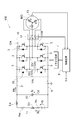
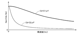
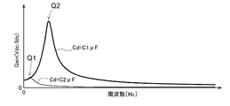
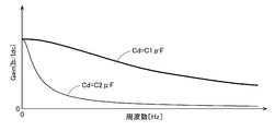
- Block diagram schematically showing an example of a system configuration of a rotating electrical machine drive device Block diagram showing control model of DC power supply Gain (Vdc / Idc) frequency characteristics considering only the resistance component Frequency characteristics of gain (Vdc / Idc) considering resistance and inductive component Frequency characteristics of gain (Ib / Idc) considering only resistance component Frequency characteristics of gain (Ib / Idc) considering resistance and inductive components
- Vdc / Idc frequency characteristics considering only the resistance component Frequency characteristics of gain (Vdc / Idc) considering resistance and inductive component
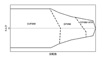
- the figure which shows the condition which determines the switching frequency on the frequency characteristic Diagram showing conditions for determining switching frequency in consideration of operating temperature The figure which shows the correspondence map of the modulation mode according to the torque and rotation speed of a rotary electric machine
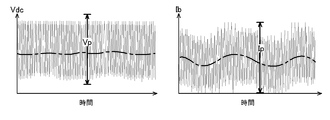
- the figure which shows the correspondence map of the switching frequency according to the power of the rotating electrical machine Waveform diagram showing pulsation of system voltage and battery current Waveform diagram showing pulsation of system voltage and battery
- FIG. 1 schematically shows the configuration of the rotating electrical machine driving device 100.
- the rotating electrical machine MG as a driving force source of the vehicle is a rotating electrical machine that operates by a plurality of phases of alternating current (here, three-phase alternating current), and can function as both an electric motor and a generator.
- a secondary battery such as a nickel metal hydride battery or a lithium ion battery or an electric battery is used as a power source for driving a rotating electric machine.
- a DC power supply such as a multilayer capacitor is installed.
- a battery 11 high-voltage DC power supply
- the direct current flowing through the battery 11 is appropriately referred to as “battery current (power supply current)” in the following description.
- an inverter 10 that performs power conversion between direct current and alternating current is provided between the battery 11 and the rotating electrical machine MG.
- the direct current voltage between the positive electrode power supply line P (high voltage direct current positive electrode line) and the negative electrode power supply line N (high voltage direct current negative electrode line) on the direct current side of the inverter 10 is appropriately referred to as “system voltage Vdc” in the following description.
- the battery 11 can supply electric power to the rotary electric machine MG via the inverter 10 and can store electric power obtained by the electric power generation by the rotary electric machine MG.
- a smoothing capacitor 40 (DC link capacitor) that smoothes the DC voltage (system voltage Vdc) is provided. Smoothing capacitor 40 stabilizes the DC voltage that fluctuates according to fluctuations in power consumption of rotating electrical machine MG.
- the battery 11 includes a plurality of battery cells, and the battery 11 has an internal impedance including an internal resistance (resistance component) and an internal inductance (inductive component). In the present embodiment, these are referred to as battery resistance Rb and battery inductance Lb.
- the battery 11 and the inverter 10 are connected using, for example, a metal wiring member called a bus bar.
- the bus bar also includes a conductor resistance (resistance component) and a conductor inductance (induction component).
- Conductor impedance exists. That is, the wiring connecting the battery 11, the smoothing capacitor 40, and the inverter 10 has wiring impedance including wiring resistance and wiring inductance. In the present embodiment, these are referred to as a wiring resistance Rw and a wiring inductance Lw.
- the internal resistance (power supply internal resistance Rps) of the DC power supply unit including wiring members such as a bus bar when the battery 11 is viewed from the inverter 10 is the sum of the battery resistance Rb and the wiring resistance Rw.
- the internal inductance of the DC power supply unit (power supply internal inductance Lps) is the sum of the battery inductance Lb and the wiring inductance Lw.
- the battery resistance Rb is much larger than the wiring resistance Rw
- the battery inductance Lb is much larger than the wiring inductance Lw.
- the battery resistance Rb is used, and the battery inductance Lb is used as the power source internal inductance Lps.
- the block diagram of FIG. 2 is a control model showing the relationship between the terminal voltage (battery voltage Vb) of the battery 11 serving as the DC power supply unit and the system voltage Vdc.
- the inverter 10 converts DC power having the system voltage Vdc into AC power of a plurality of phases (n is a natural number, n-phase, here 3 phases) and supplies the AC power to the rotating electrical machine MG, and AC power generated by the rotating electrical machine MG. Is converted to DC power and supplied to a DC power source.
- the inverter 10 includes a plurality of switching elements.
- a power semiconductor element such as an IGBT (insulated gate bipolar transistor) or a power MOSFET (metal oxide semiconductor field effector transistor) is preferably used.
- SiC (silicon carbide) devices such as SiC-MOSFET and SiC-SIT (static induction transistor), and GaN-MOSET (Gallium Nitride) can be operated at high frequency. It is also suitable to apply a complex compound power device to the switching element. As shown in FIG. 1, in this embodiment, IGBT3 is used for a switching element as an example.
- the inverter 10 that converts power between a direct current and a plurality of phases of alternating current (here, three-phase alternating current) has a number of arms corresponding to each of the plurality of phases (here, three phases). Consists of a circuit. That is, as shown in FIG. 1, two IGBTs 3 are provided between the DC positive side (positive power supply line P on the positive side of the DC power supply) and the DC negative side (negative power supply line N on the negative side of the DC power supply) of the inverter 10. Are connected in series to form one arm 10A.
- the IGBT 3 connected to the positive power line P is referred to as an upper IGBT (upper switching element or high side switch), and the IGBT 3 connected to the negative power line N is referred to as a lower IGBT (negative switching element or low side switch). ).
- this series circuit When the plural-phase alternating current is a three-phase alternating current, this series circuit (one arm 10A) is connected in parallel with three lines (three phases: 10U, 10V, 10W). That is, a bridge circuit is formed in which a set of series circuits (arms 10A) corresponds to the stator coils corresponding to the U phase, V phase, and W phase of the rotating electrical machine MG.
- the collector terminal of the upper IGBT of each phase is connected to the positive power supply line P, and the emitter terminal is connected to the collector terminal of the lower IGBT of each phase. Further, the emitter terminal of the lower IGBT of each phase is connected to the negative power supply line N.
- a free wheel diode 39 (regenerative diode) is connected to the IGBT 3 in parallel.
- the freewheel diode 39 is connected in parallel to each IGBT 3 in such a manner that the cathode terminal is connected to the collector terminal of the IGBT 3 and the anode terminal is connected to the emitter terminal of the IGBT 3.
- the inverter 10 is controlled by the control device 8.
- the control device 8 includes an ECU (electronic control unit) constructed using a logic circuit such as a microcomputer as a core member.
- the ECU uses a vector control method based on the target torque TM of the rotating electrical machine MG provided to the control device 8 as a request signal from another control device such as a vehicle ECU (not shown). Feedback control is performed to control the rotating electrical machine MG via the inverter 10.
- the current flowing in each stator coil of a plurality of phases is divided into a d-axis that is the direction of the magnetic pole of the rotor and a q-axis that is orthogonal to the d-axis.
- This is a method of performing an operation by converting the coordinates into two vector components.
- the ECU of the control device 8 is configured to have various functional units for current feedback control, and each functional unit is realized by cooperation of hardware such as a microcomputer and software (program). .
- the control device 8 corresponds to the inverter control unit in the present invention.
- the actual current flowing through the stator coil of each phase of the rotating electrical machine MG is detected by the current sensor 12, and the control device 8 acquires the detection result.
- the magnetic pole position at each time point of the rotor of the rotating electrical machine MG is detected by the rotation sensor 13, and the control device 8 acquires the detection result.
- the rotation sensor 13 is configured by, for example, a resolver.
- the magnetic pole position represents the rotation angle of the rotor on the electrical angle.
- the ECU of the control device 8 feedback-controls the rotating electrical machine MG using the detection results of the current sensor 12 and the rotation sensor 13.
- the ECU of the control device 8 controls the rotating electrical machine MG according to a specific modulation mode selected from a plurality of modulation modes.
- the plurality of modulation modes include a three-phase modulation mode (SVPWM) and a two-phase modulation mode (DPWM).
- the three-phase modulation mode is a mode for controlling the rotating electrical machine MG by outputting a PWM pulse signal for three phases based on a comparison between a carrier wave and a signal wave according to an AC voltage command value for each phase.
- the two-phase modulation mode is a mode for controlling the rotating electrical machine MG by outputting a PWM pulse signal for two phases (sequentially switching) and outputting an on / off signal for the remaining one phase (sequentially switching).
- field weakening control may be executed in parallel (DPWM + AFR).
- the field weakening control is a control for decreasing the d-axis current and the q-axis current so that the target torque is output even when the counter electromotive force rises as the rotational speed of the rotating electrical machine MG increases.
- the vehicle is also equipped with a low-voltage battery (low-voltage DC power source) that is a power source having a lower voltage than the battery 11 (not shown).
- the power supply voltage of the low-voltage battery is, for example, 12 to 24 [V], and controls the control device 8 (ECU), the electrical system such as the audio system, the lighting device, the room lighting, the illumination of the instruments, the power window, and the like.
- the control device 8 includes a regulator circuit and the like, and generates a power source suitable for operating a microcomputer and the like by electric power supplied from a low voltage battery.
- the gate terminal which is the control terminal of each IGBT 3 constituting the inverter 10 is connected to the control device 8 (ECU) via the drive circuit 7 and is individually controlled to be switched.
- the operating voltage power supply voltage of the circuit
- the control signal (switching control signal) of the IGBT 3 generated by the control device 8 (ECU) of the low voltage system circuit is supplied to each IGBT 3 as a gate drive signal of the high voltage circuit system via the drive circuit 7.
- the drive circuit 7 is often configured to include an insulating element such as a photocoupler or a transformer.
- the control device 8 is configured with a logic circuit such as a microcomputer as a core.
- the control device 8 is configured with a microcomputer that executes a rotating electrical machine drive program as a core.
- This microcomputer has a CPU core, a program memory, a parameter memory, a work memory, a timer, a port, and the like.
- the CPU core is the core of a microcomputer, and includes an instruction register, an instruction decoder, an ALU (arithmetic logic unit), a flag register, a general-purpose register, an interrupt controller, and the like that perform various operations.
- the form in which the microcomputer is configured by one semiconductor chip is illustrated, but it is of course possible to adopt a form in which the microcomputer unit is configured by combining a plurality of components.
- the program memory is a non-volatile memory in which the rotating electrical machine drive program is stored.
- the parameter memory is a non-volatile memory that stores various parameters that are referred to when the program is executed.
- the parameter memory may be constructed without being distinguished from the program memory.
- the program memory and parameter memory are preferably constituted by a flash memory, for example.
- the work memory is a memory that temporarily stores temporary data during program execution.
- the work memory is composed of DRAM (dynamic RAM) or SRAM (static RAM) that is volatile and can read and write data at high speed.
- the timer measures time using the microcomputer clock cycle as the minimum resolution. For example, the timer monitors the program execution cycle. The timer measures the effective time of the switching control signal that drives the IGBT 3 of the inverter 10 and generates the switching control signal. In addition, the timer manages a control cycle defined in advance by a program or a parameter, such as a cycle (basic control cycle) in which current feedback control is executed once or a switching control signal output cycle (switching cycle Tc). The port outputs a switching control signal of the IGBT 3 of the inverter 10 via a terminal of the microcomputer, and receives a rotation detection signal from the rotation sensor 13 and a current detection signal from the current sensor 12 input to the microcomputer. Terminal control unit.
- the transfer function of the control model of the battery 11 as the DC power supply unit includes, as an impedance component depending on the frequency, the battery inductance Lb and the capacitance of the smoothing capacitor 40 (DC link capacitance Cd). ) And are included. Therefore, the system voltage Vdc is a function of frequency. 3 and 4 show frequency characteristics of a gain (DC side voltage gain) defined by the system voltage Vdc and the system current Idc flowing through the inverter 10.
- the gain (DC side voltage gain) of the system voltage Vdc with respect to the system current Idc is defined by the following equation (1) when the battery inductance Lb is not taken into consideration, and shows a frequency characteristic as shown in FIG. Further, the DC side voltage gain is defined by the following equation (2) when the battery inductance Lb is considered, and shows a frequency characteristic as shown in FIG.
- the DC voltage gain is smaller as the capacitance of the smoothing capacitor 40 (DC link capacitance Cd) is larger.
- the capacity of the smoothing capacitor 40 is reduced in order to reduce the size of the smoothing capacitor 40, the DC side voltage gain increases and the effect of suppressing the pulsation of the system voltage Vdc decreases.
- the resonance between the battery inductance Lb and the DC link capacitance Cd occurs, and this resonance is also taken into consideration. There is a need to.
- the gain of the battery current Ib with respect to the system current Idc is also a function of frequency.
- 5 and 6 show frequency characteristics of a gain (battery current gain) defined by the battery current Ib and the system current Idc flowing through the inverter 10.
- the battery current gain is defined by the following formula (3), and shows a frequency characteristic as shown in FIG.
- the battery current gain is defined by the following equation (4) when the battery inductance Lb is considered, and shows a frequency characteristic as shown in FIG.
- the battery current gain is smaller when the capacitance (DC link capacitance Cd) of the smoothing capacitor 40 is larger.
- the capacity of the smoothing capacitor 40 is reduced in order to reduce the size of the smoothing capacitor 40, the gain increases and the effect of suppressing pulsation generated in the battery current Ib decreases.
- FIG. 5 and FIG. 6 when the battery inductance Lb is considered as the impedance of the DC power supply unit, resonance occurs between the battery inductance Lb and the DC link capacitance Cd, and this resonance is also taken into consideration. There is a need to.
- the battery current gain only increases when the smoothing capacitor 40 is simply reduced in capacity.
- the battery inductance Lb is considered, a frequency at which the battery current gain becomes very large due to resonance appears.
- the gain value at the resonance point (Q2) when the DC link capacitance Cd is C1 [ ⁇ F] is the resonance value (Q1) when the DC link capacitance Cd is 10 times C2 [ ⁇ F]. ) Is very large compared to the gain value.
- the impedance components depending on the frequency are the L component and the C component. Therefore, the values of the DC side voltage gain and battery current gain increase as the frequency increases from zero, reach the maximum value (resonance point) at the resonance frequency, and decrease as the frequency increases with this resonance point as the inflection point.
- the resonance frequency may be calculated based only on the resistance component (R component) and the induction component (L component) of the battery 11.
- the pulsation of the system voltage Vdc and the battery current Ib is generated as the current and voltage fluctuate due to the switching of the IGBT 3 of the inverter 10. That is, the pulsation of the system voltage Vdc and the battery current Ib is generated corresponding to the switching frequency fc of the IGBT 3 (reciprocal of the switching period Tc). For example, it is known that a pulsation having a frequency component “2fc” that is twice the switching frequency fc occurs (ripple frequency). When the resonance frequency ("frp", which will be described later) between the DC link capacitance Cd and the battery inductance Lb is close to the ripple frequency "2fc", the value of the DC voltage gain is large and pulsation increases.
- the resonance frequency frp is determined by the hardware configuration of the rotating electrical machine driving apparatus 100 such as the battery 11. Therefore, it is preferable to appropriately set the switching frequency fc in a range that can be handled by the control device 8 in order to keep the ripple frequency “2fc” away from the resonance frequency frp.
- a method for setting such a switching frequency fc will be described.
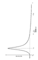
- FIG. 7 shows the simulation result of the DC side voltage gain when the DC link capacitance Cd is C1 [ ⁇ F], the battery inductance Lb is L1 [ ⁇ H], and the battery resistance Rb at room temperature is R2 [ ⁇ ].
- a resonance peak appears at the resonance frequency frp. This resonance frequency frp is obtained by the following equation (5).
- a ripple with a ripple frequency “2fc” that is twice the switching frequency fc of the inverter 10 appears in the system voltage Vdc.
- the ripple frequency “2fc” is close to the resonance frequency frp, the pulsation of the system voltage Vdc increases and the pulsation of the battery current Ib also increases. And durability (life) of the battery 11 is reduced by the pulsation of the battery current Ib.
- the switching frequency fc of the switching control signal is 5 [kHz]
- the ripple frequency “2fc” is 10 [kHz]
- the switching frequency fc when the switching frequency fc is moved away from the resonance frequency frp, the switching frequency fc can be moved to either the low side or the high side. However, if the switching frequency fc is moved to the lower side, the resolution of the switching control of the inverter 10 is reduced, and therefore the smoothness of the rotation control of the rotating electrical machine MG may be reduced. Therefore, it is preferable that the switching frequency fc is adjusted in the direction in which the frequency increases. As one aspect, it is preferable that the switching frequency fc is set so that the frequency of the DC side voltage gain is higher than the frequency at which the value is maximum. As is clear from FIG. 7, the frequency at which the value of the DC voltage gain is maximum is the resonance frequency frp.
- the switching frequency fc When the switching frequency fc is set so as to be higher than the resonance frequency frp, the frequency twice as high as the switching frequency fc is adjusted so as to be higher than the resonance frequency frp. That is, in this case, the lower limit frequency fmin of the switching frequency fc is the resonance frequency frp.
- the frequency (f2) having the same value as the gain when the frequency is “0” is also suitable as the lower limit frequency fmin of the switching frequency fc.
- the value of the DC side voltage gain increases as the frequency increases from zero, reaches the maximum value (resonance point) at the resonance frequency frp, and the frequency increases with this resonance point as an inflection point. As it becomes, it decreases. Accordingly, a frequency higher than the frequency at which the value of the DC side voltage gain becomes a value when the frequency is zero is a frequency higher than the resonance frequency frp. Since the frequency (2fc) twice the switching frequency fc is a higher frequency, it is further away from the resonance frequency frp.
- the resonance frequency frp when the resonance frequency frp is low, the resonance frequency frp and the frequency (2fc) that is twice the switching frequency fc are further separated compared to the case where the switching frequency fc is set in the vicinity of the resonance frequency frp. be able to.
- the gain value when the frequency is “0” is the battery resistance Rb (power supply internal resistance Rps).
- the lower limit frequency fmin is expressed by the following formula (6).
- the battery resistance Rb varies depending on the operating temperature of the battery 11 (the operating temperature of the rotating electrical machine driving device 100). Therefore, the lower limit frequency fmin also varies with temperature.
- FIG. 8 shows the simulation result of the frequency characteristics of the DC side voltage gain at the maximum temperature (for example, 60 [° C.]) and the minimum temperature (for example, ⁇ 40 [° C.]) in the operating temperature range.
- the thick line in FIG. 8 indicates the frequency characteristic at the maximum temperature in the operating temperature range, and the thin line indicates the frequency characteristic at the minimum temperature.
- the battery resistance Rb at the highest temperature is R1 [ ⁇ ]
- the battery resistance Rb at the lowest temperature is R3 [ ⁇ ]
- the switching frequency fc is preferably set based on the frequency characteristic of the DC side voltage gain using the value of the battery resistance Rb (power source internal resistance Rps) at the lowest temperature in the operating temperature range of the rotating electrical machine driving apparatus 100. It is. In this case, the switching frequency fc is set appropriately with the frequency “f3” based on the frequency characteristics at least at the minimum temperature as the lower limit frequency fmin, and does not become an excessively high frequency.
- the switching frequency fc does not prevent the frequency “f1” based on the frequency characteristics at the maximum temperature from being set as the lower limit frequency fmin. Further, as shown in FIG. 7, for example, it does not prevent the frequency “f2” based on the frequency characteristics at normal temperature (eg, 20 to 25 ° C.) from being set as the lower limit frequency fmin.
- the audible range is a frequency band in which human hearing can be sensed, and corresponds to a range of approximately 20 [Hz] to 20 [kHz].
- the switching frequency fc is preferably adjusted so as not to be included in the audible range.
- a frequency equal to or higher than the limit frequency flim (for example, 20 [kHz]) defined in advance to a value higher than the audible range as the lower limit frequency fmin of the switching frequency fc.
- 20 [kHz] which is the upper limit frequency of the audible range
- a higher frequency (for example, 25 [kHz]) is set to a limit frequency flim in consideration of certainty. It is good.
- the lower limit frequency fmin of the switching frequency fc is determined based on the frequency characteristics of the DC side voltage gain and the battery current gain, and the limit frequency flim. It is set according to the size relationship. For example, when the lower limit frequency fmin of the switching frequency fc is set based on the frequency characteristics at normal temperature, when the frequency “f2” is lower than the limit frequency flim (see FIG. 7), the limit frequency flim is set to the lower limit frequency fmin. Is set. For example, when the lower limit frequency fmin of the switching frequency fc is set based on the frequency characteristic at the lowest temperature in the operating temperature range (see FIG.
- the limit frequency flim is similarly set to the lower limit frequency fmin.
- the lower limit frequency fmin of the switching frequency fc is set based on the frequency characteristic at the highest temperature in the operating temperature range, when the frequency “f1” is higher than the limit frequency flim, the frequency “f1” is the lower limit frequency. Set to fmin.
- the system current Idc tends to increase as the power calculated by multiplying the torque of the rotating electrical machine MG and the rotational speed (rotating electrical machine power) increases. Further, as the rotational speed of the rotating electrical machine MG increases, the back electromotive force increases, the modulation factor increases, and the sixth harmonic component of the voltage command value and the harmonic component that is an integral multiple thereof increase. Therefore, even if the gain defined according to the switching frequency fc is the same, the pulsation of the system voltage Vdc and the battery current Ib increases as the torque and the rotational speed of the rotating electrical machine MG increase.
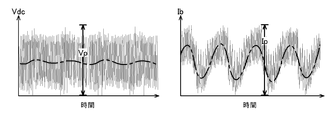
- the pulsation width of the system voltage Vdc is a harmonic component (particularly, a sixth harmonic component and an integral multiple of the harmonic component (6f, 12f, 18f,...; Refer to the thick one-dot chain line in FIG. 11 and the like) is the difference between the maximum value and the minimum value in the superimposed voltage waveform. If the pulsation width of the system voltage Vdc becomes large and does not fall within the range of a predetermined voltage ripple allowable width Vp (for example, 40 [V]; see FIG. 11 etc.), sufficient protection of the IGBT 3 (switching element) is achieved. Cannot be planned.
- the pulsation width of the battery current Ib is a harmonic component (particularly a sixth harmonic component and an integral multiple of the harmonic component (6f) generated in the basic ripple due to the ripple frequency 2fc in accordance with the rotation speed of the rotating electrical machine MG. , 12f, 18f,...; See the thick one-dot chain line in FIG. 11 etc.) is the difference between the maximum value and the minimum value in the current waveform superimposed. If the pulsation width of the battery current Ib increases and does not fall within the range of the current ripple allowable width Ip (for example, 60 [A]; see FIG. 11 and the like), the battery 11 cannot be sufficiently protected. .
- the pulsation width of the system voltage Vdc and the battery current Ib which relatively increases as the power of the rotating electrical machine MG increases, shortens the switching period Tc (in other words, increases the switching frequency fc).
- the gain is reduced by increasing the switching frequency fc in the frequency range higher than the resonance frequency frp, and therefore the pulsation width of the system voltage Vdc and the like even when the system current Idc is increased. Can be kept small. Therefore, it is preferable to set the switching frequency fc to a different value according to both the torque defining the power of the rotating electrical machine MG and the rotational speed. As one aspect, it is preferable to set the switching frequency fc higher as the power of the rotating electrical machine MG increases.
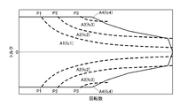
- FIG. 10 shows an operation map of the rotating electrical machine MG.
- a plurality of operation regions A1 to A4 are set according to the torque and the rotational speed of the rotating electrical machine MG.
- the plurality of operation areas A1 to A4 are areas according to the power calculated by multiplying the torque of the rotating electrical machine MG and the rotation speed.
- the operation area A1 is an area in which the power of the rotating electrical machine MG is less than a first reference value P1 defined in advance on an absolute value basis.
- the operation area A2 is an area based on an absolute value, in which the power of the rotating electrical machine MG is equal to or greater than the first reference value P1 and less than the second reference value P2 that is defined in advance as a value greater than the first reference value P1.
- the operation area A3 is an area based on an absolute value, in which the power of the rotating electrical machine MG is greater than or equal to the second reference value P2 and less than the third reference value P3 that is defined in advance as a value greater than the second reference value P2.
- the operation area A4 is an area in which the power of the rotating electrical machine MG is greater than or equal to the third reference value P3 on an absolute value basis.
- the switching frequency fc is set to a different value for each of the plurality of operation regions A1 to A4.
- the frequency fc1 is set in the operation region A1
- the frequency fc2 (> fc1) is set in the operation region A2
- the frequency fc3 (> fc2) is set in the operation region A3
- the frequency fc4 (>) is set in the operation region A4.
- fc3) is set. That is, in this example, a switching frequency fc that is a constant value is set for each of the plurality of operation regions A1 to A4, and the switching frequency fc is set to change stepwise between adjacent operation regions.
- the switching frequency fc higher stepwise as the power of the rotating electrical machine MG increases.
- the frequency fc1 corresponding to the operation region A1 is set to be equal to or higher than the lower limit frequency fmin of the switching frequency fc set based on the above-described DC side voltage gain, battery current gain, and limit frequency flim.
- the frequency fc1 is set to be equal to or lower than an upper limit frequency fmax of a switching frequency fc described later. The same applies to the frequencies fc2 to fc4.
- FIG. 11 to 13 show waveforms of the system voltage Vdc and the battery current Ib, which are simulated by changing the switching frequency fc according to the power of the rotating electrical machine MG.
- FIG. 11 shows a case where the switching frequency is 20 [kHz] with respect to the rotational speed of 1000 [rpm]
- FIG. 12 shows that the switching frequency is 30 [rpm] with respect to the rotational speed of 2000 [rpm].
- FIG. 13 shows a case where the switching frequency is 40 [kHz] with respect to the rotational speed of 3000 [rpm].
- the pulsation widths of the system voltage Vdc and the battery current Ib are set to the allowable widths Vp and Ip respectively defined. It is within the range.
- the upper limit frequency fmax of the switching frequency fc is also defined.
- the switching frequency fc is increased, the number of times of switching per unit time is increased, so that the switching loss in the inverter 10 is also increased. Therefore, it is preferable that conditions are defined not only for the lower limit frequency fmin but also for the upper limit frequency fmax.
- the frequency at which the switching loss of the inverter 10 is equal to or lower than a predetermined upper limit loss be the upper limit frequency fmax of the switching frequency fc.
- the supply source of the battery 11, the supply source of the IGBT 3 of the inverter 10, and the supply source of the control device 8 may be different. That is, it is desirable that the control device 8 can set an appropriate switching frequency fc even when the battery resistance Rb, the battery inductance Lb, the withstand voltage of the IGBT 3 and the like differ depending on the vehicle. As described above, according to the present invention, the switching frequency fc can be set according to the torque and the rotational speed of the rotating electrical machine MG, and the technique can be widely applied.
- the switching frequency fc is conceptually set so as to satisfy the following criteria. That is, the switching frequency fc is (A) The pulsation of the system voltage Vdc generated according to the switching frequency fc is within a range in which the IGBT 3 (switching element) of the inverter 10 can be protected. (B) The pulsation of the battery current Ib generated according to the switching frequency fc is within a range in which the battery 11 can be protected. (C) There is no audible noise, (D) the switching loss of the inverter 10 corresponding to the switching frequency fc is not excessively large; It is preferable to set so as to satisfy all of the above.
- the lower limit frequency fmin of the switching frequency fc is (A ′)
- the pulsation width of the system voltage Vdc generated according to the switching frequency fc is within the range of the allowable width (voltage ripple allowable width Vp) defined in advance based on the breakdown voltage of the IGBT 3 (switching element) of the inverter 10.
- the pulsation width of the battery current Ib generated according to the switching frequency fc is within a range of an allowable width (current ripple allowable width Ip) defined in advance so that deterioration of the battery 11 can be suppressed.
- C ′ being equal to or higher than a limit frequency flim defined in advance to a value above the audible range; It is preferable to set so as to satisfy all of the above.
- the upper limit frequency fmax of the switching frequency fc is (D ′) the switching loss of the inverter 10 corresponding to the switching frequency fc is less than or equal to a predetermined upper limit loss; Is preferably set so as to satisfy the above.
- the switching frequency fc set in this way starts from a predetermined frequency equal to or higher than the limit frequency flim, and increases stepwise as the power of the rotating electrical machine MG increases.
- the rotation synchronization control mode is a control mode that outputs a predetermined number of pulses in synchronization with the rotation of the rotating electrical machine MG (for example, a 1-pulse control mode or a 5-pulse control mode).
- DPWM normal two-phase modulation mode
- the two-phase modulation mode with field weakening control (not in the pulse modulation mode) DPWM + AFR) is set.
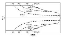
- the switching frequency fc may be variably set according to the modulation factor M instead of the power of the rotating electrical machine MG described above (see FIG. 14). That is, even if the switching frequency fc starts from a predetermined frequency equal to or higher than the limit frequency flim and is set to increase stepwise as the modulation factor M increases (fc1 ′ ⁇ fc2 ′ ⁇ fc3 ′ ⁇ fc4 ′). Good.
- the modulation factor M is an index representing the ratio of the effective value of the AC voltage command value to the system voltage Vdc, and is expressed by the following equation (7) using the biaxial voltage command values Vd and Vq in the vector control method. Calculated.
- the operation regions B1 to B4 corresponding to the modulation factor M are set to the torque of the rotating electrical machine MG and It is also possible to map in correspondence with the rotation speed. Even when the switching frequency fc is set in accordance with the modulation factor M, it is preferable to satisfy the above conditions (a ′) to (d ′).
- the switching frequency fc when the switching frequency fc is variably set according to the power of the rotating electrical machine MG or the modulation factor M, it may be changed continuously instead of stepwise. That is, the switching frequency fc may be set to start from a predetermined frequency equal to or higher than the limit frequency flim and continuously increase as the power of the rotating electrical machine MG or the modulation factor M increases.
- control device 8 sets switching frequency fc to a different value according to both the torque and rotational speed of rotating electrical machine MG, according to the pulsation width of system voltage Vdc and the pulsation width of battery current Ib. More specifically, the control device 8 sets the switching frequency fc so that the pulsation width of the system voltage Vdc and the pulsation width of the battery current Ib are within a predetermined allowable range. Set different values depending on both rotation speeds. In this case, noise in the audible range may occur, but at least the IGBT 3 (switching element) of the inverter 10 and the battery 11 can be protected.
- the control device 8 sets the switching frequency fc to a different value according to both the torque and the rotational speed of the rotating electrical machine MG according to the pulsation width of the system voltage Vdc. Set. More specifically, the control device 8 sets the switching frequency fc to a value that varies depending on both the torque and the rotational speed of the rotating electrical machine MG so that the pulsation width of the system voltage Vdc falls within a predetermined allowable range. Set to. In this case, at least the IGBT 3 (switching element) of the inverter 10 can be protected.
- the control device 8 sets the switching frequency fc to a different value according to both the torque and the rotational speed of the rotating electrical machine MG according to the pulsation width of the battery current Ib. Set. More specifically, the control device 8 sets the switching frequency fc to a value that varies depending on both the torque and the rotation speed of the rotating electrical machine MG so that the pulsation width of the battery current Ib is within a predetermined allowable range. Set to. In this case, at least the battery 11 can be protected.
- the configuration of the present invention is also very suitable when the SiC device such as SiC-MOSFET or SiC-SIT is used as the switching element. ing.
- these SiC devices have less switching loss than Si devices and can operate stably even at high temperatures, so that even with a relatively high switching frequency, the loss can be suppressed and what can be done stably. It has characteristics. Therefore, the configuration of the present invention is particularly suitable when such a SiC device is used as a switching element and a wide frequency range is used as a switching frequency.
- the present invention can be used for a rotating electrical machine drive device that drives and controls an AC rotating electrical machine.
Landscapes
- Engineering & Computer Science (AREA)
- Power Engineering (AREA)
- Transportation (AREA)
- Mechanical Engineering (AREA)
- Life Sciences & Earth Sciences (AREA)
- Sustainable Development (AREA)
- Sustainable Energy (AREA)
- Control Of Ac Motors In General (AREA)
- Inverter Devices (AREA)
- Electric Propulsion And Braking For Vehicles (AREA)
Abstract
Description
直流電源と前記回転電機との間に電気的に介在されて、直流と交流との間で電力を変換するインバータと、
前記直流電源と前記インバータとの間に電気的に介在され、前記インバータの直流側の正極と負極との間に接続される平滑コンデンサと、
前記インバータのスイッチング素子を、予め規定されたスイッチング周波数に従ってスイッチング制御するインバータ制御部と、を備え、
前記インバータ制御部は、前記インバータの直流側の電圧であるシステム電圧の脈動幅と前記直流電源を流れる電流である電源電流の脈動幅とに応じ、前記スイッチング周波数を、前記回転電機のトルク及び回転数の双方に応じて異なる値に設定する点にある。
直流電源と前記回転電機との間に電気的に介在されて、直流と交流との間で電力を変換するインバータと、
前記直流電源と前記インバータとの間に電気的に介在され、前記インバータの直流側の正極と負極との間に接続される平滑コンデンサと、
前記インバータのスイッチング素子を、予め規定されたスイッチング周波数に従ってスイッチング制御するインバータ制御部と、を備え、
前記インバータ制御部は、前記インバータの直流側の電圧であるシステム電圧の脈動幅が予め規定された許容幅の範囲内に収まるように、前記スイッチング周波数を、前記回転電機のトルク及び回転数の双方に応じて異なる値に設定する点にある。
直流電源と前記回転電機との間に電気的に介在されて、直流と交流との間で電力を変換するインバータと、
前記直流電源と前記インバータとの間に電気的に介在され、前記インバータの直流側の正極と負極との間に接続される平滑コンデンサと、
前記インバータのスイッチング素子を、予め規定されたスイッチング周波数に従ってスイッチング制御するインバータ制御部と、を備え、
前記インバータ制御部は、前記直流電源を流れる電流である電源電流の脈動幅が予め規定された許容幅の範囲内に収まるように、前記スイッチング周波数を、前記回転電機のトルク及び回転数の双方に応じて異なる値に設定する点にある。






(a)スイッチング周波数fcに応じて生じるシステム電圧Vdcの脈動が、インバータ10のIGBT3(スイッチング素子)の保護を図ることができるような範囲に収まること、
(b)スイッチング周波数fcに応じて生じるバッテリ電流Ibの脈動が、バッテリ11の保護を図ることができるような範囲に収まること、
(c)可聴域の騒音が出ないこと、
(d)スイッチング周波数fcに応じたインバータ10のスイッチング損失が大きくなり過ぎないこと、
の全てを満足するように設定されると好適である。
(a’)スイッチング周波数fcに応じて生じるシステム電圧Vdcの脈動幅が、インバータ10のIGBT3(スイッチング素子)の耐圧に基づいて予め規定される許容幅(電圧リップル許容幅Vp)の範囲内に収まること、
(b’)スイッチング周波数fcに応じて生じるバッテリ電流Ibの脈動幅が、バッテリ11の劣化を抑制できるように予め規定される許容幅(電流リップル許容幅Ip)の範囲内に収まること、
(c’)可聴域以上の値に予め規定された制限周波数flim以上であること、
の全てを満足するように設定されると好適である。
(d’)スイッチング周波数fcに応じたインバータ10のスイッチング損失が予め規定された上限損失以下に収まること、
を満足するように設定されると好適である。

10 :インバータ
11 :バッテリ(直流電源)
40 :平滑コンデンサ
100 :回転電機駆動装置
A :動作領域
B :動作領域
Ib :バッテリ電流(電源電流)
Idc :システム電流
Ip :電流リップル許容幅
M :変調率
MG :回転電機
Vdc :システム電圧
Vp :電圧リップル許容幅
fc :スイッチング周波数
flim :制限周波数
Claims (10)
- 交流の回転電機を駆動制御する回転電機駆動装置であって、
直流電源と前記回転電機との間に電気的に介在されて、直流と交流との間で電力を変換するインバータと、
前記直流電源と前記インバータとの間に電気的に介在され、前記インバータの直流側の正極と負極との間に接続される平滑コンデンサと、
前記インバータのスイッチング素子を、予め規定されたスイッチング周波数に従ってスイッチング制御するインバータ制御部と、を備え、
前記インバータ制御部は、前記インバータの直流側の電圧であるシステム電圧の脈動幅と前記直流電源を流れる電流である電源電流の脈動幅とに応じ、前記スイッチング周波数を、前記回転電機のトルク及び回転数の双方に応じて異なる値に設定する回転電機駆動装置。 - 前記インバータ制御部は、前記インバータの直流側の電圧であるシステム電圧の脈動幅と前記直流電源を流れる電流である電源電流の脈動幅とがそれぞれ予め規定された許容幅の範囲内に収まるように、前記スイッチング周波数を、前記回転電機のトルク及び回転数の双方に応じて異なる値に設定する請求項1に記載の回転電機駆動装置。
- 交流の回転電機を駆動制御する回転電機駆動装置であって、
直流電源と前記回転電機との間に電気的に介在されて、直流と交流との間で電力を変換するインバータと、
前記直流電源と前記インバータとの間に電気的に介在され、前記インバータの直流側の正極と負極との間に接続される平滑コンデンサと、
前記インバータのスイッチング素子を、予め規定されたスイッチング周波数に従ってスイッチング制御するインバータ制御部と、を備え、
前記インバータ制御部は、前記インバータの直流側の電圧であるシステム電圧の脈動幅に応じ、前記スイッチング周波数を、前記回転電機のトルク及び回転数の双方に応じて異なる値に設定する回転電機駆動装置。 - 前記インバータ制御部は、前記インバータの直流側の電圧であるシステム電圧の脈動幅が予め規定された許容幅の範囲内に収まるように、前記スイッチング周波数を、前記回転電機のトルク及び回転数の双方に応じて異なる値に設定する請求項3に記載の回転電機駆動装置。
- 交流の回転電機を駆動制御する回転電機駆動装置であって、
直流電源と前記回転電機との間に電気的に介在されて、直流と交流との間で電力を変換するインバータと、
前記直流電源と前記インバータとの間に電気的に介在され、前記インバータの直流側の正極と負極との間に接続される平滑コンデンサと、
前記インバータのスイッチング素子を、予め規定されたスイッチング周波数に従ってスイッチング制御するインバータ制御部と、を備え、
前記インバータ制御部は、前記直流電源を流れる電流である電源電流の脈動幅に応じ、前記スイッチング周波数を、前記回転電機のトルク及び回転数の双方に応じて異なる値に設定する回転電機駆動装置。 - 前記インバータ制御部は、前記直流電源を流れる電流である電源電流の脈動幅が予め規定された許容幅の範囲内に収まるように、前記スイッチング周波数を、前記回転電機のトルク及び回転数の双方に応じて異なる値に設定する請求項5に記載の回転電機駆動装置。
- 前記インバータ制御部は、前記回転電機のトルクと回転数とを乗じて算出される回転電機パワー、又は前記インバータの直流側の電圧であるシステム電圧に対する交流電圧指令値の実効値の比率を表す変調率が大きくなるに従って、前記スイッチング周波数を高く設定する請求項1から6のいずれか一項に記載の回転電機駆動装置。
- 前記インバータ制御部は、可聴域以上の値に予め規定された制限周波数以上の周波数となるように、かつ、前記インバータの直流側の電圧であるシステム電圧を前記インバータの直流側の電流であるシステム電流で除した直流側電圧ゲインの周波数特性において、前記直流側電圧ゲインの値が最大となる周波数よりも高い周波数となるように、前記スイッチング周波数を設定する請求項1から7のいずれか一項に記載の回転電機駆動装置。
- 前記インバータ制御部は、前記制限周波数以上の周波数となるように、かつ、前記直流側電圧ゲインの周波数特性において、前記直流側電圧ゲインの値が周波数をゼロとしたときの値と同じとなる周波数以上の周波数となるように、前記スイッチング周波数を設定する請求項8に記載の回転電機駆動装置。
- 前記回転電機のトルクと回転数とを乗じて算出されるパワーに応じて複数の動作領域が設定され、
前記インバータ制御部は、前記スイッチング周波数を前記動作領域毎に異なる値に設定する請求項1から9のいずれか一項に記載の回転電機駆動装置。
Priority Applications (4)
| Application Number | Priority Date | Filing Date | Title |
|---|---|---|---|
| DE112014000414.6T DE112014000414T5 (de) | 2013-03-29 | 2014-03-28 | Antriebseinrichtung für eine elektrische Drehmaschine |
| JP2015508767A JP6056960B2 (ja) | 2013-03-29 | 2014-03-28 | 回転電機駆動装置 |
| CN201480011006.7A CN105027424B (zh) | 2013-03-29 | 2014-03-28 | 旋转电机驱动装置 |
| US14/761,802 US9543885B2 (en) | 2013-03-29 | 2014-03-28 | Rotary electric machine driving device |
Applications Claiming Priority (2)
| Application Number | Priority Date | Filing Date | Title |
|---|---|---|---|
| JP2013073345 | 2013-03-29 | ||
| JP2013-073345 | 2013-03-29 |
Publications (1)
| Publication Number | Publication Date |
|---|---|
| WO2014157629A1 true WO2014157629A1 (ja) | 2014-10-02 |
Family
ID=51624585
Family Applications (1)
| Application Number | Title | Priority Date | Filing Date |
|---|---|---|---|
| PCT/JP2014/059145 Ceased WO2014157629A1 (ja) | 2013-03-29 | 2014-03-28 | 回転電機駆動装置 |
Country Status (5)
| Country | Link |
|---|---|
| US (1) | US9543885B2 (ja) |
| JP (1) | JP6056960B2 (ja) |
| CN (1) | CN105027424B (ja) |
| DE (1) | DE112014000414T5 (ja) |
| WO (1) | WO2014157629A1 (ja) |
Cited By (4)
| Publication number | Priority date | Publication date | Assignee | Title |
|---|---|---|---|---|
| JP2017192197A (ja) * | 2016-04-12 | 2017-10-19 | 株式会社デンソー | 交流電動機の制御装置 |
| JP2020156223A (ja) * | 2019-03-20 | 2020-09-24 | トヨタ自動車株式会社 | 駆動装置 |
| WO2021079841A1 (ja) * | 2019-10-24 | 2021-04-29 | 三菱重工サーマルシステムズ株式会社 | 制御装置、電動圧縮機、制御方法、プログラム |
| KR20220041106A (ko) * | 2019-07-29 | 2022-03-31 | 발레오 지멘스 이오토모티브 독일 게엠베하 | 제어 장치, 인버터, 인버터 및 전기 머신을 구비하는 어셈블리, 인버터를 작동시키는 방법 및 컴퓨터 프로그램 |
Families Citing this family (12)
| Publication number | Priority date | Publication date | Assignee | Title |
|---|---|---|---|---|
| JP6279151B2 (ja) * | 2015-04-27 | 2018-02-14 | 三菱電機株式会社 | 交流回転機の制御装置および電動パワーステアリング装置 |
| JP6424772B2 (ja) * | 2015-08-07 | 2018-11-21 | 株式会社デンソー | 交流回転電機の制御装置 |
| US11251622B1 (en) * | 2016-03-18 | 2022-02-15 | Apple Inc. | Converter employing differing switch types in parallel |
| AU2018392788B2 (en) * | 2017-12-23 | 2022-09-22 | Enphase Energy, Inc. | Three-phase AC/AC converter with quasi-sine wave HF series resonant link |
| EP3762191B1 (en) | 2018-03-09 | 2024-09-04 | ABB Schweiz AG | Time-spread control cycles for robotic servomotors |
| US11482920B2 (en) | 2018-11-13 | 2022-10-25 | Carrier Corporation | Single stage, two level pulse width modulation strategies for active harmonic filters |
| DE102019200992A1 (de) * | 2019-01-28 | 2020-07-30 | Robert Bosch Gmbh | Verfahren zur Steuerung eines Inverters |
| DE102019120439A1 (de) * | 2019-07-29 | 2021-02-04 | Valeo Siemens Eautomotive Germany Gmbh | Steuereinrichtung, Wechselrichter, Anordnung mit einem Wechselrichter und einer elektrischen Maschine, Verfahren zum Betreiben eines Wechselrichters sowie Computerprogramm |
| DE102020109329B4 (de) | 2020-04-03 | 2022-01-13 | Dr. Ing. H.C. F. Porsche Aktiengesellschaft | Elektrisches Antriebssystem mit magnetokalorischer Temperiereinrichtung für Stromschienen eines Elektro- oder Hybridfahrzeugs |
| JP7468435B2 (ja) | 2021-03-30 | 2024-04-16 | 株式会社デンソー | 電力変換装置の制御装置 |
| CN113708702B (zh) * | 2021-09-01 | 2023-08-22 | 臻驱科技(上海)有限公司 | 一种电机控制器的降频控制方法及系统 |
| US20250007388A1 (en) * | 2021-11-25 | 2025-01-02 | Mitsubishi Electric Corporation | Power converter, motor driver, and refrigeration cycle applied equipment |
Citations (3)
| Publication number | Priority date | Publication date | Assignee | Title |
|---|---|---|---|---|
| WO2009001738A1 (ja) * | 2007-06-26 | 2008-12-31 | Toyota Jidosha Kabushiki Kaisha | モータ駆動システムおよびその制御方法 |
| WO2011155013A1 (ja) * | 2010-06-07 | 2011-12-15 | トヨタ自動車株式会社 | 電力制御器の制御装置および制御方法 |
| JP2013027149A (ja) * | 2011-07-21 | 2013-02-04 | Panasonic Corp | モータ駆動用インバータ制御回路およびそれを用いた電気掃除機 |
Family Cites Families (4)
| Publication number | Priority date | Publication date | Assignee | Title |
|---|---|---|---|---|
| JP4301913B2 (ja) * | 2003-09-29 | 2009-07-22 | オークマ株式会社 | モータ制御装置 |
| US7680234B2 (en) * | 2004-02-24 | 2010-03-16 | Schneider Electric USA, Inc. | Method and apparatus for signal phase locking |
| JP2009106046A (ja) | 2007-10-23 | 2009-05-14 | Hitachi Ltd | 自動車用電力変換装置 |
| WO2010049976A1 (ja) * | 2008-10-31 | 2010-05-06 | 三菱電機株式会社 | 電力変換装置 |
-
2014
- 2014-03-28 JP JP2015508767A patent/JP6056960B2/ja active Active
- 2014-03-28 DE DE112014000414.6T patent/DE112014000414T5/de active Pending
- 2014-03-28 WO PCT/JP2014/059145 patent/WO2014157629A1/ja not_active Ceased
- 2014-03-28 CN CN201480011006.7A patent/CN105027424B/zh active Active
- 2014-03-28 US US14/761,802 patent/US9543885B2/en active Active
Patent Citations (3)
| Publication number | Priority date | Publication date | Assignee | Title |
|---|---|---|---|---|
| WO2009001738A1 (ja) * | 2007-06-26 | 2008-12-31 | Toyota Jidosha Kabushiki Kaisha | モータ駆動システムおよびその制御方法 |
| WO2011155013A1 (ja) * | 2010-06-07 | 2011-12-15 | トヨタ自動車株式会社 | 電力制御器の制御装置および制御方法 |
| JP2013027149A (ja) * | 2011-07-21 | 2013-02-04 | Panasonic Corp | モータ駆動用インバータ制御回路およびそれを用いた電気掃除機 |
Cited By (10)
| Publication number | Priority date | Publication date | Assignee | Title |
|---|---|---|---|---|
| JP2017192197A (ja) * | 2016-04-12 | 2017-10-19 | 株式会社デンソー | 交流電動機の制御装置 |
| JP2020156223A (ja) * | 2019-03-20 | 2020-09-24 | トヨタ自動車株式会社 | 駆動装置 |
| CN111740680A (zh) * | 2019-03-20 | 2020-10-02 | 丰田自动车株式会社 | 驱动装置 |
| JP7115378B2 (ja) | 2019-03-20 | 2022-08-09 | トヨタ自動車株式会社 | 駆動装置 |
| CN111740680B (zh) * | 2019-03-20 | 2023-11-07 | 丰田自动车株式会社 | 驱动装置 |
| KR20220041106A (ko) * | 2019-07-29 | 2022-03-31 | 발레오 지멘스 이오토모티브 독일 게엠베하 | 제어 장치, 인버터, 인버터 및 전기 머신을 구비하는 어셈블리, 인버터를 작동시키는 방법 및 컴퓨터 프로그램 |
| JP2022542991A (ja) * | 2019-07-29 | 2022-10-07 | ヴァレオ、シーメンス、イーオートモーティブ、ジャーマニー、ゲーエムベーハー | 制御装置、インバータ、インバータおよび電気機械を有するアセンブリ、ならびにインバータを動作させる方法およびコンピュータプログラム |
| KR102848444B1 (ko) | 2019-07-29 | 2025-08-20 | 발레오 지멘스 이오토모티브 독일 게엠베하 | 제어 장치, 인버터, 인버터 및 전기 머신을 구비하는 어셈블리, 인버터를 작동시키는 방법 및 컴퓨터 프로그램 |
| WO2021079841A1 (ja) * | 2019-10-24 | 2021-04-29 | 三菱重工サーマルシステムズ株式会社 | 制御装置、電動圧縮機、制御方法、プログラム |
| US12326145B2 (en) | 2019-10-24 | 2025-06-10 | Mitsubishi Heavy Industries Thermal Systems, Ltd. | Control device, electric compressor, control method, and program |
Also Published As
| Publication number | Publication date |
|---|---|
| DE112014000414T5 (de) | 2015-10-08 |
| CN105027424A (zh) | 2015-11-04 |
| JPWO2014157629A1 (ja) | 2017-02-16 |
| JP6056960B2 (ja) | 2017-01-11 |
| CN105027424B (zh) | 2017-09-12 |
| US9543885B2 (en) | 2017-01-10 |
| US20150365040A1 (en) | 2015-12-17 |
Similar Documents
| Publication | Publication Date | Title |
|---|---|---|
| JP6056960B2 (ja) | 回転電機駆動装置 | |
| JP6004086B2 (ja) | 回転電機駆動装置 | |
| CN102177650B (zh) | 电动机驱动器和控制它的方法 | |
| JP4462243B2 (ja) | 負荷駆動装置およびそれを備える車両 | |
| JP4623065B2 (ja) | 電圧変換装置および電圧変換方法 | |
| JP7135604B2 (ja) | 回転電機制御装置 | |
| US10027271B2 (en) | Rotating electrical machine control device | |
| JP6218906B1 (ja) | 電力変換装置 | |
| JP6802126B2 (ja) | インバータ制御装置 | |
| CN106458001A (zh) | 车辆用驱动装置 | |
| CN103843239A (zh) | 电压变换装置的控制装置以及控制方法 | |
| JP6004087B2 (ja) | 回転電機駆動装置 | |
| US12348040B2 (en) | Power storage system | |
| JP6423323B2 (ja) | 電力変換装置 | |
| US11223296B2 (en) | Power conversion device | |
| JP5708283B2 (ja) | 車両 | |
| JP2010220306A (ja) | モータの制御装置 | |
| US9712100B2 (en) | Electric rotating machine and control method therefor | |
| WO2018179662A1 (ja) | 電力変換装置および電力変換方法 |
Legal Events
| Date | Code | Title | Description |
|---|---|---|---|
| WWE | Wipo information: entry into national phase |
Ref document number: 201480011006.7 Country of ref document: CN |
|
| 121 | Ep: the epo has been informed by wipo that ep was designated in this application |
Ref document number: 14773784 Country of ref document: EP Kind code of ref document: A1 |
|
| WWE | Wipo information: entry into national phase |
Ref document number: 14761802 Country of ref document: US |
|
| WWE | Wipo information: entry into national phase |
Ref document number: 1120140004146 Country of ref document: DE Ref document number: 112014000414 Country of ref document: DE |
|
| ENP | Entry into the national phase |
Ref document number: 2015508767 Country of ref document: JP Kind code of ref document: A |
|
| 122 | Ep: pct application non-entry in european phase |
Ref document number: 14773784 Country of ref document: EP Kind code of ref document: A1 |