WO2014157461A1 - 照明装置及び表示装置 - Google Patents
照明装置及び表示装置 Download PDFInfo
- Publication number
- WO2014157461A1 WO2014157461A1 PCT/JP2014/058753 JP2014058753W WO2014157461A1 WO 2014157461 A1 WO2014157461 A1 WO 2014157461A1 JP 2014058753 W JP2014058753 W JP 2014058753W WO 2014157461 A1 WO2014157461 A1 WO 2014157461A1
- Authority
- WO
- WIPO (PCT)
- Prior art keywords
- light
- unit
- prism
- guide plate
- light guide
- Prior art date
- Legal status (The legal status is an assumption and is not a legal conclusion. Google has not performed a legal analysis and makes no representation as to the accuracy of the status listed.)
- Ceased
Links
Images







Classifications
-
- G—PHYSICS
- G02—OPTICS
- G02B—OPTICAL ELEMENTS, SYSTEMS OR APPARATUS
- G02B6/00—Light guides; Structural details of arrangements comprising light guides and other optical elements, e.g. couplings
- G02B6/0001—Light guides; Structural details of arrangements comprising light guides and other optical elements, e.g. couplings specially adapted for lighting devices or systems
- G02B6/0011—Light guides; Structural details of arrangements comprising light guides and other optical elements, e.g. couplings specially adapted for lighting devices or systems the light guides being planar or of plate-like form
- G02B6/0033—Means for improving the coupling-out of light from the light guide
- G02B6/005—Means for improving the coupling-out of light from the light guide provided by one optical element, or plurality thereof, placed on the light output side of the light guide
- G02B6/0053—Prismatic sheet or layer; Brightness enhancement element, sheet or layer
-
- G—PHYSICS
- G02—OPTICS
- G02B—OPTICAL ELEMENTS, SYSTEMS OR APPARATUS
- G02B6/00—Light guides; Structural details of arrangements comprising light guides and other optical elements, e.g. couplings
- G02B6/0001—Light guides; Structural details of arrangements comprising light guides and other optical elements, e.g. couplings specially adapted for lighting devices or systems
- G02B6/0011—Light guides; Structural details of arrangements comprising light guides and other optical elements, e.g. couplings specially adapted for lighting devices or systems the light guides being planar or of plate-like form
- G02B6/0033—Means for improving the coupling-out of light from the light guide
- G02B6/0035—Means for improving the coupling-out of light from the light guide provided on the surface of the light guide or in the bulk of it
- G02B6/0038—Linear indentations or grooves, e.g. arc-shaped grooves or meandering grooves, extending over the full length or width of the light guide
-
- G—PHYSICS
- G02—OPTICS
- G02B—OPTICAL ELEMENTS, SYSTEMS OR APPARATUS
- G02B6/00—Light guides; Structural details of arrangements comprising light guides and other optical elements, e.g. couplings
- G02B6/0001—Light guides; Structural details of arrangements comprising light guides and other optical elements, e.g. couplings specially adapted for lighting devices or systems
- G02B6/0011—Light guides; Structural details of arrangements comprising light guides and other optical elements, e.g. couplings specially adapted for lighting devices or systems the light guides being planar or of plate-like form
- G02B6/0033—Means for improving the coupling-out of light from the light guide
- G02B6/005—Means for improving the coupling-out of light from the light guide provided by one optical element, or plurality thereof, placed on the light output side of the light guide
- G02B6/0055—Reflecting element, sheet or layer
-
- G—PHYSICS
- G02—OPTICS
- G02B—OPTICAL ELEMENTS, SYSTEMS OR APPARATUS
- G02B6/00—Light guides; Structural details of arrangements comprising light guides and other optical elements, e.g. couplings
- G02B6/0001—Light guides; Structural details of arrangements comprising light guides and other optical elements, e.g. couplings specially adapted for lighting devices or systems
- G02B6/0011—Light guides; Structural details of arrangements comprising light guides and other optical elements, e.g. couplings specially adapted for lighting devices or systems the light guides being planar or of plate-like form
- G02B6/0081—Mechanical or electrical aspects of the light guide and light source in the lighting device peculiar to the adaptation to planar light guides, e.g. concerning packaging
- G02B6/0086—Positioning aspects
- G02B6/0091—Positioning aspects of the light source relative to the light guide
Definitions
- the present invention relates to a lighting device and a display device.
- the display elements of image display devices such as television receivers are shifting from conventional cathode ray tubes to thin display panels such as liquid crystal panels and plasma display panels, which enables thinning of image display devices.
- a backlight device is separately required as a lighting device, and the backlight device is roughly classified into a direct type and an edge light type according to the mechanism.
- the edge-light type backlight device guides the light from the light source placed at the end, and supplies the light from the light guide plate to the liquid crystal panel as a uniform planar light by applying an optical action to the light.
- an optical member described in Patent Document 1 below is known.
- This Patent Document 1 has a configuration in which a plurality of cylindrical lenses are arranged in parallel on the light exit surface of the light guide plate so that the light guide plate has a condensing function and a prism sheet is disposed on the light exit surface side. It is disclosed.
- Patent Document 1 (Problems to be solved by the invention)
- the condensing action is enhanced by matching the condensing directions of the cylindrical lens provided on the light exit surface of the light guide plate and the prism sheet disposed on the light exit surface.
- the light condensing action is insufficient in the above configuration, and there is still room for improvement.
- the present invention has been completed based on the above-described circumstances, and an object thereof is to improve luminance.
- the illuminating device of the present invention has a light source and a square plate shape, and at least one of a pair of end faces that form opposite sides among the outer peripheral end faces is a light incident surface facing the light source, and one plate
- a light guide plate whose surface is a light emitting surface that emits light, and a pair of light guide plates that are disposed on the light emitting surface side of the light guide plate and that form opposite sides of the outer peripheral end surface of the light guide plate and do not include the light incident surface
- a plurality of cylindrical lenses extending along a first direction along the end surface of the light guide plate are arranged in parallel along a second direction along the pair of end surfaces including the light incident surface among the outer peripheral end surfaces of the light guide plate.
- a plurality of second unit prisms having a substantially triangular cross section extending along the second direction are arranged in parallel along the second direction, and the apex angle of the second unit prism is the first unit prism.
- a second anisotropic light condensing part that is larger than the apex angle.
- the light emitted from the light source is incident on the light incident surface of the light guide plate, and after being propagated through the light guide plate, is emitted from the light exit surface.
- a lenticular lens portion is disposed on the light exit surface side of the light guide plate, and further, on the opposite side of the lenticular lens portion from the light guide plate side, a second anisotropic light collecting portion and a first anisotropic light collecting portion.
- the light emitted from the light exit surface by the lenticular lens unit, the second anisotropic condensing unit, and the first anisotropic condensing unit forms an opposite side of the outer peripheral end surface of the light guide plate.
- the light collecting action is hardly given in the first direction along the pair of end faces not including the light incident surface, the light collecting action is applied in the second direction along the pair of end faces including the light incident surface among the outer peripheral end faces of the light guide plate. Is to be granted.
- the lenticular lens portion is configured by arranging a plurality of cylindrical lenses extending in the first direction in parallel with each other in the second direction, the lenticular lens portion is configured to totally reflect light in the cylindrical lens. It has an action of diffusing light in the first direction by traveling along the first direction which is the extending direction, and selectively in the second direction which is the parallel direction of the cylindrical lenses when the light is emitted from the cylindrical lens. A light collecting action can be imparted.
- the first anisotropic condensing unit and the second anisotropic condensing unit each include a plurality of first unit prisms and second unit prisms extending along the first direction in parallel along the second direction. Because of the arrangement, when the light exits from the first unit prism and the second unit prism, a condensing action is selectively given in the second direction which is a parallel direction of the first unit prism and the second unit prism. be able to.
- the first anisotropic condensing unit recurs more light than the second anisotropic condensing unit.
- the emission angle range of the emitted light is more narrowly regulated, and has the strongest light collecting effect.
- the lenticular lens portion has the weakest light collecting effect. For this reason, if the light emitted from the lenticular lens part is directly incident on the first anisotropic condensing part, the incident light is retroreflected by the first unit prism forming the first anisotropic condensing part. This is likely to cause insufficient utilization efficiency of light.
- a second anisotropic condensing unit having a second unit prism having a larger apex angle than the first unit prism is interposed between the lenticular lens unit and the first anisotropic condensing unit.
- the exit angle range of the emitted light is wider than the first anisotropic condensing part and narrower than the lenticular lens part, so that the first unit prism recurs with respect to the first anisotropic condensing part. It is possible to supply more light that is emitted without being reflected. As a result, the light use efficiency can be increased, and the luminance related to the light emitted from the first anisotropic light collecting section can be improved.
- the illumination apparatus of the present invention preferably has the following configuration as an embodiment.
- the first anisotropic condensing unit has an apex angle of the first unit prism of 90 °
- the second anisotropic condensing unit has an apex of the second unit prism.
- the angle is in the range of 92 ° to 160 °.
- the first anisotropic condensing part having the first unit prism having the apex angle of 90 ° has the second unit prism having the apex angle of 92 ° to 160 °.
- the first anisotropic light condensing is compared with the case where the apex angle of the second unit prism is set to a value lower than 92 ° or higher than 160 °.
- the luminance related to the light emitted from the part can be improved.
- the apex angle of the second unit prism is in the range of 97 ° to 115 °. In this way, it is possible to further improve the luminance related to the emitted light from the first anisotropic condensing part. For example, in comparison with the case where the second anisotropic condensing part is not used, the emitted light The luminance according to can be improved by 5% or more.
- the apex angle of the second unit prism is in the range of 100 ° to 115 °. In this way, it is possible to further improve the luminance related to the emitted light from the first anisotropic condensing part. For example, in comparison with the case where the second anisotropic condensing part is not used, the emitted light is compared. 10% or more can be improved.
- the second anisotropic condensing unit has an apex angle of the second unit prism of 110 °, whereas the first anisotropic condensing unit has an apex of the first unit prism.
- the angle is in the range of 78 ° to 100 °.
- the second anisotropic condensing unit having the second unit prism having an apex angle of 110 ° has the first unit prism having the apex angle of 78 ° to 100 °.
- the first anisotropic condensing light is compared with the case where the apex angle of the first unit prism is set to a value lower than 78 ° or higher than 100 °. The luminance related to the light emitted from the part can be improved.
- the apex angle of the first unit prism is in the range of 82 ° to 96 °. In this way, it is possible to further improve the luminance related to the emitted light from the first anisotropic condensing part. For example, in comparison with the case where the second anisotropic condensing part is not used, the emitted light The luminance according to can be improved by 5% or more.
- the first anisotropic condensing unit has an apex angle of the first unit prism of 90 °, whereas the second anisotropic condensing unit has an apex of the second unit prism.
- the angle is 110 °.
- the lenticular lens portion is integrally provided on the light emitting surface of the light guide plate.
- the light propagating in the light guide plate is totally reflected in the cylindrical lens at a stage before being emitted from the light emitting surface, and thus along the first direction which is the extending direction of the cylindrical lens. Therefore, the unevenness in brightness is unlikely to occur in the light emitted from the light exit surface.
- the lenticular lens portion is provided as a separate component from the light guide plate, the number of components is reduced, which is preferable in terms of cost reduction.
- the light guide plate includes a reflective surface that opposes the plate surface opposite to the light exit surface and reflects light from the light guide plate side on the reflective surface. At least one of the plate surface opposite to the light emitting surface of the light plate and the reflecting surface of the reflecting member reflects light so as to be emitted from the light emitting surface, and the area thereof is the first direction. Is provided with a reflection portion that increases as the distance from the light source increases. If it does in this way, the light which injected into the light-guide plate from the light-incidence surface will be propagated in the light-guide plate by being reflected by the reflective surface of a reflection member.
- the light propagating through the light guide plate is reflected by a reflecting portion provided on at least one of the plate surface opposite to the light emitting surface of the light guide plate and the reflecting surface of the reflecting member.
- a reflecting portion provided on at least one of the plate surface opposite to the light emitting surface of the light guide plate and the reflecting surface of the reflecting member.
- a display device of the present invention includes the above-described illumination device and a display panel that performs display using light from the illumination device.
- the display device having such a configuration, since the luminance related to the emitted light of the illumination device is high, display with excellent display quality can be realized.
- the display device of the present invention preferably has the following configuration as an embodiment.
- the display panel includes a plurality of pixels arranged in parallel in a matrix along the first direction and the second direction, and the first anisotropic condensing unit includes the first anisotropic condensing unit.
- the extending direction of the unit prisms is arranged so as to be inclined at an angle of 15 ° or less with respect to the first direction. In this way, by inclining the extending direction of the first unit prism with respect to the first direction that is the pixel arrangement direction, the pixel arrangement and the first unit prism arrangement are less likely to interfere with each other. Thereby, moire can be suppressed.
- both the moire suppressing effect and the luminance improving effect can be achieved by inclining the extending direction of the first unit prism at an angle of 15 ° or less with respect to the first direction as the pixel arrangement direction. it can.
- the first anisotropic condensing part is arranged such that the extending direction of the first unit prism is inclined with an angle of 10 ° or less with respect to the first direction. In this way, it is possible to further improve the luminance related to the light emitted from the first anisotropic light collecting unit while ensuring a sufficient moire suppressing effect.
- the second anisotropic light collecting unit Compared with the case where it is not used, the luminance related to the emitted light can be improved by 5% or more.
- a liquid crystal panel can be exemplified.
- Such a display device can be applied as a liquid crystal display device to various uses such as a display of a smartphone or a tablet personal computer.
- the luminance can be improved.
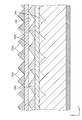
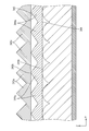
- FIG. 1 is an exploded perspective view showing a schematic configuration of a liquid crystal display device according to Embodiment 1 of the present invention.
- Exploded perspective view showing a schematic configuration of a backlight device constituting a liquid crystal display device
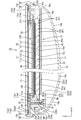
- Sectional drawing which shows the cross-sectional structure along the long side direction (1st direction, X-axis direction) in a liquid crystal display device.
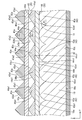
- Sectional drawing which shows the cross-sectional structure along the short side direction (2nd direction, Y-axis direction) in a liquid crystal display device.
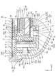
- Sectional view enlarging the vicinity of the LED in FIG.
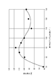
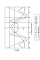
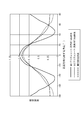
- the graph showing the luminance angle distribution in the second direction when the tangent angle in the cylindrical lens of the lenticular lens portion is changed The graph showing the relationship between the incident angle of the light with respect to a 1st prism sheet, and the outgoing angle of the light from a 1st prism sheet.
- the apex angle of the first unit prism of the first prism sheet was fixed at 90 °
- the apex angle of the second unit prism of the second prism sheet was changed within the range of 80 ° to 160 °.
- Sectional drawing which shows the cross-sectional structure along the short side direction (2nd direction, Y-axis direction) in the backlight apparatus which concerns on Embodiment 3 of this invention.
- Sectional drawing which shows the cross-sectional structure along the short side direction (2nd direction, Y-axis direction) in the backlight apparatus which concerns on Embodiment 4 of this invention.
- FIGS. 3 to 5 A first embodiment of the present invention will be described with reference to FIGS.
- the liquid crystal display device 10 is illustrated.
- a part of each drawing shows an X axis, a Y axis, and a Z axis, and each axis direction is drawn to be a direction shown in each drawing.
- FIGS. 3 to 5 are used as a reference, and the upper side of the figure is the front side and the lower side of the figure is the back side.
- the liquid crystal display device 10 has a rectangular shape as a whole as viewed in a plan view.
- the parts such as the casing 16 are assembled.
- the liquid crystal display unit LDU includes a liquid crystal panel (display panel) 11 having a display surface DS that displays an image on the front side, and a backlight device (illumination) that is disposed on the back side of the liquid crystal panel 11 and emits light toward the liquid crystal panel 11.
- Device 12 and a frame (housing member) 13 that holds the liquid crystal panel 11 from the front side, that is, the side opposite to the backlight device 12 side (display surface DS side).
- Both the touch panel 14 and the cover panel 15 are accommodated from the front side in the frame 13 constituting the liquid crystal display unit LDU, and the outer peripheral portion (including the outer peripheral end portion) is received from the back side by the frame 13.
- the touch panel 14 is disposed at a position at a predetermined interval on the front side with respect to the liquid crystal panel 11, and the back (inner side) plate surface is a facing surface that faces the display surface DS.
- the cover panel 15 is arranged so as to overlap the touch panel 14 on the front side, and the back (inner side) plate surface is a facing surface that is opposed to the front plate surface of the touch panel 14.
- An antireflection film AR is interposed between the touch panel 14 and the cover panel 15 (see FIG. 5).
- the casing 16 is assembled to the frame 13 so as to cover the liquid crystal display unit LDU from the back side.
- a part of the frame 13 (annular portion 13 b described later), the cover panel 15, and the casing 16 constitute the appearance of the liquid crystal display device 10.
- the liquid crystal display device 10 according to the present embodiment is used for an electronic device such as a tablet personal computer, and has a screen size of, for example, about 20 inches.
- the liquid crystal panel 11 constituting the liquid crystal display unit LDU will be described in detail.
- the liquid crystal panel 11 includes a pair of glass substrates 11a and 11b having a rectangular shape in plan view and substantially transparent and having excellent translucency, and both substrates 11a and 11b.
- a liquid crystal layer (not shown) containing liquid crystal molecules that are substances whose optical characteristics change with application of an electric field, and both substrates 11a and 11b maintain a gap corresponding to the thickness of the liquid crystal layer. In the state, they are bonded together by a sealing material not shown.
- the liquid crystal panel 11 includes a display area (a central part surrounded by a plate-surface light shielding layer 32 described later) and a non-display area (a board described later) that forms a frame surrounding the display area and does not display an image. And an outer peripheral portion overlapping with the surface light shielding layer 32.
- the long side direction in the liquid crystal panel 11 coincides with the X-axis direction
- the short side direction coincides with the Y-axis direction
- the thickness direction coincides with the Z-axis direction.
- the front side is the CF substrate 11a
- the back side is the array substrate 11b
- a number of TFTs Thin Film Transistors
- pixel electrodes which are switching elements
- a gate wiring and a source wiring having a lattice shape are disposed around the gate.
- a predetermined image signal is supplied to each wiring from a control circuit (not shown).
- the pixel electrode disposed in a rectangular region surrounded by the gate wiring and the source wiring is made of a transparent electrode such as ITO (Indium Tin Oxide) or ZnO (Zinc Oxide).
- CF substrate 11a On the other hand, on the CF substrate 11a, a large number of color filters are arranged side by side at positions corresponding to the respective pixels.
- the color filter is arranged so that three colors of R, G, and B are alternately arranged.
- a light shielding layer (black matrix) for preventing color mixture is formed between the color filters.
- On the surface of the color filter and the light shielding layer a counter electrode facing the pixel electrode on the array substrate 11b side is provided.
- the CF substrate 11a is slightly smaller than the array substrate 11b.
- An alignment film for aligning liquid crystal molecules contained in the liquid crystal layer is formed on the inner surfaces of both the substrates 11a and 11b. Note that polarizing plates 11c and 11d are attached to the outer surfaces of both the substrates 11a and 11b, respectively (see FIG. 5).
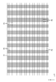
- one unit pixel PX which is a display unit is configured by a set of three colored portions of R (red), G (green), and B (blue) and three pixel electrodes facing them.
- the unit pixels PX are arranged in a matrix (matrix) in a large number along the plate surfaces of both the substrates 11a and 11b, that is, the display surface DS (X-axis direction and Y-axis direction).
- the unit pixel PX includes a red pixel having an R colored portion, a green pixel having a G colored portion, and a blue pixel having a B colored portion.
- the pixels of each color constitute a pixel group by being repeatedly arranged along the row direction (X-axis direction) on the plate surface of the liquid crystal panel 11, and this pixel group constitutes the column direction (Y-axis direction). Many are arranged side by side. Accordingly, it can be said that the unit pixels PX are periodic structures that are arranged in parallel with a certain periodicity along the X-axis direction and the Y-axis direction.
- FIG. 6 schematically shows the arrangement of the unit pixels PX in the liquid crystal panel 11.
- the backlight device 12 constituting the liquid crystal display unit LDU will be described in detail.
- the backlight device 12 has a generally rectangular block shape when viewed in plan as with the liquid crystal panel 11 as a whole.
- the backlight device 12 includes an LED (Light Emitting Diode) 17 that is a light source, an LED board (light source board) 18 on which the LED 17 is mounted, and light from the LED 17.
- a light guide plate 19 that guides light
- a reflection sheet (reflecting member) 40 that reflects light from the light guide plate 19, and an optical sheet (first anisotropic light condensing unit, second difference) arranged on the light guide plate 19.
- the backlight device 12 is an edge light type (side light type) of a one-side light incident type in which LEDs 17 (LED substrates 18) are unevenly distributed at one end portion on the short side of the outer peripheral portion. .
- the LED 17 has a configuration in which an LED chip is sealed with a resin material on a substrate portion fixed to the LED substrate 18, as shown in FIGS.
- the LED chip mounted on the substrate unit has one main emission wavelength, and specifically, one that emits blue light in a single color is used.
- the resin material that seals the LED chip is dispersed and blended with a phosphor that emits a predetermined color when excited by the blue light emitted from the LED chip, and generally emits white light as a whole. It is said.
- the phosphor for example, a yellow phosphor that emits yellow light, a green phosphor that emits green light, and a red phosphor that emits red light are used in appropriate combination, or any one of them is used. It can be used alone.
- the LED 17 is a so-called top surface light emitting type in which a surface opposite to the mounting surface with respect to the LED substrate 18 is a light emitting surface 17a.
- the LED substrate 18 has a long plate shape extending along the Y-axis direction (the short side direction of the light guide plate 19 and the chassis 22).
- the plate 22 is accommodated in the chassis 22 in a posture in which the plate surface is parallel to the Y-axis direction and the Z-axis direction, that is, a posture in which the plate surface is orthogonal to the plate surfaces of the liquid crystal panel 11 and the light guide plate 19. That is, the LED substrate 18 has a posture in which the long side direction on the plate surface coincides with the Y-axis direction, the short side direction coincides with the Z-axis direction, and the plate thickness direction orthogonal to the plate surface coincides with the X-axis direction. It is said.
- the LED board 18 has a plate surface (mounting surface 18 a) facing inward at a predetermined interval in the X-axis direction with respect to one short side end surface (light incident surface 19 b, light source facing end surface) of the light guide plate 19. It is arranged in an opposing manner while being vacant. Therefore, the alignment direction of the LED 17 and the LED substrate 18 and the light guide plate 19 is substantially coincident with the X-axis direction.
- the LED board 18 has a length that is approximately the same as or larger than the short side dimension of the light guide plate 19 and is attached to one end of the short side of the chassis 22 to be described later.
- the mounting surface 18a is used on the inner side of the LED substrate 18, that is, the plate surface facing the light guide plate 19 side (the surface facing the light guide plate 19), as shown in FIG.
- the mounting surface 18a is used.
- a plurality of LEDs 17 are arranged in a line (linearly) in parallel on the mounting surface 18a of the LED substrate 18 along the length direction (Y-axis direction) with a predetermined interval. That is, it can be said that a plurality of LEDs 17 are intermittently arranged in parallel along the short side direction at one end portion on the short side side of the backlight device 12.
- the arrangement interval (arrangement pitch) between adjacent LEDs 17 is substantially equal.
- a wiring pattern (not shown) made of a metal film (such as copper foil) is provided on the mounting surface 18a of the LED substrate 18 and extends in the Y-axis direction and connects adjacent LEDs 17 in series across the LED 17 group. And the terminal portions formed at both ends of the wiring pattern are connected to an external LED driving circuit, so that driving power can be supplied to each LED 17.
- the base material of the LED substrate 18 is made of metal like the chassis 22, and the wiring pattern (not shown) described above is formed on the surface thereof via an insulating layer.
- insulating materials such as a ceramic, can also be used as a material used for the base material of LED board 18.
- the light guide plate 19 is made of a synthetic resin material (for example, acrylic resin such as PMMA) having a refractive index sufficiently higher than that of air, almost transparent, and excellent in translucency. As shown in FIG. 2, the light guide plate 19 is a flat plate having a substantially rectangular shape in plan view, like the liquid crystal panel 11, and the plate surface is the plate surface (display surface DS) of the liquid crystal panel 11. Parallel.
- the light guide plate 19 has a long side direction on the plate surface corresponding to the X-axis direction, a short side direction corresponding to the Y-axis direction, and a plate thickness direction orthogonal to the plate surface corresponding to the Z-axis direction. As shown in FIGS.
- the light guide plate 19 is disposed in the chassis 22 at a position directly below the liquid crystal panel 11 and the optical sheet 20, and one of the outer peripheral end faces has an end face on the short side. 22, each LED 17 of the LED substrate 18 arranged at one end portion on the short side is opposed to each other. Therefore, while the alignment direction of the LED 17 (LED substrate 18) and the light guide plate 19 coincides with the X-axis direction, the alignment direction (overlapping direction) of the optical sheet 20 (liquid crystal panel 11) and the light guide plate 19 is Z. It is coincident with the axial direction, and both alignment directions are orthogonal to each other.
- the light guide plate 19 introduces light emitted from the LED 17 toward the light guide plate 19 along the X-axis direction (the alignment direction of the LED 17 and the light guide plate 19) from the end surface on the short side, and transmits the light. While propagating inside, it has a function of rising up toward the optical sheet 20 side (front side, light emitting side) and emitting from the plate surface.
- the plate surface facing the front side (the surface facing the liquid crystal panel 11 and the optical sheet 20) is configured to transmit internal light to the optical sheet as shown in FIGS. 20 and the light emission surface 19a to be emitted toward the liquid crystal panel 11 side.
- the outer peripheral end surfaces adjacent to the plate surface of the light guide plate 19, of the pair of short side end surfaces having a longitudinal shape along the Y-axis direction (LED 17 alignment direction, LED substrate 18 long side direction) As shown in FIG. 5, one end face (left side shown in FIG. 3) is opposed to the LED 17 (LED substrate 18) with a predetermined space therebetween, and light emitted from the LED 17 is incident thereon.
- the light incident surface 19b is a surface that is parallel to the Y-axis direction and the Z-axis direction, and is a surface that is substantially orthogonal to the light emitting surface 19a. Further, the alignment direction of the LED 17 and the light incident surface 19b (light guide plate 19) coincides with the X-axis direction and is parallel to the light emitting surface 19a. Of the pair of short-side end faces on the outer peripheral end face of the light guide plate 19, the other end face opposite to the above-described light incident face 19b (the end face opposite to the light incident face 19b) is the opposite end face 19d.
- a pair of long side end surfaces (a pair of end surfaces that form opposite sides and do not include the light incident surface 19b) adjacent to both the light incident surface 19b and the opposite end surface 19d are respectively side end surfaces 19e.
- the pair of side end surfaces 19e are parallel to the X-axis direction (the alignment direction of the LEDs 17 and the light guide plate 19) and the Z-axis direction.
- three end surfaces excluding the light incident surface 19b, that is, the opposite end surface 19d and the pair of side end surfaces 19e are not LED facing each other as shown in FIGS. It is set as a facing end surface (light source non-facing end surface).
- the light that has entered the light guide plate 19 from the LED 17 with respect to the light incident surface 19b that is the outer peripheral end surface of the light guide plate 19 is reflected by the reflection sheet 40 described below, or the light exit surface 19a, the opposite plate surface 19c, In addition, it is efficiently reflected in the light guide plate 19 by being totally reflected by the other outer peripheral end surfaces (the opposite end surface 19d and the side end surfaces 19e).
- the material of the light guide plate 19 is an acrylic resin such as PMMA
- the refractive index is about 1.49, so the critical angle is about 42 °, for example.
- a direction (X-axis direction) along a pair of end surfaces (long side end surface, side end surface 19 e) that form opposite sides and do not include the light incident surface 19 b is referred to as “first direction”. 1 direction ”, and a direction (Y-axis direction) along a pair of end faces (an end face on the short side, the light incident face 19b, and the opposite end face 19d) that form opposite sides and include the light incident face 19b is referred to as a“ second direction ”. .
- the opposite plate surface 19c opposite to the light exit surface 19a reflects the light from the light guide plate 19 to the front side, that is, the light exit, as shown in FIGS.
- a reflection sheet 40 that can be raised to the surface 19a side is provided so as to cover almost the entire area.
- the reflection sheet 40 is disposed between the bottom plate 22 a of the chassis 22 and the light guide plate 19.
- the reflection sheet 40 has a reflection surface 40a that opposes the opposite plate surface 19c of the light guide plate 19 and reflects light, and the reflected light from the reflection surface 40a can be efficiently propagated in the light guide plate 19. It is said.
- the end of the light guide plate 19 on the light incident surface 19b side is extended to the outside of the light incident surface 19b, that is, toward the LED 17, as shown in FIG.
- the opposite plate surface 19 c of the light guide plate 19 is provided with a reflection portion 41 for reflecting light propagating through the light guide plate 19 and promoting emission from the light emission surface 19 a. ing.
- the reflection portion 41 includes a groove-shaped unit reflection portion 41a that extends along the second direction (Y-axis direction) on the opposite plate surface 19c of the light guide plate 19 and has a substantially triangular (substantially V-shaped) cross-sectional shape. A plurality of intermittent arrangements are made in parallel along the first direction (X-axis direction).
- the unit reflecting portion 41 a includes an inclined surface 41 a 1 that is inclined with respect to the thickness direction of the light guide plate 19, that is, a direction orthogonal to both the first direction and the second direction (Z-axis direction), and the light guide plate 19.
- the parallel surface 41a2 parallel to the plate thickness direction is reflected, and light is reflected by the inclined surface 41a1 to generate light whose incident angle with respect to the light exit surface 19a does not exceed the critical angle. It is possible to prompt the emission from the emission surface 19a.
- the unit reflecting portions 41a are arranged such that the arrangement interval (arrangement pitch) gradually decreases as the distance from the LED 17 (light incident surface 19b) increases in the first direction, and the areas of the inclined surfaces 41a1 and the parallel surfaces 41a2 gradually increase. . Thereby, the emitted light from the light emitting surface 19a is controlled to have a uniform distribution in the surface of the light emitting surface 19a.
- the optical sheet 20 has a rectangular shape when seen in a plane, like the liquid crystal panel 11 and the chassis 22.
- the optical sheet 20 is arranged so as to cover the light emission surface 19a of the light guide plate 19 from the front side (light emission side), and is interposed between the liquid crystal panel 11 and the light guide plate 19, thereby providing the light guide plate.
- the light emitted from 19 is transmitted and emitted toward the liquid crystal panel 11 while giving a predetermined optical action to the transmitted light.
- the optical sheet 20 will be described in detail later.
- the light shielding frame 21 is formed in a substantially frame shape (frame shape) extending so as to follow the outer peripheral portion (outer peripheral end portion) of the light guide plate 19.
- the outer peripheral portion can be pressed from the front side over almost the entire circumference.
- the light-shielding frame 21 is made of synthetic resin and has a light-shielding property because the surface has a form of black, for example.
- the shading frame 21 is arranged such that its inner end 21 a is interposed over the entire circumference between the outer peripheral portion of the light guide plate 19 and the LED 17 and the outer peripheral portions (outer peripheral end portions) of the liquid crystal panel 11 and the optical sheet 20. They are partitioned so that they are optically independent.
- the light emitted from the LED 17 and not entering the light incident surface 19b of the light guide plate 19 or the light leaking from the opposite end surface 19d and the side end surface 19e is the outer peripheral portion (particularly the end surface) of the liquid crystal panel 11 and the optical sheet 20. ) Can be shielded from direct incident light.
- the light shielding frame 21 three side portions (a pair of long side portions and a short side portion opposite to the LED substrate 18 side) that do not overlap with the LED 17 and the LED substrate 18 in plan view are chassis. 22 has a portion that rises from the bottom plate 22a and a portion that supports the frame 13 from the back side, but the short side portion that overlaps the LED 17 and the LED substrate 18 in a plan view is the end of the light guide plate 19.
- the LED board 18 (LED 17) are covered from the front side and bridged between a pair of long sides.
- the light shielding frame 21 is fixed to a chassis 22 described below by fixing means such as a screw member (not shown).
- the chassis 22 is made of a metal plate having excellent thermal conductivity, such as an aluminum plate or an electrogalvanized steel plate (SECC), and is rectangular in a plan view like the liquid crystal panel 11 as shown in FIGS.
- a bottom plate 22a having a shape and a side plate 22b rising from the outer end of each side (a pair of long sides and a pair of short sides) of the bottom plate 22a toward the front side.
- the chassis 22 (bottom plate 22a) has a long side direction that matches the X-axis direction, and a short side direction that matches the Y-axis direction.
- the bottom plate 22a is a light guide plate support portion 22a1 that supports the light guide plate 19 from the back side (the side opposite to the light emitting surface 19a side), whereas the end on the LED substrate 18 side is stepped.
- the board accommodating portion 22a2 bulges to the back side.
- the substrate housing portion 22a2 has a substantially L-shaped cross-section, is bent from the end portion of the light guide plate support portion 22a1, and rises toward the back side, and a rising portion. It is composed of a receiving bottom 39 that is bent from the rising tip of 38 and protrudes toward the side opposite to the light guide plate support 22a1 side.
- the bent position of the rising portion 38 from the end of the light guide plate support portion 22a1 is located on the opposite side of the light incident surface 19b of the light guide plate 19 from the LED 17 side (near the center of the light guide plate support portion 22a1). .
- a long side side plate 22b is bent from the protruding tip of the housing bottom 39 so as to rise to the front side.
- the LED substrate 18 is attached to the side plate 22b on the short side continuous to the substrate housing portion 22a2, and the side plate 22b constitutes the substrate attachment portion 37.
- the board mounting portion 37 has a facing surface that faces the light incident surface 19b of the light guide plate 19, and the LED substrate 18 is mounted on the facing surface.
- the LED substrate 18 is fixed in such a manner that the plate surface opposite to the mounting surface 18a on which the LED 17 is mounted is in contact with the inner plate surface of the substrate mounting portion 37 via a substrate fixing member 25 such as a double-sided tape. ing.
- the attached LED board 18 has a slight gap between the LED board 18 and the inner plate surface of the housing bottom 39 that forms the board housing 22a2.
- a liquid crystal panel drive circuit board (not shown) for controlling the drive of the liquid crystal panel 11, and an LED drive circuit board (not shown) for supplying drive power to the LEDs 17.
- a touch panel drive circuit board (not shown) for controlling the drive of the touch panel 14 is attached.
- the heat dissipating member 23 is made of a metal plate having excellent thermal conductivity such as an aluminum plate. As shown in FIG. 3, the heat dissipating member 23 is formed on one end of the short side of the chassis 22, specifically, on a substrate housing portion 22 a 2 that houses the LED substrate 18. It is set as the form extended along. As shown in FIG. 5, the heat dissipating member 23 has a substantially L-shaped cross section, and is parallel to the outer surface of the substrate housing portion 22a2 and in contact with the outer surface, and the substrate housing portion 22a2. It consists of the 2nd thermal radiation part 23b parallel to the outer surface of the continuous side plate 22b (board
- the first heat radiating portion 23a has an elongated flat plate shape extending along the Y-axis direction, and the plate surface facing the front side parallel to the X-axis direction and the Y-axis direction has a receiving bottom portion 39 in the substrate receiving portion 22a2. It is contact
- the first heat radiating portion 23a is screwed to the housing bottom 39 by a screw member SM, and has a screw insertion hole 23a1 through which the screw member SM is inserted.
- the accommodation bottom 39 is formed with a screw hole 28 into which the screw member SM is screwed.
- the second heat dissipating part 23b has an elongated flat plate shape extending along the Y-axis direction, and a plate surface facing inward in parallel to the Y-axis direction and the Z-axis direction is an outer plate in the board mounting part 37. They are arranged in a facing manner with a predetermined gap between them and the surface.
- the frame 13 constituting the liquid crystal display unit LDU will be described.
- the frame 13 is made of a metal material having excellent thermal conductivity such as aluminum.
- each outer peripheral portion (outer periphery) of the liquid crystal panel 11, the touch panel 14 and the cover panel 15 is used.
- it has a substantially rectangular frame shape (frame shape).
- press working or the like is employed as a method for manufacturing the frame 13, for example.
- the frame 13 presses the outer peripheral portion of the liquid crystal panel 11 from the front side, and the liquid crystal panel 11 and the optical sheet stacked with each other with the chassis 22 constituting the backlight device 12.
- the frame 13 receives the outer peripheral portions of the touch panel 14 and the cover panel 15 from the back side, and is arranged in a form interposed between the outer peripheral portions of the liquid crystal panel 11 and the touch panel 14.
- a predetermined gap is secured between the liquid crystal panel 11 and the touch panel 14.
- the touch panel 14 follows the cover panel 15 toward the liquid crystal panel 11. Even when it is deformed to bend, the bent touch panel 14 is less likely to interfere with the liquid crystal panel 11.
- the frame 13 includes a frame-shaped portion (frame base portion, frame-shaped portion) 13 a that follows the outer peripheral portions of the liquid crystal panel 11, the touch panel 14, and the cover panel 15, and the outer periphery of the frame-shaped portion 13 a. Attached to the chassis 22 and the heat radiating member 23 projecting from the frame-shaped part 13a toward the back side, and an annular part (cylindrical part) 13b that continues to the end and surrounds the touch panel 14, the cover panel 15 and the casing 16 from the outer peripheral side. And an attachment plate portion 13c.
- the frame-like portion 13a has a substantially plate shape having plate surfaces parallel to the plate surfaces of the liquid crystal panel 11, the touch panel 14, and the cover panel 15, and is formed in a rectangular frame shape when viewed from above.
- the frame portion 13a is relatively thicker at the outer peripheral portion 13a2 than at the inner peripheral portion 13a1, and a step (gap) GP is formed at the boundary between them.
- the inner peripheral portion 13a1 is interposed between the outer peripheral portion of the liquid crystal panel 11 and the outer peripheral portion of the touch panel 14, whereas the outer peripheral portion 13a2 receives the outer peripheral portion of the cover panel 15 from the back side. .
- the front plate surface of the frame-like portion 13a is almost entirely covered by the cover panel 15, the front plate surface is hardly exposed to the outside. Thereby, even if the temperature of the frame 13 is increased due to heat from the LED 17 or the like, it is difficult for the user of the liquid crystal display device 10 to directly contact the exposed portion of the frame 13, which is excellent in terms of safety.
- a buffer material 29 for fixing the outer peripheral portion of the liquid crystal panel 11 from the front side while buffering is fixed.
- the first fixing member 30 for fixing the outer peripheral portion of the touch panel 14 while buffering the outer peripheral portion of the touch panel 14 is fixed to the front plate surface of the inner peripheral portion 13a1.
- the cushioning material 29 and the first fixing member 30 are arranged at positions overlapping each other in the inner peripheral portion 13a1 when viewed in plan.
- a second fixing member 31 for fixing the outer peripheral portion of the cover panel 15 while buffering the outer peripheral portion of the cover panel 15 is fixed to the front plate surface of the outer peripheral portion 13a2 of the frame-like portion 13a.
- the buffer material 29 and the fixing members 30 and 31 are arranged so as to extend along the side portions of the frame-like portion 13a excluding the corner portions at the four corners.
- each fixing member 30 and 31 consists of a double-sided tape in which a base material has cushioning properties, for example.
- the annular portion 13 b has a rectangular short rectangular tube shape as viewed in plan as a whole, and protrudes from the outer peripheral edge of the outer peripheral portion 13 a 2 of the frame-shaped portion 13 a toward the front side. It has the 1st annular part 34 and the 2nd annular part 35 which protrudes toward the back side from the outer periphery of the outer peripheral part 13a2 of the frame-shaped part 13a.
- the outer peripheral edge of the frame-shaped portion 13a is connected to the inner peripheral surface at the substantially central portion in the axial direction (Z-axis direction) over the entire periphery.
- the first annular portion 34 is arranged so as to surround the outer peripheral end surfaces of the touch panel 14 and the cover panel 15 arranged on the front side with respect to the frame-shaped portion 13a over the entire circumference.
- the first annular portion 34 has an inner peripheral surface facing each outer peripheral end surface of the touch panel 14 and the cover panel 15, whereas the outer peripheral surface is exposed to the outside of the liquid crystal display device 10, and the liquid crystal display The external appearance of the side surface side of the device 10 is configured.
- the second annular portion 35 surrounds the front end portion (attachment portion 16c) of the casing 16 disposed on the back side with respect to the frame-shaped portion 13a from the outer peripheral side.
- the second annular portion 35 has an inner peripheral surface facing a mounting portion 16c of the casing 16 described later, whereas an outer peripheral surface is exposed to the outside of the liquid crystal display device 10 and the liquid crystal display device 10.
- the external appearance of the side of the A frame-side hooking claw portion 35a having a cross-sectional saddle shape is formed at the projecting tip portion of the second annular portion 35, and the casing 16 is locked to the frame-side locking claw portion 35a.
- the casing 16 can be held in the attached state.
- the mounting plate portion 13c protrudes from the outer peripheral portion 13a2 toward the back side of the frame-shaped portion 13a and extends along each side of the frame-shaped portion 13a.
- the plate surface is substantially orthogonal to the plate surface of the frame-like portion 13a.
- the mounting plate portion 13c is individually arranged for each side portion of the frame-like portion 13a.
- the mounting plate portion 13c disposed on the short side portion on the LED substrate 18 side of the frame-shaped portion 13a is such that the plate surface facing the inside contacts the outer plate surface of the second heat radiating portion 23b of the heat radiating member 23. It is attached.
- the mounting plate portion 13c is screwed to the second heat radiating portion 23b by a screw member SM, and has a screw insertion hole 13c1 through which the screw member SM is inserted. Further, a screw hole 36 into which the screw member SM is screwed is formed in the second heat radiating portion 23b. Thereby, the heat from the LED 17 transmitted from the first heat radiating portion 23a to the second heat radiating portion 23b is transmitted to the entire plate 13 after being transmitted to the mounting plate portion 13c. Heat is dissipated. Further, it can be said that the mounting plate portion 13 c is indirectly fixed to the chassis 22 via the heat radiating member 23.
- each of the mounting plate portions 13c disposed on the short side portion and the pair of long side portions on the opposite side to the LED substrate 18 side of the frame-like portion 13a has a plate surface facing the inner side of each of the chassis 22.
- Each of the side plates 22b is screwed with a screw member SM so as to be in contact with the outer plate surface.
- the mounting plate portions 13c are formed with screw insertion holes 13c1 through which the screw members SM are inserted, whereas the side plates 22b are formed with screw holes 36 into which the screw members SM are screwed. .
- Each screw member SM is attached to each attachment plate portion 13c in a form where a plurality of screw members SM are intermittently arranged along the extending direction.
- the touch panel 14 is a position input device for a user to input position information within the surface of the display surface DS of the liquid crystal panel 11, and has a rectangular shape and is almost the same.
- a predetermined touch panel pattern (not shown) is formed on a glass substrate having transparency and excellent translucency.
- the touch panel 14 has a glass substrate that has a rectangular shape when seen in a plan view like the liquid crystal panel 11, and a so-called projected capacitive touch panel pattern is provided on the surface facing the front side.
- a transparent electrode portion (not shown) for the touch panel is formed, and a large number of the transparent electrode portions for the touch panel are arranged in parallel in a matrix within the surface of the substrate.
- a terminal portion (not shown) connected to the end portion of the wiring drawn from the transparent electrode portion for the touch panel constituting the touch panel pattern is formed at one end portion on the short side of the touch panel 14.
- a flexible substrate not shown
- a potential is supplied from the touch panel drive circuit substrate to the transparent electrode portion for the touch panel forming the touch panel pattern.
- the touch panel 14 is fixed in a state where the inner plate surface in the outer peripheral portion thereof is opposed to the inner peripheral portion 13 a 1 in the frame-like portion 13 a of the frame 13 by the first fixing member 30 described above. Has been.
- the cover panel 15 assembled to the frame 13 will be described.
- the cover panel 15 is disposed so as to cover the touch panel 14 from the front side over the entire region, thereby protecting the touch panel 14 and the liquid crystal panel 11.
- the cover panel 15 covers the entire frame-like portion 13a of the frame 13 from the front side to the entire area, and configures the appearance of the front side of the liquid crystal display device 10.
- the cover panel 15 has a rectangular shape when seen in a plan view and is made of a plate-like base material made of glass that is substantially transparent and has excellent translucency, and preferably made of tempered glass.
- the tempered glass used for the cover panel 15 it is preferable to use chemically tempered glass having a chemically strengthened layer on the surface, for example, by subjecting the surface of a plate-like glass substrate to chemical strengthening treatment.
- This chemical strengthening treatment refers to, for example, a treatment for strengthening a plate-like glass substrate by replacing alkali metal ions contained in a glass material by ion exchange with alkali metal ions having an ion radius larger than that,
- the resulting chemically strengthened layer is a compressive stress layer (ion exchange layer) in which compressive stress remains.
- the cover panel 15 has a rectangular shape when viewed in a plane, similar to the liquid crystal panel 11 and the touch panel 14, and the size viewed in the plane is larger than that of the liquid crystal panel 11 and the touch panel 14. Is a little bigger. Therefore, the cover panel 15 has an overhanging portion 15EP that projects outwardly in a bowl shape from the outer peripheral edges of the liquid crystal panel 11 and the touch panel 14 over the entire circumference.
- This overhanging portion 15EP has a substantially rectangular frame shape (substantially frame shape) surrounding the liquid crystal panel 11 and the touch panel 14, and the inner plate surface thereof has the second fixing described above as shown in FIG.
- the member 31 is fixed to the outer peripheral portion 13a2 of the frame-like portion 13a of the frame 13 so as to face the outer peripheral portion 13a2.
- a central portion of the cover panel 15 that faces the touch panel 14 is laminated on the front side with respect to the touch panel 14 via an antireflection film AR.
- a light-blocking plate is provided on the inner (back side) plate surface (the plate surface facing the touch panel 14) in the outer peripheral portion including the above-described overhang portion 15 EP of the cover panel 15.
- a surface light shielding layer (light shielding layer, plate surface light shielding portion) 32 is formed.
- the plate surface light shielding layer 32 is made of a light shielding material such as a paint exhibiting black, for example, and the light shielding material is integrally provided on the plate surface by printing on the inner plate surface of the cover panel 15. It has been.
- printing means such as screen printing and ink jet printing can be employed.
- the plate surface light shielding layer 32 is inside the overhanging portion 15EP in addition to the entire overhanging portion 15EP of the cover panel 15, and overlaps with each of the outer peripheral portions of the touch panel 14 and the liquid crystal panel 11 in a plan view. It is formed in a range over the part to be. Therefore, the plate surface light shielding layer 32 is arranged so as to surround the display area of the liquid crystal panel 11, so that the light outside the display area can be blocked, and thus the display quality relating to the image displayed in the display area. Can be high.
- the casing 16 is made of a synthetic resin material or a metal material, and as shown in FIGS. 1, 3, and 4, has a substantially bowl shape that opens toward the front side. 13 covers the members such as the frame-shaped portion 13a, the mounting plate portion 13c, the chassis 22, and the heat dissipation member 23 from the back side, and configures the appearance of the back side of the liquid crystal display device 10.
- the casing 16 has a generally flat bottom portion 16a, a curved portion 16b that rises from the outer peripheral edge of the bottom portion 16a to the front side and has a curved cross section, and an attachment portion that rises almost straight from the outer peripheral edge of the curved portion 16b to the front side.
- the attachment portion 16c is formed with a casing-side locking claw portion 16d having a saddle-shaped cross section.
- the casing-side locking claw portion 16d is locked to the frame-side locking claw portion 35a of the frame 13.
- the casing 16 can be held in the attached state with respect to the frame 13.
- the backlight device 12 has a configuration for condensing the emitted light from the light emitting surface 19a of the light guide plate 19 in the second direction (Y-axis direction).
- the configuration will be described.
- the light propagating through the light guide plate 19 is reflected and raised by the inclined surface 41 a 1 of the unit reflecting portion 41 a that constitutes the reflecting portion 41 in the middle, thereby emitting light.
- the incident angle with respect to the surface 19a is emitted at a critical angle or less, and the first direction (X-axis direction) is raised by the unit reflecting portion 41a in the front direction, that is, from the light emitting surface 19a.
- Condensation is intended to go in the direction toward the front side along the normal direction.
- the reflecting portion 41 gives a condensing function to the reflected light in the first direction, it hardly gives a condensing effect to the reflected light in the second direction, so that it is related to the outgoing light from the light emitting surface 19a.
- a lenticular lens portion 42 is provided, and the optical sheet 20 includes unit prisms 43a. It is composed of two prism sheets 43 and 44 in which a plurality of 44a are arranged in parallel along the second direction. Next, the lenticular lens unit 42 and the two prism sheets 43 and 44 will be described in detail.
- the lenticular lens unit 42 includes a plurality of cylindrical lenses 42 a having a substantially semi-cylindrical shape extending along the first direction on the light exit surface 19 a of the light guide plate 19. ) In parallel with each other along the second direction.
- the lenticular lens portion 42 is provided integrally with the light guide plate 19.
- the light guide plate 19 is manufactured by injection molding, and a transfer shape for transferring the lenticular lens portion 42 in advance is formed on the molding surface of the molding die. Just keep it.
- the cylindrical lens 42a has a substantially semicircular shape (a saddle-shaped) cross-section cut along a parallel direction (second direction) orthogonal to the extending direction (first direction), and the light in the cylindrical lens 42a. Is incident on the outer surface (interface) having an arc shape with an incident angle greater than the critical angle, the light is totally reflected by the outer surface having the arc shape so that the inside of the cylindrical lens 42a extends along the first direction. By proceeding, it is possible to diffuse light in the first direction. Thereby, the brightness nonuniformity which may arise in the emitted light from the light-projection surface 19a can be reduced. This luminance unevenness suppressing effect varies depending on the shape of the cylindrical lens 42a, and will be described below with a specific example.
- the angle ⁇ t formed by the tangent line Ta at the base end portion 42a1 of the outer surface forming an arc shape in the cylindrical lens 42a with respect to the second direction is defined as a “tangential angle”.
- Light guide plates 19 each having a lenticular lens portion 42 composed of a cylindrical lens 42a with angles ⁇ t of 20 °, 30 °, 40 °, 60 °, and 70 ° are prepared, and the LEDs 17 are turned on to emit light from each light guide plate 19.
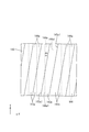
- FIG. 8 shows a photograph taken from the light emitting surface 19a side in a state where light is emitted from each light guide plate 19 having a tangent angle ⁇ t of 20 °, 30 °, 40 °, 60 °, and 70 °, and the photograph. And luminance unevenness determination results based on the above.
- the cylindrical lens 42a preferably has a tangent angle ⁇ t of 40 ° or more.
- the lenticular lens unit 42 according to the present embodiment is also configured such that the tangent angle ⁇ t in the cylindrical lens 42a is 40 ° or more (for example, 70 °).
- the second direction is the light collection direction of the cylindrical lens 42a.
- the light passing through the focal point of the cylindrical lens 42a can be refracted by the arc-shaped outer surface to be emitted as light substantially parallel to the front direction.
- the condensing effect which selectively raises the light which goes to a 2nd direction among the emitted light from the light-projection surface 19a, and makes the advancing direction face the front direction (approaching) is acquired.
- This condensing effect does not vary so much depending on the shape of the cylindrical lens 42a.
- the light guide plates 19 each including the lenticular lens portion 42 including the cylindrical lens 42a having tangent angles ⁇ t of 15 °, 30 °, 47.5 °, 60 °, and 70 ° in the cylindrical lens 42a are provided.
- An experiment for preparing and measuring the luminance of the light emitted from each light guide plate 19 is performed, and the result of the experiment is shown in the graph of FIG. The graph shown in FIG.
- FIG. 9 shows the luminance angle distribution in the second direction related to the light emitted from each light guide plate 19.
- the vertical axis represents the relative luminance (no unit) of the light emitted from the light guide plate 19
- the horizontal axis represents the angle (unit: “°”) with respect to the front direction in the second direction.
- the relative luminance on the vertical axis in FIG. 9 is a relative value with the luminance value in the front direction (angle 0 °) as the reference (1.0). According to FIG. 9, it can be seen that the luminance angle distribution becomes the most gentle when the tangent angle ⁇ t is 15 °, but the luminance angle distribution is almost the same for other cases regardless of the magnitude of the tangent angle ⁇ t.
- the lenticular lens portion 42 is provided on the light exit surface 19a of the light guide plate 19, it can be said that a light collecting effect of a certain level or more can be obtained regardless of the shape (tangential angle ⁇ t) of the cylindrical lens 42a. .
- the optical sheet 20 includes two prism sheets 43 and 44, and the first prism is arranged on the opposite side (front side) from the light guide plate 19 side.
- the second prism sheet (second anisotropy) 43 is a sheet (first anisotropy condensing part) 43 and is disposed on the light guide plate 19 side and interposed between the first prism sheet 43 and the light guide plate 19. Condensing part) 44.
- the first prism sheet 43 includes a sheet-shaped first base material 43b, and a light incident side plate surface 43b1 on which light from the second prism sheet 44 of the first base material 43b is incident.
- the first base material 43b is made of a substantially transparent synthetic resin, specifically made of a thermoplastic resin material such as PET, and has a refractive index of about 1.667, for example.
- the first unit prism 43a is integrally provided on the light output side plate surface 43b2, which is the front plate surface of the first base material 43b.
- the first unit prism 43a is made of a substantially transparent ultraviolet curable resin material which is a kind of photocurable resin material. When the first prism sheet 43 is manufactured, for example, an uncured ultraviolet curable resin material is used for molding.
- the mold is filled and the first base material 43b is directed to the opening end of the mold so that the uncured ultraviolet curable resin material is disposed in contact with the light-emitting side plate surface 43b2, and the first base is in that state.
- the ultraviolet curable resin material can be cured and the first unit prism 43a can be provided integrally with the first base material 43b.
- the ultraviolet curable resin material forming the first unit prism 43a is, for example, an acrylic resin such as PMMA, and the refractive index thereof is, for example, about 1.59.
- the first unit prism 43a is provided so as to protrude from the light output side plate surface 43b2 of the first base material 43b toward the front side (the side opposite to the second prism sheet 44 side) along the Z-axis direction.
- the first unit prism 43a has a cross-sectional shape cut along the second direction (Y-axis direction) forming a substantially triangular shape (substantially mountain shape) and linearly extends along the first direction (X-axis direction).
- a plurality of light emitting side plate surfaces 43b2 are arranged in parallel along the second direction.
- Each of the first unit prisms 43a has a substantially isosceles triangular cross section, has a pair of inclined surfaces 43a1, and has an apex angle ⁇ v1 of approximately a right angle (90 °).
- the multiple first unit prisms 43a arranged in parallel along the second direction have the apex angle ⁇ v1 and the width and height dimensions of the bottom surface 43a2 that are substantially the same, and are arranged between adjacent first unit prisms 43a.
- the intervals are substantially constant and are arranged at equal intervals.
- the light When light is incident on the first prism sheet 43 configured as described above from the second prism sheet 44 side, the light is incident on the second unit prisms 44a of the second prism sheet 44 and the second prisms 44a as shown in FIG. Since the light enters the light incident side plate surface 43b1 of the first base material 43b from the air layer between the first prism sheet 43 and the first base material 43b, the light is refracted at the interface according to the incident angle.
- the light transmitted through the first base material 43b enters the first unit prism 43a from the light output side plate surface 43b2 of the first base material 43b, it is also refracted at the interface according to the incident angle.
- the light transmitted through the first unit prism 43a reaches the slope 43a1 of the first unit prism 43a, if the incident angle exceeds the critical angle, the light is totally reflected and returned to the first base material 43b side. On the other hand, if the incident angle does not exceed the critical angle, the light is emitted while being refracted at the interface. Of the light emitted from the inclined surface 43a1 of the first unit prism 43a, the light directed to the adjacent first unit prism 43a enters the first unit prism 43a and returns to the first base material 43b side. As a result, the outgoing light from the first unit prism 43a is regulated so that the traveling direction is close to the front direction in the second direction, so that a condensing action is selectively given in the second direction. .
- the second prism sheet 44 is opposite to the sheet-like second base material 44b and the light incident side plate surface 44b1 on which light from the light guide plate 19 enters the second base material 44b.
- the second unit prism 44a is formed on the light output side plate surface 44b2 on the side (first prism sheet 43 side) and has condensing anisotropy.
- the second base material 44b is made of a substantially transparent synthetic resin, specifically made of a thermoplastic resin material such as PET, and has a refractive index of about 1.667, for example. In the present embodiment, the second base material 44 b has substantially the same refractive index as that of the first base material 43.
- the second unit prism 44a is integrally provided on the light output side plate surface 44b2, which is the front plate surface of the second base material 44b.
- the second unit prism 44a is made of a substantially transparent ultraviolet curable resin material, which is a kind of photocurable resin material.
- an uncured ultraviolet curable resin material is used for molding.
- the mold is filled and the second base material 44b is directed to the opening end of the mold so that the uncured ultraviolet curable resin material is arranged in contact with the light-emitting side plate surface 44b2, and the second substrate is in that state.
- the ultraviolet curable resin material By irradiating the ultraviolet curable resin material with ultraviolet rays through the material 44b, the ultraviolet curable resin material can be cured and the second unit prism 44a can be provided integrally with the second substrate 44b.
- the ultraviolet curable resin material forming the second unit prism 44a is, for example, an acrylic resin such as PMMA, and the refractive index thereof is, for example, about 1.59.
- the second unit prism 44a has substantially the same refractive index as that of the first unit prism 43a.
- the second unit prism 44a is provided so as to protrude from the light output side plate surface 44b2 of the second base material 44b toward the front side (the side opposite to the light guide plate 19 side) along the Z-axis direction.
- the second unit prism 44a has a cross-sectional shape cut along the second direction (Y-axis direction) forming a substantially triangular shape (substantially mountain-shaped) and linearly extends along the first direction (X-axis direction).
- a plurality of light emitting side plate surfaces 44b2 are arranged in parallel along the second direction.
- Each of the second unit prisms 44a has a substantially isosceles triangular cross section, has a pair of inclined surfaces 44a1, and has an apex angle ⁇ v2 of an obtuse angle, specifically about 110 °. That is, the apex angle ⁇ v2 of the second unit prism 44a is relatively larger than the apex angle ⁇ v1 of the first unit prism 43a.
- the multiple second unit prisms 44a arranged in parallel along the second direction all have substantially the same apex angle ⁇ v2 and width and height dimensions of the bottom surface, and are arranged at intervals between the adjacent second unit prisms 44a. Are arranged at regular intervals.
- the second unit prism 44a has a width dimension and an arrangement interval substantially the same as the first unit prism 43a, but a height dimension smaller than that of the first unit prism 43a.
- the light When light is incident on the second prism sheet 44 having such a configuration from the light guide plate 19 side, the light is transmitted between the lenticular lens portion 42 of the light guide plate 19 and the second prism sheet 44 as shown in FIG. Is incident on the light incident side plate surface 44b1 of the second base member 44b, and is refracted at the interface according to the incident angle.
- the light transmitted through the second base material 44b enters the second unit prism 44a from the light output side plate surface 44b2 of the second base material 44b, it is also refracted at the interface according to the incident angle.
- the light transmitted through the second unit prism 44a reaches the inclined surface 44a1 of the second unit prism 44a, if the incident angle exceeds the critical angle, the light is totally reflected and returned to the second substrate 44b side. On the other hand, if the incident angle does not exceed the critical angle, the light is emitted while being refracted at the interface. Of the light emitted from the inclined surface 44a1 of the second unit prism 44a, the light directed toward the adjacent second unit prism 44a enters the second unit prism 44a and is returned to the second substrate 44b side. As a result, the outgoing light from the second unit prism 44a is regulated so that the traveling direction is close to the front direction in the second direction, so that a condensing action is selectively given in the second direction. .
- the second unit prism 44a constituting the second prism sheet 44 constitutes the first prism sheet 43 as shown in FIG. 7, and the first unit prism 43a having the apex angle ⁇ v1 of approximately 90 °. Since the apex angle ⁇ v2 is relatively larger than that of the first unit prism 43a, the condensing action imparted to the emitted light is relatively weaker. Specifically, when the light in each of the unit prisms 43a and 44a is emitted from each of the inclined surfaces 43a1 and 44a1, there is something that is directed to the adjacent unit prisms 43a and 44a, and such light is adjacent to each other.
- the light enters the matching unit prisms 43a and 44a and returns to the bases 43b and 44b.
- the amount of light returned tends to decrease as the apex angle increases beyond 90 °.
- the second unit prism 44a has a relatively small amount of returned light as compared with the first unit prism 43a.
- the amount of light emitted from each of the unit prisms 43a, 44a tends to increase as the apex angle increases beyond 90 °. Therefore, the second unit prism 44a is relatively more in comparison with the first unit prism 43a.
- the emitted light tends to include more light whose traveling direction is larger than the front direction.
- the second prism sheet 44 is provided on the light emitting surface 19a of the light guide plate 19 although the light condensing action applied to the emitted light is relatively weak compared to the first prism sheet 43.
- the light condensing action is relatively strong. The reason is that since the cylindrical lens 42a constituting the lenticular lens portion 42 is a curved surface having an outer surface formed in an arc shape, the emitted light is diffused as compared with the inclined surface 44a1 of the second unit prism 44a in the second prism sheet 44. This is because it tends to be easy.
- the light condensing structure that selectively condenses the light emitted from the light guide plate 19 in the second direction has a three-layer structure in which the light is laminated, and approaches the light guide plate 19.
- the condensing action imparted to the emitted light is weaker as the distance from the light guide plate 19 increases, and the condensing action imparted to the emitted light is stronger.
- the second prism sheet 44 includes the second unit prism 44 a so that the emitted light supplied toward the first prism sheet 43 includes a lot of light emitted without being retroreflected by the first prism sheet 43.
- the apex angle ⁇ v2 is larger than the apex angle ⁇ v1 of the first unit prism 43a.
- the apex angle ⁇ v1 of the first unit prism 43a is about 90 °, whereas the apex angle ⁇ v1 of the first unit prism 43a is about 90 °.
- the apex angle ⁇ v2 is about 110 °.
- the light emission angle from the light incident side plate surface 43b1 is obtained from the light incident angle with respect to the light incident side plate surface 43b1, and then the light emission angle from the light incident side plate surface 43b1 is Since it is equal to the incident angle of the light with respect to the light emission side plate surface 43b2 and the bottom surface 43a2 of the first unit prism 43a, the light emission angle from the light emission side plate surface 43b2 and the bottom surface 43a2 of the first unit prism 43a is obtained.
- the light exit angle from the light exit side plate surface 43b2 and the bottom surface 43a2 of the first unit prism 43a is equal to the light incident angle with respect to the inclined surface 43a1 of the first unit prism 43a.
- the light emission angle from the inclined surface 43a1 is obtained.
- the refractive indexes of the first base material 43b and the first unit prism 43a and the apex angle ⁇ v1 of the first unit prism 43a are as described above, and the refractive index of the external air layer is “1. Calculation is performed as “0”.
- the vertical axis represents the incident angle of light (unit: “°”) with respect to the light incident side plate surface 43b1 of the first base material 43b
- the horizontal axis represents the light emission angle from the inclined surface 43a1 of the first unit prism 43a. (The unit is “°”), and an emission angle of 0 ° is an emission angle of light parallel to the front direction. According to FIG.
- the light emission angle from the inclined surface 43a1 of the first unit prism 43a within a range of ⁇ 10 °, for example, the light incident angle with respect to the light incident side plate surface 43b1 of the first base material 43b. It can be seen that the range of 23 ° to 40 ° is sufficient.
- the light supplied to the first prism sheet 43 that is, the light emitted from the second unit prism 44a of the second prism sheet 44 has an emission angle in the range of 23 ° to 40 °.
- the emitted light from the first unit prism 43a of the first prism sheet 43 is emitted with an emission angle that is in a range of ⁇ 10 ° with respect to the front direction, and the front luminance of the emitted light is increased. It is useful for improvement.
- Comparative Experiments 1 and 2 are conducted to obtain knowledge about how the front luminance of the emitted light changes when the apex angles ⁇ v1 and ⁇ v2 of the first unit prism 43a and the second unit prism 44a are changed. Went to each.
- Comparative Experiment 1 First, Comparative Experiment 1 will be described.
- the apex angle ⁇ v1 of the first unit prism 43a in the first prism sheet 43 is fixed to 90 °, and the apex angle ⁇ v2 of the second unit prism 44a in the second prism sheet 44 is set to 80 ° to 160 °.
- luminance which concerns on the emitted light of the 1st prism sheet 43 is measured, changing within the range, and the experimental result is shown in FIG.
- the apex angle ⁇ v2 of the second unit prism 44a is 80 °, 90 °, 95 °, 100 °, 105 °, 110 °, 115 °, 120 °, 130 °, 132.5 °
- Second prism sheets 44 having 135 °, 137.5 °, 140 °, 145 °, 150 °, and 160 ° are prepared, and the apex angle ⁇ v1 is 90 ° on the front side with respect to each second prism sheet 44.
- the first prism sheet 43 including the first unit prism 43a is disposed, and the light guide plate 19 including the lenticular lens unit 42 is disposed on the back side, and then the LED 17 is turned on to relate to the emitted light from the first prism sheet 43
- the brightness is measured.
- the vertical axis represents the relative luminance (unit: “%”) of the light emitted from the first prism sheet 43
- the horizontal axis represents the apex angle ⁇ v 2 (unit: “%”) of the second unit prism 44 a of the second prism sheet 44. ° ”).
- the second prism sheet 44 in which the apex angles of the second unit prisms 44a are 80 ° and 90 ° is a comparative example.
- the apex angle ⁇ v2 of the second unit prism 44a is 90 ° or 80 ° and is less than 92 °, the brightness of the emitted light is lower than that in the case where the second prism sheet 44 is not used. The significance of using the prism sheet 44 is lost.
- the apex angle ⁇ v2 of the second unit prism 44a exceeds 140 °, the luminance of the emitted light tends to gradually decrease. At 160 °, the luminance of the emitted light is almost 100%. If the angle exceeds 60 °, it is considered that the luminance of the emitted light is lower than when the second prism sheet 44 is not used.
- the outgoing angle of the outgoing light from the second unit prism 44a is in the range of 23 ° to 40 °.
- the second prism sheet 44 is included in a larger amount than when the second prism sheet 44 is not used.
- a more preferable numerical range of the apex angle ⁇ v2 of the second unit prism 44a is examined. First, a range of 97 ° to 115 ° (the apex angle ⁇ v1 of the first unit prism 43a and the apex angle ⁇ v2 of the second unit prism 44a).
- the second prism sheet 44 is not used, it can be seen that the brightness of the emitted light is improved by 5% or more.
- the apex angle ⁇ v2 of the second unit prism 44a is in the range of 100 ° to 115 ° (the difference between the apex angle ⁇ v1 of the first unit prism 43a and the apex angle ⁇ v2 of the second unit prism 44a is 10 ° to 25 °. If the second prism sheet 44 is not used, the luminance of the emitted light is more preferably improved by 10% or more.
- the luminance of the emitted light is improved by about 16% compared to the case where the second prism sheet 44 is not used, and the maximum luminance is achieved. Is most preferable.
- Comparative Experiment 2 will be described.
- the apex angle ⁇ v2 of the second unit prism 44a in the second prism sheet 44 is fixed to 110 °
- the apex angle ⁇ v1 of the first unit prism 43a in the first prism sheet 43 is set to 70 ° to 130 °.
- luminance which concerns on the emitted light of the 1st prism sheet 43 is measured, changing within the range, and the experimental result is shown in FIG.
- each of the first prism sheets 43 is provided with a second prism sheet 44 having a second unit prism 44a having an apex angle ⁇ v2 of 110 ° on the back side, and a lenticular lens portion 42 on the back side.
- the LEDs 17 are turned on to measure the luminance related to the light emitted from the first prism sheet 43.
- FIG. 1 the first prism sheet in which the apex angle ⁇ v1 of the first unit prism 43a is 70 °, 80 °, 85 °, 90 °, 95 °, 100 °, 110 °, 120 °, 130 °. 43
- each of the first prism sheets 43 is provided with a second prism sheet 44 having a second unit prism 44a having an apex angle ⁇ v2 of 110 ° on the back side, and a lenticular lens portion 42 on the back side.
- the vertical axis represents the relative luminance of light emitted from the first prism sheet 43 (unit: “%”)
- the horizontal axis represents the apex angle ⁇ v1 (unit: “%” of the first unit prism 43a of the first prism sheet 43). ° ”).
- the relative luminance on the vertical axis in FIG. 12 is based on the luminance value when the second prism sheet 44 is not used (when the first prism sheet 43 is directly laminated on the light guide plate 19 including the lenticular lens unit 42) (100). %).
- the first prism sheet 43 in which the apex angle ⁇ v1 of the first unit prism 43a is 70 °, 110 °, 120 °, and 130 ° is a comparative example.
- the apex angle ⁇ v1 of the first unit prism 43a is 70 °, which is less than 78 °, or when the apex angle ⁇ v1 of the first unit prism 43a is 110 °, 120 °, 130 °, 100 °.
- the brightness of the emitted light is lower than in the case where the second prism sheet 44 is not used, and the significance of using the second prism sheet 44 is lost.
- a more preferable numerical range of the apex angle ⁇ v1 of the first unit prism 43a is examined.
- the range of 82 ° to 96 ° (the apex angle ⁇ v1 of the first unit prism 43a and the apex angle ⁇ v2 of the second unit prism 44a) If the difference is 14 ° to 28 °), it can be seen that the luminance of the emitted light is improved by 5% or more in comparison with the case where the second prism sheet 44 is not used. If the apex angle ⁇ v1 of the first unit prism 43a is 90 °, the luminance of the emitted light is improved by about 16% compared with the case where the second prism sheet 44 is not used, and the maximum luminance is increased. Most preferred because it has been obtained.
- Comparative Experiment 3 was performed in order to conduct a more detailed examination of the experimental results of Comparative Experiments 1 and 2 described above.
- the luminance with respect to the emitted light is measured, and the experimental results are shown in FIGS.
- a first prism sheet 43 in which the apex angle ⁇ v1 of the first unit prism 43a is 90 ° and a second prism sheet 44 in which the apex angle ⁇ v2 of the second unit prism 44a is 80 ° are provided.
- the first prism sheet 43 in which the apex angle ⁇ v1 of the first unit prism 43a is 90 ° and the second prism sheet 44 in which the apex angle ⁇ v2 of the second unit prism 44a is 160 ° are used.
- a first prism sheet 43 in which the apex angle ⁇ v1 of the first unit prism 43a is 90 ° and a second prism sheet 44 in which the apex angle ⁇ v2 of the second unit prism 44a is 110 ° are used.
- Example 2 was used as Example 2.
- the second prism sheet 44 is disposed on the light guide plate 19 including the lenticular lens unit 42, and then the LED 17 is turned on so that the light emitted from the second prism sheet 44 is emitted.
- the luminance was measured, and further, the first prism sheet 43 was placed on the second prism sheet 44, the LED 17 was turned on, and the luminance related to the light emitted from the first prism sheet 43 was measured.
- the luminance related to the emitted light in the light guide plate 19 including the lenticular lens portion 42 is also measured, and the result is common to the comparative example and the first and second embodiments.
- 13 shows the experimental results according to the comparative example
- FIG. 14 shows the experimental results according to the first example
- FIG. 15 shows the experimental results according to the second example. 13 to 15, the vertical axis represents the relative luminance (no unit) of light emitted from the light guide plate 19, the first prism sheet 43, and the second prism sheet 44, and the horizontal axis represents the angle with respect to the front direction with respect to the second direction. (Unit is “°”).
- the relative luminance on the vertical axis in FIGS. 13 to 15 is the luminance value when the second prism sheet 44 is not used (when the first prism sheet 43 is directly laminated on the light guide plate 19 including the lenticular lens unit 42). Relative value with reference (1.0).
- a graph indicated by a broken line having a large interval in FIG. 13 indicates the light emitted from the light guide plate 19, and a graph indicated by a broken line having a small interval in FIG. 13 indicates the apex angle ⁇ v2 of the second unit prism 44a.
- the output light of the second prism sheet 44 set to 80 ° represents the output light of the first prism sheet 43 shown by the solid line in the figure and the apex angle ⁇ v1 of the first unit prism 43a set to 90 °. Yes. From FIG.
- the light emitted from the second prism sheet 44 according to the comparative example has a relative traveling angle of ⁇ 40 ° or more relative to the front direction compared to the light emitted from the light guide plate 19. It can be seen that many are included, and relatively few are included at an angle of ⁇ 40 ° or less.
- the front luminance related to the light emitted from the first prism sheet 43 is proportional to the light amount of the light emitted from the second prism sheet 44 whose emission angle is in the range of ⁇ 23 ° to ⁇ 40 °. Tend to.
- the traveling direction with respect to the front direction is larger than when the light emitted from the second prism sheet 44 is supplied. Since the amount of light in the range of ⁇ 23 ° to ⁇ 40 ° increases, the use of the second prism sheet 44 results in a decrease in the front luminance related to the emitted light from the first prism sheet 43.
- a graph indicated by a broken line with a wide interval in FIG. 14 indicates light emitted from the light guide plate 19, and a graph indicated by a broken line with a small interval in FIG. 14 indicates the apex angle of the second unit prism 44a.
- the front luminance related to the light emitted from the first prism sheet 43 is substantially the same as when the second prism sheet 44 is not used.
- Example 2 will be described.
- a graph indicated by a broken line with a wide interval indicates the emitted light from the light guide plate 19
- a graph indicated by a broken line with a narrow interval in FIG. 15 indicates the apex angle of the second unit prism 44 a.
- the output light of the second prism sheet 44 with ⁇ v2 of 110 °, and the graph indicated by the solid line in the figure shows the output light of the first prism sheet 43 with the apex angle ⁇ v1 of the first unit prism 43a of 90 °, respectively. Represents. From FIG.
- the outgoing light of the second prism sheet 44 according to the second embodiment has a traveling direction of an angle of ⁇ 10 ° to ⁇ 40 ° with respect to the front direction compared to the outgoing light of the light guide plate 19.
- Is relatively included especially those with an angle of ⁇ 20 ° to ⁇ 40 ° are included more, while those with an angle of ⁇ 40 ° or more are relatively less included I understand that.
- the light emitted from the second prism sheet 44 supplied to the first prism sheet 43 contains more light having an angle of ⁇ 20 ° to ⁇ 40 °.
- the light emitted from the sheet 43 includes a lot of light whose angle with respect to the front direction is within a range of ⁇ 10 °, and the front luminance according to the light emitted is high.
- the backlight device (illumination device) 12 of the present embodiment has a rectangular plate shape with the LED (light source) 17 and at least any one of the pair of end surfaces 19b and 19d forming the opposite sides of the outer peripheral end surfaces.
- Either one is a light incident surface 19b opposed to the LED 17, and one plate surface is disposed on the light emitting surface 19a side of the light guide plate 19 as a light emitting surface 19a that emits light,
- a cylindrical lens 42 a extending along a first direction along a pair of end surfaces 19 e that are opposite to each other and do not include the light incident surface 19 b of the outer peripheral end surface of the light guide plate 19.
- the first unit prisms 43a which are arranged on the side opposite to the light guide plate 19 side and extend in the first direction and have a substantially triangular cross section, are arranged in parallel in the second direction.
- the first prism sheet (first anisotropic condensing part) 43, the lenticular lens part 42, and the first prism sheet 43 are arranged so as to be interposed between the first prism sheet 43 and the first prism sheet 43.
- a plurality of substantially triangular second unit prisms 44a are arranged in parallel along the second direction, and the apex angle ⁇ v2 of the second unit prism 44a is larger than the apex angle ⁇ v1 of the first unit prism 43a.
- the light emitted from the LED 17 is incident on the light incident surface 19b of the light guide plate 19, and is transmitted through the light guide plate 19 and then emitted from the light exit surface 19a.
- a lenticular lens portion 42 is disposed on the light exit surface 19a side of the light guide plate 19, and a second prism sheet 44 and a first prism sheet 43 are provided on the opposite side of the lenticular lens portion 42 from the light guide plate 19 side.
- the light emitted from the light exit surface 19a by the lenticular lens portion 42, the second prism sheet 44, and the first prism sheet 43 forms an opposite side of the outer peripheral end surface of the light guide plate 19 and the light incident surface 19b.
- the lenticular lens unit 42 has a configuration in which a plurality of cylindrical lenses 42a extending along the first direction are arranged in parallel along the second direction, and thus totally reflects light within the cylindrical lens 42a. In this way, it has the function of diffusing light in the first direction by traveling along the first direction which is the extending direction, and the second direction which is the parallel direction of the cylindrical lens 42a when the light is emitted from the cylindrical lens 42a. A condensing effect can be selectively imparted with respect to the direction.
- the first prism sheet 43 and the second prism sheet 44 have a configuration in which a plurality of first unit prisms 43a and second unit prisms 44a extending along the first direction are arranged in parallel along the second direction.
- the first prism sheet 43 retroreflects more light than the second prism sheet 44 because the apex angle ⁇ v1 of the first unit prism 43a is smaller than the apex angle ⁇ v2 of the second unit prism 44a.
- the emission angle range of the emitted light is more narrowly regulated and has the strongest light collecting effect.
- the lenticular lens portion 42 has the weakest light collecting effect. For this reason, if light emitted from the lenticular lens unit 42 is directly incident on the first prism sheet 43, the incident light is easily retroreflected by the first unit prism 43a forming the first prism sheet 43. There is a risk that the use efficiency of the system becomes insufficient.
- a second prism sheet 44 having a second unit prism 44a having an apex angle ⁇ v2 larger than the apex angle ⁇ v1 of the first unit prism 43a is interposed between the lenticular lens portion 42 and the first prism sheet 43. Therefore, the emission angle range of the outgoing light is wider than that of the first prism sheet 43 and narrower than that of the lenticular lens portion 42, so that the first unit prism 43 a retroreflects the first prism sheet 43. More light can be supplied without being emitted. Thereby, the utilization efficiency of light can be increased and the luminance related to the light emitted from the first prism sheet 43 can be improved.
- the apex angle ⁇ v1 of the first unit prism 43a is 90 °
- the apex angle ⁇ v2 of the second unit prism 44a is 92 ° to 160 °. It is considered as a range.
- the second unit prism 44a having the apex angle ⁇ v2 of 92 ° to 160 ° is provided.
- the first prism sheet 43 is The luminance related to the emitted light can be improved.
- the second prism sheet 44 has an apex angle ⁇ v2 of the second unit prism 44a in a range of 97 ° to 115 °.
- the luminance related to the light emitted from the first prism sheet 43 can be further improved.
- the luminance related to the emitted light is reduced by 5% in comparison with the case where the second prism sheet 44 is not used. This can be improved.
- the second prism sheet 44 has an apex angle ⁇ v2 of the second unit prism 44a in the range of 100 ° to 115 °. In this way, the luminance related to the emitted light from the first prism sheet 43 can be further improved. For example, the luminance related to the emitted light is reduced by 10% in comparison with the case where the second prism sheet 44 is not used. This can be improved.
- the second prism sheet 44 has an apex angle ⁇ v2 of the second unit prism 44a of 110 °
- the first prism sheet 43 has an apex angle ⁇ v1 of the first unit prism 43a of 78 ° to 100 °. It is considered as a range.
- the first unit prism 43a having the apex angle ⁇ v1 of 78 ° to 100 ° is provided.
- the first prism sheet 43 By using the first prism sheet 43 in combination, if the apex angle ⁇ v1 of the first unit prism 43a is set to a value lower than 78 ° or a value higher than 100 °, the first prism sheet 43 has a value from the first prism sheet 43. The luminance related to the emitted light can be improved.
- the first prism sheet 43 has an apex angle ⁇ v1 of the first unit prism 43a in the range of 82 ° to 96 °. In this way, the luminance related to the light emitted from the first prism sheet 43 can be further improved. For example, the luminance related to the emitted light is reduced by 5% in comparison with the case where the second prism sheet 44 is not used. This can be improved.
- the first prism sheet 43 has an apex angle ⁇ v1 of the first unit prism 43a of 90 °, whereas the second prism sheet 44 has an apex angle ⁇ v2 of the second unit prism 44a of 110 °. .
- the luminance related to the emitted light from the first prism sheet 43 can be maximized.
- the luminance related to the emitted light is reduced. It can be improved by 15% or more.
- the lenticular lens portion 42 is integrally provided on the light emitting surface 19 a of the light guide plate 19. In this way, the light propagating through the light guide plate 19 is totally reflected in the cylindrical lens 42a before being emitted from the light emitting surface 19a, so that the first direction in the extending direction of the cylindrical lens 42a is obtained. Since the light travels along one direction and is diffused in the first direction, luminance unevenness hardly occurs in the light emitted from the light emitting surface 19a. Further, as compared with a case where the lenticular lens portion 42 is provided as a separate component from the light guide plate 19, the number of components is reduced, which is preferable in terms of cost reduction.
- the light guide plate 19 has a reflection surface 40a opposite to the opposite plate surface (plate surface) 19c opposite to the light emitting surface 19a, and reflects light from the light guide plate 19 side on the reflection surface 40a ( (Reflecting member) 40, and at least one of the opposite plate surface 19 c of the light guide plate 19 opposite to the light emitting surface 19 a and the reflecting surface 40 a of the reflecting sheet 40, light is emitted from the light emitting surface 19 a.
- a reflective portion 41 is provided that reflects the light so as to be emitted and whose area increases with distance from the LED 17 in the first direction.
- the light which entered into the light-guide plate 19 from the light-incidence surface 19b will be propagated in the light-guide plate 19 by being reflected by the reflective surface 40a of the reflective sheet 40, etc.
- Light propagated in the light guide plate 19 is reflected on at least one of the opposite plate surface 19c of the light guide plate 19 opposite to the light exit surface 19a and the reflection surface 40a of the reflection sheet 40 in the middle thereof.
- emission from the light emission surface 19a is promoted. Since the reflecting portion 41 is configured to have an area that increases with distance from the LED 17 in the first direction, the amount of light emitted from the light emitting surface 19a is made uniform in the first direction.
- the liquid crystal display device (display device) 10 includes the backlight device 12 having the above-described configuration, and a liquid crystal panel (display panel) 11 that performs display using light from the backlight device 12. Prepare. According to the liquid crystal display device 10 having such a configuration, since the luminance related to the light emitted from the backlight device 12 is high, a display with excellent display quality can be realized.
- the display panel is a liquid crystal panel in which liquid crystal is sealed between a pair of substrates 11a and 11b.
- a display device can be applied to the liquid crystal display device 10 for various uses, for example, a display of a smartphone or a tablet personal computer.
- the first prism sheet 143 has its first unit prism 143a extending in both the first direction (X-axis direction) and the second direction (Y-axis direction). It is arranged in a posture in which the current direction (ridgeline) is inclined. Therefore, the first unit prism 143a of the first prism sheet 143 has the base end portion 143a1 and the apex portion thereof in the base end portion 144a1 and apex portion of the second unit prism 144a of the second prism sheet 144, that is, in the first direction. It intersects with a predetermined inclination angle ⁇ c.
- a large number of unit pixels PX see FIG.
- the first unit prisms 143a of the first prism sheet 143 have a planar arrangement in which the arrangement is inclined with respect to the first direction that is the arrangement direction of the unit pixels PX that are periodic structures. become. As a result, the arrangement of the first unit prisms 143a is less likely to interfere with the arrangement of the unit pixels PX, so that interference fringes called moire are less likely to occur in the display image of the liquid crystal panel and high display quality can be obtained. .
- the inclination angle ⁇ c of the first unit prism 143a is 0 °, 2.5 °, 5 °, 7.5 °, 10 °, 15 °, 20 °, 25 °, 45 °.
- the first prism sheet 143 is arranged with respect to the second prism sheet 144 so that a light guide plate (not shown) having a lenticular lens portion is arranged on the back side of the second prism sheet 144, and then the LED is turned on.
- the luminance related to the light emitted from the first prism sheet 143 is measured.
- the vertical axis represents the relative luminance (unit: “%”) of the light emitted from the first prism sheet 143, and the horizontal axis represents the tilt angle (unit: “°” of the first unit prism 143a of the first prism sheet 143). )).
- the relative luminance on the vertical axis in FIG. 17 is based on the luminance value when the second prism sheet 144 is not used (when the first prism sheet 143 is directly laminated on the light guide plate including the lenticular lens unit) (100%). Relative value.
- the apex angle ⁇ v1 of the first unit prism 143a of the first prism sheet 143 is 90 °
- the apex angle ⁇ v2 of the second unit prism 144a of the second prism sheet 144 is 110 °.
- the luminance value is 105% or more, and a luminance improvement effect of 5% or more can be obtained as compared with the case where the second prism sheet 144 is not used. If the angle is 7.5 ° or less, the luminance value is 110% or more, and a luminance improvement effect of 10% or more can be obtained as compared with the case where the second prism sheet 144 is not used. On the other hand, if the inclination angle ⁇ c is set to 15 ° or more, the luminance value is 100% or less, that is, the luminance is lower than when the second prism sheet 144 is not used, and the significance of using the second prism sheet 144 is significant. Is lost.
- the moire suppression effect increases as the tilt angle ⁇ c increases, and the moire suppression effect decreases as the tilt angle ⁇ c decreases. From this, it is considered that if the inclination angle ⁇ c is set in the range of 5 ° to 10 °, a sufficient moire suppressing effect can be obtained while ensuring high luminance.
- the liquid crystal panel has the unit pixels (pixels) PX that are arranged in parallel in a matrix along the first direction and the second direction, and the first prism.
- the sheet 143 is arranged so that the extending direction of the first unit prism 143a is inclined at an angle of 15 ° or less with respect to the first direction.
- the extending direction of the first unit prism 143a is inclined with respect to the first direction, which is the arrangement direction of the unit pixels PX, so that the arrangement of the unit pixels PX and the arrangement of the first unit prism 143a are Are less likely to interfere with each other, thereby suppressing moire.
- the extending direction of the first unit prism 143a is inclined at an angle of 15 ° or less with respect to the first direction which is the arrangement direction of the unit pixels PX, thereby achieving both the moire suppressing effect and the luminance improving effect. I can plan.
- the first prism sheet 143 is arranged in such a manner that the extending direction of the first unit prism 143a is inclined at an angle of 10 ° or less with respect to the first direction. In this way, it is possible to further improve the luminance related to the light emitted from the first prism sheet 143 while ensuring a sufficient moire suppression effect, for example, compared to the case where the second prism sheet 144 is not used. And the brightness
- the first prism sheet 243 has a height dimension of the first unit prism 243a that is substantially the same as a height dimension of the second unit prism 244a.
- the width dimension (arrangement interval) of the first unit prism 243a is smaller than the width dimension of the second unit prism 244a.
- the parallel number of the first unit prisms 243a in the first prism sheet 243 is relatively larger than the parallel number of the second unit prisms 244a in the second prism sheet 244. Even with such a configuration, the same operations and effects as those described in the first embodiment can be obtained.
- the first prism sheet 343 has a configuration in which a first unit prism 343a and a first base material 343b are integrally formed of the same material.
- the second prism sheet 344 has a configuration in which the second unit prism 344a and the first base material 344b are integrally formed of the same material.
- the first prism sheet 343 and the second prism sheet 344 are made of polycarbonate (PC), for example, and have a refractive index of about 1.59. Even with such a configuration, the same operations and effects as those described in the first embodiment can be obtained.
- the present invention is not limited to the embodiments described with reference to the above description and drawings.
- the following embodiments are also included in the technical scope of the present invention.
- the lenticular lens portion is integrally provided on the light emitting surface of the light guide plate.
- the lenticular lens portion is provided as a separate component from the light guide plate. It is also possible to adopt a configuration in which the lenticular lens part as a separate part is arranged so as to overlap the light emitting surface of the light guide plate.
- the refractive index of the material forming the lenticular lens portion as a separate part is the same as the refractive index of the material forming the light guide plate. Furthermore, it is preferable that the material forming the lenticular lens portion as a separate part is the same as the material forming the light guide plate.
- the first prism sheet has the same height dimension and width dimension (arrangement interval) in the first unit prism.
- at least one of the height dimension and the width dimension is exemplified.
- a configuration in which two or more types of first unit prisms having different ones are included is also possible.
- the height dimension and the width dimension of each first unit prism are randomized, a moire suppressing effect can be obtained.
- a sufficient moire suppressing effect can be obtained even if the inclination angle of the first unit prism of the first prism sheet is made smaller. If it becomes, the brightness
- Embodiment 2 the case where the arrangement of the first prism sheet is changed so that the first unit prism is inclined with respect to the second unit prism of the second prism sheet has been described. It is also possible to arrange the unit prisms of the second prism sheet in parallel with each other and to incline them with respect to the unit pixel arrangement (first direction) of the liquid crystal panel. Further, the unit prisms of the first prism sheet and the second prism sheet and the cylindrical lens forming the lenticular lens portion of the light guide plate are arranged in parallel, and these are inclined with respect to the arrangement of the unit pixels of the liquid crystal panel. It is also possible to arrange them. Further, the arrangement of the second prism sheet can be changed so that the second unit prism is inclined with respect to the first unit prism of the first prism sheet.
- the height dimension and the width dimension (array interval) of the first unit prism of the first prism sheet, and the height dimension of the second unit prism of the second prism sheet and The relationship with the width dimension can be changed as appropriate.
- the first unit prism and the first base material are integrally formed of the same material only for the first prism sheet, and the second prism sheet is the same as in the first embodiment described above. It is also possible to form the second unit prism and the second base material from different materials. Conversely, the second unit prism and the second base material are integrally formed of the same material only for the second prism sheet, and the first unit prism and the first base material for the first prism sheet are the same as in Embodiment 1 described above. It is also possible to form them with different materials.
- the case where the unit reflection portion that forms the reflection portion for emitting light is formed in a groove shape on the opposite plate surface of the light guide plate. It is also possible to print a pattern of unit reflection parts that scatter and reflect light, and to configure the reflection part by these unit reflection parts. Similarly, it is also possible to print a pattern of unit reflecting portions that scatter and reflect light on the opposite plate surface of the light guide plate while forming a flat shape, and to configure the reflecting portions by these unit reflecting portions.
- the optical sheet includes only two prism sheets.
- other optical sheets for example, a diffusion sheet, a reflective polarizing sheet, etc.
- one LED substrate is disposed along the light incident surface of the light guide plate.
- two or more LED substrates are disposed along the light incident surface of the light guide plate. Those arranged in a line are also included in the present invention.
- one end surface on the short side of the light guide plate is used as a light incident surface, and the LED substrate is arranged opposite to the light incident surface.
- the present invention includes one in which one end surface on the side is a light incident surface, and the LED substrate is arranged opposite to the light incident surface.
- the extending direction of each unit prism of each prism sheet and the cylindrical lens of the lenticular lens portion of the light guide plate is made to coincide with the short side direction of the light guide plate, and the parallel direction of each unit prism and the cylindrical lens is changed to the light guide plate. It suffices to match the long side direction.
- the present invention includes a configuration in which a pair of end surfaces on the long side of the light guide plate are respectively light incident surfaces, and a pair of LED substrates are arranged opposite to each light incident surface.
- the projection capacitive type is exemplified as the touch panel pattern of the touch panel, but other than that, the touch panel of the surface capacitive type, the resistive film type, the electromagnetic induction type, etc.
- the present invention can also be applied to those employing patterns.
- an image displayed on the display surface of the liquid crystal panel is separated by parallax, so that a stereoscopic image (3D image, three-dimensional image) is displayed to the observer.
- a parallax barrier panel switch liquid crystal panel
- the above-described parallax barrier panel and touch panel can be used in combination.
- the screen size of the liquid crystal panel used in the liquid crystal display device is set to about 20 inches.
- the specific screen size of the liquid crystal panel can be appropriately changed to other than 20 inches. It is.
- the screen size is about several inches, it is preferably used for an electronic device such as a smartphone.
- the color portion of the color filter included in the liquid crystal panel is exemplified as three colors of R, G, and B. However, the color portion may be four or more colors.
- an LED is used as the light source.
- other light sources such as an organic EL can be used.
- the frame is made of metal, but the frame can be made of synthetic resin.
- the cover panel using the tempered glass is shown, but it is of course possible to use a normal glass material (non-tempered glass) or a synthetic resin material that is not tempered glass.
- the edge light type is exemplified as the backlight device included in the liquid crystal display device, but the present invention includes a backlight device of a direct type.
- the TFT is used as the switching element of the liquid crystal display device.
- the present invention can be applied to a liquid crystal display device using a switching element other than the TFT (for example, a thin film diode (TFD)).
- a switching element other than the TFT for example, a thin film diode (TFD)
- the present invention can also be applied to a liquid crystal display device for monochrome display.
- SYMBOLS 10 Liquid crystal display device (display device), 11 ... Liquid crystal panel (display panel), 11a, 11b ... Substrate, 12 ... Backlight device (illumination device), 17 ... LED (light source), 19 ... Light guide plate, 19a ... Light Output surface, 19b ... light incident surface, 19c ... opposite plate surface (plate surface), 19d ... opposite end surfaces (a pair of end surfaces including the light incident surface), 19e ... side end surfaces (a pair of end surfaces not including the light incident surface), DESCRIPTION OF SYMBOLS 40 ... Reflective sheet (reflective member), 40a ... Reflective surface, 41 ... Reflective part, 42 ...
- Lenticular lens part, 42a Cylindrical lens, 43, 143, 243, 343 ... 1st prism sheet (1st anisotropic condensing) Part), 43a, 143a, 243a, 343a ... first unit prism, 44, 144, 244, 344 ... second prism sheet (second anisotropic condensing part), 44a, 144a, 244a, 344 ... second unit prisms, PX ... unit pixels (pixel), ⁇ v1 ... apex angle, Shitabui2 ... apex angle
Landscapes
- Physics & Mathematics (AREA)
- General Physics & Mathematics (AREA)
- Optics & Photonics (AREA)
- Planar Illumination Modules (AREA)
Abstract
Description
上記した特許文献1では、導光板の光出射面に設けられるシリンドリカルレンズと、光出射面上に配されるプリズムシートとの集光方向を一致させることで、集光作用を高めるようにしている。しかしながら、バックライト装置に係る輝度のさらなる向上が求められる場合には、上記した構成では集光作用が不足するおそれがあり、未だ改善の余地があった。
本発明の照明装置は、光源と、方形の板状をなし、その外周端面のうち対辺をなす一対の端面の少なくともいずれか一方が前記光源と対向する光入射面とされるとともに、一方の板面が光を出射させる光出射面とされる導光板と、前記導光板における前記光出射面側に配され、前記導光板の前記外周端面のうち対辺をなすとともに前記光入射面を含まない一対の端面に沿う第1方向に沿って延在するシリンドリカルレンズを、前記導光板の前記外周端面のうち前記光入射面を含む前記一対の端面に沿う第2方向に沿って複数並列する形で配してなるレンチキュラーレンズ部と、前記レンチキュラーレンズ部に対して前記導光板側とは反対側に配され、前記第1方向に沿って延在する断面形状が略三角形の第1単位プリズムを、前記第2方向に沿って複数並列する形で配してなる第1異方性集光部と、前記レンチキュラーレンズ部と前記第1異方性集光部との間に介在する形で配され、前記第1方向に沿って延在する断面形状が略三角形の第2単位プリズムを、前記第2方向に沿って複数並列する形で配してなり、且つ前記第2単位プリズムの頂角が前記第1単位プリズムの頂角よりも大きなものとされる第2異方性集光部と、を備える。
(1)前記第1異方性集光部は、前記第1単位プリズムの頂角が90°とされるのに対し、前記第2異方性集光部は、前記第2単位プリズムの頂角が92°~160°の範囲とされる。このように、頂角が90°とされる第1単位プリズムを有する第1異方性集光部に対して、頂角が92°~160°の範囲とされる第2単位プリズムを有する第2異方性集光部を組み合わせて用いることで、仮に第2単位プリズムの頂角を92°を下回る値としたり、160°を上回る値とした場合に比べて、第1異方性集光部からの出射光に係る輝度を向上させることができる。
(1)前記表示パネルは、前記第1方向及び前記第2方向に沿って複数ずつ行列状に並列配置される画素を有しており、前記第1異方性集光部は、前記第1単位プリズムの延在方向が、前記第1方向に対して15°以内の角度でもって傾斜する形で配されている。このようにすれば、第1単位プリズムの延在方向を、画素の配列方向である第1方向に対して傾斜させることで、画素の配列と第1単位プリズムの配列とが干渉し難くなり、それによりモアレを抑制することができる。ここで、第1方向に対する第1単位プリズムの延在方向の傾斜角度を大きくするほど、モアレ抑制効果は向上するものの、第1異方性集光部からの出射光に係る輝度は低下する傾向にある。その点、第1単位プリズムの延在方向を、画素の配列方向である第1方向に対して15°以内の角度でもって傾斜させることで、モアレ抑制効果及び輝度向上効果の両立を図ることができる。
本発明によれば、輝度の向上を図ることができる。
本発明の実施形態1を図1から図15によって説明する。本実施形態では、液晶表示装置10について例示する。なお、各図面の一部にはX軸、Y軸及びZ軸を示しており、各軸方向が各図面で示した方向となるように描かれている。また、上下方向については、図3から図5を基準とし、且つ同図上側を表側とするとともに同図下側を裏側とする。
本発明の実施形態2を図16または図17によって説明する。この実施形態2では、第1プリズムシート143の配置を変更したものを示す。なお、上記した実施形態1と同様の構造、作用及び効果について重複する説明は省略する。
本発明の実施形態3を図18によって説明する。この実施形態3では、第1単位プリズム243aの高さ寸法及び幅寸法(配列間隔)を変更したものを示す。なお、上記した実施形態1と同様の構造、作用及び効果について重複する説明は省略する。
本発明の実施形態4を図19によって説明する。この実施形態4では、第1プリズムシート343及び第2プリズムシート344の構成を変更したものを示す。なお、上記した実施形態1と同様の構造、作用及び効果について重複する説明は省略する。
本発明は上記記述及び図面によって説明した実施形態に限定されるものではなく、例えば次のような実施形態も本発明の技術的範囲に含まれる。
(1)上記した各実施形態では、レンチキュラーレンズ部が導光板の光出射面に一体に設けられた構成のものを示したが、レンチキュラーレンズ部を導光板とは別部品として設けるようにし、その別部品としたレンチキュラーレンズ部を導光板の光出射面上に重なる形で配置する構成を採ることも可能である。その場合、別部品としたレンチキュラーレンズ部をなす材料の屈折率を、導光板をなす材料の屈折率と同一とするのが好ましい。さらには、別部品としたレンチキュラーレンズ部をなす材料を、導光板をなす材料と同一とするのが好ましい。
Claims (13)
- 光源と、
方形の板状をなし、その外周端面のうち対辺をなす一対の端面の少なくともいずれか一方が前記光源と対向する光入射面とされるとともに、一方の板面が光を出射させる光出射面とされる導光板と、
前記導光板における前記光出射面側に配され、前記導光板の前記外周端面のうち対辺をなすとともに前記光入射面を含まない一対の端面に沿う第1方向に沿って延在するシリンドリカルレンズを、前記導光板の前記外周端面のうち前記光入射面を含む前記一対の端面に沿う第2方向に沿って複数並列する形で配してなるレンチキュラーレンズ部と、
前記レンチキュラーレンズ部に対して前記導光板側とは反対側に配され、前記第1方向に沿って延在する断面形状が略三角形の第1単位プリズムを、前記第2方向に沿って複数並列する形で配してなる第1異方性集光部と、
前記レンチキュラーレンズ部と前記第1異方性集光部との間に介在する形で配され、前記第1方向に沿って延在する断面形状が略三角形の第2単位プリズムを、前記第2方向に沿って複数並列する形で配してなり、且つ前記第2単位プリズムの頂角が前記第1単位プリズムの頂角よりも大きなものとされる第2異方性集光部と、を備える照明装置。 - 前記第1異方性集光部は、前記第1単位プリズムの頂角が90°とされるのに対し、前記第2異方性集光部は、前記第2単位プリズムの頂角が92°~160°の範囲とされる請求項1記載の照明装置。
- 前記第2異方性集光部は、前記第2単位プリズムの頂角が97°~115°の範囲とされる請求項2記載の照明装置。
- 前記第2異方性集光部は、前記第2単位プリズムの頂角が100°~115°の範囲とされる請求項2または請求項3記載の照明装置。
- 前記第2異方性集光部は、前記第2単位プリズムの頂角が110°とされるのに対し、前記第1異方性集光部は、前記第1単位プリズムの頂角が78°~100°の範囲とされる請求項1記載の照明装置。
- 前記第1異方性集光部は、前記第1単位プリズムの頂角が82°~96°の範囲とされる請求項5記載の照明装置。
- 前記第1異方性集光部は、前記第1単位プリズムの頂角が90°とされるのに対し、前記第2異方性集光部は、前記第2単位プリズムの頂角が110°とされる請求項1から請求項6のいずれか1項に記載の照明装置。
- 前記レンチキュラーレンズ部は、前記導光板の前記光出射面に一体に設けられている請求項1から請求項7のいずれか1項に記載の照明装置。
- 前記導光板における前記光出射面とは反対側の板面と対向する反射面を有するとともに前記反射面にて前記導光板側からの光を反射する反射部材を備えており、
前記導光板における前記光出射面とは反対側の板面と前記反射部材の前記反射面との少なくともいずれか一方には、光を前記光出射面から出射させるよう反射し、その面積が前記第1方向について前記光源から遠ざかるほど大きくなる反射部が設けられている請求項1から請求項8のいずれか1項に記載の照明装置。 - 請求項1から請求項9のいずれか1項に記載の照明装置と、前記照明装置からの光を利用して表示を行う表示パネルとを備える表示装置。
- 前記表示パネルは、前記第1方向及び前記第2方向に沿って複数ずつ行列状に並列配置される画素を有しており、前記第1異方性集光部は、前記第1単位プリズムの延在方向が、前記第1方向に対して15°以内の角度でもって傾斜する形で配されている請求項10記載の表示装置。
- 前記第1異方性集光部は、前記第1単位プリズムの延在方向が、前記第1方向に対して10°以内の角度でもって傾斜する形で配されている請求項11記載の表示装置。
- 前記表示パネルは、一対の基板間に液晶を封入してなる液晶パネルとされる請求項10から請求項12のいずれか1項に記載の表示装置。
Priority Applications (2)
| Application Number | Priority Date | Filing Date | Title |
|---|---|---|---|
| US14/780,660 US20160054507A1 (en) | 2013-03-29 | 2014-03-27 | Lighting device and display device |
| CN201480018579.2A CN105074325B (zh) | 2013-03-29 | 2014-03-27 | 照明装置和显示装置 |
Applications Claiming Priority (2)
| Application Number | Priority Date | Filing Date | Title |
|---|---|---|---|
| JP2013-072188 | 2013-03-29 | ||
| JP2013072188 | 2013-03-29 |
Publications (1)
| Publication Number | Publication Date |
|---|---|
| WO2014157461A1 true WO2014157461A1 (ja) | 2014-10-02 |
Family
ID=51624423
Family Applications (1)
| Application Number | Title | Priority Date | Filing Date |
|---|---|---|---|
| PCT/JP2014/058753 Ceased WO2014157461A1 (ja) | 2013-03-29 | 2014-03-27 | 照明装置及び表示装置 |
Country Status (3)
| Country | Link |
|---|---|
| US (1) | US20160054507A1 (ja) |
| CN (1) | CN105074325B (ja) |
| WO (1) | WO2014157461A1 (ja) |
Cited By (4)
| Publication number | Priority date | Publication date | Assignee | Title |
|---|---|---|---|---|
| WO2016088635A1 (ja) * | 2014-12-03 | 2016-06-09 | シャープ株式会社 | 照明装置、表示装置、及びテレビ受信装置 |
| WO2018220978A1 (ja) * | 2017-05-31 | 2018-12-06 | ソニー株式会社 | 光学部材、発光装置、表示装置および照明装置 |
| JP2022075631A (ja) * | 2020-11-05 | 2022-05-18 | エルエムエス・カンパニー・リミテッド | 光学フィルム |
| JP2022075647A (ja) * | 2020-11-06 | 2022-05-18 | エルエムエス・カンパニー・リミテッド | 光学フィルム及びこれを含むバックライトユニット |
Families Citing this family (15)
| Publication number | Priority date | Publication date | Assignee | Title |
|---|---|---|---|---|
| JP6326292B2 (ja) | 2014-05-30 | 2018-05-16 | 株式会社ジャパンディスプレイ | 表示装置及び方法 |
| EP3278637A4 (en) * | 2015-03-31 | 2018-11-21 | Hewlett-Packard Development Company, L.P. | Printed circuit board |
| CN105511163A (zh) * | 2016-01-28 | 2016-04-20 | 武汉华星光电技术有限公司 | 背光模组及显示屏 |
| CN107179627B (zh) * | 2016-03-09 | 2020-10-23 | 台湾扬昕股份有限公司 | 光源模块以及显示装置 |
| EP3550259B1 (en) | 2017-01-17 | 2021-11-10 | National Institute of Advanced Industrial Science and Technology | Marker and posture estimation method using marker |
| US11256023B2 (en) * | 2017-10-29 | 2022-02-22 | Himax Technologies Limited | Light wave-guide optical element and method for forming the same |
| TWI657291B (zh) * | 2018-03-14 | 2019-04-21 | 友達光電股份有限公司 | 背光模組 |
| DE102018107214A1 (de) * | 2018-03-27 | 2019-10-02 | HELLA GmbH & Co. KGaA | Beleuchtungsvorrichtung für Fahrzeuge |
| JP2020119677A (ja) * | 2019-01-21 | 2020-08-06 | シャープ株式会社 | 照明装置、及び表示装置 |
| JP2020119678A (ja) * | 2019-01-21 | 2020-08-06 | シャープ株式会社 | 照明装置及び表示装置 |
| TWM619556U (zh) * | 2021-02-20 | 2021-11-11 | 台灣揚昕股份有限公司 | 背光模組及顯示裝置 |
| CN117518332A (zh) * | 2022-07-27 | 2024-02-06 | 群创光电股份有限公司 | 电子装置 |
| CN220105473U (zh) * | 2023-05-15 | 2023-11-28 | 台湾扬昕股份有限公司 | 背光模块以及显示装置 |
| JP2025035164A (ja) * | 2023-09-01 | 2025-03-13 | シャープディスプレイテクノロジー株式会社 | 照明装置及び表示装置 |
| CN117970701B (zh) * | 2024-02-28 | 2025-08-08 | 广州华星光电半导体显示技术有限公司 | 光学膜片结构及显示设备 |
Citations (3)
| Publication number | Priority date | Publication date | Assignee | Title |
|---|---|---|---|---|
| JPH07294745A (ja) * | 1994-04-25 | 1995-11-10 | Fanuc Ltd | バックライトパネル |
| WO2012050121A1 (ja) * | 2010-10-15 | 2012-04-19 | シャープ株式会社 | バックライトユニット |
| JP2012104390A (ja) * | 2010-11-10 | 2012-05-31 | Stanley Electric Co Ltd | 面光源装置 |
Family Cites Families (10)
| Publication number | Priority date | Publication date | Assignee | Title |
|---|---|---|---|---|
| US6827456B2 (en) * | 1999-02-23 | 2004-12-07 | Solid State Opto Limited | Transreflectors, transreflector systems and displays and methods of making transreflectors |
| JP3843393B2 (ja) * | 2002-12-19 | 2006-11-08 | ミネベア株式会社 | 面状照明装置 |
| KR101255300B1 (ko) * | 2005-12-30 | 2013-04-15 | 엘지디스플레이 주식회사 | 프리즘 시트 |
| CN100470263C (zh) * | 2006-03-09 | 2009-03-18 | 开曼群岛商亚岗科技股份有限公司 | 多段式集光的光学膜片及其制造方法 |
| JP4910842B2 (ja) * | 2007-04-02 | 2012-04-04 | ソニー株式会社 | 光学シートおよび表示装置 |
| JP2009164101A (ja) * | 2007-12-10 | 2009-07-23 | Hitachi Chem Co Ltd | バックライト |
| KR101258902B1 (ko) * | 2008-12-31 | 2013-05-07 | 엘지디스플레이 주식회사 | 프리즘시트, 이를 구비한 백라이트장치 및 액정표시소자 |
| US9140831B2 (en) * | 2010-09-16 | 2015-09-22 | Dai Nippon Printing Co., Ltd. | Optical sheet, optical member, surface light source device, and liquid crystal display device |
| CN202330747U (zh) * | 2011-07-01 | 2012-07-11 | 上海凯鑫森产业投资控股有限公司 | 棱镜片、具备上述棱镜片的背光模组及液晶显示装置 |
| CN202140931U (zh) * | 2011-08-03 | 2012-02-08 | 北京京东方光电科技有限公司 | 一种背光源、灯罩及导光板 |
-
2014
- 2014-03-27 WO PCT/JP2014/058753 patent/WO2014157461A1/ja not_active Ceased
- 2014-03-27 CN CN201480018579.2A patent/CN105074325B/zh not_active Expired - Fee Related
- 2014-03-27 US US14/780,660 patent/US20160054507A1/en not_active Abandoned
Patent Citations (3)
| Publication number | Priority date | Publication date | Assignee | Title |
|---|---|---|---|---|
| JPH07294745A (ja) * | 1994-04-25 | 1995-11-10 | Fanuc Ltd | バックライトパネル |
| WO2012050121A1 (ja) * | 2010-10-15 | 2012-04-19 | シャープ株式会社 | バックライトユニット |
| JP2012104390A (ja) * | 2010-11-10 | 2012-05-31 | Stanley Electric Co Ltd | 面光源装置 |
Cited By (10)
| Publication number | Priority date | Publication date | Assignee | Title |
|---|---|---|---|---|
| WO2016088635A1 (ja) * | 2014-12-03 | 2016-06-09 | シャープ株式会社 | 照明装置、表示装置、及びテレビ受信装置 |
| WO2018220978A1 (ja) * | 2017-05-31 | 2018-12-06 | ソニー株式会社 | 光学部材、発光装置、表示装置および照明装置 |
| JPWO2018220978A1 (ja) * | 2017-05-31 | 2020-04-16 | ソニー株式会社 | 光学部材、発光装置、表示装置および照明装置 |
| US11079521B2 (en) | 2017-05-31 | 2021-08-03 | Saturn Licensing Llc | Optical member, light-emitting device, display, and illuminator |
| JP7419066B2 (ja) | 2017-05-31 | 2024-01-22 | サターン ライセンシング エルエルシー | 光学部材、発光装置、表示装置および照明装置 |
| JP2022075631A (ja) * | 2020-11-05 | 2022-05-18 | エルエムエス・カンパニー・リミテッド | 光学フィルム |
| JP7537756B2 (ja) | 2020-11-05 | 2024-08-21 | エルエムエス・カンパニー・リミテッド | 光学フィルム及びバックライトユニット |
| US12117640B2 (en) | 2020-11-05 | 2024-10-15 | Lms Co., Ltd. | Optical film |
| JP2022075647A (ja) * | 2020-11-06 | 2022-05-18 | エルエムエス・カンパニー・リミテッド | 光学フィルム及びこれを含むバックライトユニット |
| JP7307972B2 (ja) | 2020-11-06 | 2023-07-13 | エルエムエス・カンパニー・リミテッド | 光学フィルム及びこれを含むバックライトユニット |
Also Published As
| Publication number | Publication date |
|---|---|
| CN105074325B (zh) | 2017-08-25 |
| US20160054507A1 (en) | 2016-02-25 |
| CN105074325A (zh) | 2015-11-18 |
Similar Documents
| Publication | Publication Date | Title |
|---|---|---|
| WO2014157461A1 (ja) | 照明装置及び表示装置 | |
| JP6349398B2 (ja) | 照明装置及び表示装置 | |
| WO2014157482A1 (ja) | 照明装置及び表示装置 | |
| JP6403756B2 (ja) | 照明装置及び表示装置 | |
| US10310164B2 (en) | Display backlight having lightguide with variable density light extraction elements | |
| WO2016017487A1 (ja) | 照明装置及び表示装置 | |
| JP6337145B2 (ja) | 照明装置及び表示装置 | |
| WO2015093396A1 (ja) | 照明装置及び表示装置 | |
| WO2014010523A1 (ja) | 光学部材、照明装置、及び表示装置 | |
| CN106104141B (zh) | 照明装置和显示装置 | |
| WO2014196231A1 (ja) | 表示装置 | |
| WO2015098680A1 (ja) | 照明装置及び表示装置 | |
| US9519100B2 (en) | Apparatus having light guide for illuminating a display unit and for illuminating a patterned region | |
| WO2014050651A1 (ja) | 光学部材、照明装置、及び表示装置 | |
| CN104412030A (zh) | 显示装置和电视接收装置 | |
| WO2016088635A1 (ja) | 照明装置、表示装置、及びテレビ受信装置 | |
| WO2013179815A1 (ja) | 表示装置 | |
| WO2016104310A1 (ja) | 液晶表示装置 | |
| WO2014112435A1 (ja) | 照明装置及び表示装置 |
Legal Events
| Date | Code | Title | Description |
|---|---|---|---|
| WWE | Wipo information: entry into national phase |
Ref document number: 201480018579.2 Country of ref document: CN |
|
| 121 | Ep: the epo has been informed by wipo that ep was designated in this application |
Ref document number: 14773701 Country of ref document: EP Kind code of ref document: A1 |
|
| WWE | Wipo information: entry into national phase |
Ref document number: 14780660 Country of ref document: US |
|
| NENP | Non-entry into the national phase |
Ref country code: DE |
|
| 122 | Ep: pct application non-entry in european phase |
Ref document number: 14773701 Country of ref document: EP Kind code of ref document: A1 |
|
| NENP | Non-entry into the national phase |
Ref country code: JP |