WO2014157283A1 - 農作業車 - Google Patents
農作業車 Download PDFInfo
- Publication number
- WO2014157283A1 WO2014157283A1 PCT/JP2014/058428 JP2014058428W WO2014157283A1 WO 2014157283 A1 WO2014157283 A1 WO 2014157283A1 JP 2014058428 W JP2014058428 W JP 2014058428W WO 2014157283 A1 WO2014157283 A1 WO 2014157283A1
- Authority
- WO
- WIPO (PCT)
- Prior art keywords
- regeneration control
- engine
- regeneration
- reset
- exhaust
- Prior art date
- Legal status (The legal status is an assumption and is not a legal conclusion. Google has not performed a legal analysis and makes no representation as to the accuracy of the status listed.)
- Ceased
Links
Images












Classifications
-
- F—MECHANICAL ENGINEERING; LIGHTING; HEATING; WEAPONS; BLASTING
- F02—COMBUSTION ENGINES; HOT-GAS OR COMBUSTION-PRODUCT ENGINE PLANTS
- F02D—CONTROLLING COMBUSTION ENGINES
- F02D41/00—Electrical control of supply of combustible mixture or its constituents
- F02D41/30—Controlling fuel injection
- F02D41/38—Controlling fuel injection of the high pressure type
- F02D41/40—Controlling fuel injection of the high pressure type with means for controlling injection timing or duration
- F02D41/402—Multiple injections
- F02D41/405—Multiple injections with post injections
-
- F—MECHANICAL ENGINEERING; LIGHTING; HEATING; WEAPONS; BLASTING
- F01—MACHINES OR ENGINES IN GENERAL; ENGINE PLANTS IN GENERAL; STEAM ENGINES
- F01N—GAS-FLOW SILENCERS OR EXHAUST APPARATUS FOR MACHINES OR ENGINES IN GENERAL; GAS-FLOW SILENCERS OR EXHAUST APPARATUS FOR INTERNAL-COMBUSTION ENGINES
- F01N13/00—Exhaust or silencing apparatus characterised by constructional features
- F01N13/18—Construction facilitating manufacture, assembly, or disassembly
- F01N13/1805—Fixing exhaust manifolds, exhaust pipes or pipe sections to each other, to engine or to vehicle body
-
- F—MECHANICAL ENGINEERING; LIGHTING; HEATING; WEAPONS; BLASTING
- F01—MACHINES OR ENGINES IN GENERAL; ENGINE PLANTS IN GENERAL; STEAM ENGINES
- F01N—GAS-FLOW SILENCERS OR EXHAUST APPARATUS FOR MACHINES OR ENGINES IN GENERAL; GAS-FLOW SILENCERS OR EXHAUST APPARATUS FOR INTERNAL-COMBUSTION ENGINES
- F01N3/00—Exhaust or silencing apparatus having means for purifying, rendering innocuous, or otherwise treating exhaust
- F01N3/02—Exhaust or silencing apparatus having means for purifying, rendering innocuous, or otherwise treating exhaust for cooling, or for removing solid constituents of, exhaust
- F01N3/021—Exhaust or silencing apparatus having means for purifying, rendering innocuous, or otherwise treating exhaust for cooling, or for removing solid constituents of, exhaust by means of filters
- F01N3/033—Exhaust or silencing apparatus having means for purifying, rendering innocuous, or otherwise treating exhaust for cooling, or for removing solid constituents of, exhaust by means of filters in combination with other devices
- F01N3/035—Exhaust or silencing apparatus having means for purifying, rendering innocuous, or otherwise treating exhaust for cooling, or for removing solid constituents of, exhaust by means of filters in combination with other devices with catalytic reactors
-
- F—MECHANICAL ENGINEERING; LIGHTING; HEATING; WEAPONS; BLASTING
- F01—MACHINES OR ENGINES IN GENERAL; ENGINE PLANTS IN GENERAL; STEAM ENGINES
- F01N—GAS-FLOW SILENCERS OR EXHAUST APPARATUS FOR MACHINES OR ENGINES IN GENERAL; GAS-FLOW SILENCERS OR EXHAUST APPARATUS FOR INTERNAL-COMBUSTION ENGINES
- F01N3/00—Exhaust or silencing apparatus having means for purifying, rendering innocuous, or otherwise treating exhaust
- F01N3/08—Exhaust or silencing apparatus having means for purifying, rendering innocuous, or otherwise treating exhaust for rendering innocuous
- F01N3/10—Exhaust or silencing apparatus having means for purifying, rendering innocuous, or otherwise treating exhaust for rendering innocuous by thermal or catalytic conversion of noxious components of exhaust
- F01N3/103—Oxidation catalysts for HC and CO only
-
- F—MECHANICAL ENGINEERING; LIGHTING; HEATING; WEAPONS; BLASTING
- F02—COMBUSTION ENGINES; HOT-GAS OR COMBUSTION-PRODUCT ENGINE PLANTS
- F02D—CONTROLLING COMBUSTION ENGINES
- F02D29/00—Controlling engines, such controlling being peculiar to the devices driven thereby, the devices being other than parts or accessories essential to engine operation, e.g. controlling of engines by signals external thereto
- F02D29/02—Controlling engines, such controlling being peculiar to the devices driven thereby, the devices being other than parts or accessories essential to engine operation, e.g. controlling of engines by signals external thereto peculiar to engines driving vehicles; peculiar to engines driving variable pitch propellers
-
- F—MECHANICAL ENGINEERING; LIGHTING; HEATING; WEAPONS; BLASTING
- F02—COMBUSTION ENGINES; HOT-GAS OR COMBUSTION-PRODUCT ENGINE PLANTS
- F02D—CONTROLLING COMBUSTION ENGINES
- F02D41/00—Electrical control of supply of combustible mixture or its constituents
- F02D41/02—Circuit arrangements for generating control signals
- F02D41/0205—Circuit arrangements for generating control signals using an auxiliary engine speed control
-
- F—MECHANICAL ENGINEERING; LIGHTING; HEATING; WEAPONS; BLASTING
- F02—COMBUSTION ENGINES; HOT-GAS OR COMBUSTION-PRODUCT ENGINE PLANTS
- F02D—CONTROLLING COMBUSTION ENGINES
- F02D41/00—Electrical control of supply of combustible mixture or its constituents
- F02D41/02—Circuit arrangements for generating control signals
- F02D41/021—Introducing corrections for particular conditions exterior to the engine
- F02D41/0235—Introducing corrections for particular conditions exterior to the engine in relation with the state of the exhaust gas treating apparatus
- F02D41/024—Introducing corrections for particular conditions exterior to the engine in relation with the state of the exhaust gas treating apparatus to increase temperature of the exhaust gas treating apparatus
-
- F—MECHANICAL ENGINEERING; LIGHTING; HEATING; WEAPONS; BLASTING
- F02—COMBUSTION ENGINES; HOT-GAS OR COMBUSTION-PRODUCT ENGINE PLANTS
- F02D—CONTROLLING COMBUSTION ENGINES
- F02D41/00—Electrical control of supply of combustible mixture or its constituents
- F02D41/02—Circuit arrangements for generating control signals
- F02D41/021—Introducing corrections for particular conditions exterior to the engine
- F02D41/0235—Introducing corrections for particular conditions exterior to the engine in relation with the state of the exhaust gas treating apparatus
- F02D41/027—Introducing corrections for particular conditions exterior to the engine in relation with the state of the exhaust gas treating apparatus to purge or regenerate the exhaust gas treating apparatus
- F02D41/029—Introducing corrections for particular conditions exterior to the engine in relation with the state of the exhaust gas treating apparatus to purge or regenerate the exhaust gas treating apparatus the exhaust gas treating apparatus being a particulate filter
-
- F—MECHANICAL ENGINEERING; LIGHTING; HEATING; WEAPONS; BLASTING
- F02—COMBUSTION ENGINES; HOT-GAS OR COMBUSTION-PRODUCT ENGINE PLANTS
- F02D—CONTROLLING COMBUSTION ENGINES
- F02D41/00—Electrical control of supply of combustible mixture or its constituents
- F02D41/02—Circuit arrangements for generating control signals
- F02D41/04—Introducing corrections for particular operating conditions
- F02D41/08—Introducing corrections for particular operating conditions for idling
-
- F—MECHANICAL ENGINEERING; LIGHTING; HEATING; WEAPONS; BLASTING
- F01—MACHINES OR ENGINES IN GENERAL; ENGINE PLANTS IN GENERAL; STEAM ENGINES
- F01N—GAS-FLOW SILENCERS OR EXHAUST APPARATUS FOR MACHINES OR ENGINES IN GENERAL; GAS-FLOW SILENCERS OR EXHAUST APPARATUS FOR INTERNAL-COMBUSTION ENGINES
- F01N2590/00—Exhaust or silencing apparatus adapted to particular use, e.g. for military applications, airplanes, submarines
- F01N2590/08—Exhaust or silencing apparatus adapted to particular use, e.g. for military applications, airplanes, submarines for heavy duty applications, e.g. trucks, buses, tractors, locomotives
-
- F—MECHANICAL ENGINEERING; LIGHTING; HEATING; WEAPONS; BLASTING
- F02—COMBUSTION ENGINES; HOT-GAS OR COMBUSTION-PRODUCT ENGINE PLANTS
- F02M—SUPPLYING COMBUSTION ENGINES IN GENERAL WITH COMBUSTIBLE MIXTURES OR CONSTITUENTS THEREOF
- F02M26/00—Engine-pertinent apparatus for adding exhaust gases to combustion-air, main fuel or fuel-air mixture, e.g. by exhaust gas recirculation [EGR] systems
- F02M26/13—Arrangement or layout of EGR passages, e.g. in relation to specific engine parts or for incorporation of accessories
- F02M26/22—Arrangement or layout of EGR passages, e.g. in relation to specific engine parts or for incorporation of accessories with coolers in the recirculation passage
- F02M26/29—Constructional details of the coolers, e.g. pipes, plates, ribs, insulation or materials
-
- F—MECHANICAL ENGINEERING; LIGHTING; HEATING; WEAPONS; BLASTING
- F02—COMBUSTION ENGINES; HOT-GAS OR COMBUSTION-PRODUCT ENGINE PLANTS
- F02M—SUPPLYING COMBUSTION ENGINES IN GENERAL WITH COMBUSTIBLE MIXTURES OR CONSTITUENTS THEREOF
- F02M26/00—Engine-pertinent apparatus for adding exhaust gases to combustion-air, main fuel or fuel-air mixture, e.g. by exhaust gas recirculation [EGR] systems
- F02M26/45—Sensors specially adapted for EGR systems
- F02M26/46—Sensors specially adapted for EGR systems for determining the characteristics of gases, e.g. composition
- F02M26/47—Sensors specially adapted for EGR systems for determining the characteristics of gases, e.g. composition the characteristics being temperatures, pressures or flow rates
-
- F—MECHANICAL ENGINEERING; LIGHTING; HEATING; WEAPONS; BLASTING
- F02—COMBUSTION ENGINES; HOT-GAS OR COMBUSTION-PRODUCT ENGINE PLANTS
- F02M—SUPPLYING COMBUSTION ENGINES IN GENERAL WITH COMBUSTIBLE MIXTURES OR CONSTITUENTS THEREOF
- F02M35/00—Combustion-air cleaners, air intakes, intake silencers, or induction systems specially adapted for, or arranged on, internal-combustion engines
- F02M35/10—Air intakes; Induction systems
- F02M35/10373—Sensors for intake systems
- F02M35/1038—Sensors for intake systems for temperature or pressure
-
- Y—GENERAL TAGGING OF NEW TECHNOLOGICAL DEVELOPMENTS; GENERAL TAGGING OF CROSS-SECTIONAL TECHNOLOGIES SPANNING OVER SEVERAL SECTIONS OF THE IPC; TECHNICAL SUBJECTS COVERED BY FORMER USPC CROSS-REFERENCE ART COLLECTIONS [XRACs] AND DIGESTS
- Y02—TECHNOLOGIES OR APPLICATIONS FOR MITIGATION OR ADAPTATION AGAINST CLIMATE CHANGE
- Y02A—TECHNOLOGIES FOR ADAPTATION TO CLIMATE CHANGE
- Y02A50/00—TECHNOLOGIES FOR ADAPTATION TO CLIMATE CHANGE in human health protection, e.g. against extreme weather
- Y02A50/20—Air quality improvement or preservation, e.g. vehicle emission control or emission reduction by using catalytic converters
-
- Y—GENERAL TAGGING OF NEW TECHNOLOGICAL DEVELOPMENTS; GENERAL TAGGING OF CROSS-SECTIONAL TECHNOLOGIES SPANNING OVER SEVERAL SECTIONS OF THE IPC; TECHNICAL SUBJECTS COVERED BY FORMER USPC CROSS-REFERENCE ART COLLECTIONS [XRACs] AND DIGESTS
- Y02—TECHNOLOGIES OR APPLICATIONS FOR MITIGATION OR ADAPTATION AGAINST CLIMATE CHANGE
- Y02T—CLIMATE CHANGE MITIGATION TECHNOLOGIES RELATED TO TRANSPORTATION
- Y02T10/00—Road transport of goods or passengers
- Y02T10/10—Internal combustion engine [ICE] based vehicles
- Y02T10/12—Improving ICE efficiencies
-
- Y—GENERAL TAGGING OF NEW TECHNOLOGICAL DEVELOPMENTS; GENERAL TAGGING OF CROSS-SECTIONAL TECHNOLOGIES SPANNING OVER SEVERAL SECTIONS OF THE IPC; TECHNICAL SUBJECTS COVERED BY FORMER USPC CROSS-REFERENCE ART COLLECTIONS [XRACs] AND DIGESTS
- Y02—TECHNOLOGIES OR APPLICATIONS FOR MITIGATION OR ADAPTATION AGAINST CLIMATE CHANGE
- Y02T—CLIMATE CHANGE MITIGATION TECHNOLOGIES RELATED TO TRANSPORTATION
- Y02T10/00—Road transport of goods or passengers
- Y02T10/10—Internal combustion engine [ICE] based vehicles
- Y02T10/40—Engine management systems
Definitions
- the present invention relates to a farm vehicle such as a combine, a tractor, and a rice transplanter used for farm work.
- an exhaust filter diesel particulate filter
- PM particulate matter
- Patent Documents 1 and 2 techniques for suppressing atmospheric emission are well known (see, for example, Patent Documents 1 and 2). If the PM collected by the exhaust filter exceeds a specified amount, the flow resistance in the exhaust filter increases and the engine output decreases, so the PM accumulated on the exhaust filter is removed by the temperature rise of the exhaust gas, and the exhaust filter Recovering (regenerating) the ability to collect PM is also performed. If the exhaust filter is not sufficiently regenerated even if the temperature of the exhaust gas is raised, regeneration of the exhaust filter can be promoted by supplying unburned fuel into the exhaust filter and burning PM.
- JP 2000-145430 A Japanese Patent Laid-Open No. 2003-27922
- a farm vehicle equipped with this type of engine can execute various controls in order to work efficiently and comfortably in the field, and is configured so that the output characteristics of the engine can be changed according to the work situation.
- Regeneration control that regenerates the exhaust filter mainly raises the exhaust gas temperature by controlling the drive of the engine. Therefore, it is convenient and desirable for the operator to execute or prohibit regeneration control according to the work situation. It is understood.
- This invention makes it a technical subject to provide the agricultural vehicle which improved by examining the above present conditions.
- the invention according to claim 1 includes a traveling machine body supported by left and right traveling units, a common rail engine mounted on the traveling machine body, an agricultural work unit provided on the traveling machine body, and an exhaust gas purification disposed in an exhaust path of the engine. And a high idle rotation speed as one of the plurality of regeneration controls in a farm vehicle capable of performing a plurality of regeneration controls for burning and removing particulate matter accumulated in the exhaust gas purification device.
- the parking regeneration control is combined, and during the execution of the parking regeneration control, the power of the engine is configured not to be transmitted to the traveling unit and the farm working unit.
- the agricultural vehicle according to the first aspect further includes a reset regeneration control using the post injection as the plurality of regeneration controls, and the parking regeneration control is performed when the reset regeneration control fails. It is set to migrate.
- an input member for executing the regeneration control is provided, and when the regeneration control is required, the input member is turned on continuously for a predetermined time. Thus, each reproduction control is executed.
- a reset regeneration control using post-injection there is a reset regeneration control using post-injection, and during execution of the reset regeneration, Power is transmitted to the traveling unit and the farm working unit.
- the agricultural vehicle according to the fourth aspect further includes an input member that executes the reset regeneration control, and when the reset regeneration control is required, the input member is continuously turned on for a predetermined time. Thus, the reset regeneration control is executed.
- the display device includes a display device disposed in a control unit of the traveling machine body, and a display switching member that switches a screen display of the display device.
- the reproduction request information prompting the execution is displayed on the display device, and when the display switching member is turned on in the state where the reproduction request information is displayed, the screen display of the display device is changed to the normal operation control.
- the normal information displayed at times and the reproduction request information are alternately shifted at a predetermined timing.
- the traveling machine body supported by the left and right traveling units, the common rail engine mounted on the traveling machine body, the agricultural working unit provided in the traveling machine body, and the exhaust gas disposed in the exhaust path of the engine
- a farm vehicle equipped with a purification device and capable of performing a plurality of regeneration controls for burning and removing particulate matter accumulated in the exhaust gas purification device, post injection and high idle rotation are one of the plurality of regeneration controls.
- It has a parking regeneration control combined with speed, and during the execution of the parking regeneration control, the engine power is configured to be unable to be transmitted to the traveling unit and the agricultural working unit. Therefore, the engine can be driven and the parking regeneration control can be executed efficiently. Since the efficiency of the parking regeneration control can be improved, the frequency of executing the parking regeneration control can be reduced to avoid interruption of road traveling and agricultural work (harvesting work) as much as possible.
- the plurality of regeneration controls further include a reset regeneration control using the post-injection, and is set to shift to the parking regeneration control when the reset regeneration control fails. This also contributes to a decrease in the execution frequency of the parking regeneration control.
- an input member for executing each regeneration control is provided, and when each regeneration control is required, each regeneration control is executed by turning on the input member continuously for a predetermined time.
- the regeneration control can be executed with the operator's certain intention. The regeneration control is not performed if the input member is inadvertently hit, and safety is high.
- the reset regeneration control using post-injection, and during the execution of the reset regeneration control, the power of the engine is used for the traveling unit and the farm work. Since the exhaust gas temperature is high, it is not necessary to interrupt the road running or the farm work (harvesting work) in order to execute the reset regeneration control. Accordingly, it is possible to avoid a decrease in workability in the agricultural vehicle caused by the reset regeneration control.
- an input member for executing the reset regeneration control is provided.
- the reset regeneration control is performed by continuously turning on the input member for a predetermined time. Therefore, the reset regeneration control can be executed with the operator's reliable intention. If the input member is inadvertently hit, the reset regeneration control is not performed, and safety is high.
- the display device when the display device is provided with a display device disposed in the control unit of the traveling aircraft body and a display switching member for switching the screen display of the display device, and the reset regeneration control is required, Reproduction request information prompting execution is displayed on the display device, and when the display switching member is turned on in the state where the reproduction request information is displayed, the screen display of the display device is displayed as normal information displayed during normal operation control. Since the transition to the regeneration request information is alternately performed at a predetermined timing, when the reset regeneration control is required, the operator can set the normal information and the reset so as not to interfere with the operation of the combine during traveling on the road or farming. Both the reproduction request information can be easily confirmed.
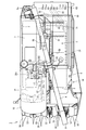
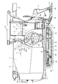
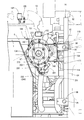
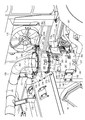
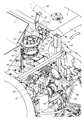
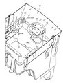
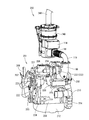
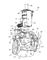
- FIG. 5 is an enlarged explanatory view of FIG. 4. It is a front perspective view of an engine and an exhaust gas purification device. It is a left view of an exhaust gas purification apparatus. FIG. It is upper surface side explanatory drawing of an exhaust-gas purification apparatus. It is explanatory drawing of the left side attachment part of an exhaust-gas purification apparatus. It is a cross-sectional explanatory view of the top perspective view of the driving cabin.
- FIGS. 1 to 3 the left side in the forward direction of the traveling machine body 1 is simply referred to as the left side, and the right side in the forward direction is also simply referred to as the right side.
- a traveling machine body 1 supported by a pair of left and right traveling crawlers 2 as traveling portions is provided.
- a 6-row mowing device 3 that takes in while harvesting cereals is mounted by a single-acting lifting hydraulic cylinder 4 so as to be movable up and down around the mowing pivot fulcrum shaft 4 a.
- the A threshing device 5 having a feed chain 6 and a grain tank 7 for storing the grains taken out from the threshing device 5 are mounted on the traveling machine body 1 side by side.
- the threshing device 5 is disposed on the left side of the traveling machine body 1, and the grain tank 7 is disposed on the right side of the traveling machine body 1.
- the reaping device 3, the threshing device 5, and the like correspond to the farm work unit provided in the traveling machine body 1.
- a grain discharge conveyor 8 is provided at the rear part of the traveling machine body 1 and can be swung via a vertical take-out conveyor 8 a, and the grains inside the grain tank 7 are transferred from the culling spout 9 of the grain discharge conveyor 8 to a truck bed or It is configured to be discharged into a container or the like.
- an operation cabin 10 is provided as a control unit.
- a cabin rotation fulcrum shaft 10a is provided in the lower front portion of the driving cabin 10, and the lower portion of the front surface of the operation cabin 10 is pivotally supported on the traveling machine body 1 via the cabin rotation fulcrum shaft 10a.
- the operation cabin 10 is movably installed, and the operation cabin 10 is configured to rotate forward about the cabin rotation fulcrum shaft 10a.
- the steering handle 11, the driving seat 12, the main transmission lever 15, the auxiliary transmission lever 16, the threshing clutch lever 17 for turning on and off the threshing clutch, and the cutting clutch lever for turning on and off the cutting clutch 18 are arranged.
- a common rail type diesel engine 201 (hereinafter simply referred to as an engine) as a power source is disposed in the traveling machine body 1 below the driver seat 12.
- the operation cabin 10 is provided with a step on which an operator gets on, a handle column provided with a steering handle 11, a lever column provided with the levers 15, 16, 17, 18 and the like.
- left and right track frames 21 are arranged on the lower surface side of the traveling machine body 1.
- the track frame 21 includes a drive sprocket 22 that transmits the power of the engine 201 to the traveling crawler 2, a tension roller 23 that maintains the tension of the traveling crawler 2, and a plurality of track rollers that hold the ground side of the traveling crawler 2 in a grounded state. 24 and an intermediate roller 25 that holds the non-grounded side of the traveling crawler 2 are provided.
- the driving sprocket 22 supports the front side of the traveling crawler 2
- the tension roller 23 supports the rear side of the traveling crawler 2
- the track roller 24 supports the grounding side of the traveling crawler 2
- the intermediate roller 25 supports the non-traveling crawler 2. Support the ground side.
- a clipper-type cutting blade device 52 that cuts a stock of uncut grain culm planted on a farm field is provided on a cutting frame 51 connected to a cutting rotation fulcrum shaft 4 a of the cutting device 3. Is provided. In front of the reaping frame 51, a stalk raising apparatus 53 for 6 stalks that raises an uncut cereal cultivated in the field is arranged. Between the culm pulling device 53 and the front end (feed start side) of the feed chain 6, a culm transporting device 54 that transports the chopped culm harvested by the cutting blade device 52 is arranged.
- a weeding body 55 corresponding to 6 strips for weeding the uncut cereal cedar is provided in front of the lower part of the cereal habit raising device 53.
- the reaping device 3 is configured to continuously shave the uncut cereal grains planted in the field.
- the threshing device 5 includes a handling cylinder 56 for threshing threshing, a rocking sorter 57 that sorts the cereals falling below the handling cylinder 56, and a tang fan 58.
- a processing cylinder 59 for reprocessing the threshing discharge taken out from the rear part of the cylinder 56 and a dust exhaust fan 60 for discharging dust at the rear part of the rocking sorter 57 are provided.
- the cereals conveyed by the culm conveying device 54 from the reaping device 3 are inherited by the feed chain 6, carried into the threshing device 5, and threshed by the handling cylinder 56.
- first conveyor 61 for taking out the grain (the first thing) sorted by the rocking sorter 57 and two branches such as a grain with branches and branches.
- a second conveyor 62 for taking out the articles is provided.
- the rocking sorter 57 is configured such that the cereal grains leaked from the receiving net 67 stretched below the handling cylinder 56 are rocked and sorted (specific gravity sorting) by the feed pan 68 and the chaff sheave 69. . Grains that fall from the swing sorter 57 are removed by the sorting air from the tang fan 58 and fall to the conveyor 61 first.
- the grain taken out first from the conveyor 61 is carried into the grain tank 7 via the cereal conveyor 63 and collected in the grain tank 7.
- the rocking sorter 57 is configured to drop a second thing such as a grain with a branch infarction from the chaff sheave 69 onto the second conveyor 62 by rocking sorting.
- a sorting fan 71 for wind-selecting the second object that falls below the chaff sheave 69 is provided.
- the dust and swarf in the grain are removed by the sorting air from the sorting fan 71 and dropped onto the second conveyor 62.
- the terminal end of the second conveyor 62 is connected to the upper surface side of the feed pan 68 via the reduction conveyor 66, and is configured to return the second product to the upper surface side of the swing sorting plate 67 and re-sort. Yes.
- a waste chain 64 and a waste cutter 65 are arranged on the rear end side (feed end side) of the feed chain 6.
- the waste passed through the feed chain 6 from the rear end side of the feed chain 6 (the straw from which the grain has been threshed) is discharged to the rear of the traveling machine body 1 in a long state, or the rear part of the threshing device 5
- the waste cutter 65 is discharged to the lower rear of the traveling machine body 1.
- the exhaust filter 202 includes a continuous regeneration type purification casing 240 for introducing exhaust gas of the engine 201.
- the purification casing 240 has an inlet side case 247 and an outlet side case 249. Inside the inlet side case 247 and the outlet side case 249, the diesel oxidation catalyst 243 such as platinum that generates nitrogen dioxide (NO 2 ) and the collected particulate matter (hereinafter referred to as PM) are continuously at a relatively low temperature.
- the diesel oxidation catalyst 243 such as platinum that generates nitrogen dioxide (NO 2 ) and the collected particulate matter (hereinafter referred to as PM) are continuously at a relatively low temperature.
- the soot filter 244 having a honeycomb structure to be oxidized and removed is arranged in series in the moving direction of the exhaust gas (from the lower side to the upper side in FIG. 7).
- the diesel oxidation catalyst 243 and the soot filter 244 in the inlet side case 247, outlet side case 249, carbon monoxide (CO) and hydrocarbon (HC) in the exhaust gas is comprised so that may be reduced.
- a purification inlet pipe 241 as an exhaust gas inlet pipe is welded and fixed to the inlet side case 247, and one end side of the purification outlet pipe 242 as an exhaust gas outlet pipe is fixed to the outlet side case 249. Fasten the bolts.
- One end side of the tail pipe 83 as an exhaust pipe is fitted in the other end side of the purification outlet pipe 242 in a loose fitting manner, and outside air is sucked from the loose fitting-like gap between the other end side of the purification outlet pipe 242 and one end side of the tail pipe 83.
- a tail pipe 83 is connected to the purification outlet pipe 242.
- the exhaust gas of the engine 201 is introduced into the purification casing 240 from the purification inlet pipe 241, the exhaust gas in the purification casing 240 is discharged from the purification outlet pipe 242 to the tail pipe 83, and the gas temperature is reduced in the tail pipe 83. After that, it is configured to be released outside the machine.
- the inlet side case 247 and the outlet side case 249 are detachably fastened by a plurality of thick plate-like flange bodies 271 and a plurality of bolts 272.
- nitrogen dioxide (NO 2 ) generated by the oxidation action of the diesel oxidation catalyst 243 is supplied into the soot filter 244 from one side end face (intake side end face).
- the PM contained in the exhaust gas of the engine 201 is collected by the soot filter 244 and continuously oxidized and removed by nitrogen dioxide (NO 2 ).
- the content of carbon monoxide (CO) and hydrocarbon (HC) in the exhaust gas of the engine 201 is reduced.
- an engine room frame 91 is erected on the traveling machine body 1, and the rear surface side of the engine 201 placed on the upper surface side of the traveling machine body 1 is surrounded by the engine room frame 91.
- the engine room frame 91 includes a left square pipe-shaped column body 92, a right square pipe-shaped column body 93, and a square pipe-shaped horizontal frame 94 that is integrally welded to both left and right column bodies 92, 93.
- a rubber pressure contact leg 95 is provided at the rear bottom of the driving cabin 10, and the pressure contact legs 95 at the bottom of the driving cabin 10 are brought into contact with the upper surfaces of the left and right cradles 96 of the horizontal frame 94 from the upper side.
- the rear part of the driving cabin 10 is supported on each of the cradles 96 so as to be able to contact and separate in the vertical direction.
- An engine 201 is installed inside an engine room 97 formed by the bottom surface side of the operating cabin 10 and the engine room frame 91.
- a pair of left and right purification case supports 111 are integrally fixed to the horizontal frame 94 by welding.
- the front support bracket 114 is integrally welded to the outer surface of the inlet side case 247 in the purification casing 240.
- the front support bracket 114 is disposed at the middle portion of the purification casing 240 in the vertical width direction (above the purification inlet pipe 241).
- the front part of the front support bracket 114 is fitted between the pair of left and right purification case supports 111 from the rear side, and screwed to the left and right sides of the pair of left and right purification case supports 111 and the front support bracket 114 from the left and right directions.
- the front support bracket 114 is detachably fastened to the purification case support 111 by the upper bolt 116a and the lower bolt 116b.
- the upper bolt 116 a is removably engaged with the engaging notch 111 a of the purification case support 111, and the lower bolt 116 b is attached to the position adjusting long hole 111 b of the purification case support 111.
- the upper bolt 116 a is temporarily fixed to the front support bracket 114, the exhaust filter 202 is brought close to the attachment position of the purification case support 111, and the engagement notch 111 a of the purification case support 111 is formed.
- the upper bolt 116a is engaged, and the purification casing 240 is temporarily supported by the purification case support 111.
- the lower bolt 116b is passed through the position adjusting long hole 111b of the purification case support 111, the lower bolt 116b is fastened to the front support bracket 114, and the upper bolt 116a is also fastened to the front support bracket 114.
- the front support bracket 114 is detachably fixed to the purification case support 111, and the exhaust filter 202 is mounted on the back side of the engine room 97 via the horizontal frame 94.
- a top plate body 114a and a bottom plate body 114b are welded and fixed to the upper end side and the lower end side of the U-shaped front support bracket 114 in plan view, so that the front support bracket 114 has a rectangular box-like high-rigidity structure. Is formed.
- the engine room 97 is formed on the lower side of the driving cabin 10, the driving cabin 10 is movably installed toward the upper front side (outer side of the aircraft) of the traveling machine body 1, and the cradle 96 that supports the driving cabin 10.
- the purification case support 111 that supports the purification casing 240 are arranged in the same part (the horizontal frame 94) of the engine room frame 91 so that the operation cabin 10 can be brought into contact with and separated from the purification casing 240. .
- a side support bracket 141 is integrally welded to the left outer peripheral surface of the inlet side case 247 in the purification casing 240.
- the front support bracket 114 and the side support bracket 141 are arranged radially (in the cross direction) on the same circumference on the outer surface of the entrance side case 247.
- a bolt 143 is fastened to the side support bracket 141 so that the position of one end of the assembly adjustment plate 142 can be adjusted, and the other end of the assembly adjustment plate 142 is fastened to the right side surface of the machine frame 144 of the threshing device 5.
- the side support bracket 141 and the machine frame 144 are connected and fixed so that the position can be adjusted via the assembly adjustment plate 142.
- the side surface of the purification case support 111 and the right side of the threshing device 5 are detachably connected via a side surface support bracket 141.
- the front surface of the inlet side case 247 is fastened and fixed to the engine room 97 side (horizontal frame 94), while the left side surface of the inlet side case 247 is fastened and fixed to the threshing device 5 side (machine casing frame 144).
- the intermediate portion of the purification casing 240 is fixed to the engine room frame 91 through the inlet side case 247 in a vertically placed posture. Further, of the exhaust gas supply side at the lower end side of the purification casing 240, the purification inlet pipe 241 is provided in a forward posture on the front side surface of the purification casing 240, and the purification inlet pipe 241 extends toward the upper surface side of the engine 201 (front of the machine body).
- An exhaust manifold 207 and a turbocharger 232 are arranged on the front side upper portion of the engine 201 mounted on the traveling machine body 1 with the crankshaft 203 directed in the left-right direction.
- One end side of the exhaust connection pipe 119 is connected to the purification inlet pipe 241 via a bendable bellows-like exhaust introduction pipe 98, while the other end side of the exhaust connection pipe 119 is connected to the exhaust outlet pipe 99 of the supercharger 118.
- a purification casing 240 is connected to the exhaust manifold 207 via a supercharger 232 and an exhaust connection pipe 119.
- a pipe inlet side support 151 and a pipe outlet side support 152 which are respectively fixed to the exhaust inlet side and the exhaust outlet side of the tail pipe 83 are provided.
- the left end portion of the thick plate-like flange body 273 on the upper surface of the purification casing 240 is projected in the direction of the threshing device 5, and one end side of the exhaust support base 153 is fastened to the left end portion of the thick plate-like flange body 273.
- the other end side of the exhaust support base 153 protrudes from the left end portion of the flange body 273 toward the threshing device 5.
- the lower end side of the inlet side bracket 154 is fastened to the other end side of the exhaust support base 153, the inlet side bracket 154 is erected on the exhaust support base 153, and the lower end side of the pipe inlet side support body 151 is positioned on the upper end side of the inlet side bracket 154. Conclude.
- outlet side bracket 155 is erected on the right side of the upper surface of the threshing device 5, and the lower end side of the pipe outlet side support 152 is fastened to the upper end side of the outlet side bracket 155.
- a tail pipe 83 is provided across the upper surface of the purification casing 240 and the upper surface of the threshing device 5 via the pipe inlet side support 151 and the pipe outlet side support 152 that are erected on the upper surface sides of the threshing device 5 and the purification casing 240. Extend.
- a tail pipe 83 is supported on each upper surface side of the threshing device 5 and the purification casing 240.
- the inner diameter of the tail pipe 83 is formed larger than the outer diameter of the purification outlet pipe 242, and a gap is formed at the connecting portion between the purification outlet pipe 242 on the small diameter side and the tail pipe 83 on the large diameter side.
- the exhaust gas moving from the purification outlet pipe 242 into the tail pipe 83 is mixed with the outside air sucked into the tail pipe 83 through the gap to reduce the temperature of the exhaust gas discharged from the tail pipe 83. It is configured.
- an umbrella-shaped upper surface cover body 156 that covers the upper surface side of the purification casing 240 is provided.
- Cover support brackets 157 are radially fixed to the outer peripheral surface of tail pipe 83 on the exhaust gas inlet side (connection portion with purification outlet pipe 242).
- a top cover body 156 is detachably fastened to the cover support bracket 157 with a bolt 158.
- the upper surface cover body 156 is configured to prevent dust and soot from accumulating on the upper surface of the purification casing 240.
- the outlet side cover body 265 is detachably fastened and fixed to the outlet side case 249 of the purification casing 240 via a plurality of thick plate-like flange bodies 273.
- An outlet pipe flange body 87 is welded and fixed to the lower end side of the purification outlet pipe 242, and the purification outlet pipe 242 is supported on the outlet side case 249 via the outlet side cover body 265.
- a pair of suspended engagement holes 134 are provided on the upper end side of the outer surface of the purification casing 240 (exhaust filter 202).
- the pair of hanging engagement holes 134 are formed integrally with the front end and the rear end of the upper end flange body 86 by projecting the front end edge and the rear end edge of the thick plate upper end flange body 86 in the radial direction. ing.
- a hook of a cargo handling suspension device such as a chain block or a hoist is locked to the suspension engagement hole 134, and the suspension engagement hole 134 (upper end)
- the purification casing 240 is suspended via a flange body 86), and the heavy purification casing 240 is transported and moved. Operations such as assembly or removal of the purification casing 240 can be easily performed, and the detachability workability of the exhaust filter 202 can be improved.
- the sensor bracket 283 is bolted to the thick plate-like flange body 273 projecting radially in the right direction of the outlet side case 249, and the sensor bracket 283 is disposed on the right side portion on the upper end side of the purification casing 240.
- a differential pressure sensor 281 integrally provided with an electrical wiring connector is attached to a flat upper surface of a sensor bracket 283 projecting laterally from the purification casing 240.
- the differential pressure sensor 281 is connected to one end sides of an upstream sensor pipe 288 and a downstream sensor pipe 289, respectively.
- the other end sides of the sensor pipes 288 and 289 on the upstream and downstream sides are respectively connected to the pressure boss bodies 292 on the upstream and downstream sides arranged in the purification casing 240 so as to sandwich the soot filter 244 in the purification casing 240.
- a difference between the exhaust gas pressure on the inflow side of the soot filter 244 and the exhaust gas pressure on the outflow side of the soot filter 244 is detected via the differential pressure sensor 281. Since the residual amount of particulate matter in the exhaust gas collected by the soot filter 244 is proportional to the differential pressure of the exhaust gas, the difference occurs when the amount of particulate matter remaining in the soot filter 244 increases more than a predetermined amount. Based on the detection result of the pressure sensor 281, regeneration control for reducing the amount of particulate matter in the soot filter 244 (for example, control for increasing the exhaust temperature) is executed. For example, when the residual amount of the particulate matter further increases beyond the recyclable range, the cleaning casing 240 is detached and disassembled, the soot filter 244 is cleaned, and the maintenance work for artificially removing the particulate matter is performed. .
- an electrical wiring connector is integrally provided on the outer case portion of the differential pressure sensor 281 for electrical wiring, and a DPF temperature sensor 282 for detecting the exhaust gas temperature in the diesel oxidation catalyst 243 is provided.
- the electrical wiring connector 294 of the DPF temperature sensor 282 is fixed to the sensor bracket 283.
- a differential pressure sensor 281 and an electric wiring connector 294 of the DPF temperature sensor 282 are arranged on the upper part of the purification casing 240 via a sensor bracket 283.
- Each connector 294 is supported in a posture in which the connection directions of the electrical wiring connector of the differential pressure sensor 281 and the electrical wiring connector 294 of the DPF temperature sensor 282 are oriented in the same direction.
- the upper portion of the purification casing 240 is disposed so as to face the air discharge portion of the air conditioning fan 115 installed on the back surface of the operation cabin 10. Therefore, the wiring of the differential pressure sensor 281 or each connector 294 can be cooled by the exhaust of the air conditioning fan 115. The exhaust heat on the purification casing 240 side can prevent them from burning and improve their durability.
- the rear part of the grain tank 7 is supported by the vertical take-out conveyor 8a that supports the grain discharge conveyor 8, and the front side of the grain tank 7 is arranged around the vertical take-out conveyor 8a.
- the grain tank 7 is provided so as to be horizontally rotated and move toward the outside of the machine.
- a plurality of cover support bases 136 are welded and fixed to the rear surface side of the purification casing 240 facing the grain tank 7, and a rear cover body 137 is detachably fastened to each cover support base 136.
- the purification casing 240 is disposed between the engine room 97 (engine room frame 91) and the grain tank 7, and the rear cover body 137 is disposed between the grain tank 7 and the purification casing 240.
- the rear cover body 137 prevents the operator from coming into contact with the purification casing 240 when the grain tank 7 is moved toward the outside of the machine and the rear side of the engine room 97 is opened to perform maintenance work. It is configured to do.
- the driving cabin 10 includes the steering handle 11 for changing the traveling (turning) direction of the traveling machine body 1 and the driving seat 12 on which the operator is seated.
- a main transmission lever 15 that performs a speed change operation of the traveling machine body 1 is arranged on a side column 160 arranged on the left side of the driver seat 12.
- the auxiliary transmission lever 16, the threshing clutch lever 17 and the harvesting clutch lever 18 are also arranged in the side column 160.
- a display device 161 capable of displaying various information such as characters, symbols, and images is disposed inside the steering wheel 165 of the steering handle 11.
- the display device 161 includes a liquid crystal monitor 162 and an outer case 163 that accommodates the liquid crystal monitor 162.
- the display device 161 is fixed to the front column 166 side that supports the steering handle 11 and is not connected to the steering handle 11. For this reason, even if the steering handle 11 is turned, the display device 161 does not move, and the screen is always easy to see from the operator.
- a display changeover switch 164 which is an example of a display changeover member, is provided on the outer peripheral side of the liquid crystal monitor 162 in the outer case 163.
- the display changeover switch 164 is a non-locking type push switch that generates one ON pulse signal when pressed once.
- the liquid crystal monitor 162 and the display changeover switch 164 are electrically connected to a display ECU 351 (details will be described later) as a separate ECU.
- An engine 201 as a prime mover mounted on a farm vehicle includes an exhaust filter 202 (diesel particulate filter) which is a continuously regenerative exhaust gas purification device.
- the exhaust filter 202 removes PM in the exhaust gas exhausted from the engine 201 and reduces carbon monoxide (CO) and hydrocarbons (HC) in the exhaust gas.
- the engine 201 includes a cylinder block 204 that incorporates a crankshaft 203 that is an engine output shaft and a piston (not shown).
- a cylinder head 205 is mounted on the cylinder block 204.
- An intake manifold 206 is disposed on the rear side surface of the cylinder head 205, and an exhaust manifold 207 is disposed on the front side surface of the cylinder head 205.
- the upper surface side of the cylinder head 205 is covered with a head cover 208.
- the left and right ends of the crankshaft 203 protrude from the left and right sides of the cylinder block 204.
- a cooling fan 209 is provided on the right side of the engine 201. Rotational power is transmitted from the left end side of the crankshaft 203 to the cooling fan 209 via the cooling fan V-belt 222.
- a flywheel housing 210 is provided on the rear side of the engine 201.
- a flywheel 211 is accommodated in the flywheel housing 210 while being supported on the rear end side of the crankshaft 203.
- the rotational power of the engine 201 is transmitted from the crankshaft 203 to the operating part of the work machine via the flywheel 211.
- An oil pan 212 that stores lubricating oil is disposed on the lower surface of the cylinder block 204. Lubricating oil in the oil pan 212 is supplied to each lubricating portion of the engine 201 through an oil filter 213 and the like disposed on the rear side of the cylinder block 204, and then returns to the oil pan 212.
- a fuel supply pump 214 is provided on the rear side of the cylinder block 204 above the oil filter 213 (below the intake manifold 206). Further, the engine 201 includes an injector 215 for four cylinders having an electromagnetic opening / closing control type fuel injection valve 219 (see FIG. 17). A common rail device 220 that injects fuel into each cylinder of the engine 201 in a single combustion cycle is provided below the intake manifold 206 on the rear side of the cylinder block 204. Each injector 215 is connected to a fuel tank 218 mounted on the work machine via a fuel supply pump 214, a common rail device 220, and a fuel filter 217.
- the fuel in the fuel tank 218 is pumped from the fuel supply pump 214 to the common rail device 220 via the fuel filter 217.
- the fuel injection valve 219 of each injector 215 By controlling the fuel injection valve 219 of each injector 215 to open and close, the high-pressure fuel stored in the common rail device 220 is injected from each injector 215 to each cylinder of the engine 201.
- the cooling water pump 221 for cooling water lubrication is disposed coaxially with the fan shaft of the cooling fan 209 on the left side of the cylinder block 204.
- the cooling water pump 221 is driven together with the cooling fan 209 via the cooling fan V-belt 222 by the rotational power of the crankshaft 203.
- Cooling water in a radiator (not shown) mounted on the work machine is supplied to the cylinder block 204 and the cylinder head 205 by driving the cooling water pump 221 to cool the engine 201. Cooling water that has contributed to cooling of the engine 201 is returned to the radiator.
- An alternator 223 is arranged on the left side of the cooling water pump 221.
- the engine leg mounting portions 224 are provided on the front and rear sides of the cylinder block 204, respectively. Each engine leg mounting portion 224 is bolted to an engine leg body (not shown) having anti-vibration rubber.
- the engine 201 is supported in an anti-vibration manner by a work machine (specifically, an engine mounting chassis) through each engine leg.
- the inlet portion of the intake manifold 206 is connected to an air cleaner (not shown) via an EGR device 226 (exhaust gas recirculation device).
- the fresh air (external air) sucked into the air cleaner is dust-removed and purified by the air cleaner, and then sent to the intake manifold 206 via the EGR device 226 and supplied to each cylinder of the engine 201.
- the EGR device 226 mixes a part of the exhaust gas of the engine 201 (EGR gas from the exhaust manifold 207) and fresh air (external air from the air cleaner) and supplies the mixed air to the intake manifold 206, and the air cleaner
- An intake throttle member 228 for communicating the EGR main body case 227, a recirculation exhaust gas pipe 230 connected to the exhaust manifold 207 via an EGR cooler 229, and an EGR valve member for communicating the EGR main body case 227 with the recirculation exhaust gas pipe 230 231.
- An intake throttle member 228 is connected to the intake manifold 206 via an EGR main body case 227.
- the intake throttle member 228 is bolted to one end of the EGR main body case 227 in the longitudinal direction.
- the left and right inwardly open end portions of the EGR main body case 227 are bolted to the inlet portion of the intake manifold 206.
- the outlet side of the recirculation exhaust gas pipe 230 is connected to the EGR main body case 227 via an EGR valve member 231.
- the inlet side of the recirculated exhaust gas pipe 230 is connected to the lower surface side of the exhaust manifold 207 via an EGR cooler 229.
- fresh air is supplied from the air cleaner into the EGR main body case 227 via the intake throttle member 228, while EGR is supplied from the exhaust manifold 207 into the EGR main body case 227 via the EGR valve member 231.
- Gas (a part of the exhaust gas discharged from the exhaust manifold 207) is supplied.
- the mixed gas in the EGR main body case 227 is supplied to the intake manifold 206.
- a turbocharger 232 is disposed on the right side of the cylinder head 205 and above the exhaust manifold 207.
- the turbocharger 232 includes a turbine case 233 with a built-in turbine wheel (not shown) and a compressor case 234 with a blower foil (not shown).
- the exhaust inlet side of the turbine case 233 is connected to the outlet portion of the exhaust manifold 207.
- the exhaust outlet side of the turbine case 233 is connected to a tail pipe (not shown) via an exhaust filter 202. Exhaust gas discharged from each cylinder of the engine 201 to the exhaust manifold 207 is discharged from the tail pipe to the outside through the turbine case 233 of the turbocharger 232, the exhaust filter 202, and the like.
- the intake inlet side of the compressor case 234 is connected to an air cleaner via an intake pipe.
- An intake outlet side of the compressor case 234 is connected to an intake throttle member 228 via a supercharging pipe.
- the fresh air removed by the air cleaner is sent from the compressor case 234 to the intake manifold 206 via the intake throttle member 228 and the EGR main body case 227 and supplied to each cylinder of the engine 201.
- the intake pipe is connected to a breather chamber in the head cover 208 via a blow-by gas return pipe.
- the blow-by gas from which the lubricating oil is separated and removed in the breather chamber is returned to the intake pipe through the blow-by gas return pipe, is returned to the intake manifold 206, and is supplied again to each cylinder of the engine 201.
- each injector 215 includes an electromagnetic switching control type fuel injection valve 219.
- the common rail device 220 includes a cylindrical common rail 216 (pressure accumulation chamber).
- the suction side of the fuel supply pump 214 is connected to a fuel tank 218 via a fuel filter 217 and a low pressure pipe 261.
- the fuel in the fuel tank 218 is sucked into the fuel supply pump 216 via the fuel filter 217 and the low pressure pipe 261.
- a common rail 216 is connected to the discharge side of the fuel supply pump 216 via a high-pressure pipe 262.
- Four rails of injectors 215 are connected to the common rail 216 via four fuel injection pipes 263.
- a fuel supply pump 214 is connected to the fuel tank 218 via a fuel return pipe 264.
- One end of the common rail return pipe 267 is connected to the end of the common rail 216 in the longitudinal direction via a return pipe connector 266 that limits the fuel pressure in the common rail 216.
- the other end side of the common rail return pipe 267 is connected to the fuel tank 218 via the fuel return pipe 264 (joins the fuel return pipe 264).
- the surplus fuel in the fuel supply pump 214 and the surplus fuel in the common rail 216 are recovered in the fuel tank 218 via the fuel return pipe 264 and the common rail return pipe 267.
- the fuel in the fuel tank 218 is pumped to the common rail device 220 by the fuel supply pump 216 and stored in the common rail 216 as high-pressure fuel.
- the opening and closing (electronic control) of each fuel injection valve 219 the high pressure fuel in the common rail 216 is controlled with high accuracy in injection pressure, injection timing, and injection period (injection amount).
- 115 is injected into each cylinder of engine 201. Therefore, nitrogen oxide (NOx) discharged from the engine 201 can be reduced, and noise vibration of the engine 201 can be reduced.
- NOx nitrogen oxide
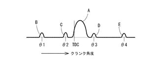
- the common rail device 220 is configured to execute the main injection A near the top dead center (TDC).
- TDC top dead center
- the common rail device 220 performs a small amount of pilot injection B for the purpose of reducing NOx and noise at a crank angle ⁇ 1 of about 60 ° before the top dead center
- Pre-injection C is executed for the purpose of reducing noise immediately before the crank angle ⁇ 2
- after-injection is performed for the purpose of reducing PM and promoting exhaust gas purification at the crank angles ⁇ 3 and ⁇ 4 after top dead center.
- D and post-injection E are executed.
- Pilot injection B is a fuel that promotes mixing of fuel and air by being injected at a time when the main injection A is greatly advanced.
- the pre-injection C is performed prior to the main injection A to shorten the ignition timing delay in the main injection A.
- After-injection D is performed with a slight delay with respect to main injection A, thereby activating diffusion combustion and raising the temperature of exhaust gas from engine 201 (reburning PM).
- the post-injection E is supplied to the exhaust filter 202 as unburned fuel without contributing to the actual combustion process by being injected at a timing that is largely retarded with respect to the main injection A.
- the unburned fuel supplied to the exhaust filter 202 reacts on the diesel oxidation catalyst 243, and the exhaust gas temperature in the exhaust filter 202 rises due to the reaction heat.
- the level of the peaks in the graph in FIG. 18 roughly represents the difference in fuel injection amount at each injection stage A to E.
- an engine ECU 311 for operating the fuel injection valve 219 of each cylinder in the engine 201 and a display ECU 351 that is a separate ECU configured separately from the engine ECU are provided.
- the engine ECU 311 and the display ECU 351 include a CPU that executes various arithmetic processes and controls, a ROM that stores various data fixedly in advance, a ROM that stores a control program and various data in a rewritable manner, It has a RAM for temporarily storing a control program and various data, a timer for measuring time, an input / output interface, and the like.
- ECU 311 and display ECU 351 are electrically connected to each other via CAN communication bus 350.
- the engine ECU 311 is disposed at or near the engine 201
- the display ECU 351 is disposed within the outer case 163 of the display device 161.
- the engine ECU 311 is connected to the battery 332 via a key switch 331 for applying power.
- the key switch 331 is a rotary switch that can be rotated to three terminal positions including a cutting position, an entering position, and a starter position by a predetermined key inserted into the keyhole.
- the key switch 331 is provided on the front column 166 that supports the steering handle 11.
- the input position (terminal) of the key switch 331 is connected to the input side of the engine ECU 311.
- At least the rail pressure sensor 312 for detecting the fuel pressure in the common rail 216, the electromagnetic clutch 313 for rotating or stopping the fuel pump 214, and the rotational speed of the engine 201 (camshaft position of the crankshaft 203) are provided on the input side of the engine ECU 311.
- At least an electromagnetic solenoid of each fuel injection valve 219 for four cylinders is connected to the output side of the engine ECU 311. That is, the high-pressure fuel stored in the common rail 216 is injected from the fuel injection valve 219 in a plurality of times during one stroke while controlling the fuel injection pressure, the injection timing, the injection period, and the like, so that nitrogen oxide (NOx ), And complete combustion with reduced generation of soot, carbon dioxide (CO 2 ) and the like is performed to improve fuel efficiency.
- Also connected to the output side of the engine ECU 311 are an intake throttle member 228 for adjusting the intake pressure (intake amount) of the engine 201, an EGR valve member 231 for adjusting the supply amount of EGR gas to the intake manifold 206, and the like. ing.
- a display changeover switch 164 is connected.
- the liquid crystal monitor 162 of the display device 161 As a warning lamp blinking in relation to the exhaust filter 202 regeneration operation, and the exhaust filter 202 regeneration operation, etc.
- the alarm buzzer 330 is connected. Data relating to blinking of the regeneration lamp 328 and sounding of the alarm buzzer 330 is stored in advance in the ROM of the display ECU 351.
- the regeneration switch 322 is of a momentary operation type. That is, the regeneration switch 322 is a non-locking type push switch that generates one ON pulse signal when pressed once.
- the pressing time of the regeneration switch 322 by the operator is adopted as one of criteria for determining whether or not each regeneration control after the reset regeneration control (details will be described later) can be executed.
- a regeneration lamp 328 is built in the regeneration switch 322 of the embodiment. That is, the regeneration switch 322 is configured as a switch with a regeneration lamp 328.
- the regeneration switch 322 is disposed in the driving cabin 10 on the left side of the steering handle 11 and in front of the main transmission lever 15. That is, the regeneration switch 322 is disposed in the vicinity where the left / right direction of the steering handle 11 intersects the front / rear direction of the main transmission lever 15.
- the safety switch 324 is a parking brake sensor that detects an on / off state of the parking brake pedal (not shown) that maintains the left and right traveling crawlers 2 that are traveling units in a braking state (not shown).
- the ROM of the engine ECU 311 stores in advance an output characteristic map M (see FIG. 19) indicating the relationship between the rotational speed N of the engine 201 and the torque T (load).
- the ROM of the engine ECU 311 stores an exhaust gas flow rate map for converting the exhaust gas flow rate from the relationship between the rotational speed N of the engine 201 and the fuel injection amount, and the rotational speed N of the engine 201 and the fuel.
- a PM emission amount map for converting the PM emission amount of the engine 201 from the relationship with the injection amount is also stored in advance.
- Each map such as the output characteristic map M is obtained by experiments or the like. In the output characteristic map M shown in FIG.
- the rotational speed N is taken on the horizontal axis and the torque T is taken on the vertical axis.
- the output characteristic map M is a region surrounded by a solid line Tmx drawn upwardly.
- a solid line Tmx is a maximum torque line representing the maximum torque for each rotational speed N.
- the output characteristic maps M stored in the engine ECU 311 are all the same (common).
- the output characteristic map M is divided into upper and lower parts by boundary lines BL1 and BL2 representing the relationship between the rotational speed N and the torque T at a predetermined exhaust gas temperature.
- the region above the first boundary line BL1 is a self-regenerating region in which PM deposited on the soot filter 244 can be oxidized and removed only by normal operation of the engine 201 (the oxidation action of the diesel oxidation catalyst 243 works).
- PM is deposited on the soot filter 244 without being oxidized and removed only by the normal operation of the engine 201, but the assist regeneration control and reset regeneration control described later.
- This is a reproducible region that the exhaust filter 202 regenerates by execution.
- the region below the second boundary line BL2 is a non-reproducible region where the exhaust filter 202 is not regenerated in the assist regeneration control or the reset regeneration control.
- the exhaust gas temperature of the engine 201 in the non-renewable region is too low, the exhaust gas temperature does not rise to the regeneration boundary temperature even if the assist regeneration control or the reset regeneration control is executed from this state. That is, if the relationship between the rotational speed N of the engine 201 and the torque T is in the non-recoverable region, the exhaust filter 202 is not regenerated by the assist regeneration control or the reset regeneration control (the particulate matter collecting ability of the soot filter 244 is not recovered). ).
- the exhaust gas temperature on the first boundary line BL1 is a self-regenerating regeneration boundary temperature (about 300 ° C.).
- the engine ECU 311 basically calculates the torque of the engine 201 from the rotation speed detected by the engine rotation sensor 314 and the throttle position detected by the throttle position sensor 316, and calculates the target fuel injection amount using the torque and output characteristics. Then, fuel injection control for operating the common rail device 220 is executed based on the calculation result.
- the fuel injection amount of the common rail device 220 is mainly adjusted by adjusting the valve opening period of each fuel injection valve 219 and changing the injection period to each injector 215.
- normal operation control self-regeneration control
- the assist regeneration control for automatically increasing the exhaust gas temperature by utilizing the load increase of the engine 201
- the reset regeneration control for increasing the exhaust gas temperature by using the post injection E, and the high idle of the post injection E and the engine 201.
- parking regeneration control (which may be called emergency regeneration control) that increases the exhaust gas temperature in combination with the rotation speed
- recovery regeneration control that can be executed when parking regeneration control fails.
- Normal operation control is a control format when driving on the road or during agricultural work (harvesting work).
- the relationship between the rotational speed N and the torque T in the engine 201 is in the self-regeneration region of the output characteristic map M, and the engine 201 is adjusted to such an extent that the PM oxidation amount in the exhaust filter 202 exceeds the PM collection amount.
- the exhaust gas is hot.
- the exhaust filter 202 is regenerated by adjusting the opening degree of the intake throttle member 228 and after-injection D. That is, in the assist regeneration control, the intake air amount to the engine 201 is limited by closing the EGR valve member 231 and closing (squeezing) the intake throttle member 228 to a predetermined opening. Then, since the engine 201 load increases, the fuel injection amount of the common rail device 220 increases to maintain the set rotational speed, and the exhaust gas temperature of the engine 201 increases. In accordance with this, the diffusion combustion is activated by the after-injection D that is injected with a slight delay with respect to the main injection A, and the exhaust gas temperature of the engine 201 is raised. As a result, PM in the exhaust filter 202 is burned and removed. In any of the regeneration controls described below, the EGR valve member 231 is closed.
- the reset regeneration control is performed when the assist regeneration control fails (when the clogged state of the exhaust filter 202 does not improve and PM remains), or when the accumulated drive time TI of the engine 201 is equal to or longer than a set time TI1 (for example, about 100 hours). It is done when it becomes.
- the exhaust filter 202 is regenerated by performing post injection E in addition to the assist regeneration control. That is, in the reset regeneration control, in addition to the adjustment of the opening degree of the intake throttle member 228 and the after-injection D, the unburned fuel is directly supplied into the exhaust filter 202 by the post-injection E, and the unburned fuel is supplied by the diesel oxidation catalyst 243. By burning, the exhaust gas temperature in the exhaust filter 202 is raised (about 560 ° C.). As a result, the PM in the exhaust filter 202 is forcibly burned and removed.
- Parking regeneration control is performed when reset regeneration control fails (when the clogged state of the exhaust filter 202 does not improve and PM remains).
- the exhaust gas temperature of the engine 201 is increased by maintaining the rotational speed N of the engine 201 at a high idle rotational speed (maximum rotational speed, for example, 2200 rpm).
- the exhaust gas temperature is raised by the post injection E (about 600 ° C.).
- the PM in the exhaust filter 202 is forcibly burned and removed under better conditions than the reset regeneration control.
- the intake throttle member 228 in the parking regeneration control is not throttled but is completely closed.
- the after injection D in the parking regeneration control is performed by retarding (retarding) the assist regeneration control and the reset regeneration control.
- the output of the engine 201 is limited to a maximum output during parking that is lower than the maximum output (for example, about 80% of the maximum output).
- the rotational speed N of the engine 201 is maintained at a high idle rotational speed, the fuel injection amount of the common rail device 220 is adjusted so that the torque T is suppressed and the maximum output during parking is achieved.
- the recovery regeneration control is performed when the parking regeneration control fails (when the clogged state of the exhaust filter 202 is not improved and PM is excessively deposited).
- the recovery reproduction control of the embodiment is executed in two stages of recovery first reproduction control and recovery second reproduction control.
- the recovery first regeneration control gradually regenerates the exhaust filter 202 by gradually burning and removing the PM in the exhaust filter 202 in a situation where there is a risk of runaway combustion of the excessively accumulated PM.
- the exhaust filter 202 is promptly regenerated in a situation where there is no risk of runaway combustion.
- the overall recovery regeneration control is performed basically in the same manner as in the parking regeneration control mode.
- the fuel injection amount in the post injection E for example, the exhaust gas temperature in the exhaust filter 202 is lower than the parking regeneration control at a temperature TP3 (for example, 450 ° C. or less) and takes longer time (for example, 3 hours) than the parking regeneration control.
- the PM in 202 is gradually burned and removed.
- the output of the engine 201 is limited to the maximum output during recovery that is lower than the maximum output during parking (for example, about 80% of the maximum output).
- the fuel injection amount of the common rail device 220 is adjusted so that not only the torque T of the engine 201 but also the rotational speed N is suppressed and the maximum output during recovery is obtained.
- the exhaust gas temperature in the exhaust filter 202 is higher than that in the recovery first regeneration control by closing the intake throttle member 228, after-injection D, post-injection E, and the high idle rotation speed of the engine 201.
- the exhaust filter 202 is quickly regenerated so as to be TP4 (for example, 550 ° C. or higher). That is, the aspect of the recovery second regeneration control is the same as the aspect of the parking regeneration control.
- the power of the engine 201 is transmitted to the traveling crawler 2 as a traveling unit, the reaping device 3 and the threshing device 5 as an agricultural working unit, etc. It is possible to perform traveling and farm work (the engine 201 can be driven in normal operation).
- the engine 201 In the parking regeneration control and the recovery regeneration control, the engine 201 is driven exclusively for PM combustion removal, and the traveling crawler 2, the reaping device 3, the threshing device 5 and the like are not driven by the power of the engine 201.
- the exhaust filter 202 regeneration control first, if the key switch 331 is on (S101: YES), detection by the engine rotation sensor 314, the coolant temperature sensor 319, the differential pressure sensor 281 and the DPF temperature sensor 282 is detected. The value, the opening degree of the intake throttle member 228 and the EGR valve member 231 and the fuel injection amount by the common rail device 220 are read (S102). Next, if the cumulative driving time TI after executing the assist regeneration control, reset regeneration control or non-work regeneration control in the past is less than the set time TI1 (for example, 50 hours) (S103: NO), the exhaust filter 202 The amount of PM deposition is estimated (S104).
- the PM accumulation amount estimation is based on the P method based on the detection value of the differential pressure sensor 281 and the exhaust gas flow rate map, the C method based on the detection value of the engine rotation sensor 314, the fuel injection amount, the PM emission amount map, and the exhaust gas flow rate map. Using the law. If the PM accumulation amount is not less than a prescribed amount Ma (for example, 8 g / l) (S105: YES), assist regeneration control is executed (S106).
- a prescribed amount Ma for example, 8 g / l
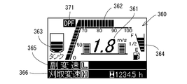
- the speed monitor 361 indicating the traveling speed (vehicle speed) of the traveling body 1, the load graph 362 indicating the engine load, the grain, as the normal report 360 on the liquid crystal monitor 162.
- the tank monitor 363 that informs the amount of stored grain in the tank 7, the fuel meter 364 that informs the remaining amount of fuel, the sub-transmission monitor 365 that informs the setting state of the sub-transmission lever 16, and the drive speed setting state in the reaping device 3
- a cutting shift monitor 366 and the like for notification are displayed (see FIG. 23).
- reproduction request information that prompts the execution (details will be described later) and other reproduction information are not displayed on the liquid crystal monitor 162. Further, the regeneration lamp 328 and the alarm buzzer 330 are not operated.
- the assist regeneration control is terminated and the normal operation control is resumed. If it is within the predetermined time TI3 from the start of the assist regeneration control (S107: NO), the PM accumulation in the exhaust filter 202 is based on the detected value of the engine rotation sensor 314, the fuel injection amount, the PM emission amount map, and the exhaust gas flow rate map. The amount is estimated (S108). If the PM accumulation amount is less than a prescribed amount Ma (for example, 6 g / l) (S109: YES), the assist regeneration control is terminated and the normal operation control is resumed.
- a prescribed amount Ma for example, 6 g / l
- step S103 when the cumulative drive time TI is equal to or longer than the set time TI1 (S103: YES), the process proceeds to step S201 which is a reset standby mode.
- the reproduction lamp 328 blinks at a low speed (for example, 0.5 Hz), and the alarm buzzer 330 sounds intermittently at a low speed (for example, 0.5 Hz).
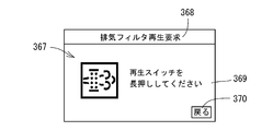
- the screen display of the liquid crystal monitor 162 is changed from the normal information 360 to reset reproduction request information 367 (see FIG. 24) that prompts execution of reset reproduction control. On the screen of the reset regeneration request information 367 shown in FIG.
- the operation instruction indicator 370 means that the screen display of the liquid crystal monitor 162 returns from the reset reproduction request information 367 to the normal information 360 by turning on the display changeover switch 164.
- the display changeover switch 164 is turned on while the reset reproduction request information 367 is displayed on the screen of the liquid crystal monitor 162 without turning on the reproduction switch 322, the screen display of the liquid crystal monitor 162 is changed to the normal information 360. Transitions to the reset reproduction request information 367 alternately at a predetermined timing (for example, every 2 seconds).
- the reset regeneration control is required, the operator can confirm both the normal information 360 and the reset regeneration request information 367, and considers that there is no problem in the operation of the combine during traveling on the road or farming.
- the regeneration switch 322 When the regeneration switch 322 is turned on for a predetermined time (for example, 3 seconds), if the exhaust gas temperature TP in the exhaust filter 202 is equal to or higher than TP1 (for example, 250 ° C.) (S201: YES), reset regeneration control is executed (S202). ). At this stage, the regeneration lamp 328 is turned on, and the alarm buzzer 330 is turned off. Then, the screen display of the liquid crystal monitor 162 is changed from the reset reproduction request information 367 to the normal information 360 (see FIG. 25).
- TP1 for example, 250 ° C.
- a notification mark 371 such as a symbol for notifying that the reset regeneration control is being executed or a symbol mark or the like is displayed on the screen of the normal information 360 during the reset reproduction control shown in FIG. indicate. For this reason, even on the screen showing the normal information 360, the operator can easily recognize that the reset regeneration control is being executed, and can call the operator's attention.
- the PM accumulation amount in the exhaust filter 202 is estimated (S203), and the PM accumulation amount is the prescribed amount Mr ( For example, if a predetermined time TI5 (for example, 1 hour) elapses in a state of less than 6 g / l) (S204: YES), the process returns from the reset standby mode to the normal operation control. If the predetermined time TI6 (for example, 3 hours) has elapsed with step S204 set to NO (S205: YES), there is a concern about the possibility of PM overdepositing, so the step is a parking standby mode before parking regeneration control. The process proceeds to S301.
- a predetermined time TI5 for example, 1 hour
- TI6 for example, 3 hours
- the PM accumulation amount in the exhaust filter 202 is estimated (S206).
- the PM deposition amount is less than a prescribed amount Mr (for example, 10 g / l) (S207: NO), and the exhaust gas temperature TP in the exhaust filter 202 is equal to or higher than TP2 (for example, 600 ° C.) for a predetermined time TI7 (for example, 25 Minutes) (S208: YES) or if a predetermined time TI8 (for example, 30 minutes) has elapsed since the start of reset regeneration control (S209: YES), the reset regeneration control is terminated and the normal operation control is resumed.
- a predetermined time TI7 for example, 25 Minutes
- a predetermined time TI8 for example, 30 minutes
- step S301 which is the parking standby mode before the parking regeneration control. Transition.
- the PM accumulation amount in the exhaust filter 202 is estimated (S301).
- the regeneration lamp 328 remains off, but the alarm buzzer 330 sounds intermittently at high speed (for example, 1.0 Hz).
- the screen display of the liquid crystal monitor 162 transitions to first parking regeneration request information 372 (see FIG. 26) for notifying execution of parking regeneration control.
- the character data 373 of “exhaust filter regeneration request”, the character data 374 of “park in a safe place”, and “work clutch“ off ”” Character data 375, character data 376 of “parking brake“ ON ””, and the like are displayed.
- the alarm buzzer 330 is sounded at high speed and the screen display of the first parking regeneration request information 372 notifies the operator of the execution of the parking regeneration control.
- step S401 which is a recovery standby mode before the recovery reproduction control.
- the parking transition conditions shown in step S304 are as follows: the safety switch 324 is in the released state (off), the main transmission lever 15 is in the neutral position, the threshing clutch is disengaged (power cut off state), and the regeneration switch 322 is turned on for a predetermined time (for example, 3 seconds).
- the engine 201 has six conditions: a low idle rotation speed (minimum rotation speed when no load is applied) and a detected value of the coolant temperature sensor 319 equal to or higher than a predetermined value (for example, 65 ° C.).
- a predetermined value for example, 65 ° C.
- the safety switch 324 is released when the parking brake pedal is depressed and the traveling crawler 2 is braked, and when the parking brake pedal is depressed and the traveling crawler 2 is released. Locked (on). If the detected value of the coolant temperature sensor 319 is equal to or greater than a predetermined value, it is considered that the warm-up operation of the engine 201 has been completed.
- step S304 the safety switch 324 is in the released state (off), the main transmission lever 15 is in the neutral position, the threshing clutch is disengaged, the engine 201 is at the low idle rotation speed, and the detected value of the cooling water temperature sensor 319 is a predetermined value or more.
- the regeneration lamp 328 blinks at low speed
- the alarm buzzer 330 switches to intermittent low-speed sound
- the screen display on the liquid crystal monitor 162 prompts execution of parking regeneration control.
- FIG. 27 On the screen of the second parking regeneration request information 377 shown in FIG. 27, in addition to the character data 373 of “exhaust filter regeneration request” described above, character data 378 of “Please press and hold the regeneration switch” is displayed. .
- the operator is prompted to execute the parking regeneration control by blinking the regeneration lamp 328, sounding the alarm buzzer 330 at a low speed, and displaying the second parking regeneration request information 377.
- the regeneration switch 322 is turned on for a predetermined time (S304: YES), six parking transition conditions are satisfied, and parking regeneration control is executed (S305).
- the regeneration lamp 328 is turned on, and the alarm buzzer 330 is turned off.
- the screen display of the liquid crystal monitor 162 transitions to reproduction information 379 (see FIG. 28) indicating that parking or recovery reproduction control is being performed.
- the character data 380 “exhaust filter regeneration”, the character data 381 “wait until the end of regeneration”, and the like are displayed.
- the PM accumulation amount in the exhaust filter 202 is estimated (S306).
- the PM accumulation amount is less than a prescribed amount Ms (for example, 8 g / l) (S307: YES), and the exhaust gas temperature TP in the exhaust filter 202 is TP2 (for example, 600 ° C.) or more for a predetermined time TI10 (for example, 25 minutes). (S308: YES) or if a predetermined time TI11 (for example, 30 minutes) has elapsed from the start of the parking regeneration control (S309: YES), the parking regeneration control is terminated and the normal operation control is resumed.
- Ms for example, 8 g / l
- TP2 for example, 600 ° C.
- a predetermined time TI10 for example, 25 minutes
- step S401 is a recovery standby mode before recovery regeneration control.
- the parking regeneration control is interrupted and the regeneration lamp 328 blinks at a low speed.
- the parking regeneration control is resumed by turning on the regeneration switch 322.
- the process waits until a preset recovery transition condition is satisfied (S401).
- the regeneration lamp 328 blinks at high speed (for example, 1.0 Hz), and notifies the operator of the execution of recovery regeneration control.
- the recovery transition condition shown in step S401 is basically the same as the parking transition condition, but the pressing time of the regeneration switch 322 is longer than that in the parking transition condition.
- the recovery transition condition is that the safety switch 324 is in the released state (off), the main transmission lever 15 is in the neutral position, the threshing clutch is disengaged (power cut off state), the regeneration switch 322 is on for a predetermined time (for example, 20 seconds), and the engine 201 Consists of six conditions: the low idle rotation speed and the detected value of the cooling water temperature sensor 319 are not less than a predetermined value (for example, 65 ° C.). Also in this case, if the detected value of the coolant temperature sensor 319 is equal to or greater than a predetermined value, it is considered that the engine 201 has been warmed up.
- a predetermined value for example, 65 ° C.
- step S401 the safety switch 324 is in the released state (off), the main transmission lever 15 is in the neutral position, the threshing clutch is disengaged, the engine 201 is at the low idle rotation speed, and the detected value of the cooling water temperature sensor 319 is a predetermined value or more. If the regeneration switch 322 is turned on for a predetermined time after the three conditions are satisfied (S401: YES), the six recovery transition conditions are satisfied, and the recovery first regeneration control is executed (S402). At this stage, the reproduction lamp 328 is turned on and reproduction information 379 (see FIG. 28) is displayed on the liquid crystal monitor 162.
- the PM accumulation amount in the exhaust filter 202 is estimated (S403), the PM accumulation amount is less than a prescribed amount Mc (for example, 10 g / l) (S404: YES), and the recovery is performed. If a predetermined time TI13 (for example, 3 hours) elapses from the start of the first regeneration control (S405: YES), the process proceeds to recovery second regeneration control (S407). If the parking brake pedal is stepped on and the safety switch 324 is locked (ON) during the recovery first regeneration control (S406: YES), the recovery first regeneration control is interrupted, and the regeneration lamp 328 blinks slowly. To do. When the recovery first regeneration control is interrupted, the recovery first regeneration control is resumed by turning on the regeneration switch 322.
- a predetermined time TI13 for example, 3 hours
- the recovery second regeneration control In the recovery second regeneration control, if a predetermined time TI14 (for example, 30 minutes) has elapsed from the start of the recovery second regeneration control (S408: YES), the recovery second regeneration control is terminated and the normal operation control is returned. If the safety switch 324 is locked (ON) during the execution of the recovery second regeneration control (S409: YES), the recovery second regeneration control is interrupted and the regeneration lamp 328 blinks at a low speed. When the recovery second regeneration control is interrupted, the recovery second regeneration control is resumed by turning on the regeneration switch 322.
- TI14 for example, 30 minutes
- the traveling machine body 1 supported by the left and right traveling units 2, the common rail engine 201 mounted on the traveling machine body 1, and the agricultural work provided on the traveling machine body 1.
- the agricultural work vehicle capable of executing regeneration control S202 and S305 for electrically connecting the ECUs 311 and 351 to each other and burning and removing the particulate matter accumulated in the exhaust gas purification device 202, the regeneration control S202 and S305.
- the input member 322 for executing the input, the input member 322 is connected to the separate ECU 351, and the input Since the engine ECU 311 executes the regeneration control S202, S305 in response to a command from the separate ECU 351 based on the ON operation of the force member 322, the regeneration control S202, S305 is performed without any trouble while reducing the load on the engine ECU 311. Can be executed. Further, if the input member 322 is turned on, that is, if the operator has no intention, the regeneration control S202, S305 is not executed. Therefore, the operator can assume in advance the impact of torque fluctuation and the change in engine sound, and the regeneration control S202, S305. The operator feels uncomfortable due to the
- the input member 322 includes a regenerative lamp 328 for alerting, and when the regenerative lamp 328 is connected to the separate ECU 351 and the regeneration control S202, S305 is required, the separate ECU 351 performs the regeneration. Since the separate ECU 351 lights the regeneration lamp 328 while the regeneration control S202, S305 is being executed by blinking the lamp 328, a different aspect of the regeneration lamp 328 is achieved after reducing the load on the engine ECU 311. Thus, it is possible to distinguish between the case where the regeneration control S202, S305 is required and the execution of the regeneration control S202, S305, and the operator can easily grasp the execution state of the regeneration control S202, S305.
- the plurality of regeneration controls include: At least the assist regeneration control S106 using the load increase and the reset regeneration control S202 using the post injection E are provided.
- the display ECU 351 further includes an input member 322 for executing the reset regeneration control S202.
- the display ECU 351 based on the ON operation of the input member 322 is provided.
- the engine ECU 311 executes the reset regeneration control S202 and the assist regeneration control S106 is required, the engine ECU 311 automatically executes the assist regeneration control S106 according to the instruction of the display ECU 351.
- the regeneration controls S106 and S202 can be executed without any trouble while reducing the load on the engine ECU 311.
- the reset regeneration control S202 is not executed. Therefore, the operator can assume in advance the impact of torque fluctuation and the change in engine sound, which is attributed to the reset regeneration control S202. To eliminate the operator's discomfort.
- the assist regeneration control S106 is executed when the amount of the particulate matter deposited is small compared to the reset regeneration control S202. There is little need to actively notify the operator of the execution. Therefore, if the configuration of the embodiment is adopted, since the operator is not notified of the execution of the assist regeneration control S106, there is little possibility of distracting the operator during farm work and the operator is not forced to perform troublesome operations.
- the traveling machine body 1 supported by the left and right traveling units 2, the common rail engine 201 mounted on the traveling machine body 1, and the agricultural work unit provided in the traveling machine body 1. 3, 5 and an exhaust gas purification device 202 disposed in the exhaust path of the engine 201, and a farm vehicle capable of executing a plurality of regeneration controls for removing particulate matter accumulated in the exhaust gas purification device 202 by combustion.
- the reset regeneration control S202 using post-injection E is provided as one of the plurality of regeneration controls.
- the power of the engine 201 is used for the traveling unit 2 and the farm working unit 3 , 5 so that the exhaust gas temperature is high, the road regeneration or farming (harvesting) is performed for the execution of the reset regeneration control S202. There is no need to interrupt the work). Therefore, it is possible to avoid a decrease in workability on the agricultural vehicle caused by the reset regeneration control S202.
- the reset regeneration control S202 is executed by continuously turning on the input member 322 for a predetermined time.
- the reset regeneration control S202 can be executed with the operator's certain intention. If the input member 322 is inadvertently hit, the reset regeneration control S202 is not performed, and safety is high.
- the display device 161 provided in the control unit 10 of the traveling machine body 1 and a display switching member 164 for switching the screen display of the display device 161 are provided.
- the display switching member 164 is turned on while the reset regeneration request information 367 to be urged is displayed on the display device 161 and the reset regeneration request information 367 is displayed, the screen display of the display device 161 is displayed during normal operation control. Since normal information 360 and the reset regeneration request information 367 are alternately shifted at a predetermined timing, when the reset regeneration control S202 is required, it is possible to operate the combine while driving on the road or during farming. The operator can simplify both the normal information 360 and the reset reproduction request information 367. It can be confirmed in.
- a parking regeneration control S305 that combines post-injection E and a high idle rotation speed. During the execution of the parking regeneration control S305, the power of the engine 201 is used as the traveling unit.
- Parking reproduction control S305 efficiently performed. Since the efficiency of the parking regeneration control S305 can be increased, the frequency of executing the parking regeneration control S305 can be reduced to avoid interruption of road driving and agricultural work (harvesting work) as much as possible.
- a reset regeneration control S202 using the post-injection E and when the reset regeneration control S202 fails, it is set to shift to the parking regeneration control S305. This also contributes to a decrease in the execution frequency of the parking regeneration control S305.
Landscapes
- Engineering & Computer Science (AREA)
- Chemical & Material Sciences (AREA)
- Combustion & Propulsion (AREA)
- Mechanical Engineering (AREA)
- General Engineering & Computer Science (AREA)
- Chemical Kinetics & Catalysis (AREA)
- Materials Engineering (AREA)
- Health & Medical Sciences (AREA)
- Toxicology (AREA)
- Processes For Solid Components From Exhaust (AREA)
- Analytical Chemistry (AREA)
- Combines (AREA)
Abstract
Description
まず始めに、図1~図3を参照しながら、農作業車の一例であるコンバインの全体構造を説明する。なお、以下の説明では、走行機体1の前進方向に向かって左側を単に左側と称し、同じく前進方向に向かって右側を単に右側と称する。図1~図3に示す如く、走行部としての左右一対の走行クローラ2にて支持された走行機体1を備える。走行機体1の前部には、穀稈を刈取りながら取込む6条刈り用の刈取装置3が、単動式の昇降用油圧シリンダ4によって刈取回動支点軸4a回りに昇降調節可能に装着される。走行機体1には、フィードチェン6を有する脱穀装置5と、該脱穀装置5から取出された穀粒を貯留する穀物タンク7とが横並び状に搭載される。なお、脱穀装置5が走行機体1の左側に、穀物タンク7が走行機体1の右側に配置される。刈取装置3や脱穀装置5等が走行機体1に設けた農作業部に相当する。
次に、図4~図12を参照しながら、連続再生式の排気ガス浄化装置である排気フィルタ202(ディーゼルパティキュレートフィルタ)の構造について説明する。図4~図8に示す如く、排気フィルタ202は、エンジン201の排気ガスを導入する連続再生式の浄化ケーシング240を備えている。浄化ケーシング240は、入口側ケース247と、出口側ケース249を有する。入口側ケース247と出口側ケース249の内部に、二酸化窒素(NO2)を生成する白金等のディーゼル酸化触媒243と、捕集した粒子状物質(以下、PMという)を比較的低温で連続的に酸化除去するハニカム構造のスートフィルタ244とを、排気ガスの移動方向(図7の下側から上側)に直列に並べている。入口側ケース247と出口側ケース249内のディーゼル酸化触媒243とスートフィルタ244によって、エンジン201の排気ガス中のPMの除去に加え、排気ガス中の一酸化炭素(CO)や炭化水素(HC)を低減するように構成している。
次に、図13及び図14を参照しながら、運転キャビン10内の構造を説明する。前述の通り、運転キャビン10内には、走行機体1の進行(旋回)方向を変更操作する操縦ハンドル11や、オペレータが着座する運転座席12を備えている。運転座席12の左側方に配置したサイドコラム160に、走行機体1の変速操作を行う主変速レバー15を配置している。詳細は図示しないが、副変速レバー16、脱穀クラッチレバー17及び刈取クラッチレバー18もサイドコラム160に配置している。
次に、図15及び図16を参照しながら、コモンレール式のエンジン201の概要について説明する。農作業車に搭載される原動機としてのエンジン201は、連続再生式の排気ガス浄化装置である排気フィルタ202(ディーゼルパティキュレートフィルタ)を備えている。排気フィルタ202によって、エンジン201から排出される排気ガス中のPMが除去されると共に、排気ガス中の一酸化炭素(CO)や炭化水素(HC)が低減される。
次に、図17及び図18を参照しながら、燃料噴射装置であるコモンレール装置220の概略を説明する。エンジン201における四気筒分の各インジェクタ215には、コモンレール装置220及び燃料供給ポンプ214を介して、燃料タンク218を接続している。前述の通り、各インジェクタ215は、電磁開閉制御型の燃料噴射バルブ219を備えている。コモンレール装置220は、円筒状のコモンレール216(蓄圧室)を備えている。燃料供給ポンプ214の吸入側は、燃料フィルタ217及び低圧管261を介して燃料タンク218に接続している。燃料タンク218内の燃料は、燃料フィルタ217及び低圧管261を介して燃料供給ポンプ216に吸い込まれる。燃料供給ポンプ216の吐出側には、高圧管262を介してコモンレール216を接続している。コモンレール216には、四本の燃料噴射管263を介して四気筒分のインジェクタ215を接続している。
次に、図17~図19を参照しながら、エンジン201の制御関連の構造について説明する。図17に示す如く、エンジン201における各気筒の燃料噴射バルブ219を作動させるエンジンECU311と、エンジンECUとは別体に構成した別体ECUである表示ECU351とを備えている。詳細は省略するが、エンジンECU311及び表示ECU351は、各種演算処理や制御を実行するCPUの他、各種データを予め固定的に記憶させたROM、制御プログラムや各種データを書換可能に記憶するROM、制御プログラムや各種データを一時的に記憶するRAM、時間計測用のタイマ、及び入出力インターフェイス等を有している。ECU311と表示ECU351とは、互いにCAN通信バス350を介して電気的に接続している。実施形態では、エンジンECU311をエンジン201又はその近傍に配置し、表示ECU351を表示装置161の外側ケース163内に配置している。
次に、図20以降のフローチャートを参照しながら、エンジンECU311による排気フィルタ202再生制御の一例について説明する。前述の各再生制御は、表示ECU351の指令に基づきエンジンECU311が実行する。すなわち、図14以降のフローチャートにて示すアルゴリズム(プログラム)は、表示ECU351のROMに記憶されていて、当該アルゴリズムをRAMに呼び出してからCPUで処理してエンジンECU311に指令を発し、エンジンECU311が表示ECU351の指令を処理することによって、前述の各再生制御が実行される。
上記の記載並びに図20~図22から明らかなように、左右の走行部2で支持した走行機体1と、前記走行機体1に搭載したコモンレール式エンジン201と、前記走行機体1に設けた農作業部3,5と、前記エンジン201の排気経路に配置した排気ガス浄化装置202と、前記エンジン201の駆動を制御するエンジンECU311と、前記エンジンECU311とは別体の別体ECU351とを備え、前記両ECU311,351間を電気的に相互に接続し、前記排気ガス浄化装置202内に堆積した粒子状物質を燃焼除去する再生制御S202,S305を実行可能な農作業車において、前記再生制御S202,S305を実行させる入力部材322を更に備え、前記別体ECU351に前記入力部材322を接続し、前記入力部材322のオン操作に基づく前記別体ECU351の指令によって、前記エンジンECU311が前記再生制御S202,S305を実行するから、前記エンジンECU311にかかる負荷を軽減しながら、支障なく前記再生制御S202,S305を実行できる。また、前記入力部材322のオン操作すなわちオペレータの意思がなければ、前記再生制御S202,S305を実行しないから、トルク変動の衝撃やエンジン音の変化をオペレータが予め想定でき、前記再生制御S202,S305に起因するオペレータの違和感をなくせる。
本願発明は、前述の実施形態に限らず、様々な態様に具体化できる。その他、各部の構成は図示の実施形態に限定されるものではなく、本願発明の趣旨を逸脱しない範囲で種々変更が可能である。
2 走行クローラ(走行部)
3 刈取装置
5 脱穀装置
10 運転キャビン
11 操縦ハンドル
12 運転座席
15 主変速レバー
17 脱穀クラッチレバー
161 表示装置
162 液晶モニタ
164 表示切換スイッチ
201 エンジン
202 排気フィルタ
220 コモンレール装置
243 ディーゼル酸化触媒
244 スートフィルタ
281 差圧センサ
311 エンジンECU
322 再生スイッチ
328 再生ランプ
350 CAN通信バス
351 表示ECU
352 作業クラッチセンサ
353 主変速位置センサ
360 通常情報
367 リセット再生要求情報
370 操作指示標識
371 報知標識
372 第一駐車再生要求情報
377 第二駐車再生要求情報
379 再生情報
Claims (6)
- 左右の走行部で支持した走行機体と、前記走行機体に搭載したコモンレール式エンジンと、前記走行機体に設けた農作業部と、前記エンジンの排気経路に配置した排気ガス浄化装置とを備え、前記排気ガス浄化装置内に堆積した粒子状物質を燃焼除去する複数の再生制御を実行可能な農作業車において、
前記複数の再生制御の一つとして、ポスト噴射及びハイアイドル回転速度を組み合わせた駐車再生制御を有し、前記駐車再生制御の実行中は、前記エンジンの動力を前記走行部及び前記農作業部に伝達不能に構成している、
農作業車。 - 前記複数の再生制御として、前記ポスト噴射を用いたリセット再生制御を更に有し、前記リセット再生制御の失敗時に前記駐車再生制御に移行するように設定している、
請求項1に記載の農作業車。 - 前記各再生制御を実行させる入力部材を備え、前記各再生制御を要する場合は、前記入力部材を所定時間連続してオン操作することによって前記各再生制御を実行する、
請求項2に記載の農作業車。 - 前記複数の再生制御の一つとして、ポスト噴射を用いたリセット再生制御を有し、前記リセット再生の実行中は、前記エンジンの動力を前記走行部及び前記農作業部に伝達可能に構成している、
請求項1に記載の農作業車。 - 前記リセット再生制御を実行させる入力部材を備え、前記リセット再生制御を要する場合は、前記入力部材を所定時間連続してオン操作することによって前記リセット再生制御を実行する、
請求項4に記載の農作業車。 - 前記走行機体の操縦部に配置した表示装置と、前記表示装置の画面表示を切換操作する表示切換部材とを備え、
前記リセット再生制御を要する場合は、その実行を促す再生要求情報を前記表示装置に表示し、前記再生要求情報を表示した状態で前記表示切換部材をオン操作すると、前記表示装置の画面表示を、通常運転制御時に表示される通常情報と前記再生要求情報とに、所定タイミングで交互に遷移させる、
請求項5に記載の農作業車。
Priority Applications (2)
| Application Number | Priority Date | Filing Date | Title |
|---|---|---|---|
| CN201480018115.1A CN105051336A (zh) | 2013-03-26 | 2014-03-26 | 农作业车 |
| KR1020157025949A KR20150133726A (ko) | 2013-03-26 | 2014-03-26 | 농작업차 |
Applications Claiming Priority (2)
| Application Number | Priority Date | Filing Date | Title |
|---|---|---|---|
| JP2013-064752 | 2013-03-26 | ||
| JP2013064752A JP2014190197A (ja) | 2013-03-26 | 2013-03-26 | 農作業車 |
Publications (1)
| Publication Number | Publication Date |
|---|---|
| WO2014157283A1 true WO2014157283A1 (ja) | 2014-10-02 |
Family
ID=51624248
Family Applications (1)
| Application Number | Title | Priority Date | Filing Date |
|---|---|---|---|
| PCT/JP2014/058428 Ceased WO2014157283A1 (ja) | 2013-03-26 | 2014-03-26 | 農作業車 |
Country Status (4)
| Country | Link |
|---|---|
| JP (1) | JP2014190197A (ja) |
| KR (1) | KR20150133726A (ja) |
| CN (1) | CN105051336A (ja) |
| WO (1) | WO2014157283A1 (ja) |
Cited By (2)
| Publication number | Priority date | Publication date | Assignee | Title |
|---|---|---|---|---|
| CN112081648A (zh) * | 2020-09-02 | 2020-12-15 | 中国第一汽车股份有限公司 | 一种车辆驻车再生方法、装置、设备及存储介质 |
| US20220279718A1 (en) * | 2021-03-04 | 2022-09-08 | Deere & Company | State-based mechanism for performing engine regeneration procedure |
Families Citing this family (1)
| Publication number | Priority date | Publication date | Assignee | Title |
|---|---|---|---|---|
| CN109611184A (zh) * | 2018-11-26 | 2019-04-12 | 清华大学苏州汽车研究院(吴江) | 驻车再生控制方法、系统、柴油车及存储介质 |
Citations (9)
| Publication number | Priority date | Publication date | Assignee | Title |
|---|---|---|---|---|
| JP2004150417A (ja) * | 2002-11-01 | 2004-05-27 | Hino Motors Ltd | 排気浄化装置 |
| JP2009257323A (ja) * | 2008-03-17 | 2009-11-05 | Komatsu Ltd | ディーゼルエンジン微粒子除去フィルターの再生装置および方法 |
| JP2010020943A (ja) * | 2008-07-08 | 2010-01-28 | Meiko Shokai Co Ltd | 書類処理装置及びこれに用いられるスイッチ装置 |
| JP2010067559A (ja) * | 2008-09-12 | 2010-03-25 | Omron Corp | Ioターミナル |
| JP2011037334A (ja) * | 2009-08-07 | 2011-02-24 | Hitachi Constr Mach Co Ltd | 作業機の表示装置 |
| JP2011043091A (ja) * | 2009-08-20 | 2011-03-03 | Kubota Corp | ディーゼルエンジンの排気処理装置 |
| JP2011236766A (ja) * | 2010-05-07 | 2011-11-24 | Yanmar Co Ltd | 排気ガス浄化システム |
| JP2012013027A (ja) * | 2010-07-02 | 2012-01-19 | Yanmar Co Ltd | コンバイン |
| JP2012046985A (ja) * | 2010-08-27 | 2012-03-08 | Tokai Rika Co Ltd | 電子キー |
Family Cites Families (3)
| Publication number | Priority date | Publication date | Assignee | Title |
|---|---|---|---|---|
| CN101688450B (zh) * | 2007-11-06 | 2012-10-17 | 日立建机株式会社 | 作业车辆的废气净化系统 |
| US9416713B2 (en) * | 2010-05-07 | 2016-08-16 | Yanmar Co., Ltd. | Exhaust gas purification system |
| US9028598B2 (en) * | 2010-06-25 | 2015-05-12 | Nissan Motor Co., Ltd. | Diesel engine exhaust purification system |
-
2013
- 2013-03-26 JP JP2013064752A patent/JP2014190197A/ja active Pending
-
2014
- 2014-03-26 KR KR1020157025949A patent/KR20150133726A/ko not_active Withdrawn
- 2014-03-26 WO PCT/JP2014/058428 patent/WO2014157283A1/ja not_active Ceased
- 2014-03-26 CN CN201480018115.1A patent/CN105051336A/zh active Pending
Patent Citations (9)
| Publication number | Priority date | Publication date | Assignee | Title |
|---|---|---|---|---|
| JP2004150417A (ja) * | 2002-11-01 | 2004-05-27 | Hino Motors Ltd | 排気浄化装置 |
| JP2009257323A (ja) * | 2008-03-17 | 2009-11-05 | Komatsu Ltd | ディーゼルエンジン微粒子除去フィルターの再生装置および方法 |
| JP2010020943A (ja) * | 2008-07-08 | 2010-01-28 | Meiko Shokai Co Ltd | 書類処理装置及びこれに用いられるスイッチ装置 |
| JP2010067559A (ja) * | 2008-09-12 | 2010-03-25 | Omron Corp | Ioターミナル |
| JP2011037334A (ja) * | 2009-08-07 | 2011-02-24 | Hitachi Constr Mach Co Ltd | 作業機の表示装置 |
| JP2011043091A (ja) * | 2009-08-20 | 2011-03-03 | Kubota Corp | ディーゼルエンジンの排気処理装置 |
| JP2011236766A (ja) * | 2010-05-07 | 2011-11-24 | Yanmar Co Ltd | 排気ガス浄化システム |
| JP2012013027A (ja) * | 2010-07-02 | 2012-01-19 | Yanmar Co Ltd | コンバイン |
| JP2012046985A (ja) * | 2010-08-27 | 2012-03-08 | Tokai Rika Co Ltd | 電子キー |
Cited By (4)
| Publication number | Priority date | Publication date | Assignee | Title |
|---|---|---|---|---|
| CN112081648A (zh) * | 2020-09-02 | 2020-12-15 | 中国第一汽车股份有限公司 | 一种车辆驻车再生方法、装置、设备及存储介质 |
| CN112081648B (zh) * | 2020-09-02 | 2022-02-08 | 中国第一汽车股份有限公司 | 一种车辆驻车再生方法、装置、设备及存储介质 |
| US20220279718A1 (en) * | 2021-03-04 | 2022-09-08 | Deere & Company | State-based mechanism for performing engine regeneration procedure |
| US12302787B2 (en) * | 2021-03-04 | 2025-05-20 | Deere & Company | State-based mechanism for performing engine regeneration procedure |
Also Published As
| Publication number | Publication date |
|---|---|
| JP2014190197A (ja) | 2014-10-06 |
| CN105051336A (zh) | 2015-11-11 |
| KR20150133726A (ko) | 2015-11-30 |
Similar Documents
| Publication | Publication Date | Title |
|---|---|---|
| CN102356223B (zh) | 发动机装置 | |
| WO2014208578A1 (ja) | 農作業車 | |
| KR20120030466A (ko) | 엔진 장치 | |
| WO2015146545A1 (ja) | エンジン装置 | |
| JP5580005B2 (ja) | エンジン装置 | |
| JP2015166585A (ja) | 農作業車 | |
| JP2014190197A (ja) | 農作業車 | |
| JP6147216B2 (ja) | エンジン装置 | |
| JP2015151909A (ja) | 農作業車 | |
| JP2011017256A (ja) | エンジン装置 | |
| JP5931786B2 (ja) | 農作業車 | |
| JP2015121098A (ja) | 農作業車 | |
| JP2015010476A (ja) | 農作業車 | |
| JP2015059500A (ja) | 農作業車 | |
| JP2014190199A (ja) | 農作業車 | |
| WO2014208663A1 (ja) | 農作業車 | |
| JP2015059499A (ja) | 農作業車 | |
| JP6143666B2 (ja) | 農作業車 | |
| JP2014190198A (ja) | 農作業車 | |
| JP5524510B2 (ja) | コンバイン | |
| JP2010255526A (ja) | エンジンのdpf再生制御装置 | |
| JP2015124732A (ja) | 農作業車 | |
| JP6177944B2 (ja) | コンバイン | |
| JP2013096291A (ja) | 作業車輌のdpf再生制御装置及びこの作業車輌のdpf再生制御装置を備えるコンバイン | |
| JP6147217B2 (ja) | エンジン装置 |
Legal Events
| Date | Code | Title | Description |
|---|---|---|---|
| WWE | Wipo information: entry into national phase |
Ref document number: 201480018115.1 Country of ref document: CN |
|
| 121 | Ep: the epo has been informed by wipo that ep was designated in this application |
Ref document number: 14772759 Country of ref document: EP Kind code of ref document: A1 |
|
| ENP | Entry into the national phase |
Ref document number: 20157025949 Country of ref document: KR Kind code of ref document: A |
|
| NENP | Non-entry into the national phase |
Ref country code: DE |
|
| 122 | Ep: pct application non-entry in european phase |
Ref document number: 14772759 Country of ref document: EP Kind code of ref document: A1 |