WO2014157277A1 - 原動機の異常検出方法、この方法を実行する原動機の制御装置、及びこの装置を備えている発電プラント - Google Patents
原動機の異常検出方法、この方法を実行する原動機の制御装置、及びこの装置を備えている発電プラント Download PDFInfo
- Publication number
- WO2014157277A1 WO2014157277A1 PCT/JP2014/058419 JP2014058419W WO2014157277A1 WO 2014157277 A1 WO2014157277 A1 WO 2014157277A1 JP 2014058419 W JP2014058419 W JP 2014058419W WO 2014157277 A1 WO2014157277 A1 WO 2014157277A1
- Authority
- WO
- WIPO (PCT)
- Prior art keywords
- output
- fluctuation
- prime mover
- rotational speed
- generator
- Prior art date
- Legal status (The legal status is an assumption and is not a legal conclusion. Google has not performed a legal analysis and makes no representation as to the accuracy of the status listed.)
- Ceased
Links
Images








Classifications
-
- F—MECHANICAL ENGINEERING; LIGHTING; HEATING; WEAPONS; BLASTING
- F02—COMBUSTION ENGINES; HOT-GAS OR COMBUSTION-PRODUCT ENGINE PLANTS
- F02C—GAS-TURBINE PLANTS; AIR INTAKES FOR JET-PROPULSION PLANTS; CONTROLLING FUEL SUPPLY IN AIR-BREATHING JET-PROPULSION PLANTS
- F02C9/00—Controlling gas-turbine plants; Controlling fuel supply in air- breathing jet-propulsion plants
-
- F—MECHANICAL ENGINEERING; LIGHTING; HEATING; WEAPONS; BLASTING
- F01—MACHINES OR ENGINES IN GENERAL; ENGINE PLANTS IN GENERAL; STEAM ENGINES
- F01D—NON-POSITIVE DISPLACEMENT MACHINES OR ENGINES, e.g. STEAM TURBINES
- F01D15/00—Adaptations of machines or engines for special use; Combinations of engines with devices driven thereby
- F01D15/10—Adaptations for driving, or combinations with, electric generators
-
- F—MECHANICAL ENGINEERING; LIGHTING; HEATING; WEAPONS; BLASTING
- F05—INDEXING SCHEMES RELATING TO ENGINES OR PUMPS IN VARIOUS SUBCLASSES OF CLASSES F01-F04
- F05D—INDEXING SCHEME FOR ASPECTS RELATING TO NON-POSITIVE-DISPLACEMENT MACHINES OR ENGINES, GAS-TURBINES OR JET-PROPULSION PLANTS
- F05D2260/00—Function
- F05D2260/80—Diagnostics
-
- F—MECHANICAL ENGINEERING; LIGHTING; HEATING; WEAPONS; BLASTING
- F05—INDEXING SCHEMES RELATING TO ENGINES OR PUMPS IN VARIOUS SUBCLASSES OF CLASSES F01-F04
- F05D—INDEXING SCHEME FOR ASPECTS RELATING TO NON-POSITIVE-DISPLACEMENT MACHINES OR ENGINES, GAS-TURBINES OR JET-PROPULSION PLANTS
- F05D2270/00—Control
- F05D2270/01—Purpose of the control system
- F05D2270/05—Purpose of the control system to affect the output of the engine
-
- F—MECHANICAL ENGINEERING; LIGHTING; HEATING; WEAPONS; BLASTING
- F05—INDEXING SCHEMES RELATING TO ENGINES OR PUMPS IN VARIOUS SUBCLASSES OF CLASSES F01-F04
- F05D—INDEXING SCHEME FOR ASPECTS RELATING TO NON-POSITIVE-DISPLACEMENT MACHINES OR ENGINES, GAS-TURBINES OR JET-PROPULSION PLANTS
- F05D2270/00—Control
- F05D2270/30—Control parameters, e.g. input parameters
- F05D2270/304—Spool rotational speed
Definitions
- the present invention relates to an abnormality detection method for a prime mover mechanically connected to a generator, a control device for the prime mover that executes the method, and a power plant including the control device.
- the prime mover mechanically connected to the generator includes a gas turbine, a steam turbine, a windmill, and the like. If a sudden output change of these prime movers, that is, fluctuations can be detected, safe operation of the prime mover can be realized.
- Patent Document 1 an output change amount or an output change rate that is a difference between the current output of the prime mover or the generator and the output of the prime mover or the generator before a predetermined time is obtained, and these values and the reference value are obtained.
- the output of the generator and the output of a prime mover such as a gas turbine or a steam turbine are basically equal. For this reason, if one output can be detected among a motor
- the conventional technique has a problem that when the power system fluctuates, it may be erroneously detected that the prime mover is abnormal.
- an object of the present invention is to provide a prime mover abnormality detection method capable of reducing erroneous detection of a prime mover abnormality, a prime mover control apparatus that executes these methods, and a power plant including the apparatus. To do.
- An abnormality detection method for a prime mover as one aspect according to the invention for solving the above problems is as follows.
- the prime mover depends on whether or not the fluctuation range of the output of the generator detected by the output meter is outside the range of the allowable output fluctuation range.
- An abnormality determination step for determining whether or not is abnormal, the allowable output fluctuation range that is a determination criterion in the abnormality determination step, and the output meter that is detected in the abnormality determination step
- a correction step of correcting one of the outputs using one of the generator and the prime mover detected by a tachometer is a tachometer.
- the abnormality detection method it is possible to reduce false detection of a motor abnormality when the power system fluctuates.
- the rotation speed fluctuation calculation step for obtaining the rotation speed fluctuation width of the rotation speed using the one rotation speed, and the rotation speed fluctuation width is large. Accordingly, an allowable fluctuation range correction step of correcting the allowable output fluctuation range so that the allowable output fluctuation range is increased, and in the abnormality determination step, the output of the output detected by the output meter is performed. Whether or not the prime mover is abnormal may be determined according to whether or not the fluctuation range is outside the range of the allowable output fluctuation range corrected in the correction step.
- the allowable output fluctuation range increases as the rotational speed fluctuation range increases. For this reason, in this abnormality detection method, even if the output of the generator fluctuates due to fluctuations in the number of revolutions of the generator accompanying fluctuations in the power system, the allowable output fluctuation range increases, so that erroneous detection of motor abnormality is reduced. can do.
- the prime mover abnormality detection method for executing the permissible fluctuation range correction step in the rotation speed fluctuation range calculation step, when the rotation speed is lower than a rated rotation speed, the prime mover and the power generation
- An upper reference rotational speed calculation step for obtaining a reference rotational speed which is a rotational speed obtained using a rotational speed reduction rate allowed when the machine is operating normally, and when the rotational speed is equal to or lower than a rated rotational speed
- the lower reference rotational speed which is the rotational speed obtained using the rotational speed increase rate allowed when the prime mover and the generator are in normal operation when increased, the same as the upper reference rotational speed
- any of the prime mover abnormality detection methods for executing the allowable fluctuation range correction step in the abnormality determination step, a difference between the output detected by the output meter and a reference output with respect to the output is calculated. You may perform the output fluctuation
- the one rotational speed, a rotational speed change rate that is a change rate per unit time of the rotational speed, the prime mover, and the power generation Using the moment of inertia of the rotating system in the machine, the apparent output fluctuation of the prime mover is obtained, and the value obtained by subtracting the apparent output fluctuation from the output of the generator detected by the output meter is corrected.
- the abnormality determination step whether or not the prime mover is abnormal depending on whether or not the fluctuation range of the output corrected in the correction step is outside the range of the allowable output fluctuation range. May be judged.
- the output fluctuation of the generator in this case becomes an apparent output fluctuation for the prime mover. Therefore, in the abnormality detection method, the apparent output fluctuation of the prime mover is obtained using the rotational speed, etc., and the apparent output fluctuation is subtracted from the output detected by the output meter, and the output detected by the output meter is detected. The fluctuations in output due to fluctuations in the power system are excluded.
- an output from the output meter with respect to an output from the speed meter from the output outputted from the output meter in the correction step, an output from the output meter with respect to an output from the speed meter from the output outputted from the output meter.
- the apparent output fluctuation delayed by the delay time may be subtracted.
- the output time from the tachometer at a certain time was found to be delayed in the output time of the generator output at the same time.
- a reference for the output corrected in the correction step and the output detected by the output meter You may perform the output fluctuation
- the output fluctuation calculation step may include an output change rate allowed when the prime mover and the generator are in normal operation.
- a reference output which is an output obtained by using the reference output may be used as the reference output.
- a control apparatus for a prime mover as one aspect according to the invention for solving the above problems is as follows: In the control device of the prime mover mechanically connected to the generator, the prime mover depends on whether or not the fluctuation range of the output of the generator detected by the output meter is outside the range of the allowable output fluctuation range.
- An abnormality determination unit that determines whether or not there is an abnormality, the allowable output fluctuation range that is a determination criterion in the abnormality determination unit, and the output that is detected by the output meter that is a determination target in the abnormality determination unit;
- a correction unit that corrects one of the generator and the prime mover detected by a tachometer, and the abnormality determination unit determines that the prime mover is abnormal. Then, a trip signal output unit is provided that outputs a trip signal to an operation unit capable of tripping the prime mover and trips the prime mover.
- control device similarly to the above-described abnormality detection method, it is possible to reduce erroneous detection of a motor abnormality when the power system fluctuates. As a result, the control device can reduce the number of erroneous trips of the prime mover.
- the correction unit uses a rotation speed variation calculation unit that calculates a rotation speed fluctuation range of the rotation speed using the one rotation speed, and the rotation speed fluctuation width increases. Accordingly, an allowable fluctuation range correction unit that corrects the allowable output fluctuation range so that the allowable output fluctuation range increases, and the abnormality determination unit includes the fluctuation range of the output detected by the output meter. It may be determined whether or not the prime mover is abnormal depending on whether or not is outside the range of the allowable output fluctuation range corrected by the correction unit.
- the rotation speed fluctuation range calculation unit is configured such that when the rotation number is lower than a rated rotation number, the prime mover and the generator are An upper reference speed calculation unit for obtaining a reference rotational speed, which is a rotational speed obtained using a rotational speed reduction rate allowed during normal operation, and increased when the rotational speed is equal to or lower than the rated rotational speed
- a lower reference rotational speed that is a rotational speed obtained using a rotational speed increase rate allowed when the prime mover and the generator are in normal operation, and at the same time as the upper reference rotational speed
- the abnormality determination unit may calculate a difference between the output detected by the output meter and a reference output with respect to the output.
- An output fluctuation calculation unit may be included.
- the correction unit includes the one rotational speed, a rotational speed change rate that is a change rate per unit time of the rotational speed, the prime mover, and the generator.
- an apparent output fluctuation calculating unit for obtaining an apparent output fluctuation of the prime mover, and subtracting the apparent output fluctuation from the output of the generator detected by the output meter
- An output calculation unit that outputs the corrected value, and the abnormality determination unit determines whether or not the fluctuation range of the output corrected by the correction unit is outside the range of the allowable output fluctuation range. In response, it may be determined whether the prime mover is abnormal.
- the correction unit outputs the apparent output fluctuation input to the output calculation unit from the output meter with respect to an output from the speed meter.
- the abnormality determination unit may calculate the output corrected by the correction unit and a reference output for the output detected by the output meter. You may have the output fluctuation
- the output fluctuation calculation unit uses an output change rate allowed when the prime mover and the generator are operating normally.
- a reference output that is a required output may be used as the reference output.
- the power plant as one aspect according to the invention for solving the above problems is Any one of the control devices described above, the prime mover, the generator, and the operation unit are provided.
- the power plant includes a gas turbine 10 as a prime mover, a generator 20 that generates power by driving the gas turbine 10, and a control device 100.
- the gas turbine 10 includes an air compressor 11 that generates compressed air by compressing the atmosphere, a combustor 13 that generates high-temperature combustion gas by burning fuel in the compressed air, a turbine 14 that is driven by the combustion gas, It has.
- the rotor 15 of the turbine 14 and the rotor 21 of the generator 20 are mechanically connected. For this reason, when the rotor 15 of the turbine 14 rotates, the rotor 21 of the generator 20 also rotates.
- the rotor 15 of the turbine 14 or the rotor 21 of the generator 20 is provided with a rotational speed meter 25 that detects the rotational speed of one of the rotors 15 and 21.
- a fuel line 16 that supplies fuel to the combustor 13 is connected to the combustor 13.
- a fuel cutoff valve 17 is provided in the fuel line 16.
- the generator 20 and the power system 29 are electrically connected by a power line 22.
- the power line 22 is provided with a circuit breaker 23, a transformer 24, and an output meter 26 that detects the output of the generator 20.
- the control device 100 includes an abnormality determination unit 160 that determines whether or not the gas turbine 10 is abnormal depending on whether or not the fluctuation range of the output detected by the output meter 26 is outside the range of the allowable output fluctuation range.
- the correction unit 150 that corrects the allowable output fluctuation range using the rotation speed detected by the rotation speed meter 25 and the abnormality determination unit 160 determine that there is an abnormality
- the fuel cutoff valve 17 and the circuit breaker 23 that are operation units.
- a trip signal output unit 170 for outputting a trip signal.
- the fuel shut-off valve 17, which is one of the operation parts closes when receiving this trip signal, and the fuel supply to the combustor 13 stops.
- the circuit breaker 23 which is another one of the operation parts is opened when this trip signal is received, and the electrical connection between the generator 20 and the power system 29 is cut off.
- the abnormality determination unit 160 of the control device 100 includes an output fluctuation calculation unit 167 that obtains the fluctuation range ⁇ Pg of the output from the output meter 26, and an allowable width that determines whether the output fluctuation width ⁇ Pg is outside the range of the allowable output fluctuation width ⁇ Ps. And a determination unit 163 and a non-allowable time determination unit 166 for determining whether or not the time during which the output fluctuation range ⁇ Pg is outside the range of the allowable output variation range ⁇ Ps is a predetermined time or more. .
- the output fluctuation calculation unit 167 is a reference output generator 161 that outputs the reference output Pr based on the output from the output meter 26, and the output fluctuation that is the difference between the reference output Pr and the output Pg of the generator 20 from the output meter 26. And a subtractor 162 for obtaining the width ⁇ Pg.
- the reference output Pr is an output at the current time tb that is obtained based on an output change rate that is allowed when the gas turbine 10 and the generator 20 are operating normally.
- the reference output generator 161 outputs an increase reference output Pri (Pr) when the output increases and a decrease reference output Prd (Pr) when the output decreases.
- the subtracter 162 is an increase output fluctuation width ⁇ Pi ( ⁇ Pg) that is a difference between the output Pg of the generator 20 and the reference output Pri at the time of increase, and a difference between the output Pg of the generator 20 and the reference output Prd at the time of decrease.
- a decrease output fluctuation width ⁇ Pd ( ⁇ Pg) is obtained.
- the difference between the reference output Pr and the output Pg of the generator 20 from the output meter 26 is defined as the output fluctuation range ⁇ Pg with the reference output Pr as a reference, but the output of the generator 20 before a predetermined time is used.
- the difference between the output of the generator 20 serving as the reference and the output of the current generator 20 may be set as the output fluctuation range ⁇ Pg.
- the allowable range determiner 163 includes an upper limit determiner 164 that determines whether the output variation range ⁇ Pg from the subtractor 162 exceeds the upper limit allowable variation range ⁇ Psi when the output increases, and a lower limit when the output decreases.
- a lower limit determination unit 165 that determines whether or not the output variation range ⁇ Pg from the subtractor 162 exceeds the allowable variation range ⁇ Psd.
- the allowable width determiner 164 outputs an abnormal signal indicating that an abnormal state is present.
- the upper limit determination unit 164 outputs an abnormal signal
- the output fluctuation range ⁇ Pg from the subtracter 162 is lower limit allowable. If the fluctuation range ⁇ Psd exceeds the negative side, the lower limit determination unit 165 outputs an abnormal signal.
- the non-allowable time determination unit 166 includes a timer, and starts counting down by the timer when an abnormal signal is input from the allowable width determination unit 163.
- Tp a predetermined time
- the trip signal output unit 170 outputs a trip signal to the fuel cutoff valve 17 and the circuit breaker 23, which are operation units, when an abnormal signal from the non-allowable time determination unit 166 is input.
- the correction unit 150 of the control device 100 includes a rotation speed fluctuation calculation unit 151 that calculates a fluctuation range of the rotation speed detected by the rotation speed meter 25, and an allowable output fluctuation according to the rotation speed fluctuation width.
- a correction amount calculation unit 155 that calculates a correction amount of the width, and an allowable fluctuation range correction unit 156 that corrects the allowable output fluctuation range according to the correction amount.
- the rotational speed fluctuation range calculation unit 151 includes an upper reference rotational speed calculator 152 for determining the current upper reference rotational speed, a lower reference rotational speed calculator 153 for determining the current lower reference rotational speed, and the upper reference rotational speed and the lower reference.
- a subtractor (deviation calculator) 154 that outputs a difference from the rotational speed as a rotational speed fluctuation range.
- the rotational speed allowed when the gas turbine 10 and the generator 20 are operating normally is the number of rotations obtained using the decrease rate.
- the lower reference rotational speed Nrd is obtained using the rotational speed increase rate that is allowed when the gas turbine 10 and the generator 20 are operating normally when the rotational speed increases when the rotational speed is equal to or lower than the rated rotational speed.
- the number of rotations The subtractor 154 obtains the difference between the current upper reference rotational speed Nru and the current lower reference rotational speed Nrd, and outputs this difference as the current rotational speed fluctuation range ⁇ Np.
- the rated speed here is the speed determined by the frequency of the power system 29.
- the current rotational speed fluctuation range ⁇ Np for example, a difference between the maximum rotational speed and the minimum rotational speed in a time period from a current time to a predetermined time in advance may be adopted.
- the correction amount calculation unit 155 has a function F that converts the rotation speed fluctuation range into a correction amount.
- This function F is a function that outputs a correction amount proportional to the magnitude of the rotational speed fluctuation range, for example, as shown in FIG. Accordingly, the correction amount calculation unit 155 outputs a larger correction amount in proportion to the input rotational speed fluctuation range when the magnitude of the rotation speed fluctuation range increases.
- the allowable fluctuation range correction unit 156 includes an upper limit corrector 157 that adds a correction amount to the upper limit allowable fluctuation range ⁇ Psi held by the upper limit determination unit 164 of the abnormality determination unit 160, and a lower limit determination unit 165. And a lower limit corrector 158 that subtracts the correction amount from the lower limit allowable fluctuation range ⁇ Psd that is held. Therefore, as the magnitude of the rotational speed fluctuation range increases, the upper limit allowable fluctuation range ⁇ Psi held by the upper limit determination unit 164 becomes larger, and the lower limit allowable fluctuation range ⁇ Psd held by the lower limit determination unit 165 becomes negative. Becomes larger.
- the allowable fluctuation range correction unit 156 of the control device 100 receives the rotational speed from the rotational speed meter 25 and, based on this rotational speed, the allowable output fluctuation range possessed by the allowable width determination unit 163 of the abnormality determination unit 160. Correction is performed (correction step (S1)).
- this correction step (S1) first, the rotational speed fluctuation range calculation unit 151 obtains the rotational speed fluctuation range from the rotational speed meter 25 (rotational speed fluctuation range calculation step (S2)).
- the correction amount calculation unit 155 obtains a correction amount proportional to the magnitude of the rotational speed fluctuation range
- the allowable fluctuation range correction unit 156 has the allowable fluctuation range ⁇ Ps held by the allowable range determination unit 163 of the abnormality determination unit 160. Is corrected (allowable fluctuation range correction step (S3)).
- the allowable fluctuation range correction unit 156 calculates the upper limit allowable fluctuation range ⁇ Psi held by the upper limit determination unit 164 of the allowable range determination unit 163 in proportion to the magnitude of the rotational speed fluctuation range.
- the lower limit allowable fluctuation range ⁇ Psd held by the lower limit determination unit 165 of the allowable range determination unit 163 is increased to the negative side.
- the abnormality determination unit 160 determines whether or not the gas turbine 10 is abnormal (abnormality determination step (S4)).
- this abnormality determination step (S4) first, the reference output generator 161 receives the output from the output meter 26, and outputs the reference output Pr based on this output.
- the subtractor 162 obtains an output fluctuation range ⁇ Pg that is the difference between the reference output Pr and the output Pg of the generator 20 from the output meter 26 (output fluctuation range calculation step (S5)). Based on this output fluctuation range ⁇ Pg, it is determined whether or not each of the determiners 163 and 166 is abnormal (determination step (S6)).
- the allowable width determining unit 163 receives the output fluctuation range ⁇ Pg from the subtractor 162, and determines whether or not the output fluctuation range ⁇ P is outside the allowable output fluctuation range ⁇ Ps corrected by the correction unit 150. to decide. Then, when the output fluctuation range ⁇ Pg is outside the range of the allowable output fluctuation range ⁇ Ps, the allowable range determination unit 163 outputs an abnormal signal indicating an abnormal state. When this abnormal signal is output, the non-allowable time determination unit 166 determines whether or not the time during which the output fluctuation width ⁇ Pg is outside the range of the allowable output fluctuation width ⁇ Ps is equal to or longer than the predetermined time Tp.
- an abnormal signal is output to trip signal output section 170. That is, in this determination step (S6), if the output fluctuation width ⁇ Pg is outside the range of the allowable output fluctuation width ⁇ Ps and this state continues for a predetermined time Tp, an abnormal signal is output to the trip signal output unit 170. On the other hand, if the output fluctuation range ⁇ Pg is not outside the allowable output fluctuation range ⁇ Ps, or if the output fluctuation range ⁇ Pg is outside the allowable output fluctuation range ⁇ Ps does not continue for the predetermined time Tp, the process returns to step 1. .
- the trip signal output unit 170 outputs a trip signal to the operation unit as described above when the abnormality determination unit 160 outputs an abnormality signal (Yes in S6) (S7). As a result, the gas turbine 10 trips.
- the allowable output fluctuation range ⁇ Ps is increased in proportion to the rotational speed fluctuation range ⁇ Np, and more specifically, the rotational speed fluctuation range ⁇ Np.
- the upper limit allowable fluctuation range ⁇ Psi is increased and the lower limit allowable fluctuation range ⁇ Psd is increased to the negative side. Therefore, as shown in FIG. 6, even if the rotation speed of the generator 20 greatly fluctuates due to a large fluctuation of the power system 29 and the output of the generator 20 fluctuates greatly, the output fluctuation width ⁇ Pg at this time is allowable. It falls within the range of the output fluctuation range ⁇ Ps, and the gas turbine 10 is not tripped.
- the power plants of this embodiment and the following embodiments are all modified from the control device 100 of the first embodiment, and other configurations are the same as those of the power plant of the first embodiment. Accordingly, in the present embodiment and the following embodiments, the contents of change of the control device 100 of the first embodiment will be mainly described.
- the control device 100a determines whether or not the gas turbine 10 is abnormal depending on whether or not the output fluctuation range is out of the allowable output fluctuation range.
- amends the output detected by the output meter 26, and the trip signal output part 170 similar to 1st embodiment are provided.
- the abnormality determination unit 160a includes an output variation calculation unit 167a that calculates a variation range ⁇ P of the output Pt from the correction unit 110, and an allowable range determination unit 163 and an allowable outside time determination unit 166 similar to those in the first embodiment. ing.
- the output fluctuation calculation unit 167a obtains a reference output generator 161 that outputs the reference output Pr based on the output from the output meter 26, and an output fluctuation width ⁇ P that is a difference between the reference output Pr and the output Pt from the correction unit 110.
- a subtractor 162a obtains a reference output generator 161 that outputs the reference output Pr based on the output from the output meter 26, and an output fluctuation width ⁇ P that is a difference between the reference output Pr and the output Pt from the correction unit 110.
- the reference output generator 161 outputs an increase reference output Pri (Pr) when the output increases and a decrease reference output Prd (Pr) when the output decreases.
- the subtractor 162a is an increase output fluctuation width ⁇ Pi that is a difference between the output Pt from the correction unit 110 and the increase reference output Pri, and a decrease that is a difference between the output Pt from the correction unit 110 and the decrease reference output Prd.
- the output fluctuation range ⁇ Pd is obtained.
- the difference between the reference output Pr and the output Pt from the correction unit 110 is defined as the output fluctuation range ⁇ P with the reference output Pr as a reference, but the output Pt from the correction unit 110 a predetermined time before is used as a reference.
- the difference between the output from the correction unit 110 serving as the reference and the output from the current correction unit 110 may be used as the output fluctuation range ⁇ Pg.
- the allowable width determiner 163 and the non-allowable time determiner 166 are the same as those in the first embodiment as described above.
- the correction unit 110 of the control device 100a is obtained by the apparent output fluctuation calculation unit 111 that obtains the apparent output fluctuation of the gas turbine 10 and the apparent output fluctuation calculation unit 111 by using the rotation speed detected by the rotation speed meter 25. And an output calculation unit 118 that obtains the output Pt of the gas turbine 10 using the apparent output fluctuation of the gas turbine 10 and the output Pg of the generator 20 detected by the output meter 26. That is, the correction unit 110 corrects the output Pg of the generator 20 detected by the output meter 26, and outputs the output Pt of the gas turbine 10 as the corrected output.
- the output calculator 118 calculates a deviation between the output Pg of the generator 20 detected by the output meter 26 and the apparent output fluctuation ⁇ p of the gas turbine 10 obtained by the apparent output fluctuation calculator 111. It is.
- the inertia moment I in Formula (2) is the inertia moment of the rotating system in the gas turbine 10 and the generator 20.
- this moment of inertia I is the moment of inertia of the rotor 12 of the air compressor 11, the rotor 15 of the turbine 14, and the rotor 21 of the generator 20 in the gas turbine 10.
- the only variation parameter with time change is the rotation speed N, and the other parameters are fixed values. For this reason, the apparent output fluctuation ⁇ p of the gas turbine 10 represented by the equation (2) can be obtained by detecting the rotational speed N.
- the output fluctuation of the generator 20 due to the fluctuation of the electric power system 29 is as follows: the apparent output fluctuation ⁇ p of the gas turbine 10 shown in the above equation (2) with respect to the net output Pt of the gas turbine 10. Become. Therefore, even when the power system 29 fluctuates, as shown in the equation (1), the apparent output fluctuation ⁇ p of the gas turbine 10 is subtracted from the output Pg of the generator 20 detected by the output meter 26. The net output Pt of the gas turbine 10 can be obtained.
- the apparent output fluctuation ⁇ p of the gas turbine 10 is substantially “0”. Therefore, in this case, as can be understood from the equation (1), the output Pt of the gas turbine 10 and the output Pg of the generator 20 are substantially equal.
- the cause of the delay time Td is not clearly understood, but it is considered that the output meter hardware is caused by the delay time.
- the output meter basically includes an ammeter, a voltmeter, and a calculator that multiplies the current value detected by the ammeter and the voltage value detected by the voltmeter.
- the phase of the output detected by the output meter is considered to be delayed with respect to the theoretical output phase.
- the apparent output fluctuation ⁇ p of the gas turbine 10 in the equation (1) is the rotational speed as described above using the equation (2). Required if detected. For this reason, the phase of the apparent output fluctuation ⁇ p obtained from the rotational speed substantially matches the phase of the theoretical output fluctuation, and is not substantially delayed from the theoretical output fluctuation.
- the phase of the output Pg of the generator 20 in the equation (1) is detected by the output meter 26, the phase of the output Pg of the generator 20 is a delay time Td minutes from the theoretical output phase. Running late.
- the output Pt of the gas turbine 10 is obtained by subtracting the apparent output fluctuation ⁇ p whose phase is not delayed from the output Pg of the generator 20 whose phase is delayed by the delay time Td.
- the delay time Td is a relatively short time, there is not much problem, but if the delay time Td is a relatively long time, a large error is included in the required output Pt of the gas turbine 10.
- the delay time Td is 1 ⁇ 2 of the fluctuation cycle T of the rotational speed
- the positive peak value of the output fluctuation must be subtracted from the positive peak value of the output.
- the negative peak value of the output fluctuation is subtracted from the peak value, and the fluctuation of the output of the gas turbine 10 becomes extremely larger than the apparent fluctuation.
- the apparent output fluctuation calculation unit 111 of the present embodiment calculates the apparent output fluctuation ⁇ p of the gas turbine 10 in which the delay time Td is adjusted from the rotational speed N detected by the rotational speed meter 25 based on the above knowledge.
- the apparent output fluctuation calculation unit 111 according to the present embodiment uses the rotational speed N detected by the rotational speed meter 25 and does not consider the delay time Td.
- An output fluctuation calculating unit 120 for obtaining the above output fluctuation and a delay time adjusting unit 112 for delaying the apparent output fluctuation by a predetermined delay time Td are provided.
- the output fluctuation calculation unit 120 includes a rotation speed change rate calculation unit 130 that obtains a rotation speed change rate (dN / dt) using two rotation speeds sampled at different sampling times, and the gas turbine 10 and the generator 20
- An inertia moment generator 121 that outputs the inertia moment I of the rotating system
- a constant generator 122 that outputs the constant [ ⁇ (2 ⁇ / 60) 2] in the equation (2)
- a plurality of multipliers 123 and 124. , 125 are examples of multipliers 123 and 124. , 125.
- the multipliers 123, 124, and 125 include a first multiplier 123 that multiplies the moment of inertia I and a constant [ ⁇ (2 ⁇ / 60) 2], and an output [ ⁇ I ⁇ (2 ⁇ / 60] from the first multiplier 123. ) 2] multiplied by the rotation rate change rate (dN / dt), and the output [ ⁇ I ⁇ (2 ⁇ / 60) 2 ⁇ dN / dt] from the second multiplier 124 is set to the rotation number N.
- the rotational speed change rate calculation unit 130 outputs a rotational speed from the rotational speed meter 25 by delaying the rotational speed by a predetermined time Ts, and a difference between the rotational speed from the rotational speed meter 25 and the rotational speed from the delay device 133.
- the correction unit 110 of the control device 100a receives the rotational speed N from the rotational speed meter 25 and the output Pg of the generator 20 from the output meter 26, corrects the output Pg, and outputs the output Pt of the gas turbine 10. (Correction process (S10)).
- the output fluctuation calculation unit 120 of the correction unit 110 obtains an apparent output fluctuation ⁇ p of the gas turbine 10 (apparent output fluctuation calculation step (S12)).
- the rotation speed change rate calculation unit 130 of the output fluctuation calculation unit 120 obtains the rotation speed change rate by the method described above.
- the output fluctuation calculation unit 120 obtains an apparent output fluctuation ⁇ p of the gas turbine 10 using the rotation speed change rate, the rotation speed, the inertia moment of the rotation system, and the like according to the equation (2).
- the delay time adjusting unit 112 adjusts the apparent output fluctuation ⁇ p of the gas turbine 10 obtained by the output fluctuation calculating unit 120 to the apparent output fluctuation ⁇ p before the delay time Td.
- the delay time adjustment unit 112 is a delay unit, and the delay time adjustment unit 112 delays the apparent output fluctuation ⁇ p of the gas turbine 10 obtained by the output fluctuation calculation unit 120 by the delay time Td before output. To do.
- the apparent output fluctuation ⁇ p output from the delay time adjusting unit 112 is an apparent output fluctuation considering the delay time Td of the output meter 26.
- the apparent output fluctuation calculating step (S11) is a step in which the apparent output fluctuation calculating step (S12) and the delay time adjusting step (S13) are combined to obtain an apparent output fluctuation considering the delay time Td of the output meter 26. Is made.
- the output calculation unit 118 further determines the apparent output of the gas turbine 10 obtained by the apparent output fluctuation calculation unit 111 from the output Pg of the generator 20 from the output meter 26 according to the equation (1). Is subtracted to obtain the output Pt of the gas turbine 10 (output calculation step (S14)).
- the output Pg of the generator 20 from the output meter 26 is an output substantially delayed from the current time by the delay time Td, but the apparent output fluctuation ⁇ p of the gas turbine 10 from the apparent power fluctuation calculation unit 111 is also from the current time. This is an apparent output fluctuation substantially delayed by the delay time Td.
- the output calculation unit 118 can obtain an accurate output of the gas turbine 10.
- the abnormality determination unit 160a determines whether or not the gas turbine 10 is abnormal (abnormality determination step (S4a)).
- the reference output generator 161 receives the output from the output meter 26, and outputs the reference output Pr based on this output.
- the subtractor 162a obtains an output fluctuation range ⁇ P that is a difference between the reference output Pr and the output Pt of the gas turbine 10 from the correction unit 110 (output fluctuation range calculation step (S5a)). Based on this output fluctuation range ⁇ P, it is determined whether or not each of the determiners 163 and 166 is abnormal (determination step (S6a)).
- the allowable width determiner 163 receives the output fluctuation width ⁇ Pg from the subtractor 162a, and determines whether or not the output fluctuation width ⁇ P is outside the predetermined allowable output fluctuation width ⁇ Ps. . Then, when the output fluctuation range ⁇ Pg is outside the range of the allowable output fluctuation range ⁇ Ps, the allowable range determination unit 163 outputs an abnormal signal indicating an abnormal state. When this abnormal signal is output, the non-allowable time determination unit 166 determines whether or not the time during which the output fluctuation width ⁇ Pg is outside the range of the allowable output fluctuation width ⁇ Ps is equal to or longer than the predetermined time Tp. If it is equal to or longer than time Tp, an abnormal signal is output to trip signal output section 170.
- the trip signal output unit 170 outputs a trip signal to the operation unit as described above when the abnormality determination unit 160a outputs an abnormality signal (Yes in S6a) (S7). .
- the gas turbine 10 trips.
- the output Pt of the gas turbine 10 starts to decrease relatively rapidly from time ta.
- the output Pt of the gas turbine 10 shown in FIG. 12 is a net output that does not include the apparent output fluctuation ⁇ p of the gas turbine 10.
- a decrease output fluctuation width ⁇ Pd ( ⁇ P) that is a difference between the decrease reference output Prd (Pr) and the output Pt of the gas turbine 10 occurs.
- the output fluctuation width ⁇ Pd at the time of decrease gradually increases toward the negative side.
- the lower limit determiner 165 When the output fluctuation width ⁇ Pd at the time of decrease exceeds the lower limit allowable fluctuation width ⁇ Psd ( ⁇ Ps) determined in advance at time tb, the lower limit determiner 165 outputs an abnormal signal to the non-allowable time determiner 166. To do. When the input of the abnormal signal continues for the predetermined time Tp, the non-allowable time determination unit 166 outputs an abnormal signal to the trip signal output unit 170 at time tc after the predetermined time Tp from time tb. As a result, the trip signal output unit 170 outputs a trip signal to the operation unit as described above, and the gas turbine 10 trips.
- the accurate gas turbine 10 is output from the output of the generator 20. Can be obtained.
- the control device 100b of this embodiment is obtained by changing the rotation speed change rate calculation unit 130 in the control device 100a of the second embodiment, and other configurations are basically the same as those of the control device 100a of the second embodiment. . Therefore, in the following, this change will be mainly described.
- the first rotation speed N1 output from the rotation speed meter 25 at the first time t1 and the second time before the predetermined time Ts from the first time t1.
- a first rotation speed change amount ⁇ N1 that is the difference between the both rotation speeds N1 and N2 is obtained.
- the difference between the rotational speeds N3 and N1 is calculated using the third rotational speed N3 and the first rotational speed N1 output from the rotational speed meter 25 at the third time t3 after a predetermined time Ts from the first time t1.
- the second rotation speed change amount ⁇ N2 is obtained.
- an average change amount ⁇ Na which is an average value of the first rotation speed change amount ⁇ N1 and the second rotation speed change amount ⁇ N2 is obtained.
- the average change amount ⁇ Na is divided by the predetermined time Ts, and this value is set as the rotation speed change rate at the first time t1.
- the first average rotational speed change rate between the first time t1 and the second time t2 and the second average rotational speed change rate between the first time t1 and the third time t3, Is the rotation speed change rate at the first time t1.
- the predetermined time Ts between the first time t1 and the second time t2 and the predetermined time Ts between the first time t1 and the third time t3 are times less than the expected delay time Td.
- the output calculation unit 118 subtracts the apparent output fluctuation obtained using the rotation speed change rate at the first time t1 is the output of the generator 20 at the first time t1.
- the output of the generator 20 at the first time t1 is a time that is a future time by the predetermined time Ts with respect to the first time t1 because the predetermined time Ts is equal to or less than the expected delay time Td. It is an output that is output from the output meter 26 at a future time further than the time t3, that is, at a future fourth time t4 by a delay time Td from the first time t1.
- the third time t3 is a past time. For this reason, when the output calculation unit 118 obtains the output of the gas turbine 10 at the first time t1, the third time t3 is a past time with respect to the fourth time t4. On the other hand, the third rotation speed N3 at the third time t3, which is a future time, can be obtained.
- the rotation speed change rate calculation unit 130b of the present embodiment obtains the rotation speed change rate by the above method. Therefore, as shown in FIG. 13, the rotational speed change rate calculation unit 130 b includes a constant generator 131 that outputs a constant “2”, a time generator 132 that outputs a predetermined time Ts, and a rotational speed meter 25.
- a first delay unit 133 that outputs the rotation number from the first delay unit 133 after being delayed by a predetermined time Ts, a first subtractor 134 that obtains a difference between the rotation number from the rotation meter 25 and the rotation number from the first delay unit 133, A second delay unit 135 that outputs the number of rotations from the first delay unit 133 with a delay of a predetermined time Ts, and a second to obtain a difference between the number of rotations from the first delay unit 133 and the number of rotations from the second delay unit 135.
- a subtractor 136 an adder 137 that adds the output from the second subtractor 136 to the output from the first subtractor 134; and a first division that divides the output from the adder 137 by “2” from the constant generator 131. From the first divider 138 Having a second divider 139 dividing the force at a predetermined time Ts from the time generator 132, a.
- the rotation speed change rate calculation unit 130b outputs the third rotation speed N3 at the above-described third time t3 from the rotation speed meter 25.
- the first delay unit 133 outputs the first rotational speed N1 at the first time t1 before the predetermined time Ts from the third time t3.
- the first subtracter 134 outputs a second rotational speed change amount ⁇ N2 that is a difference between the first rotational speed N1 and the third rotational speed N3.
- the second delay unit 135 outputs the second rotational speed N2 at the second time t2 that is a predetermined time Ts before the first time t1.
- the second subtracter 136 is a first rotational speed change amount ⁇ N1 that is a difference between the first rotational speed N1 that is the output from the first delayer 133 and the second rotational speed N2 that is the output from the second delayer 135. Is output.
- the adder 137 and the first divider 138 obtain an average change amount ⁇ Na that is an average value of the first rotation speed change amount ⁇ N1 and the second rotation speed change amount ⁇ N2.
- the second divider 139 divides the average change amount ⁇ Na by the predetermined time Ts and outputs the rotation speed change rate at the first time t1.
- the average change amount ⁇ Na is divided by the predetermined time Ts to obtain the rotation speed change rate.
- the first rotation speed change amount ⁇ N1 and the second rotation speed change amount are obtained.
- the rate of change of these amounts of change may be obtained, and the average value of each rate of change may be used as the rate of change in the rotational speed at the first time t1.
- the output operation unit 118 subtracts the apparent output fluctuation obtained by using the rotational speed change rate at the first time t1 at the first time t1.
- the output of the generator 20 at the first time t1 is output from the output meter 26 at the future fourth time t4 by the delay time Td from the first time t1.
- the rotational speed change rate at the first time t1 is obtained by using the rotational speed output from the rotational speed meter 25 at the future third time t3 by a predetermined time Ts from the first time t1. Therefore, the time at which the rotation speed change rate at the first time t1 is obtained is after the third time t3 in the future by the predetermined time Ts from the first time t1.
- the time at which the output fluctuation calculating unit 120b outputs the apparent output fluctuation ⁇ p of the gas turbine 10 at the first time t1 is also after the third time t3 in the future by the predetermined time Ts from the first time t1. . Therefore, the apparent output fluctuation ⁇ p, which is the output from the output fluctuation calculation unit 120b, is already delayed by the predetermined time Ts, so this apparent output fluctuation ⁇ p can be obtained by simply delaying (Td ⁇ Ts). The difference in the delay time Td between the output fluctuation ⁇ p and the output of the generator 20 from the output meter 26 is eliminated.
- the delay time adjusting unit 112b of the present embodiment delays the apparent output fluctuation ⁇ p, which is an output from the output fluctuation calculating unit 120b, by (Td ⁇ Ts).
- the apparent output fluctuation ⁇ p delayed by (Td ⁇ Ts) by the delay time adjustment unit 112b is sent to the output calculation unit 118 of the correction unit 110b as the output of the apparent output fluctuation calculation unit 111b.
- the output calculation unit 118 as in the second embodiment, the apparent output fluctuation ⁇ p from the apparent output fluctuation calculation unit 111b is subtracted from the output Pg from the output meter 26, and the subtraction result of the gas turbine 10 is obtained.
- the net output is output to the abnormality determination unit 160a.
- the rotational speed change rate is obtained from three times, a more accurate rotational speed change rate can be obtained.
- the present embodiment as shown in FIG. 14, not only the average rotational speed change rate between this time t1 and the past time t2 but also the time t1 and the future time t3 with reference to the time t1.
- the average value of the average rotational speed change rate is used as the average rotational speed change rate at time t1. For this reason, in the present embodiment, when the rotational speed at the time t1 at which the rotational speed change rate is obtained takes a maximum value or a minimum value, a more accurate rotational speed change rate can be obtained than in the second embodiment.
- the control device 100c of the present embodiment is obtained by changing the position of the delay time adjusting unit 112 in the control device 100a of the second embodiment, and the other configurations are basically the same as those of the control device 100a of the second embodiment. . Therefore, in the following, this change will be mainly described.
- the delay time adjustment unit 112 of the second embodiment is arranged between the apparent output fluctuation calculation unit 120 and the output calculation unit 118.
- the delay time adjustment unit 112 c of the present embodiment is disposed between the rotation speed meter 25 and the apparent output fluctuation calculation unit 120.
- the rotational speed detected by the rotational speed meter 25 is input to the apparent output fluctuation calculation unit 120 after being delayed by the delay time adjustment unit 112c by the apparent time Td.
- the apparent output fluctuation ⁇ p of the gas turbine 10 obtained by the apparent output fluctuation calculating unit 120 is already delayed by the apparent time Td. Therefore, in this embodiment, as in the second embodiment, the apparent output fluctuation ⁇ p from the apparent output fluctuation calculator 120 is input to the output calculator 118 without adjusting the delay time.
- the delay time adjustment of the output fluctuation with respect to the delay of the output from the output meter 26 is adjusted to the apparent output fluctuation of the gas turbine 10 which is the output of the apparent output fluctuation calculating unit 120 as in the first embodiment. Even if it is performed, it may be performed with respect to the rotational speed that is an input value of the apparent output fluctuation calculation unit 120 as in this embodiment. Therefore, also in the third embodiment, similarly to the present embodiment, the delay time adjusting unit may be arranged between the rotational speed meter 25 and the apparent output fluctuation calculating unit 120b. In the third embodiment, the delay time adjustment is also performed by setting the predetermined time Ts for delaying the rotation speed by the first delay unit 133 and the second delay unit 135 in the apparent output fluctuation calculation unit 120b as the delay time Td. be able to.
- the gas turbine is a power plant of a prime mover.
- the prime mover is not limited to a gas turbine, and may be, for example, a steam turbine or a windmill.
- the heat of the compressed air extracted from the compressor can be effectively used while cooling the high temperature part in the gas turbine.
Landscapes
- Engineering & Computer Science (AREA)
- Chemical & Material Sciences (AREA)
- Combustion & Propulsion (AREA)
- Mechanical Engineering (AREA)
- General Engineering & Computer Science (AREA)
- Control Of Eletrric Generators (AREA)
- Control Of Electric Motors In General (AREA)
Abstract
制御装置(100)は、出力計(26)で検知された発電機(20)の出力の変動幅が許容出力変動幅の範囲外になったか否かに応じて、原動機であるガスタービン(10)が異常であるか否かを判断する異常判断部(160)と、回転数計(25)で検知された回転数を用いて、回転数変動幅が大きくなるに連れて、許容出力変動幅が大きくなるよう、許容出力変動幅を補正する補正部(150)と、を備える。
Description
本発明は、発電機に機械的に接続されている原動機の異常検出方法、この方法を実行する原動機の制御装置、及びこの制御装置を備えている発電プラントに関する。本願は、2013年3月28日に、日本国に出願された特願2013-070571号に基づき優先権を主張し、この内容をここに援用する。
発電機に機械的に接続されている原動機としては、ガスタービン、蒸気タービン、風車等がある。これらの原動機の急激な出力変化、つまり変動を検知することができれば、原動機の安全運転を実現できる。
そこで、特許文献1では、原動機又は発電機の現在の出力と、所定時間前の原動機又は発電機の出力との差である出力変化量又は出力変化率を求め、これらの値と基準値とを比較することで、原動機の急激な出力変化を検知する技術を提案している。
発電機の出力とガスタービンや蒸気タービン等の原動機の出力とは、基本的に等しい。このため、原動機と発電機とのうち、一方の出力を検知することができれば、これを他方の出力として扱うことができる。
ところで、原動機の出力を直接検知することは難しい。一方、発電機の出力については、発電機に出力計(電力計)を設けることで、この出力を容易に検知することができる。このため、原動機又は発電機の出力を検知する場合、発電機の出力を検知し、これを代用することが多い。
このように、発電機に出力計を設けて、この発電機及び原動機の出力を管理する場合、原動機の出力が一定の場合でも、電力系統の変動に伴って発電機の回転数と発電機の出力が変動する。一般的に、ガスタービンや蒸気タービン等の原動機には、負荷変動を検出し、急激に変化した場合にトリップさせる機能が備えられている。このような場合、特許文献1に記載の技術では、原動機の出力が一定であっても、原動機の出力が急激に変化したと検知し、原動機の安全運転のためにこの原動機をトリップさせる可能性が高い。
すなわち、従来技術では、電力系統が変動した場合に、原動機が異常であると誤検出することがあるという問題点がある。
そこで、本発明は、原動機異常の誤検出を少なくすることができる原動機の異常検出方法、これらの方法を実行する原動機の制御装置、及びこの装置を備えている発電プラントを提供することを目的とする。
上記問題点を解決するための発明に係る一態様としての原動機の異常検出方法は、
発電機に機械的に接続されている原動機の異常検出方法において、出力計で検知された前記発電機の出力の変動幅が許容出力変動幅の範囲外になったか否かに応じて、前記原動機が異常であるか否かを判断する異常判断工程と、前記異常判断工程での判断基準となる前記許容出力変動幅と、前記異常判断工程での判断対象となる前記出力計で検知された前記出力とのうちの一方を、回転数計で検知された前記発電機と前記原動機とのうちの一方の回転数を用いて補正する補正工程と、を実行する。
発電機に機械的に接続されている原動機の異常検出方法において、出力計で検知された前記発電機の出力の変動幅が許容出力変動幅の範囲外になったか否かに応じて、前記原動機が異常であるか否かを判断する異常判断工程と、前記異常判断工程での判断基準となる前記許容出力変動幅と、前記異常判断工程での判断対象となる前記出力計で検知された前記出力とのうちの一方を、回転数計で検知された前記発電機と前記原動機とのうちの一方の回転数を用いて補正する補正工程と、を実行する。
原動機の出力が一定の場合でも、電力系統が変動すると、これに伴って発電機の回転数と発電機の出力とが変動する。この場合、当該異常検出方法では、回転数を用いて、異常判断工程での判断基準となる許容出力変動幅と、異常判断工程での判断対象となる出力計で検知された出力とのうちの一方が補正される。このため、当該異常検出方法では、電力系統の変動に伴う発電機の回転数の変動により、発電機の出力が変動しても、許容出力変動幅と出力との相対関係において、電力系統の変動に伴う出力の変動がないものとして扱われる。
よって、当該異常検出方法では、電力系統が変動した場合における原動機異常の誤検出を少なくすることができる。
ここで、前記原動機の異常検出方法において、前記補正工程では、前記一方の回転数を用いて、前記回転数の回転数変動幅を求める回転数変動幅算出工程と、前記回転数変動幅が大きくなるに連れて、前記許容出力変動幅が大きくなるよう、前記許容出力変動幅を補正する許容変動幅補正工程と、を実行し、前記異常判断工程では、前記出力計で検知された前記出力の変動幅が前記補正工程で補正された前記許容出力変動幅の範囲外になったか否かに応じて、前記原動機が異常であるか否かを判断してもよい。
当該異常検出方法では、回転数変動幅が大きくなるに連れて許容出力変動幅が大きくなる。このため、当該異常検出方法では、電力系統の変動に伴う発電機の回転数の変動により、発電機の出力が変動しても、許容出力変動幅が大きくなるので、原動機異常の誤検出を少なくすることができる。
また、前記許容変動幅補正工程を実行する前記原動機の異常検出方法において、前記回転数変動幅算出工程では、前記回転数が定格回転数よりも高いときに低下した場合に、前記原動機及び前記発電機が正常運転中であるときに許容される回転数低下率を用いて求められる回転数である上参照回転数を求める上参照回転数演算工程と、前記回転数が定格回転数以下のときに上昇した場合に、前記原動機及び前記発電機が正常運転中であるときに許容される回転数上昇率を用いて求められる回転数である下参照回転数であって、前記上参照回転数と同じ時刻における下参照回転数を求める下参照回転数演算工程と、前記上参照回転数と前記下参照回転数との差を求め、前記差を前記回転数変動幅として出力する偏差演算工程と、を実行してもよい。
また、前記許容変動幅補正工程を実行するいずれかの前記原動機の異常検出方法において、前記異常判断工程では、前記出力計で検知された前記出力と前記出力に対する基準出力との差を前記出力の変動とする出力変動算出工程を実行してもよい。
また、前記一態様としての前記原動機の異常検出方法において、前記補正工程では、前記一方の回転数と、前記回転数の単位時間当たりの変化率である回転数変化率と、前記原動機及び前記発電機における回転系の慣性モーメントとを用いて、前記原動機の見掛け上の出力変動を求め、前記出力計で検知された前記発電機の出力から前記見掛け上の出力変動分を減算した値を、補正された出力とし、前記異常判断工程では、前記補正工程で補正された前記出力の変動幅が前記許容出力変動幅の範囲外になったか否かに応じて、前記原動機が異常であるか否かを判断してもよい。
前述したように、原動機の出力が一定の場合でも、電力系統が変動すると、これに伴って発電機の回転数と発電機の出力とが変動する。この場合における発電機の出力変動は、原動機にとって、見掛け上の出力変動となる。そこで、当該異常検出方法では、回転数等を用いて、原動機の見掛け上の出力変動を求め、この見掛け上の出力変動を出力計で検知された出力から減算し、出力計で検知された出力から電力系統の変動に伴う出力の変動を除いている。このため、当該異常検出方法では、電力系統の変動に伴う発電機の回転数の変動により、発電機の出力が変動しても、この出力の変動が除かれた出力に基づいて、原動機の異常の有無が判断されるので、原動機異常の誤検出を少なくすることができる。
ここで、原動機の見掛け上の出力変動を求める前記原動機の異常検出方法において、前記補正工程では、前記出力計から出力された前記出力から、前記回転数計からの出力に対する前記出力計からの出力の遅れ時間分遅れている前記見掛け上の出力変動を減算してもよい。
複数の発電プラントにおいて、回転数計で検知された回転数の位相と出力計で検知された実際の出力の位相とを比較した結果、ある時刻における回転数の回転数計からの出力時刻に対して、出力計は、同じある時刻における発電機の出力の出力時刻が遅れていることが判明した。
遅れ時間分遅れている発電機の出力から、回転数等から求められた、遅れていない見掛け上の出力変動を減算して、補正値を求めると、適正な補正値を得ることができない。そこで、当該異常検出方法では、補正工程において、出力計から出力された出力から、回転数計からの出力に対する出力計からの出力の遅れ時間分遅れている見掛け上の出力変動を減算することで、適正な補正値を得ている。
また、原動機の見掛け上の出力変動を求める、いずれかの前記原動機の異常検出方法において、前記異常判断工程では、前記補正工程で補正された前記出力と前記出力計で検知された前記出力に対する基準出力との差を前記出力の変動とする出力変動算出工程を実行してもよい。
また、前記出力変動算出工程を実行する、いずれかの前記原動機の異常検出方法において、前記出力変動算出工程では、前記原動機及び前記発電機が正常運転中であるときに許容される出力変化率を用いて求められる出力である参照出力を前記基準出力としてもよい。
上記問題点を解決するための発明に係る一態様としての原動機の制御装置は、
発電機に機械的に接続されている原動機の制御装置において、出力計で検知された前記発電機の出力の変動幅が許容出力変動幅の範囲外になったか否かに応じて、前記原動機が異常であるか否かを判断する異常判断部と、前記異常判断部での判断基準となる前記許容出力変動幅と前記異常判断部での判断対象となる前記出力計で検知された前記出力とのうちの一方を、回転数計で検知された前記発電機と前記原動機とのうちの一方の回転数を用いて補正する補正部と、前記異常判断部で前記原動機が異常であると判断されると、前記原動機をトリップさせることができる操作部にトリップ信号を出力して、前記原動機をトリップさせるトリップ信号出力部と、を備えている。
発電機に機械的に接続されている原動機の制御装置において、出力計で検知された前記発電機の出力の変動幅が許容出力変動幅の範囲外になったか否かに応じて、前記原動機が異常であるか否かを判断する異常判断部と、前記異常判断部での判断基準となる前記許容出力変動幅と前記異常判断部での判断対象となる前記出力計で検知された前記出力とのうちの一方を、回転数計で検知された前記発電機と前記原動機とのうちの一方の回転数を用いて補正する補正部と、前記異常判断部で前記原動機が異常であると判断されると、前記原動機をトリップさせることができる操作部にトリップ信号を出力して、前記原動機をトリップさせるトリップ信号出力部と、を備えている。
当該制御装置では、以上の異常検出方法と同様に、電力系統が変動した場合における原動機異常の誤検出を少なくすることができる。この結果、当該制御装置では、原動機の誤トリップを少なくすることができる。
また、前記原動機の制御装置において、前記補正部は、前記一方の回転数を用いて、前記回転数の回転数変動幅を求める回転数変動幅算出部と、前記回転数変動幅が大きくなるに連れて、前記許容出力変動幅が大きくなるよう、前記許容出力変動幅を補正する許容変動幅補正部と、を有し、前記異常判断部は、前記出力計で検知された前記出力の変動幅が前記補正部で補正された前記許容出力変動幅の範囲外になったか否かに応じて、前記原動機が異常であるか否かを判断してもよい。
また、前記許容変動幅補正部を有する前記原動機の制御装置において、前記回転数変動幅算出部は、前記回転数が定格回転数よりも高いときに低下した場合に、前記原動機及び前記発電機が正常運転中であるときに許容される回転数低下率を用いて求められる回転数である上参照回転数を求める上参照回転数演算部と、前記回転数が定格回転数以下のときに上昇した場合に、前記原動機及び前記発電機が正常運転中であるときに許容される回転数上昇率を用いて求められる回転数である下参照回転数であって、前記上参照回転数と同じ時刻における下参照回転数を求める下参照回転数演算部と、前記上参照回転数と前記下参照回転数との差を求め、前記差を前記回転数変動幅として出力する偏差演算部と、を有してもよい。
また、前記許容変動幅補正部を有する、いずれかの前記原動機の制御装置において、前記異常判断部は、前記出力計で検知された前記出力と前記出力に対する基準出力との差を前記出力の変動とする出力変動算出部を有してもよい。
また、前記一態様としての前記原動機の制御装置において、前記補正部は、前記一方の回転数と、前記回転数の単位時間当たりの変化率である回転数変化率と、前記原動機及び前記発電機における回転系の慣性モーメントとを用いて、前記原動機の見掛け上の出力変動を求める見掛け出力変動算出部と、前記出力計で検知された前記発電機の出力から前記見掛け上の出力変動分を減算した値を、補正された出力する出力演算部と、を有し、前記異常判断部は、前記補正部が補正した前記出力の変動幅が前記許容出力変動幅の範囲外になったか否かに応じて、前記原動機が異常であるか否かを判断してもよい。
また、前記見掛け出力変動算出部を有する前記原動機の制御装置において、前記補正部は、前記出力演算部に入力する前記見掛け上の出力変動を、前記回転数計からの出力に対する前記出力計からの出力の遅れ時間分遅らせる遅れ時間調節部を有してもよい。
また、前記許容変動幅補正部を有する、いずれかの前記原動機の制御装置において、前記異常判断部は、前記補正部が補正した前記出力と前記出力計で検知された前記出力に対する基準出力との差を前記出力の変動とする出力変動算出部を有してもよい。
また、前記出力変動算出部を有する、いずれかの前記原動機の制御装置において、前記出力変動算出部は、前記原動機及び前記発電機が正常運転中であるときに許容される出力変化率を用いて求められる出力である参照出力を前記基準出力としてもよい。
上記問題点を解決するための発明に係る一態様としての発電プラントは、
以上のいずれかの前記制御装置と、前記原動機と、前記発電機と、前記操作部と、を備えている。
以上のいずれかの前記制御装置と、前記原動機と、前記発電機と、前記操作部と、を備えている。
本発明の一態様によれば、電力系統が不安定になり、発電機の出力が変動した場合でも、原動機が異常であるか否かの判断をより正確に行うことでき、原動機異常の誤検出を少なくすることができる。
以下、本発明に係る発電プラントの各種実施形態について、図面を参照して詳細に説明する。
「第一実施形態」
まず、図1~図8を用いて、第一実施形態としての発電プラントについて説明する。
まず、図1~図8を用いて、第一実施形態としての発電プラントについて説明する。
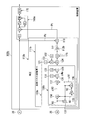
本実施形態の発電プラントは、図1に示すように、原動機としてのガスタービン10と、ガスタービン10の駆動で発電する発電機20と、制御装置100と、を備えている。
ガスタービン10は、大気を圧縮して圧縮空気を生成する空気圧縮機11と、燃料を圧縮空気中で燃焼させ高温の燃焼ガスを生成する燃焼器13と、燃焼ガスにより駆動するタービン14と、を備えている。このタービン14のロータ15と発電機20のロータ21とは機械的に接続されている。このため、タービン14のロータ15が回転すると発電機20のロータ21も回転する。タービン14のロータ15又は発電機20のロータ21には、一方のロータ15,21の回転数を検知する回転数計25が設けられている。燃焼器13には、この燃焼器13に燃料を供給する燃料ライン16が接続されている。この燃料ライン16には、燃料遮断弁17が設けられている。
発電機20と電力系統29とは、電源線22で電気的に接続されている。この電源線22には、遮断器23と、変圧器24と、発電機20の出力を検知する出力計26とが設けられている。
制御装置100は、出力計26で検知された出力の変動幅が許容出力変動幅の範囲外になったか否かに応じてガスタービン10が異常であるか否かを判断する異常判断部160と、回転数計25で検知された回転数を用いて許容出力変動幅を補正する補正部150と、異常判断部160が異常であると判断すると、操作部である燃料遮断弁17及び遮断器23に対してトリップ信号を出力するトリップ信号出力部170と、を備えている。操作部の一つである燃料遮断弁17は、このトリップ信号を受けると閉じて、燃焼器13への燃料供給が停止する。また、操作部の他の一つである遮断器23は、このトリップ信号を受けると開いて、発電機20と電力系統29との電気的な接続が断たれる。
制御装置100の異常判断部160は、出力計26からの出力の変動幅ΔPgを求める出力変動算出部167と、出力変動幅ΔPgが許容出力変動幅ΔPsの範囲外か否かを判断する許容幅判断器163と、出力変動幅ΔPgが許容出力変動幅ΔPsの範囲外になっている時間が所定時間以上であるか否かを判断するための許容外時間判断器166と、を有している。
出力変動算出部167は、出力計26からの出力に基づき参照出力Prを出力する参照出力発生器161と、参照出力Prと出力計26からの発電機20の出力Pgとの差である出力変動幅ΔPgを求める減算器162と、を有している。
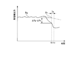
参照出力Prは、図2に示すように、ガスタービン10及び発電機20が正常運転中であるときに許容される出力変化率に基づいて求められる現時点tbの出力である。参照出力発生器161は、出力が増加した場合の増加時参照出力Pri(Pr)と、出力が減少した場合の減少時参照出力Prd(Pr)とを出力する。減算器162は、発電機20の出力Pgと増加時参照出力Priとの差である増加時出力変動幅ΔPi(ΔPg)、及び発電機20の出力Pgと減少時参照出力Prdとの差である減少時出力変動幅ΔPd(ΔPg)を求める。
なお、ここでは、参照出力Prを基準として、この参照出力Prと出力計26からの発電機20の出力Pgとの差を出力変動幅ΔPgとしているが、所定時間前の発電機20の出力を基準にして、この基準となる発電機20の出力と現時点の発電機20の出力との差を出力変動幅ΔPgとしてもよい。
許容幅判断器163は、出力が増加した場合の上限許容変動幅ΔPsiを減算器162からの出力変動幅ΔPgが超えているか否かを判断する上限判断器164と、出力が減少した場合の下限許容変動幅ΔPsdを減算器162からの出力変動幅ΔPgが超えているか否かを判断する下限判断器165と、を有する。許容幅判断器164は、減算器162からの出力変動幅ΔPgが許容出力変動幅ΔPsの範囲外であると、異常状態である旨を示す異常信号を出力する。具体的には、減算器162からの出力変動幅ΔPgが上限許容変動幅ΔPsiを超えている場合には上限判断器164が異常信号を出力し、減算器162からの出力変動幅ΔPgが下限許容変動幅ΔPsdを負側に超えている場合には下限判断器165が異常信号を出力する。
許容外時間判断器166は、タイマーを有し、許容幅判断器163からの異常信号が入力するとタイマーによるカウントダウンを開始し、この異常信号の入力が所定時間Tp(図2参照)以上継続すると、つまり、タイマーが0になると、トリップ信号出力部170に対して異常信号を出力する。
トリップ信号出力部170は、許容外時間判断器166からの異常信号が入力すると、操作部である燃料遮断弁17や遮断器23等にトリップ信号を出力する。
制御装置100の補正部150は、図1に示すように、回転数計25で検知された回転数の変動幅を求める回転数変動幅算出部151と、回転数変動幅に応じて許容出力変動幅の補正量を求める補正量演算部155と、補正量に応じて許容出力変動幅を補正する許容変動幅補正部156と、を有する。
回転数変動幅算出部151は、現時点の上参照回転数を求める上参照回転数演算器152と、現時点の下参照回転数を求める下参照回転数演算器153と、上参照回転数と下参照回転数との差を回転数変動幅として出力する減算(偏差演算)器154と、を有する。
図3に示すように、上参照回転数Nruは、回転数が定格回転数よりも高いときに低下した場合に、ガスタービン10及び発電機20が正常運転中であるときに許容される回転数低下率を用いて求められる回転数である。また、下参照回転数Nrdは、回転数が定格回転数以下のときに上昇した場合に、ガスタービン10及び発電機20が正常運転中であるときに許容される回転数上昇率を用いて求められる回転数である。減算器154は、現時点の上参照回転数Nruと現時点の下参照回転数Nrdとの差を求め、これを現時点の回転数変動幅ΔNpとして出力する。
なお、ここでの定格回転数とは、電力系統29の周波数により定まる回転数である。また、現時点の回転数変動幅ΔNpとしては、例えば、現時点から予め定めた所定時間過去までの時間における最大回転数と最小回転数との差を採用してもよい。
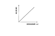
補正量演算部155は、回転数変動幅を補正量に変換する関数Fを有している。この関数Fは、例えば、図4に示すように、回転数変動幅の大きさに比例する補正量を出力する関数である。従って、補正量演算部155は、入力する回転数変動幅の大きさが大きくなれば、これに比例して大きい補正量を出力する。
許容変動幅補正部156は、図1に示すように、異常判断部160の上限判断器164が保有している上限許容変動幅ΔPsiに補正量を加える上限補正器157と、下限判断器165が保有している下限許容変動幅ΔPsdから補正量を減算する下限補正器158と、を有する。従って、回転数変動幅の大きさが大きくなれば、上限判断器164が保有している上限許容変動幅ΔPsiはより大きくなり、下限判断器165が保有している下限許容変動幅ΔPsdは負側により大きくなる。
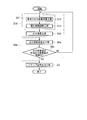
次に、図5に示すフローチャートに従って、制御装置100の処理の流れについて説明する。
制御装置100の許容変動幅補正部156は、回転数計25からの回転数を受け付けて、この回転数に基づいて異常判断部160の許容幅判断器163が保有している許容出力変動幅を補正する(補正工程(S1))。この補正工程(S1)では、まず、回転数変動幅算出部151が回転数計25からの回転数の変動幅を求める(回転数変動幅算出工程(S2))。次に、補正量演算部155が回転数変動幅の大きさに比例した補正量を求め、許容変動幅補正部156が異常判断部160の許容幅判断器163が保有している許容変動幅ΔPsを補正する(許容変動幅補正工程(S3))。具体的に、許容変動幅補正部156は、前述したように、回転数変動幅の大きさに比例して、許容幅判断器163の上限判断器164が保有している上限許容変動幅ΔPsiを大きくし、許容幅判断器163の下限判断器165が保有している下限許容変動幅ΔPsdを負側に大きくする。
以上で、補正工程(S1)が終了する。
また、以上の補正工程(S1)と並行して、異常判断部160は、ガスタービン10が異常か否かを判断する(異常判断工程(S4))。この異常判断工程(S4)では、まず、参照出力発生器161が出力計26からの出力を受け付け、この出力に基づき参照出力Prを出力する。減算器162は、この参照出力Prと出力計26からの発電機20の出力Pgとの差である出力変動幅ΔPgを求める(出力変動幅算出工程(S5))。そして、この出力変動幅ΔPgに基づいて各判断器163,166が異常か否かの判断を行う(判断工程(S6))。
この判断工程(S6)では、許容幅判断器163が減算器162から出力変動幅ΔPgを受け付け、この出力変動幅ΔPが補正部150で補正された許容出力変動幅ΔPsの範囲外か否かを判断する。そして、許容幅判断器163は、出力変動幅ΔPgが許容出力変動幅ΔPsの範囲外であると、異常状態である旨を示す異常信号を出力する。この異常信号が出力されると、許容外時間判断器166は、出力変動幅ΔPgが許容出力変動幅ΔPsの範囲外になっている時間が所定時間Tp以上であるか否かを判断し、所定時間Tp以上であれば、トリップ信号出力部170に異常信号を出力する。すなわち、この判断工程(S6)では、出力変動幅ΔPgが許容出力変動幅ΔPsの範囲外であり、且つこの状態が所定時間Tp継続すると、トリップ信号出力部170に異常信号を出力する。一方、出力変動幅ΔPgが許容出力変動幅ΔPsの範囲外ではない、又は、出力変動幅ΔPgが許容出力変動幅ΔPsの範囲外である状態が所定時間Tp継続しない場合には、ステップ1に戻る。
トリップ信号出力部170は、異常判断部160が異常信号を出力すると(S6でYesの場合)、前述したように、操作部に対してトリップ信号を出力する(S7)。この結果、ガスタービン10はトリップする。
図6に示すように、ガスタービン10の出力が一定でも、電力系統29が変動すると、発電機20の回転数と発電機20の出力とが変動する。この回転数と出力とは、極めて高い相関性があり、回転数が大きく変動すると、出力も大きく変動する。但し、回転数と出力とには、多少の位相ズレがある。
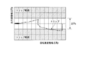
「背景技術」の欄で述べた特許文献1に記載の技術では、特許文献1では、発電機20の現在の出力と所定時間前の発電機20の出力との差と、固定値である基準値とが比較されて、ガスタービン10の状態を判定している。すなわち、図7に示すように、基準値である発電機20の出力の許容出力変動幅ΔPsは、回転数変動幅ΔNpの変化に関わらず、一定である。従って、ガスタービン10の出力が一定でも、電力系統29が変動して、発電機20の出力が大きく変動すると、例えば、図6中の時刻txでガスタービン10をトリップさせる可能性がある。
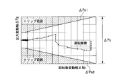
一方、本実施形態では、図8に示すように、回転数変動幅ΔNpの大きさに比例して、許容出力変動幅ΔPsを大きくしているため、より具体的には、回転数変動幅ΔNpの大きさに比例して、上限許容変動幅ΔPsiを大きくすると共に、下限許容変動幅ΔPsdを負側に大きくしている。従って、図6に示すように、電力系統29の大きな変動により、発電機20の回転数が大きく変動して、発電機20の出力も大きく変動しても、このときの出力変動幅ΔPgは許容出力変動幅ΔPsの範囲内になり、ガスタービン10をトリップさせることはない。言い換えると、本実施形態では、例えば、ガスタービン10の出力が一定のときに、電力系統29が大きく変動して、発電機20の出力も大きく変動しても、ガスタービン10が異常であるとは判断せず、ガスタービン10の運転が継続される。
以上のように、本実施形態では、電力系統29が変動した場合におけるガスタービン異常の誤検出、及びガスタービン10の誤トリップを少なくすることができる。
「第二実施形態」
次に、図9~図12を用いて、第二実施形態としての発電プラントについて説明する。
次に、図9~図12を用いて、第二実施形態としての発電プラントについて説明する。
本実施形態及び以下の実施形態の発電プラントは、いずれも、第一実施形態の制御装置100を変更したもので、その他の構成は第一実施形態の発電プラントと同じである。従って、本実施形態及び以下の実施形態については、主として、第一実施形態の制御装置100の変更内容について説明する。
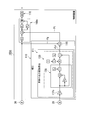
本実施形態の制御装置100aは、図9に示すように、出力の変動幅が許容出力変動幅の範囲外になったか否かに応じてガスタービン10が異常であるか否かを判断する異常判断部160aと、出力計26で検知された出力を補正する補正部110と、第一実施形態と同様のトリップ信号出力部170と、を備えている。
異常判断部160aは、補正部110からの出力Ptの変動幅ΔPを求める出力変動算出部167aと、第一実施形態と同様の許容幅判断器163及び許容外時間判断器166と、を有している。
出力変動算出部167aは、出力計26からの出力に基づき参照出力Prを出力する参照出力発生器161と、参照出力Prと補正部110からの出力Ptとの差である出力変動幅ΔPを求める減算器162aと、を有している。
参照出力発生器161は、第一実施形態と同様、出力が増加した場合の増加時参照出力Pri(Pr)と、出力が減少した場合の減少時参照出力Prd(Pr)とを出力する。減算器162aは、補正部110からの出力Ptと増加時参照出力Priとの差である増加時出力変動幅ΔPi、及び補正部110からの出力Ptと減少時参照出力Prdとの差である減少時出力変動幅ΔPdを求める。
なお、ここでは、参照出力Prを基準として、この参照出力Prと補正部110からの出力Ptとの差を出力変動幅ΔPとしているが、所定時間前の補正部110からの出力Ptを基準にして、この基準となる補正部110からの出力と現時点の補正部110からの出力との差を出力変動幅ΔPgとしてもよい。
許容幅判断器163及び許容外時間判断器166は、前述したように、第一実施形態のものと同様である。
制御装置100aの補正部110は、回転数計25で検知された回転数を用いて、ガスタービン10の見掛け上の出力変動を求める見掛け出力変動算出部111と、見掛け出力変動算出部111が求めたガスタービン10の見掛け上の出力変動と出力計26で検知された発電機20の出力Pgとを用いてガスタービン10の出力Ptを求める出力演算部118と、を有する。すなわち、この補正部110は、出力計26で検知された発電機20の出力Pgを補正することで、補正後の出力としてガスタービン10の出力Ptを出力する。
ガスタービン10の出力Ptは、以下の式(1)で示すように、出力計26で検知された発電機20の出力Pgから、ガスタービン10及び発電機20における回転系の慣性力によるガスタービン10の見掛け上の出力変動Δpを減算した値である。
Pt=Pg-Δp ・・・・・・・・・・・・・・・・・・・・・・・(1)
Pt=Pg-Δp ・・・・・・・・・・・・・・・・・・・・・・・(1)
よって、出力演算部118は、出力計26で検知された発電機20の出力Pgと、見掛け出力変動算出部111が求めたガスタービン10の見掛け上の出力変動Δpとの偏差を求める偏差演算器である。
ガスタービン10及び発電機20における回転系の慣性力によるガスタービン10の見掛け上の出力変動Δpは、以下の式(2)で表すことができる。
Δp=Tr×ω
=-I×dω/dt×ω
=-I×(2π/60)2×dN/dt×N ・・・・・・・・・・(2)
Tr:加速トルク(=-I×dω/dt)[N・m]
ω:角速度(=2πN/60)[rad/s]
I:慣性モーメント[kg・m2]
t:時間[s]
N:回転数[rpm]
=-I×dω/dt×ω
=-I×(2π/60)2×dN/dt×N ・・・・・・・・・・(2)
Tr:加速トルク(=-I×dω/dt)[N・m]
ω:角速度(=2πN/60)[rad/s]
I:慣性モーメント[kg・m2]
t:時間[s]
N:回転数[rpm]
なお、式(2)中の慣性モーメントIは、ガスタービン10及び発電機20における回転系の慣性モーメントである。このため、この慣性モーメントIは、ガスタービン10における空気圧縮機11のロータ12、タービン14のロータ15及び発電機20のロータ21を合せたものの慣性モーメントである。また、式(2)中で、時間変化に伴う変動パラメータは、回転数Nのみであり、他のパラメータは固定値である。このため、式(2)で示されるガスタービン10の見掛け上の出力変動Δpは、回転数Nを検知することで求めることができる。
図10に示すように、ガスタービン10の出力Ptが一定でも、電力系統29が変動すると、発電機20の回転数と発電機20の出力Pgとが変動する。このような電力系統29の変動に伴う発電機20の出力変動は、ガスタービン10の正味出力Ptに対して、上記式(2)に示されているガスタービン10の見掛け上の出力変動Δpとなる。従って、電力系統29が変動した場合でも、式(1)に示すように、出力計26で検知された発電機20の出力Pgからガスタービン10の見掛け上の出力変動Δpを減算することで、ガスタービン10の正味出力Ptを求めることができる。なお、ガスタービン10、発電機20及び電力系統29が安定している場合、ガスタービン10の見掛け上の出力変動Δpは実質的に「0」になる。このため、この場合、式(1)から理解できるように、ガスタービン10の出力Ptと発電機20の出力Pgとは実質的に等しくなる。
ところで、ガスタービン10及び発電機20の回転数Nが一定周期Tで変動している場合、この回転数の位相に対して発電機20の出力の位相は、理論的にはT/4だけズレる。しかしながら、複数の発電プラントにおいて、回転数計で検知された回転数の位相と出力計で検知された実際の出力の位相とを比較すると、出力計で検出された出力の位相は、回転数計で検知された回転数の位相に対してT/4よりも遅れていることが判明した。すなわち、出力計で検知される実際の出力の位相は、理論的な出力の位相に対して遅れ時間Td分遅れていることが判明した。言い換えると、ある時刻における回転数の回転数計からの出力時刻に対して、出力計は、同じある時刻における発電機の出力の出力時刻が遅れ時間Td分遅くなることが判明した。
この遅れ時間Tdの発生原因は明確に判明していないが、出力計のハードウェアーが遅れ時間の発生に起因していると考えられる。出力計は、基本的に、電流計と、電圧計と、電流計で検知された電流値と電圧計で検知された電圧値とを掛け合わせる演算器と、を有して構成されている。このように、出力計は、複数の段階を経て出力を得ているため、出力計で検知される出力の位相は、理論的な出力位相に対して遅れる、と考えられる。
式(1)を用いて、ガスタービン10の出力Ptを求める場合、式(1)中のガスタービン10の見掛け上の出力変動Δpは、式(2)を用いて前述したように、回転数が検知されれば求められる。このため、回転数から求められる見掛け上の出力変動Δpの位相は理論的な出力変動の位相と実質的に一致し、この理論的な出力変動に対して実質的に遅れていない。一方、式(1)中の発電機20の出力Pgは出力計26で検知されたものであるから、この発電機20の出力Pgの位相は理論的な出力の位相に対して遅れ時間Td分遅れている。
仮に、位相が遅れ時間Td分遅れている発電機20の出力Pgから、位相が遅れていない見掛け上の出力変動Δpを減算して、ガスタービン10の出力Ptを求めるとする。この場合、遅れ時間Tdが比較的短い時間であれば、あまり問題にならないが、遅れ時間Tdが比較的長い時間になれば、求められるガスタービン10の出力Ptに大きな誤差が含まれることになる。特に、遅れ時間Tdが回転数の変動周期Tの1/2である場合、本来、出力の正のピーク値から出力変動の正のピーク値を減算しなければならないにも関わらず、出力の正ピークの値から出力変動の負のピーク値を減算することになり、ガスタービン10の出力の変動が見掛け上の変動より極めて大きくなってしまう。
そこで、本実施形態の見掛け出力変動算出部111では、以上の知見に基づき、回転数計25で検知された回転数Nから、遅れ時間Tdを調節したガスタービン10の見掛け上の出力変動Δpを求める。具体的に、本実施形態の見掛け出力変動算出部111は、図9に示すように、回転数計25で検知された回転数Nを用いて遅れ時間Tdを考慮していないガスタービン10の見掛け上の出力変動を求める出力変動演算部120と、この見掛け上の出力変動を予め定められている遅れ時間Td分だけ遅らせる遅れ時間調節部112と、を有している。
出力変動演算部120は、互いに異なるサンプリング時刻でサンプリングされた二つの回転数を用いて回転数変化率(dN/dt)を求める回転数変化率演算部130と、ガスタービン10及び発電機20における回転系の慣性モーメントIを出力する慣性モーメント発生器121と、式(2)中の定数である〔-(2π/60)2〕を出力する定数発生器122と、複数の乗算器123,124,125と、を有している。乗算器123,124,125としては、慣性モーメントIと定数〔-(2π/60)2〕を掛け合わせる第一乗算器123と、第一乗算器123からの出力〔-I×(2π/60)2〕に回転数変化率(dN/dt)を掛ける第二乗算器124と、第二乗算器124からの出力〔-I×(2π/60)2×dN/dt〕に回転数Nを掛ける第三乗算器125と、を有している。すなわち、この出力変動演算部120は、式(2)の演算を実行する。
回転数変化率演算部130は、回転数計25からの回転数を所定時間Ts遅らせて出力する遅延器133と、回転数計25からの回転数と遅延器133からの回転数との差を求める減算器134と、所定時間Tsを出力する時間発生器132と、減算器134からの出力を時間発生器132からの所定時間Tsで割る除算器139と、を有する。すなわち、回転数変化率演算部130は、現時点の回転数と、現時点から所定時間Ts過去の回転数との平均回転数変化率を現時点の回転数変化率としている。
次に、図11に示すフローチャートに従って、制御装置100aの処理の流れについて説明する。
制御装置100aの補正部110は、回転数計25からの回転数Nと出力計26からの発電機20の出力Pgとを受け付け、この出力Pgを補正して、ガスタービン10の出力Ptを出力する(補正工程(S10))。
この補正工程(S10)では、まず、補正部110の出力変動演算部120が、ガスタービン10の見掛け上の出力変動Δpを求める(見掛け出力変動演算工程(S12))。この際、出力変動演算部120の回転数変化率演算部130が前述の方法で回転数変化率を求める。出力変動演算部120は、式(2)に従って、この回転数変化率と回転数と回転系の慣性モーメント等を用いて、ガスタービン10の見掛け上の出力変動Δpを求める。
補正工程(S10)では、続いて、遅れ時間調節部112が出力変動演算部120で求められたガスタービン10の見掛け上の出力変動Δpを遅れ時間Td前の見掛け上の出力変動Δpに調節する(遅れ時間調節工程(S13))。具体的に、遅れ時間調節部112は、遅延器であり、遅れ時間調節部112が出力変動演算部120で求められたガスタービン10の見掛け上の出力変動Δpを遅れ時間Tdだけ遅らせてから出力する。
この結果、遅れ時間調節部112から出力された見掛け上の出力変動Δpは、出力計26の遅れ時間Tdを考慮した見掛け上の出力変動となる。なお、見掛け出力変動演算工程(S12)と遅れ時間調整工程(S13)とを合わせた工程が、出力計26の遅れ時間Tdを考慮した見掛け上の出力変動を求める見掛け出力変動算出工程(S11)を成す。
補正工程(S10)では、さらに、出力演算部118が、式(1)に従って、出力計26からの発電機20の出力Pgから、見掛け出力変動算出部111で求められたガスタービン10の見掛け上の出力変動Δpを減算して、ガスタービン10の出力Ptを求める(出力演算工程(S14))。出力計26からの発電機20の出力Pgは、現時点から実質的に遅れ時間Td遅れた出力であるが、見掛け出力変動算出部111からのガスタービン10の見掛け上の出力変動Δpも、現時点から実質的に遅れ時間Td遅れた見掛け上の出力変動である。このため、出力演算部118が扱う発電機20の出力Pgとガスタービン10の見掛け上の出力変動Δpとの間には、遅れ時間Tdに基づく位相ズレがない。よって、出力演算部118は、正確なガスタービン10の出力を求めることができる。
以上で、補正工程(S10)が終了する。
異常判断部160aは、ガスタービン10が異常か否かを判断する(異常判断工程(S4a))。この異常判断工程(S4a)では、まず、参照出力発生器161が出力計26からの出力を受け付け、この出力に基づき参照出力Prを出力する。減算器162aは、この参照出力Prと補正部110からのガスタービン10の出力Ptとの差である出力変動幅ΔPを求める(出力変動幅算出工程(S5a))。そして、この出力変動幅ΔPに基づいて各判断器163,166が異常か否かの判断を行う(判断工程(S6a))。
この判断工程(S6a)では、許容幅判断器163が減算器162aから出力変動幅ΔPgを受け付け、この出力変動幅ΔPが予め定められている許容出力変動幅ΔPsの範囲外か否かを判断する。そして、許容幅判断器163は、出力変動幅ΔPgが許容出力変動幅ΔPsの範囲外であると、異常状態である旨を示す異常信号を出力する。この異常信号が出力されると、許容外時間判断器166は、出力変動幅ΔPgが許容出力変動幅ΔPsの範囲外になっている時間が所定時間Tp以上であるか否かを判断し、所定時間Tp以上であれば、トリップ信号出力部170に異常信号を出力する。
トリップ信号出力部170は、第一実施形態と同様、異常判断部160aが異常信号を出力すると(S6aでYesの場合)、前述したように、操作部に対してトリップ信号を出力する(S7)。この結果、ガスタービン10はトリップする。
例えば、図12に示すように、時刻taからガスタービン10の出力Ptが比較的に急激に減少し始めたとする。なお、図12に示すガスタービン10の出力Ptは、ガスタービン10の見掛け上の出力変動Δpを含まない正味の出力である。この結果、減少時参照出力Prd(Pr)とガスタービン10の出力Ptとの差である減少時出力変動幅ΔPd(ΔP)が生じる。ガスタービン10の出力Ptは、その後も比較的に急激に減少すると、次第に減少時出力変動幅ΔPdも負側に大きくなる。この減少時出力変動幅ΔPdが、時刻tbのときに予め定められている下限許容変動幅ΔPsd(ΔPs)を負側に超えると、下限判断器165は許容外時間判断器166へ異常信号を出力する。許容外時間判断器166は、異常信号の入力が所定時間Tp継続すると、時刻tbから所定時間Tp後の時刻tcに、トリップ信号出力部170に異常信号を出力する。この結果、トリップ信号出力部170は、前述したように、操作部に対してトリップ信号を出力し、ガスタービン10がトリップする。
以上のように、本実施形態では、例えば、電力系統29が不安定になり、ガスタービン10と発電機20との出力バランスがくずれた場合等でも、発電機20の出力から正確なガスタービン10の出力を求めることができる。
また、本実施形態では、ガスタービン10の出力Ptが一定の場合に、電力系統29の不安定に起因して発電機20の出力Pgが変動しても、以上のように正確に求められたガスタービン10の出力Ptに応じてガスタービン10が異常であるか否かの判断が行われるので、ガスタービン異常の誤検出,及びガスタービン10の誤トリップを少なくすることができる。
「第三実施形態」
次に、図13及び図14を用いて、第三実施形態としての発電プラントについて説明する。
次に、図13及び図14を用いて、第三実施形態としての発電プラントについて説明する。
本実施形態の制御装置100bは、第二実施形態の制御装置100aにおける回転数変化率演算部130を変更したもので、その他の構成は第二実施形態の制御装置100aと基本的に同じである。そこで、以下では、主として、この変更内容について説明する。
まず、本実施形態の回転数変化率演算部130bでの回転数変化率の求め方について、図14を参照して説明する。
第一時刻t1における回転数変化率を求める際には、まず、第一時刻t1に回転数計25から出力された第一回転数N1と、第一時刻t1から所定時間Ts前の第二時刻t2に回転数計25から出力された第二回転数N2とを用いて、両回転数N1,N2の差である第一回転数変化量ΔN1を求める。次に、第一時刻t1から所定時間Ts後の第三時刻t3に回転数計25から出力された第三回転数N3と第一回転数N1とを用いて、両回転数N3,N1の差である第二回転数変化量ΔN2を求める。
次に、第一回転数変化量ΔN1と第二回転数変化量ΔN2との平均値である平均変化量ΔNaを求める。次に、この平均変化量ΔNaを所定時間Tsで割って、この値を第一時刻t1における回転数変化率とする。
すなわち、ここでは、第一時刻t1と第二時刻t2との間での第一平均回転数変化率と、第一時刻t1と第三時刻t3との間での第二平均回転数変化率との平均値を第一時刻t1における回転数変化率としている。
第一時刻t1と第二時刻t2との間の所定時間Ts、及び第一時刻t1と第三時刻t3との間の所定時間Tsは、予想される遅れ時間Td以下の時間である。
ところで、第一時刻t1における回転数変化率を以上にように求める場合、第一時刻t1に対して未来の時刻である第三時刻t3における第三回転数N3が必要である。
また、出力演算部118において、第一時刻t1での回転数変化率を用いて求められる見掛け上の出力変動分が減算される対象は、第一時刻t1での発電機20の出力である。この第一時刻t1での発電機20の出力は、所定時間Tsが予想される遅れ時間Td以下の時間である関係上、第一時刻t1に対して所定時間Tsだけ未来の時刻である第三時刻t3よりもさらに未来の時刻、つまり第一時刻t1から遅れ時間Td分だけ未来の第四時刻t4に出力計26から出力される出力である。従って、第一時刻t1での発電機20の出力が得られる第四時刻t4から見ると、第三時刻t3は過去の時刻である。このため、出力演算部118において、第一時刻t1でのガスタービン10の出力を求める場合には、第三時刻t3が第四時刻t4に対して過去の時刻であるため、第一時刻t1に対して未来の時刻である第三時刻t3における第三回転数N3を得ることができる。
本実施形態の回転数変化率演算部130bは、以上の方法で回転数変化率を求める。そこで、この回転数変化率演算部130bは、図13に示すように、定数である「2」を出力する定数発生器131と、所定時間Tsを出力する時間発生器132と、回転数計25からの回転数を所定時間Ts遅らせて出力する第一遅延器133と、回転数計25からの回転数と第一遅延器133からの回転数との差を求める第一減算器134と、第一遅延器133からの回転数をさらに所定時間Ts遅らせて出力する第二遅延器135と、第一遅延器133からの回転数と第二遅延器135からの回転数との差を求める第二減算器136と、第一減算器134からの出力に第二減算器136からの出力を加える加算器137と、加算器137からの出力を定数発生器131からの「2」で割る第一除算器138と、第一除算器138からの出力を時間発生器132からの所定時間Tsで割る第二除算器139と、を有する。
ここで、この回転数変化率演算部130bにおいて、回転数計25から前述の第三時刻t3における第三回転数N3が出力されたとする。このとき、第一遅延器133は、第三時刻t3から所定時間Ts前の第一時刻t1における第一回転数N1を出力する。第一減算器134は、第一回転数N1と第三回転数N3との差である第二回転数変化量ΔN2を出力する。また、このとき、第二遅延器135は、第一時刻t1から所定時間Ts前の第二時刻t2における第二回転数N2を出力する。第二減算器136は、第一遅延器133からの出力である第一回転数N1と第二遅延器135からの出力である第二回転数N2との差である第一回転数変化量ΔN1を出力する。加算器137及び第一除算器138では、第一回転数変化量ΔN1と第二回転数変化量ΔN2との平均値である平均変化量ΔNaを求める。第二除算器139は、平均変化量ΔNaを所定時間Tsで割って、第一時刻t1における回転数変化率を出力する。
なお、以上では、平均変化量ΔNaを求めてから、この平均変化量ΔNaを所定時間Tsで割って回転数変化率を求めているが、第一回転数変化量ΔN1及び第二回転数変化量ΔN2を求めてから、これらの変化量の変化率を求め、各変化率の平均値を第一時刻t1における回転数変化率としてもよい。
ところで、図14を用いて前述したように、出力演算部118において、第一時刻t1での回転数変化率を用いて求められる見掛け上の出力変動分が減算される対象は、第一時刻t1での発電機20の出力である。この第一時刻t1での発電機20の出力は、第一時刻t1から遅れ時間Td分だけ未来の第四時刻t4に出力計26から出力される出力である。
一方、第一時刻t1での回転数変化率は、第一時刻t1から所定時間Ts分だけ未来の第三時刻t3に回転数計25から出力される回転数を用いて求められる。従って、第一時刻t1での回転数変化率が求められる時刻は、第一時刻t1から所定時間Ts分だけ未来の第三時刻t3以降になる。
このため、出力変動演算部120bが、第一時刻t1におけるガスタービン10の見掛け上の出力変動Δpを出力する時刻も、第一時刻t1から所定時間Ts分だけ未来の第三時刻t3以降になる。よって、出力変動演算部120bからの出力である見掛け上の出力変動Δpは、すでに所定時間Ts遅れているので、この見掛け上の出力変動Δpを(Td-Ts)を遅らせるだけで、この見掛け上の出力変動Δpと出力計26からの発電機20の出力との遅れ時間Td差が解消される。
そこで、本実施形態の遅れ時間調節部112bは、第二実施形態と異なり、出力変動演算部120bからの出力である見掛け上の出力変動Δpを(Td-Ts)を遅らせる。
遅れ時間調節部112bにより(Td-Ts)分遅らされた見掛け上の出力変動Δpは、見掛け出力変動算出部111bの出力として、補正部110bの出力演算部118に送られる。出力演算部118では、第二実施形態と同様に、出力計26からの出力Pgから、見掛け出力変動算出部111bからの見掛け上の出力変動Δpが減算されて、減算結果であるガスタービン10の正味出力が異常判断部160aに出力される。
以上、本実施形態では、3つの時刻から回転数変化率を求めているので、より正確な回転数変化率を求めることできる。本実施形態では、図14に示すように、時刻t1を基準にして、この時刻t1と過去の時刻t2との間の平均回転数変化率のみならず、この時刻t1と未来の時刻t3との間の平均回転数変化率も使って、これら平均回転数変化率の平均値を時刻t1での回転数変化率としている。このため、本実施形態では、回転数変化率を求める時刻t1での回転数が極大値又は極小値をとるときには、第二実施形態よりもより正確な回転数変化率を求めることができる。
「第四実施形態」
次に、図15を用いて、第四実施形態としての発電プラントについて説明する。
次に、図15を用いて、第四実施形態としての発電プラントについて説明する。
本実施形態の制御装置100cは、第二実施形態の制御装置100aにおける遅れ時間調節部112の位置を変更したもので、その他の構成は第二実施形態の制御装置100aと基本的に同じである。従って、以下では、主として、この変更内容について説明する。
第二実施形態の遅れ時間調節部112は、見掛け出力変動演算部120と出力演算部118との間に配置されている。一方、本実施形態の遅れ時間調節部112cは、回転数計25と見掛け出力変動演算部120との間に配置されている。
本実施形態では、回転数計25で検知された回転数が遅れ時間調節部112cにより見掛け時間Td遅らされてから、見掛け出力変動演算部120に入力する。この結果、見掛け出力変動演算部120で求められたガスタービン10の見掛け上の出力変動Δpは、既に見掛け時間Td分遅れていることになる。このため、本実施形態では、第二実施形態のように、見掛け出力変動演算部120から見掛け上の出力変動Δpは、遅れ時間調節されることなく、出力演算部118に入力する。
以上のように、出力計26からの出力の遅れに対する出力変動の遅れ時間調節は、第一実施形態のように、見掛け出力変動演算部120の出力であるガスタービン10の見掛け上の出力変動に対して行っても、本実施形態のように、見掛け出力変動演算部120の入力値である回転数に対して行ってもよい。よって、第三実施形態においても、本実施形態と同様に、遅れ時間調節部を回転数計25と見掛け出力変動演算部120bとの間に配置してもよい。また、第三実施形態では、見掛け出力変動演算部120bにおける第一遅延器133及び第二遅延器135で回転数を遅らせる所定時間Tsを遅れ時間Tdに設定することでも、遅れ時間調節を実行することができる。
なお、以上の実施形態は、いずれも、ガスタービンが原動機の発電プラントであるが、原動機はガスタービンに限定されるものではなく、例えば、蒸気タービンや風車等であってもよい。
本発明の一態様によれば、ガスタービン中の高温部の冷却を図りつつ、圧縮機から抽気した圧縮空気の熱を有効利用することができる。
10…ガスタービン、11:空気圧縮機、13:燃焼器、14:タービン、17:燃料遮断弁、20:発電機、23:遮断器、25:回転数計、26:出力計、100,100a,100b,100c:制御装置、110,110b:補正部、111,111b:見掛け出力変動算出部、112,112a,112b,112c:遅れ時間調節部、120,120b:出力変動演算部、130,130b:回転数変化率演算部、160,160a:異常判断部、170:トリップ信号出力部
Claims (17)
- 発電機に機械的に接続されている原動機の異常検出方法において、
出力計で検知された前記発電機の出力の変動幅が許容出力変動幅の範囲外になったか否かに応じて、前記原動機が異常であるか否かを判断する異常判断工程と、
前記異常判断工程での判断基準となる前記許容出力変動幅と、前記異常判断工程での判断対象となる前記出力計で検知された前記出力とのうちの一方を、回転数計で検知された前記発電機と前記原動機とのうちの一方の回転数を用いて補正する補正工程と、
を実行する、
原動機の異常検出方法。 - 請求項1に記載の原動機の異常検出方法において、
前記補正工程では、前記一方の回転数を用いて、前記回転数の回転数変動幅を求める回転数変動幅算出工程と、前記回転数変動幅が大きくなるに連れて、前記許容出力変動幅が大きくなるよう、前記許容出力変動幅を補正する許容変動幅補正工程と、を実行し、
前記異常判断工程では、前記出力計で検知された前記出力の変動幅が前記補正工程で補正された前記許容出力変動幅の範囲外になったか否かに応じて、前記原動機が異常であるか否かを判断する、
原動機の異常検出方法。 - 請求項2に記載の原動機の異常検出方法において、
前記回転数変動幅算出工程では、
前記回転数が定格回転数よりも高いときに低下した場合に、前記原動機及び前記発電機が正常運転中であるときに許容される回転数低下率を用いて求められる回転数である上参照回転数を求める上参照回転数演算工程と、
前記回転数が定格回転数以下のときに上昇した場合に、前記原動機及び前記発電機が正常運転中であるときに許容される回転数上昇率を用いて求められる回転数である下参照回転数であって、前記上参照回転数と同じ時刻における下参照回転数を求める下参照回転数演算工程と、
前記上参照回転数と前記下参照回転数との差を求め、前記差を前記回転数変動幅として出力する偏差演算工程と、
を実行する、
原動機の異常検出方法。 - 請求項2又は3に記載の原動機の異常検出方法において、
前記異常判断工程では、前記出力計で検知された前記出力と前記出力に対する基準出力との差を前記出力の変動とする出力変動算出工程を実行する、
原動機の異常検出方法。 - 請求項1に記載の原動機の異常検出方法において、
前記補正工程では、前記一方の回転数と、前記回転数の単位時間当たりの変化率である回転数変化率と、前記原動機及び前記発電機における回転系の慣性モーメントとを用いて、前記原動機の見掛け上の出力変動を求め、前記出力計で検知された前記発電機の出力から前記見掛け上の出力変動分を減算した値を、補正された出力とし、
前記異常判断工程では、前記補正工程で補正された前記出力の変動幅が前記許容出力変動幅の範囲外になったか否かに応じて、前記原動機が異常であるか否かを判断する、
原動機の異常検出方法。 - 請求項5に記載の原動機の異常検出方法において、
前記補正工程では、前記出力計から出力された前記出力から、前記回転数計からの出力に対する前記出力計からの出力の遅れ時間分遅れている前記見掛け上の出力変動を減算する、
原動機の異常検出方法。 - 請求項5又は6に記載の原動機の異常検出方法において、
前記異常判断工程では、前記補正工程で補正された前記出力と前記出力計で検知された前記出力に対する基準出力との差を前記出力の変動とする出力変動算出工程を実行する、
原動機の異常検出方法。 - 請求項4又は7に記載の原動機の異常検出方法において、
前記出力変動算出工程では、前記原動機及び前記発電機が正常運転中であるときに許容される出力変化率を用いて求められる出力である参照出力を前記基準出力とする、
原動機の異常検出方法。 - 発電機に機械的に接続されている原動機の制御装置において、
出力計で検知された前記発電機の出力の変動幅が許容出力変動幅の範囲外になったか否かに応じて、前記原動機が異常であるか否かを判断する異常判断部と、
前記異常判断部での判断基準となる前記許容出力変動幅と前記異常判断部での判断対象となる前記出力計で検知された前記出力とのうちの一方を、回転数計で検知された前記発電機と前記原動機とのうちの一方の回転数を用いて補正する補正部と、
前記異常判断部で前記原動機が異常であると判断されると、前記原動機をトリップさせることができる操作部にトリップ信号を出力して、前記原動機をトリップさせるトリップ信号出力部と、
を備えている原動機の制御装置。 - 請求項9に記載の原動機の制御装置において、
前記補正部は、前記一方の回転数を用いて、前記回転数の回転数変動幅を求める回転数変動幅算出部と、前記回転数変動幅が大きくなるに連れて、前記許容出力変動幅が大きくなるよう、前記許容出力変動幅を補正する許容変動幅補正部と、を有し、
前記異常判断部は、前記出力計で検知された前記出力の変動幅が前記補正部で補正された前記許容出力変動幅の範囲外になったか否かに応じて、前記原動機が異常であるか否かを判断する
原動機の制御装置。 - 請求項10に記載の原動機の制御装置において、
前記回転数変動幅算出部は、
前記回転数が定格回転数よりも高いときに低下した場合に、前記原動機及び前記発電機が正常運転中であるときに許容される回転数低下率を用いて求められる回転数である上参照回転数を求める上参照回転数演算部と、
前記回転数が定格回転数以下のときに上昇した場合に、前記原動機及び前記発電機が正常運転中であるときに許容される回転数上昇率を用いて求められる回転数である下参照回転数であって、前記上参照回転数と同じ時刻における下参照回転数を求める下参照回転数演算部と、
前記上参照回転数と前記下参照回転数との差を求め、前記差を前記回転数変動幅として出力する偏差演算部と、
を有する、
原動機の制御装置。 - 請求項10又は11に記載の原動機の制御装置において、
前記異常判断部は、前記出力計で検知された前記出力と前記出力に対する基準出力との差を前記出力の変動とする出力変動算出部を有する、
原動機の制御装置。 - 請求項9に記載の原動機の制御装置において、
前記補正部は、
前記一方の回転数と、前記回転数の単位時間当たりの変化率である回転数変化率と、前記原動機及び前記発電機における回転系の慣性モーメントとを用いて、前記原動機の見掛け上の出力変動を求める見掛け出力変動算出部と、
前記出力計で検知された前記発電機の出力から前記見掛け上の出力変動分を減算した値を、補正された出力する出力演算部と、
を有し、
前記異常判断部は、前記補正部が補正した前記出力の変動幅が前記許容出力変動幅の範囲外になったか否かに応じて、前記原動機が異常であるか否かを判断する、
原動機の制御装置。 - 請求項13に記載の原動機の制御装置において、
前記補正部は、前記出力演算部に入力する前記見掛け上の出力変動を、前記回転数計からの出力に対する前記出力計からの出力の遅れ時間分遅らせる遅れ時間調節部を有する、
原動機の制御装置。 - 請求項13又は14に記載の原動機の制御装置において、
前記異常判断部は、前記補正部が補正した前記出力と前記出力計で検知された前記出力に対する基準出力との差を前記出力の変動とする出力変動算出部を有する、
原動機の制御装置。 - 請求項12又は15に記載の原動機の制御装置において、
前記出力変動算出部は、前記原動機及び前記発電機が正常運転中であるときに許容される出力変化率を用いて求められる出力である参照出力を前記基準出力とする、
原動機の制御装置。 - 請求項9から16のいずれか一項に記載の原動機の制御装置と、
前記原動機と、
前記発電機と、
前記操作部と、
を備えている発電プラント。
Priority Applications (2)
| Application Number | Priority Date | Filing Date | Title |
|---|---|---|---|
| KR1020157020718A KR101716599B1 (ko) | 2013-03-28 | 2014-03-26 | 원동기의 이상 검출 방법, 이 방법을 실행하는 원동기의 제어 장치, 및 이 장치를 구비하고 있는 발전 플랜트 |
| CN201480005480.9A CN104937218B (zh) | 2013-03-28 | 2014-03-26 | 动力机的异常检测方法、控制装置及具该装置的发电设备 |
Applications Claiming Priority (2)
| Application Number | Priority Date | Filing Date | Title |
|---|---|---|---|
| JP2013070571A JP6082299B2 (ja) | 2013-03-28 | 2013-03-28 | 原動機の異常検出方法、この方法を実行する原動機の制御装置、及びこの装置を備えている発電プラント |
| JP2013-070571 | 2013-03-28 |
Publications (1)
| Publication Number | Publication Date |
|---|---|
| WO2014157277A1 true WO2014157277A1 (ja) | 2014-10-02 |
Family
ID=51624243
Family Applications (1)
| Application Number | Title | Priority Date | Filing Date |
|---|---|---|---|
| PCT/JP2014/058419 Ceased WO2014157277A1 (ja) | 2013-03-28 | 2014-03-26 | 原動機の異常検出方法、この方法を実行する原動機の制御装置、及びこの装置を備えている発電プラント |
Country Status (4)
| Country | Link |
|---|---|
| JP (1) | JP6082299B2 (ja) |
| KR (1) | KR101716599B1 (ja) |
| CN (1) | CN104937218B (ja) |
| WO (1) | WO2014157277A1 (ja) |
Cited By (1)
| Publication number | Priority date | Publication date | Assignee | Title |
|---|---|---|---|---|
| CN119801742A (zh) * | 2024-11-18 | 2025-04-11 | 中国航发沈阳发动机研究所 | 一种基于转速上升率判断供油异常的供油控制方法及装置 |
Families Citing this family (4)
| Publication number | Priority date | Publication date | Assignee | Title |
|---|---|---|---|---|
| JP6173367B2 (ja) * | 2015-02-03 | 2017-08-02 | 三菱日立パワーシステムズ株式会社 | 状態判定装置、運転制御装置、ガスタービン及び状態判定方法 |
| CN108702311B (zh) * | 2016-03-10 | 2020-11-27 | 三菱电机株式会社 | 接收装置和事态检测时刻的估计方法 |
| CN109633442A (zh) * | 2018-12-27 | 2019-04-16 | 新疆金风科技股份有限公司 | 发电机转速波动的检测方法、装置、设备及存储介质 |
| CN113719429A (zh) * | 2021-09-01 | 2021-11-30 | 中国船舶重工集团海装风电股份有限公司 | 一种风电机组转速振荡状态识别方法、装置及存储介质 |
Citations (3)
| Publication number | Priority date | Publication date | Assignee | Title |
|---|---|---|---|---|
| JPS5943910A (ja) * | 1982-09-03 | 1984-03-12 | Hitachi Ltd | 冷熱発電設備用タ−ビンの異常検出方法 |
| JPS606003A (ja) * | 1983-06-24 | 1985-01-12 | Toshiba Corp | タ−ビン入出力不平衡検出装置 |
| JPS61104259A (ja) * | 1984-10-26 | 1986-05-22 | Mitsubishi Electric Corp | 回転数検出装置の自動点検装置 |
Family Cites Families (9)
| Publication number | Priority date | Publication date | Assignee | Title |
|---|---|---|---|---|
| JPH066003A (ja) * | 1992-06-18 | 1994-01-14 | Hitachi Ltd | フレキシブルサーキット及びその製造方法 |
| JPH1164127A (ja) * | 1997-08-13 | 1999-03-05 | Mitsubishi Heavy Ind Ltd | 軸系負荷発生源の負荷急減検知方法とその装置 |
| US6457461B1 (en) * | 2001-05-04 | 2002-10-01 | Detroit Diesel Corporation | EGR and VGT system diagnostics and control |
| CN201623457U (zh) * | 2010-03-09 | 2010-11-03 | 杭州浙大威尔科技有限公司 | 具有转速超越报警功能的汽轮机超速保护装置 |
| IT1401427B1 (it) * | 2010-08-11 | 2013-07-26 | Nuova Pignone S R L | Metodi e dispositivi usati per controllare automaticamente la velocita di un espansore |
| EP2469041A1 (en) * | 2010-12-22 | 2012-06-27 | Siemens Aktiengesellschaft | Method of detecting a predetermined condition in a gas turbine and failure detection system for a gas turbine |
| JP5653786B2 (ja) * | 2011-02-09 | 2015-01-14 | 三菱重工業株式会社 | 異常検出装置 |
| JP5792087B2 (ja) * | 2011-04-20 | 2015-10-07 | 新日鐵住金株式会社 | 蒸気供給システム及びその制御方法 |
| CN102709948B (zh) * | 2012-06-18 | 2014-12-10 | 武汉长海高新技术有限公司 | 一种余热回收汽轮发电机组综合控制与保护装置及综合控制与保护方法 |
-
2013
- 2013-03-28 JP JP2013070571A patent/JP6082299B2/ja active Active
-
2014
- 2014-03-26 CN CN201480005480.9A patent/CN104937218B/zh active Active
- 2014-03-26 WO PCT/JP2014/058419 patent/WO2014157277A1/ja not_active Ceased
- 2014-03-26 KR KR1020157020718A patent/KR101716599B1/ko active Active
Patent Citations (3)
| Publication number | Priority date | Publication date | Assignee | Title |
|---|---|---|---|---|
| JPS5943910A (ja) * | 1982-09-03 | 1984-03-12 | Hitachi Ltd | 冷熱発電設備用タ−ビンの異常検出方法 |
| JPS606003A (ja) * | 1983-06-24 | 1985-01-12 | Toshiba Corp | タ−ビン入出力不平衡検出装置 |
| JPS61104259A (ja) * | 1984-10-26 | 1986-05-22 | Mitsubishi Electric Corp | 回転数検出装置の自動点検装置 |
Cited By (1)
| Publication number | Priority date | Publication date | Assignee | Title |
|---|---|---|---|---|
| CN119801742A (zh) * | 2024-11-18 | 2025-04-11 | 中国航发沈阳发动机研究所 | 一种基于转速上升率判断供油异常的供油控制方法及装置 |
Also Published As
| Publication number | Publication date |
|---|---|
| KR101716599B1 (ko) | 2017-03-14 |
| JP2014194173A (ja) | 2014-10-09 |
| JP6082299B2 (ja) | 2017-02-15 |
| CN104937218A (zh) | 2015-09-23 |
| CN104937218B (zh) | 2016-09-28 |
| KR20150100940A (ko) | 2015-09-02 |
Similar Documents
| Publication | Publication Date | Title |
|---|---|---|
| JP6082299B2 (ja) | 原動機の異常検出方法、この方法を実行する原動機の制御装置、及びこの装置を備えている発電プラント | |
| JP4879319B2 (ja) | 周波数測定装置 | |
| EP2963759A1 (en) | Power conversion device for connection to grid | |
| JP6456650B2 (ja) | モータ制御装置、圧縮機、空気調和機およびプログラム | |
| EP3454469A1 (en) | Torque ripple reduction for a generator | |
| JP2014194173A5 (ja) | ||
| CA2982798C (en) | Method for detecting an imminent pole slip | |
| JP2019201471A (ja) | モータ制御装置 | |
| JP5071500B2 (ja) | 原動機出力の制御装置 | |
| US9991835B2 (en) | Control device for electric compressor | |
| CN115186497B (zh) | 高周切机方案定值确定方法、系统、存储介质及计算设备 | |
| JP2014194174A (ja) | 原動機の出力算出方法、この方法を用いた原動機の異常検出方法、これらの方法を実行する装置、及びこの装置を備えている発電プラント | |
| JP4716680B2 (ja) | 永久磁石型同期電動機の制御装置 | |
| JP2019180173A (ja) | モータ制御装置 | |
| JP2015001212A (ja) | 風力発電機の出力制御装置及び出力制御方法、並びに風力発電システム | |
| US11566601B2 (en) | Device and method for angle stabilization of a virtual synchronous machine | |
| JP5693337B2 (ja) | 発電機の制御装置 | |
| JP6984672B2 (ja) | モータ制御装置 | |
| JP6724412B2 (ja) | エンジンベンチシステムの制御装置 | |
| EP3576290B1 (en) | Angle determination for a generator | |
| JP5511531B2 (ja) | 同期電動機の制御装置 | |
| JP2014194175A (ja) | 遅れ時間の算出方法、原動機の出力算出方法、状態量の制御方法、これらの方法を実行する装置 | |
| KR101979165B1 (ko) | 2개의 서브-샤프트를 결합하기 위한 방법 | |
| EP3576289A1 (en) | Power system | |
| KR20050049573A (ko) | 전압의 주파수 편이를 이용한 동기탈조 검출방법 |
Legal Events
| Date | Code | Title | Description |
|---|---|---|---|
| 121 | Ep: the epo has been informed by wipo that ep was designated in this application |
Ref document number: 14776319 Country of ref document: EP Kind code of ref document: A1 |
|
| ENP | Entry into the national phase |
Ref document number: 20157020718 Country of ref document: KR Kind code of ref document: A |
|
| NENP | Non-entry into the national phase |
Ref country code: DE |
|
| 122 | Ep: pct application non-entry in european phase |
Ref document number: 14776319 Country of ref document: EP Kind code of ref document: A1 |