WO2014156865A1 - センサ、およびそれを用いた回転電機 - Google Patents
センサ、およびそれを用いた回転電機 Download PDFInfo
- Publication number
- WO2014156865A1 WO2014156865A1 PCT/JP2014/057491 JP2014057491W WO2014156865A1 WO 2014156865 A1 WO2014156865 A1 WO 2014156865A1 JP 2014057491 W JP2014057491 W JP 2014057491W WO 2014156865 A1 WO2014156865 A1 WO 2014156865A1
- Authority
- WO
- WIPO (PCT)
- Prior art keywords
- hall
- magnetic flux
- sensor
- magnet
- leg
- Prior art date
- Legal status (The legal status is an assumption and is not a legal conclusion. Google has not performed a legal analysis and makes no representation as to the accuracy of the status listed.)
- Ceased
Links
Images






Classifications
-
- H—ELECTRICITY
- H02—GENERATION; CONVERSION OR DISTRIBUTION OF ELECTRIC POWER
- H02K—DYNAMO-ELECTRIC MACHINES
- H02K29/00—Motors or generators having non-mechanical commutating devices, e.g. discharge tubes or semiconductor devices
- H02K29/06—Motors or generators having non-mechanical commutating devices, e.g. discharge tubes or semiconductor devices with position sensing devices
- H02K29/08—Motors or generators having non-mechanical commutating devices, e.g. discharge tubes or semiconductor devices with position sensing devices using magnetic effect devices, e.g. Hall-plates, magneto-resistors
Definitions
- the present invention relates to a sensor that detects a rotational position of a rotor, and a rotating electrical machine such as a motor or a generator that uses the sensor.
- a rotating electrical machine such as a starter generator of a vehicle is provided with a position detection sensor such as a Hall IC that detects the rotational position of the rotor, and the commutation timing of the three-phase coil based on the detection signal detected by the position detection sensor.
- a position detection sensor such as a Hall IC that detects the rotational position of the rotor, and the commutation timing of the three-phase coil based on the detection signal detected by the position detection sensor.
- a position detection sensor used in this type of rotating electrical machine, a sensor element such as a Hall IC is housed in a sensor case together with a circuit board, and the sensor case is installed on the fixed part side of the rotating electrical machine.
- the sensor case is formed with four leg portions, and the four sensor elements are inserted and held in the four leg portions one by one.
- the sensor element held by each leg has a lead wire extending toward the base of the leg, and is provided on a circuit board provided in the sensor case so as to be positioned in a plane perpendicular to the protruding direction of the leg. Connected by soldering.
- the present invention provides a sensor capable of reducing the size of a position detection sensor, and a rotating electrical machine using the sensor.
- the sensor for detecting the change in the magnetic flux of the rotating magnet is disposed apart from the sensor case body along the rotation direction of the magnet, First to third leg portions projecting so as to face the magnet in a direction orthogonal to the rotation direction of the magnet, and first to fourth Hall ICs for detecting a change in magnetic flux are provided. .
- First and second magnetic flux passage portions that allow the magnetic flux of the magnet to pass through are set in the first leg portion along the extending direction of the first leg portion.
- a third magnetic flux passage portion that allows the magnetic flux of the magnet to pass is set in the second leg portion.
- a fourth magnetic flux passage portion that allows the magnetic flux of the magnet to pass is set in the third leg portion.
- the first Hall IC is accommodated at a position corresponding to the first magnetic flux passage portion in the first leg portion, and the second magnetic flux is provided.
- the second Hall IC is accommodated in a position corresponding to the passage portion
- the third Hall IC is accommodated in a position corresponding to the third magnetic flux passage portion in the second leg portion
- the fourth Hall IC may be accommodated in a position corresponding to the fourth magnetic flux passage portion in the three leg portions.
- the first to fourth Hall ICs may be provided with leads, but the first to fourth Hall ICs are respectively the first to third Hall ICs. It may be mounted on a substrate inserted into the leg portion of the.
- the Hall IC is a so-called chip Hall IC mounted on a substrate, so that the Hall IC does not have a lead wire and can be made compact. Further, by mounting the Hall IC on the substrate, it is only necessary to position the substrate with respect to the leg portion, and the Hall IC can be installed with high positional accuracy.
- the substrate may be arranged along a direction in which the first to third legs are arranged.
- the position of the substrate in the radial direction of the sensor can be suppressed by arranging the substrate in the direction in which the three legs are aligned (the circumferential direction of the sensor).
- the first Hall IC and the second Hall IC are arranged along the protruding direction of the first leg on the same substrate. It may be.
- the detection waveform output from the first Hall IC and the detection waveform output from the second Hall IC can be synchronized.
- the sensor is a position detection sensor for a starter generator.
- the first Hall IC is for ignition timing for detecting the ignition timing of the engine.
- the second to fourth Hall ICs detect the commutation timing of the starter generator coil.
- the second to fourth Hall ICs are arranged on the same line.
- the first Hall IC is disposed at a position shifted from the line on which the second to fourth Hall ICs are disposed. In the magnet, the arrangement of the magnetic poles at positions facing the first Hall IC and the arrangement of the magnetic poles at positions facing the second to fourth Hall ICs are partially different.
- the substrate protrudes from the insertion portion inserted into the first to third leg portions and the first to third leg portions, and is connected to a lead wire.
- a lead wire connecting portion, forming the first to third leg portions, surrounding the sensor holder into which the insertion portion of the substrate is inserted, and the lead wire connecting portion protruding from the insertion portion The sensor case body may be a separate member.
- the lead wire when assembling the sensor, after inserting the board insertion part into the leg part of the sensor holder, the lead wire is connected to the lead wire connection part of the board protruding from the leg part, and then the lead A sensor case body surrounding the line connecting portion can be attached to the sensor holder.
- the sensor case main body surrounding the lead wire is not attached, and therefore the lead wire connection work can be easily performed.
- the substrates are connected by jumper wires.
- a jumper wire is bent.
- substrate can be arrange
- the rotating electrical machine includes a stator having a plurality of teeth portions around which coils are wound in the circumferential direction, and is disposed on the outer circumferential side of the stator, and the magnet is disposed on the inner circumferential surface in the circumferential direction.
- a sensor according to any one of the first to eighth aspects of the present invention, wherein the sensor is disposed on an outer peripheral portion of the stator and detects a rotational position of the rotor. And comprising.
- three leg portions can be provided while four Hall ICs are provided.
- the length in the circumferential direction (direction in which the leg portions are arranged in an arc) of the sensor can be reduced. For this reason, it becomes possible to reduce the size of the sensor.
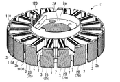
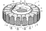
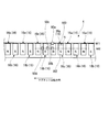
- FIG. 1 It is a perspective view of the rotary electric machine of one Embodiment of this invention. It is sectional drawing of the rotary electric machine of one Embodiment of this invention. It is a perspective view which shows the stator which comprises the rotary electric machine of one Embodiment of this invention. It is a perspective view which shows the stator which comprises the rotary electric machine of one Embodiment of this invention. It is an expanded view of the inner peripheral side of the rotor of one Embodiment of this invention. It is a timing chart which shows the detection state of each sensor element of the position detection sensor of one embodiment of this invention, and the output waveform of each phase of U, V, and W.
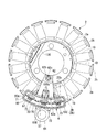
- FIG. 1 It is a perspective view of the stator provided with the position detection sensor of one Embodiment of this invention. It is a top view of the stator provided with the position detection sensor of one Embodiment of this invention. It is a perspective view which shows the attachment state to the stator of the position detection sensor of one Embodiment of this invention. It is a perspective view of the position detection sensor of one Embodiment of this invention. It is a perspective view of the sensor case main body of one Embodiment of this invention. It is a perspective view which shows the sensor holder of one Embodiment of this invention. It is a perspective developed view which shows the assembly
- FIG. 1 and 2 show a rotating electrical machine 1 of this embodiment used as a starter generator for a vehicle engine.
- the rotating electrical machine 1 is a three-phase brushless rotating electrical machine.
- the rotating electrical machine 1 includes a stator 2 fixed to an engine block (not shown), a rotor 4 fixed to a crankshaft (not shown) of the engine, and a position detection sensor 6 that detects the rotational position of the rotor 4. It has.
- the stator 2 includes a stator iron core 2A formed by laminating electromagnetic steel plates, and a plurality of coils 10 wound around the stator iron core 2A.
- the stator iron core 2A has a main body 2a formed in an annular shape and a plurality of teeth 2b projecting radially outward from the outer peripheral surface of the main body 2a. At the tip of each tooth portion 2b, claw pieces 3 projecting in a substantially T shape are provided on both sides in the circumferential direction.
- an insulator 110 is mounted on the outer surface of the stator core 2A so as to cover the peripheral area of each tooth portion 2b.
- the insulator 110 is composed of two insulator members 110A and 110B that are divided into two substantially in the axial direction.
- the stator 2 includes a coil connection terminal 120 molded on the insulator member 110A.
- the coil 10 is wound around the periphery of each tooth portion 2 b via an insulator 110.
- the rotor 4 includes a bottomed cylindrical rotor yoke 12 made of a magnetic material, and a boss portion 14 coaxially fixed to the bottom wall 12 a of the rotor yoke 12.
- An engine crankshaft is coupled to the boss portion 14 so as to be integrally rotatable.
- FIG. 4 shows the inner peripheral side of the rotor 4 in a developed state.
- a plurality of magnets 16 are attached to the inner peripheral surface of the rotor 4 at equal intervals along the circumferential direction.
- Each of these magnets 16 is formed in a rectangular shape that is long in the axial direction of the rotor 4.
- the surface (inner surface) facing toward the center of the rotor 4 is magnetized to either the N pole or the S pole.
- One magnet 16c has a short sub magnetic pole portion whose inner side surface is magnetized to S pole on one end side (one end side in the longitudinal direction) of the main magnetic pole portion 162 whose inner side surface is magnetized to N pole. 160 is provided.
- the magnet 16 a having the entire inner side surface magnetized to the N pole, the magnet 16 a, the magnet 16 having the entire inner side surface magnetized to the S pole, the magnet 16 b, the main magnetic pole portion 162 and the sub-magnetic pole.
- the magnet 16 having the portion 160 is a magnet 16c
- the magnet 16c is disposed between a specific pair of adjacent magnets 16a and 16a, and the magnet 16b is disposed between the other adjacent magnets 16a and 16a. Is placed.
- the N pole and the S pole appear alternately on the inner peripheral side of the rotor 4 except for one end side in the axial direction (upper end side in FIG. 4).
- N poles appear continuously by the auxiliary magnetic pole portion 160 of the magnet 16c and three magnets before and after (subsequently in the circumferential direction) the magnet.
- the region on one end side in the axial direction of the magnet 16 is used as a target for detecting the ignition timing of the engine.
- the remaining area in the axial direction of the magnet 16 is mainly used as a target for detecting the commutation timing of the coil 10.
- the coil 10 wound around the tooth portion 2b of the stator core 2A is pulled out of the stator 2 and connected to a control device (not shown).
- the control device rotates the rotor 4 and the crankshaft by supplying current to the coil 10 at a predetermined timing when the engine is started. Further, after the engine is started, the generated power accompanying the rotation of the rotor 4 is charged in a battery (not shown) or directly used.
- the lead wire 100 b is connected to the coil 10.
- the plurality of lead wires 100b are bundled by the protection tube 102b, and the periphery is covered with the protection tube 102b.
- lead wires 100 a drawn out from a sensor case 60 described later are bundled by a protective tube 102 a, and the periphery is covered by the protective tube 102.
- the shape of the claw piece 3 of each tooth portion 2b is not a fixed shape, and as shown in FIGS.
- a notch 7 is provided.
- the notch 7 is formed so as to form a substantially rectangular fitting groove across two claw pieces 3 adjacent in the circumferential direction.
- pairs of the notch portions 7 that form the fitting groove are arranged in a total of three locations in the circumferential direction.
- a pair of notches 7 formed in the adjacent specific teeth 2B includes a sensor holding leg (first leg) 80a and a leg (second leg) of the position detection sensor 6 described later. ) 80b and a leg (third leg) 80c (see FIG. 2) are inserted and arranged.
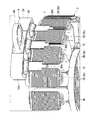
- the leg portions 80a, 80b and 80c of the position detection sensor 6 accommodate first, second, third and fourth Hall ICs (sensor elements) 50a, 50b, 50c and 50d, respectively. Is arranged. These Hall ICs 50a, 50b, 50c, 50d are opposed to the inner peripheral surface of the rotor 4 and detect the switching of the magnetic flux of the magnet 16. That is, the place where the first Hall IC 50a of the leg portion 80a is accommodated is set to the first magnetic flux passage portion 180a through which the magnetic flux of the magnet 16 passes. The place where the second Hall IC 50b of the leg portion 80a is accommodated is set in the second magnetic flux passage portion 180b through which the magnetic flux of the magnet 16 passes.
- the place where the third Hall IC 50c of the leg portion 80b is accommodated is set in the fourth magnetic flux passage portion 180c that allows the magnetic flux of the magnet 16 to pass therethrough.
- the place where the fourth Hall IC 50d of the leg portion 80c is accommodated is set to the fourth magnetic flux passage portion 180d that allows the magnetic flux of the magnet 16 to pass therethrough.
- the installation height is the first Hall IC 50a and the second, third, and fourth Hall ICs 50b, 50c, 50d. Is different. That is, the first Hall IC 50 a is disposed at a position M ⁇ b> 1 that faces one end side in the axial direction of the inner peripheral surface of the rotor 4. The second, third, and fourth Hall ICs 50b, 50c, and 50d are disposed at a position M2 that faces the central side in the axial direction of the inner peripheral surface of the rotor 4.
- the second, third, and fourth Hall ICs 50 b, 50 c, 50 d are arranged on the same line in the rotation direction of the rotor 4.
- the first Hall IC 50a is arranged at a position shifted from the line where the second, third and fourth Hall ICs 50b, 50c, 50d are arranged.
- the first Hall IC 50a and the second Hall IC 50b are arranged so as to be located on the same line in the direction orthogonal to the rotation direction of the rotor 4, that is, in the axial direction (details will be described later).
- the first Hall IC 50a detects the switching of the magnetic flux of the magnets 16a, 16b, and 16c at a height that passes through the sub magnetic pole part 160 of the magnet 16c.
- the second, third, and fourth Hall ICs 50b, 50c, and 50d detect the switching of the magnetic flux of the magnets 16a, 16b, and 16c at a height that passes through the main magnetic pole portion 162 of the magnet 16c.
- the second, third, and fourth Hall ICs 50b, 50c, and 50d output the signal detected at the position M2 on the center side of the rotor 4 to the control device as the rotational position signal of the rotor 4.
- the first Hall IC 50a outputs a signal detected at the position M1 on one end side in the axial direction of the rotor 4 to the control device as an absolute position information signal on the circumference of the rotor 4.
- the control device receives the output signals of the second, third, and fourth Hall ICs 50b, 50c, and 50d, controls the commutation timing for the three-phase coil 10, and outputs the output signal of the first Hall IC 50a; In response to the output signals of the second, third, and fourth Hall ICs 50b, 50c, and 50d, the ignition timing and fuel injection timing of the engine are controlled.
- FIG. 5 is a timing in which signals generated by the control device according to the outputs of the Hall ICs 50a, 50b, 50c, and 50d and voltage waveforms output to the coils 10 of the U, V, and W phases are described. It is a chart.
- S2, S3, and S4 indicate pulse signals generated corresponding to the outputs of the second, third, and fourth Hall ICs 50b, 50c, and 50d.
- S1 indicates a pulse signal generated corresponding to the output of the first Hall IC 50a.
- Sv, Sw, and Su indicate V-phase, W-phase, and U-phase output voltage waveforms.
- T1 in FIG. 5 is a timing at which the output (S2) of the second Hall IC 50b switches from high to low while the output (S1) of the first Hall IC 50a is in the high state.
- T2 is the timing at which the output (S2) of the second Hall IC 50b switches from low to high while the output (S1) of the first Hall IC 50a remains high.
- T3 is a timing at which the output (S4) of the fourth Hall IC 50d switches from low to high after the timing T1 while the output (S1) of the first Hall IC 50a remains in the high state.
- timings T1, T2, and T3 can be obtained from changes in the signals S1, S2, S3, and S4.
- the first Hall IC 50a and the second Hall IC 50b are arranged so as to be located on the same line in the axial direction.
- the output waveform (S1) of the first Hall IC 50a and the output waveform (S2) of the second Hall IC 50b are excluding the case where the sub magnetic pole part 160 of the magnet 16c passes in front of the first Hall IC 50a.
- the control device controls the commutation timing of each of the U-phase, V-phase, and W-phase coils 10 according to signals S2, S3, and S4, for example, as shown in FIG.
- Timing T3 is obtained from signals S2, S3, S4 and signal S1, and engine ignition is controlled at timing T3.
- FIG. 9 shows the position detection sensor 6.
- the position detection sensor 6 has a first, second, third, and fourth Hall ICs 50a, 50b, 50c, and 50d and a respective Hall IC 50a, 50b, 50c, and 50d mounted in a resin sensor case 60.
- the circuit boards 55A, 55B, and 55C are accommodated, and the sensor case 60 is configured to be fastened to the stator 2 and the engine block.
- the radial direction of the stator 2 in the position detection sensor 6 is simply referred to as the radial direction
- the axial direction of the stator 2 is simply referred to as the axial direction. I will explain.
- the sensor case 60 is inserted with a sensor holder 70 that houses the circuit boards 55A, 55B, and 55C on which the Hall ICs 50a, 50b, 50c, and 50d are mounted, and a sensor holder 70 that houses the circuit boards 55A, 55B, and 55C.
- a sensor case body 20 is inserted with a sensor holder 70 that houses the circuit boards 55A, 55B, and 55C on which the Hall ICs 50a, 50b, 50c, and 50d are mounted, and a sensor holder 70 that houses the circuit boards 55A, 55B, and 55C.
- FIG. 10 is a perspective view of the sensor case body 20.
- the sensor case body 20 has a cylindrical peripheral wall 23 along the arc shape of the outer peripheral edge of the stator 2.
- the sensor case main body 20 has a substantially fan shape formed along the rotation direction of the rotor 4 and has a cylindrical peripheral wall 23.
- the peripheral wall 23 is an outer peripheral wall portion 23a that forms a fan-shaped outer arc side, an inner peripheral wall portion 23b that forms a fan-shaped inner arc side, and a side wall that forms both sides extending in the fan-shaped radial direction. It consists of parts 23c and 23d.
- a convex portion 21 protruding toward the inner peripheral side is formed continuously in the peripheral direction of the peripheral wall 23.
- a thick plate-like tongue piece 64 is extended on the outer peripheral wall 23 a of the sensor case body 20.
- the tongue piece 64 is fastened to the engine block by a bolt (not shown).
- a wiring guide 68 extending inward in the radial direction is integrally formed at the center of the inner peripheral wall portion 23b of the sensor case body 20.
- the wiring guide 68 is a member for collecting a plurality of lead wires 100a drawn from the sensor case main body 20 and drawing them to the side.
- Bracket holding portions 22 and 22 for mounting the connection bracket 62 are formed in the vicinity of both ends in the arc direction of the inner peripheral wall portion 23b.
- the connecting bracket 62 has the outer peripheral side end portion 62 a engaged with the bracket holding portion 22, and the inner peripheral side end portion 62 b is superposed on the side surface of the main body 2 a of the stator core 2 ⁇ / b> A.
- the bolt 62c is coupled to the stator 2.
- the inner peripheral wall portion 23b is provided with a plurality of slits 25 for supporting each lead wire 100a drawn from the inner side of the peripheral wall 23 of the sensor case body 20.
- the lead wire 100a is configured to be individually locked.
- the bracket holding portion 22 has a claw portion 24 that supports the lead wire 100a drawn out from the peripheral wall 23 through the slit 25 and opens in a direction opposite to the slit 25 (side facing the stator 2). Is formed.
- FIGS. 11 and 12 are diagrams showing the configuration of the sensor holder 70 that accommodates the circuit boards 55A, 55B, and 55C.
- the sensor holder 70 has a base plate portion 71 and leg portions 80 a, 80 b, and 80 c protruding from the base plate portion 71.
- the base plate portion 71 is substantially fan-shaped and has a shape and size that can be inserted into the peripheral wall 23 of the sensor case body 20.
- the leg portions 80a, 80b, and 80c are protruded from the surface facing the stator 2 in the base plate portion 71 toward the stator 2 side in the arc direction, that is, along the axial direction. . These leg portions 80a, 80b, 80c are inserted and disposed between the pair of notch portions 7 of the specific tooth portion 2B of the stator 2 as described above.
- the sensor holder 70 is provided with three substrate insertion holes 73 that open to the base plate portion 71 and continue to the insides of the leg portions 80a, 80b, and 80c.
- the circuit boards 55A, 55B, and 55C are inserted or press-fitted into the board insertion holes 73 of the legs 80a, 80b, and 80c from the opening on the base plate part 71 side.
- the circuit boards 55 ⁇ / b> A, 55 ⁇ / b> B, 55 ⁇ / b> C are opposite to the board insertion hole 73 from the base plate part 71 in a state where the insertion part 56 is inserted or press-fitted into the board insertion hole 73 and the insertion part 56 is inserted into the board insertion hole 73.
- a lead wire connecting portion 57 that protrudes to the side and is wider than the base plate portion 71 is formed in a substantially T shape.
- the first, second, third, and fourth Hall ICs 50a, 50b, 50c, and 50d are so-called chip Hall ICs that are surface-mounted on these circuit boards 55A, 55B, and 55C.
- a first Hall IC 50 a and a second Hall IC 50 b are mounted on the insertion portion 56 of the circuit board 55 ⁇ / b> A so as to be aligned along the axial direction of the stator 2 while being inserted into the board insertion hole 73.
- the first Hall IC 50 a is disposed at a position M ⁇ b> 1 facing the one end side in the axial direction of the inner peripheral surface of the rotor 4.
- the second Hall IC 50 b is disposed at a position M ⁇ b> 2 that faces the center side in the axial direction of the inner peripheral surface of the rotor 4.
- a third Hall IC 50c is mounted on the insertion portion 56 of the circuit board 55B.
- a fourth Hall IC 50d is mounted on the insertion portion 56 of the circuit board 55C.
- the third and fourth Hall ICs 50c and 50d are disposed at a position M2 facing the central side in the axial direction of the inner peripheral surface of the rotor 4.
- Through holes 58 and 58 are formed in the lead wire connecting portions 57 of the circuit boards 55A, 55B, and 55C, respectively.
- the end portions of the lead wires 100a are inserted into the through holes 58 and 58, respectively, and are connected by soldering.
- the lead wire connecting portions 57 of the circuit boards 55A, 55B, and 55C protrude from the base plate portion 71.
- the lead wires 100a and 100a are inserted into the through holes 58 and 58 of the lead wire connecting portion 57 and connected by soldering.
- the sensor holder 70 in which the circuit boards 55A, 55B, and 55C are incorporated is inserted into the peripheral wall 23 of the sensor case body 20 from the leg portions 80a, 80b, and 80c, and the base plate portion 71 is inserted into the inner periphery of the peripheral wall 23. It abuts against the convex portion 21 formed on the surface. Accordingly, the base plate portion 71 is fitted into the peripheral wall 23, and the sensor holder 70 and the sensor case body 20 are integrated. Then, a plurality of lead wires 100a connected to the circuit boards 55A, 55B, and 55C are led out to the outside of the peripheral wall 23 through the slits 25 and are held by the wiring guide 68 through the claw portions 24.
- the circuit boards 55 ⁇ / b> A, 55 ⁇ / b> B, and 55 ⁇ / b> C are connected by jumper wires 90.
- the jumper wire 90 is bent. Therefore, the circuit boards 55A, 55B, and 55C can be arranged in an arc shape along each tooth portion 2b without applying stress to each of the circuit boards 55A, 55B, and 55C.
- the inside of the peripheral wall 23 is filled with a filler 150 (see FIG. 1).
- the filler 150 fills the substrate insertion holes 73 of the leg portions 80a, 80b, and 80c and the internal space of the peripheral wall 23, and is cured by being left as it is for a predetermined time.
- the position detection sensor 6 is connected to the three leg portions 80a, 80b, and 80c of the sensor holder 70, respectively, the first, second, third, and fourth Hall ICs 50a, 50b, and 50c. , 50d can be accommodated, the circumferential length of the position detection sensor 6 can be reduced. Further, by providing three leg portions 80a, 80b, and 80c instead of the conventional four, the notch portion 7 formed in the claw piece 3 of each tooth portion 2b can be reduced. Thereby, since the surface area of the stator facing the magnet 16 is increased, the total magnetic flux in the stator 2 is increased, and the magnetic characteristics are improved.
- the first, second, third, and fourth Hall ICs 50a, 50b, 50c, and 50d are mounted on the circuit boards 55A, 55B, and 55C inserted into the leg portions 80a, 80b, and 80c, respectively. I made it.
- the first, second, third, and fourth Hall ICs 50a, 50b, 50c, and 50d are formed as so-called chip Hall ICs mounted on the circuit boards 55A, 55B, and 55C. It becomes a thing which does not have, and can attain compactness.
- the circuit boards 55A, 55B, and 55C are attached to the leg portions 80a and 80b. , 80c, the position detection sensor 6 can be assembled only by positioning by press-fitting. Therefore, the first, second, third, and fourth Hall ICs 50a, 50b, 50c, and 50d can be installed with high accuracy. Further, the circuit boards 55A, 55B, and 55C are disposed along the direction in which the leg portions 80a, 80b, and 80c are arranged, and are erected with respect to the bottom surface of the sensor case. For this reason, it can prevent that circuit board 55A, 55B, 55C occupies an area in radial direction.
- the first and second Hall ICs 50a and 50b are coaxially arranged along the protruding direction of the leg portion 80a on the same circuit board 55A. For this reason, it is not necessary to adjust the positional relationship between the first Hall IC 50a and the second Hall IC 50b in the assembly stage of the position detection sensor 6, and assembly errors and the like do not occur.
- the detection waveform output from the first Hall IC 50a and the detection waveform output from the second Hall IC 50b can be synchronized.
- circuit boards 55A, 55B, and 55C are each substantially T-shaped, the present invention is not limited to this, and other shapes such as a simple rectangular shape may be used. In this embodiment, a substantially T-shaped circuit board is used. However, the circuit board is not limited to this, and a single circuit board may be employed using a flexible substrate. In addition to this, as long as it does not depart from the gist of the present invention, the configuration described in the above embodiment can be selected or changed to another configuration as appropriate.
- the Hall ICs 50a to 50d accommodated in the leg portions 80a, 80b, and 80c are set as magnetic flux passing portions 180a to 180d that allow the magnetic flux of the magnet 16 to pass through, respectively.
- Hall ICs 50a to 50d may be arranged at different locations, and the Hall ICs 50a to 50d may be configured to detect changes in the magnetic flux of the corresponding magnetic flux passage portions 180a to 180d.
- three leg portions can be provided while four Hall ICs are provided.
- the length in the circumferential direction (direction in which the leg portions are arranged in an arc) of the sensor can be reduced. For this reason, it becomes possible to reduce the size of the sensor.
- One of the forms of use of the above-described sensor is a motor or a generator. That is, the above-described sensor can be applied to a motor or a generator.
Landscapes
- Engineering & Computer Science (AREA)
- Power Engineering (AREA)
- Brushless Motors (AREA)
- Transmission And Conversion Of Sensor Element Output (AREA)
- Permanent Magnet Type Synchronous Machine (AREA)
Abstract
Description
本願は、2013年3月26日に、日本に出願された特願2013-064700号に基づき優先権を主張し、その内容をここに援用する。
この種の回転電機に用いられる位置検出センサは、ホールIC等のセンサ素子が回路基板とともにセンサケースに収容され、そのセンサケースが回転電機の固定部側に設置されている。
各脚部に保持されたセンサ素子は、脚部の根元側に向けて延びるリード線を有し、センサケース内において脚部の突出方向に直交する面内に位置するよう設けられた回路基板に、はんだ付けにより接続されている。
これにより、各基板をセンサホルダの脚部に組み付ける際、ジャンパー線が屈曲される。このため、各基板に応力をかけることなく、各基板を各ティースに沿って円弧状に配置することができる。
これにより、ホールICを4つ備えながら、脚部を3本として小型化を図ったセンサを備えた回転電機を実現することができる。
以下、この発明の一実施形態を図面に基づいて説明する。
図1、図2に、車両用エンジンの始動発電機として用いられるこの実施形態の回転電機1を示す。この回転電機1は、三相ブラシレス型の回転電機である。回転電機1は、エンジンブロック(図示せず)に固定されるステータ2と、エンジンのクランクシャフト(図示せず)に固定されるロータ4と、ロータ4の回転位置を検出する位置検出センサ6とを備えている。
図3Bに示すように、各ティース部2bの周域にはインシュレータ110を介して上記のコイル10が巻回されるようになっている。
図4に示すように、ロータ4の内周面には、複数のマグネット16が円周方向に沿って等間隔に取り付けられている。これらの各マグネット16は、ロータ4の軸方向に長い長方形状に形成されている。一つを除き他のすべてのマグネット16は、ロータ4の中心に向く側の面(内側面)がN極とS極のいずれかに着磁されている。そして、一つのマグネット16cは、内側面がN極に着磁された主磁極部162の一端側(長尺方向の一端側)に、内側面がS極に着磁された短尺な副磁極部160が設けられている。
後に詳述するように、マグネット16の軸方向の一端側の領域は、エンジンの点火タイミングを検出するためのターゲットとして用いられる。マグネット16の軸方向の残余の領域は、主に、コイル10の転流タイミングを検出するためのターゲットとして用いられる。
なお、図1に示すように、コイル10には、リード線100bが接続される。複数のリード線100bは、保護チューブ102bにより束ねられて、保護チューブ102bにより周囲が被覆される。また、図1に示すように、後述するセンサケース60から引き出されたリード線100aは保護チューブ102aにより束ねられて、保護チューブ102により周囲が被覆される。
図2に示すように、位置検出センサ6の脚部80a,80b,80cには、第1,第2,第3,第4のホールIC(センサ素子)50a,50b,50c,50dがそれぞれ収容配置されている。これらのホールIC50a,50b,50c,50dは、ロータ4の内周面に対向してマグネット16の磁束の切り替わりを検出する。
すなわち、脚部80aの第1のホールIC50aが収容配置されている箇所は、マグネット16の磁束を通過させる第1の磁束通過部180aに設定されている。脚部80aの第2のホールIC50bが収容配置されている箇所は、マグネット16の磁束を通過させる第2の磁束通過部180bに設定されている。脚部80bの第3のホールIC50cが収容配置されている箇所は、マグネット16の磁束を通過させる第4の磁束通過部180cに設定されている。脚部80cの第4のホールIC50dが収容配置されている箇所は、マグネット16の磁束を通過させる第4の磁束通過部180dに設定されている。
これにより、第1のホールIC50aは、マグネット16cの副磁極部160を通る高さでマグネット16a,16b,16cの磁束の切り替わりを検出する。第2,第3,第4のホールIC50b,50c,50dは、マグネット16cの主磁極部162を通る高さでマグネット16a,16b,16cの磁束の切り替わりを検出する。
制御装置では、第2,第3,第4のホールIC50b,50c,50dの出力信号を受けて、3相のコイル10に対する転流タイミングを制御するとともに、第1のホールIC50aの出力信号と、第2,第3,第4のホールIC50b,50c,50dの出力信号を受けてエンジンの点火タイミングおよび燃料噴射タイミングを制御する。
なお、図5において、S2,S3,S4は、第2,第3,第4のホールIC50b,50c,50dの出力に対応して生成されるパルス信号を示す。S1は、第1のホールIC50aの出力に対応して生成されるパルス信号を示す。また、Sv,Sw,Suは、V相,W相,U相の各出力電圧波形を示す。
このような構成のもと、制御装置は、例えば、図5に示すように、信号S2,S3,S4に応じてU相,V相,W相の各コイル10の転流タイミングを制御し、信号S2,S3,S4と、信号S1とによってタイミングT3を求め、そのタイミングT3でエンジンの点火を制御する。
位置検出センサ6は、樹脂製のセンサケース60の内部に第1,第2,第3,第4のホールIC50a,50b,50c,50dと、この各ホールIC50a,50b,50c,50dが実装された回路基板55A,55B,55Cを収容し、そのセンサケース60がステータ2とエンジンブロックとに締結されるように構成されている。なお、以下の説明において、ステータ2に位置検出センサ6(センサケース60)を取り付けた状態で位置検出センサ6におけるステータ2の径方向を単に径方向、ステータ2の軸方向を単に軸方向と称して説明する。
図10に示すように、センサケース本体20は、ステータ2の外周縁部の円弧形状に沿って、筒状の周壁23を有している。換言すれば、センサケース本体20は、ロータ4の回転方向に沿って形成された略扇状で、筒状の周壁23を有している。
周壁23は、扇形状の外側の円弧辺をなす外周壁部23aと、扇形状の内側の円弧辺をなす内周壁部23bと、扇形状の半径方向に延出する両側の側辺をなす側壁部23c,23dとから構成されている。周壁23の内周面には、その内周側に突出する凸部21が、周壁23の周方向に連続して形成されている。
図6,図7に示すように、連結ブラケット62は、このブラケット保持部22に外周側端部62aを係止させ、内周側端部62bをステータ鉄心2Aの本体部2aの側面に重合されて、ボルト62cによってステータ2に結合される。
また、ブラケット保持部22には、周壁23からスリット25を経て外側に引き出されたリード線100aを支持する爪部24が、スリット25とは逆向き(ステータ2に対向する側)に開口して形成されている。
図11、図12に示すように、センサホルダ70は、ベース板部71と、このベース板部71から突設された脚部80a,80b,80cと、を有して形成されている。
ベース板部71は、略扇状で、センサケース本体20の周壁23の内部に挿入可能な形状・大きさを有している。
一方、センサホルダ70には、ベース板部71に開口し、各脚部80a,80b,80cの内側に連続する3つの基板挿入孔73が設けられている。各脚部80a,80b,80cの基板挿入孔73には、ベース板部71側の開口から、回路基板55A,55B,55Cが挿入または圧入される。
第1,第2,第3,第4のホールIC50a,50b,50c,50dは、これら回路基板55A,55B,55Cに表面実装された、いわゆるチップホールICである。回路基板55Aの挿入部56には、第1のホールIC50aと第2のホールIC50bとが、基板挿入孔73に挿入した状態でステータ2の軸方向に沿って並ぶよう実装されている。
回路基板55A,55B,55Cのリード線接続部57には、それぞれ貫通孔58,58が形成される。これら貫通孔58,58に、それぞれリード線100aの端部が挿入されてはんだ付けにより接続されている。
次いで、リード線接続部57の貫通孔58,58にリード線100a,100aを挿入し、はんだ付けにより接続する。
そして、各回路基板55A,55B,55Cに接続された複数本のリード線100aを、スリット25を通して周壁23の外部に導出し、爪部24を介して配線ガイド68に保持させる。
このため、回路基板55A、55B、55Cの各基板をセンサホルダ70の脚部80a,80b,80cに組み付ける際、ジャンパー線90が屈曲される。このため、回路基板55A、55B、55Cの各基板に応力をかけることなく、回路基板55A、55B、55Cを各ティース部2bに沿って円弧状に配置することが出来る。
したがって、上述の実施形態によれば、位置検出センサ6を、センサホルダ70の3つの脚部80a,80b,80cに、それぞれ第1,第2,第3,第4のホールIC50a,50b,50c,50dを収容するように構成することにより、位置検出センサ6の周方向の長さを小さくすることができる。
また、従来の4つではなく3つの脚部80a,80b,80cを備えることで、各ティース部2bの爪片3に形成する切欠き部7が少なくて済む。これにより、マグネット16に対向するステータの表面積が増加するため、ステータ2における総磁束が増加し、その磁気特性が向上する。
このように、第1,第2,第3,第4のホールIC50a,50b,50c,50dを、回路基板55A,55B,55C上に実装されたいわゆるチップホールICとすることによって、リード線を備えないものとなり、コンパクト化を図ることができる。
さらに、回路基板55A,55B,55Cは、脚部80a,80b,80cが並ぶ方向に沿って配置され、かつ、センサケースの底面に対して立設されている。このため、径方向において回路基板55A,55B,55Cが面積を占めるのを防ぐことができる。
なお、本発明は、図面を参照して説明した上述の実施形態に限定されるものではなく、その技術的範囲において様々な変形例が考えられる。
例えば、回路基板55A,55B,55Cをそれぞれ略T字状としたが、これに限るものではなく、単なる長方形状等、他の形状とすることもできる。
また、本実施形態においては、回路基板として、略T状のものを用いたが、これに限られず、フレキシブル基板を用いて一枚の回路基板を採用しても良い。
これ以外にも、本発明の主旨を逸脱しない限り、上記実施の形態で挙げた構成を取捨選択したり、他の構成に適宜変更することが可能である。
上記したセンサの利用の形態の一つとして、モータや発電機が挙げられる。すなわち、上記したセンサは、モータや発電機に適用することができる。
2 ステータ
2A ステータ鉄心
2B 特定ティース部
2a 本体部
2b ティース部
3 爪片
4 ロータ
6 位置検出センサ
10 コイル
12 ロータヨーク
14 ボス部
16 マグネット
20 センサケース本体
21 凸部
22 ブラケット保持部
23 周壁
24 爪部
25 スリット
50a 第1のホールIC
50b 第2のホールIC
50c 第3のホールIC
50d 第4のホールIC
55A,55B,55C 回路基板
56 挿入部
57 リード線接続部
58 貫通孔
60 センサケース
62 連結ブラケット
64 舌片部
68 配線ガイド
70 センサホルダ
71 ベース板部
73 基板挿入孔
80a 脚部(第1の脚部)
80b 脚部(第2の脚部)
80c 脚部(第3の脚部)
90 ジャンパー線
100a リード線
110 インシュレータ
150 充填材
160 副磁極部
162 主磁極部
180a 第1の磁束通過部
180b 第2の磁束通過部
180c 第3の磁束通過部
180d 第4の磁束通過部
Claims (9)
- 回転するマグネットの磁束の変化を検出するセンサであって、
センサケース本体と、
前記マグネットの回転方向に沿って離間して配置され、それぞれ前記センサケース本体から前記マグネットの回転方向と直交する方向に沿って、且つ前記マグネットに対向するように突出した第1~第3の脚部と、
磁束の変化を検出する第1~第4のホールICと、を備え、
前記第1の脚部に、前記マグネットの磁束を通過させる第1および第2の磁束通過部を、前記第1の脚部の延在方向に沿って並ぶように設定し、
前記第2の脚部に、前記マグネットの磁束を通過させる第3の磁束通過部を設定し、
前記第3の脚部に、前記マグネットの磁束を通過させる第4の磁束通過部を設定し、
前記第1のホールICは、前記第1の磁束通過部の磁束の変化を検出し、
前記第2のホールICは、前記第2の磁束通過部の磁束の変化を検出し、
前記第3のホールICは、前記第3の磁束通過部の磁束の変化を検出し、
前記第4のホールICは、前記第4の磁束通過部の磁束の変化を検出するセンサ。 - 前記第1の脚部内のうち、前記第1の磁束通過部に対応する位置に、前記第1のホールICが収容されると共に、前記第2の磁束通過部に対応する位置に、前記第2のホールICが収容され、
前記第2の脚部内の前記第3の磁束通過部に対応する位置に、前記第3のホールICが収容され、
前記第3の脚部内の前記第4の磁束通過部に対応する位置に、前記第4のホールICが収容されている請求項1に記載のセンサ。 - 前記第1~前記第4のホールICは、それぞれ前記第1~第3の脚部内に挿入された基板上に実装されている請求項1または2に記載のセンサ。
- 前記基板は、前記第1~前記第3の脚部が並ぶ方向に沿って配置されている請求項3に記載のセンサ。
- 前記第1のホールICと前記第2のホールICは、同一の前記基板上において、前記第1の脚部の突出方向に沿って配置されている請求項3または4に記載のセンサ。
- 始動発電機用の位置検出センサであって、
前記第1のホールICがエンジンの点火タイミングを検出するための点火タイミング用であり、前記第2~前記第4のホールICが、前記始動発電機のコイルの転流タイミングを検出するためのものであり、
前記第2~前記第4のホールICは、同一線上に配置されている一方、前記第1のホールICは、前記第2~前記第4のホールICが配置されている線上からずれた位置に配置されており、
前記マグネットは、前記第1のホールICに対向する箇所の磁極の配列と、前記第2~前記第4のホールICに対向する箇所の磁極の配列とが一部異なっている請求項1~5のいずれか一項に記載のセンサ。 - 前記基板は、前記第1~第3の脚部内に挿入される挿入部と、
前記第1~第3の脚部から突出し、リード線が接続されるリード線接続部と、を有し、
前記第1~第3の脚部を形成し、前記基板の前記挿入部が挿入されるセンサホルダと、
前記挿入部から突出した前記リード線接続部を囲む前記センサケース本体と、が別部材とされている請求項3~6のいずれか一項に記載のセンサ。 - 前記各基板は、ジャンパー線によって接続されている、請求項3~8のいずれか一項に記載のセンサ。
- コイルが巻き回されたティース部を周方向に複数有するステータと、
前記ステータの外周側に配置され、内周面に前記マグネットを周方向に間隔を隔てて複数備えたロータと、
前記ステータの外周部に配置され、前記ロータの回転位置を検出する請求項1~8のいずれか一項に記載のセンサと、を備える回転電機。
Priority Applications (3)
| Application Number | Priority Date | Filing Date | Title |
|---|---|---|---|
| JP2014537213A JP5668182B1 (ja) | 2013-03-26 | 2014-03-19 | センサ、およびそれを用いた回転電機 |
| BR112015023860-2A BR112015023860B1 (pt) | 2013-03-06 | 2014-03-19 | Sensor, e, máquina elétrica rotativa |
| CN201480016144.4A CN105191081B (zh) | 2013-03-26 | 2014-03-19 | 传感器以及使用该传感器的旋转电机 |
Applications Claiming Priority (2)
| Application Number | Priority Date | Filing Date | Title |
|---|---|---|---|
| JP2013-064700 | 2013-03-26 | ||
| JP2013064700 | 2013-03-26 |
Publications (1)
| Publication Number | Publication Date |
|---|---|
| WO2014156865A1 true WO2014156865A1 (ja) | 2014-10-02 |
Family
ID=51623844
Family Applications (1)
| Application Number | Title | Priority Date | Filing Date |
|---|---|---|---|
| PCT/JP2014/057491 Ceased WO2014156865A1 (ja) | 2013-03-06 | 2014-03-19 | センサ、およびそれを用いた回転電機 |
Country Status (4)
| Country | Link |
|---|---|
| JP (1) | JP5668182B1 (ja) |
| CN (1) | CN105191081B (ja) |
| BR (1) | BR112015023860B1 (ja) |
| WO (1) | WO2014156865A1 (ja) |
Cited By (7)
| Publication number | Priority date | Publication date | Assignee | Title |
|---|---|---|---|---|
| JP2016082635A (ja) * | 2014-10-14 | 2016-05-16 | 日立アプライアンス株式会社 | 永久磁石式回転電機および洗濯機 |
| JPWO2017122670A1 (ja) * | 2016-01-12 | 2018-08-02 | 株式会社ミツバ | 回転電機 |
| JP2020010545A (ja) * | 2018-07-11 | 2020-01-16 | 株式会社ミツバ | 三相回転電機の駆動装置及び三相回転電機ユニット |
| JP2022052070A (ja) * | 2020-09-23 | 2022-04-04 | 株式会社ミツバ | 回転電機 |
| JP2022052069A (ja) * | 2020-09-23 | 2022-04-04 | 株式会社ミツバ | 回転電機 |
| JP2022052071A (ja) * | 2020-09-23 | 2022-04-04 | 株式会社ミツバ | 回転電機 |
| US12231005B2 (en) | 2019-05-27 | 2025-02-18 | Denso Corporation | Motor equipped with sensor |
Families Citing this family (2)
| Publication number | Priority date | Publication date | Assignee | Title |
|---|---|---|---|---|
| CN110011483A (zh) * | 2019-04-25 | 2019-07-12 | 温岭市九洲电机制造有限公司 | 一种霍尔板支架及含该支架的电动车轮毂电机 |
| JP7705313B2 (ja) * | 2021-09-02 | 2025-07-09 | カワサキモータース株式会社 | エンジンユニット |
Citations (5)
| Publication number | Priority date | Publication date | Assignee | Title |
|---|---|---|---|---|
| JP2001349228A (ja) * | 2000-04-03 | 2001-12-21 | Honda Motor Co Ltd | スタータ兼用ジェネレータ |
| JP2004101234A (ja) * | 2002-09-05 | 2004-04-02 | Honda Motor Co Ltd | 回転検出装置 |
| JP2007252096A (ja) * | 2006-03-16 | 2007-09-27 | Mitsuba Corp | ブラシレスモータ |
| US20080084139A1 (en) * | 2006-10-04 | 2008-04-10 | Emerson Electric Co. | Motor having rotor position sensor |
| JP2011091964A (ja) * | 2009-10-23 | 2011-05-06 | Mitsuba Corp | センサケース及びそれを用いた回転電機 |
Family Cites Families (1)
| Publication number | Priority date | Publication date | Assignee | Title |
|---|---|---|---|---|
| CN100575694C (zh) * | 2000-04-03 | 2009-12-30 | 本田技研工业株式会社 | 起动机兼发电机 |
-
2014
- 2014-03-19 WO PCT/JP2014/057491 patent/WO2014156865A1/ja not_active Ceased
- 2014-03-19 JP JP2014537213A patent/JP5668182B1/ja active Active
- 2014-03-19 CN CN201480016144.4A patent/CN105191081B/zh active Active
- 2014-03-19 BR BR112015023860-2A patent/BR112015023860B1/pt active IP Right Grant
Patent Citations (5)
| Publication number | Priority date | Publication date | Assignee | Title |
|---|---|---|---|---|
| JP2001349228A (ja) * | 2000-04-03 | 2001-12-21 | Honda Motor Co Ltd | スタータ兼用ジェネレータ |
| JP2004101234A (ja) * | 2002-09-05 | 2004-04-02 | Honda Motor Co Ltd | 回転検出装置 |
| JP2007252096A (ja) * | 2006-03-16 | 2007-09-27 | Mitsuba Corp | ブラシレスモータ |
| US20080084139A1 (en) * | 2006-10-04 | 2008-04-10 | Emerson Electric Co. | Motor having rotor position sensor |
| JP2011091964A (ja) * | 2009-10-23 | 2011-05-06 | Mitsuba Corp | センサケース及びそれを用いた回転電機 |
Cited By (15)
| Publication number | Priority date | Publication date | Assignee | Title |
|---|---|---|---|---|
| JP2016082635A (ja) * | 2014-10-14 | 2016-05-16 | 日立アプライアンス株式会社 | 永久磁石式回転電機および洗濯機 |
| JPWO2017122670A1 (ja) * | 2016-01-12 | 2018-08-02 | 株式会社ミツバ | 回転電機 |
| JP7202798B2 (ja) | 2018-07-11 | 2023-01-12 | 株式会社ミツバ | 三相回転電機の駆動装置及び三相回転電機ユニット |
| WO2020012679A1 (ja) * | 2018-07-11 | 2020-01-16 | 株式会社ミツバ | 三相回転電機の駆動装置及び三相回転電機ユニット |
| CN112204872A (zh) * | 2018-07-11 | 2021-01-08 | 株式会社美姿把 | 三相旋转电机的驱动装置以及三相旋转电机单元 |
| EP3823155A4 (en) * | 2018-07-11 | 2021-12-22 | Mitsuba Corporation | DRIVE DEVICE FOR THREE-PHASE ROTATING ELECTRIC MACHINE AND THREE-PHASE ROTATING ELECTRIC MACHINE UNIT |
| JP2020010545A (ja) * | 2018-07-11 | 2020-01-16 | 株式会社ミツバ | 三相回転電機の駆動装置及び三相回転電機ユニット |
| CN112204872B (zh) * | 2018-07-11 | 2024-08-20 | 株式会社美姿把 | 三相旋转电机的驱动装置以及三相旋转电机单元 |
| US12231005B2 (en) | 2019-05-27 | 2025-02-18 | Denso Corporation | Motor equipped with sensor |
| JP2022052070A (ja) * | 2020-09-23 | 2022-04-04 | 株式会社ミツバ | 回転電機 |
| JP2022052069A (ja) * | 2020-09-23 | 2022-04-04 | 株式会社ミツバ | 回転電機 |
| JP2022052071A (ja) * | 2020-09-23 | 2022-04-04 | 株式会社ミツバ | 回転電機 |
| JP7404207B2 (ja) | 2020-09-23 | 2023-12-25 | 株式会社ミツバ | 回転電機 |
| JP7404206B2 (ja) | 2020-09-23 | 2023-12-25 | 株式会社ミツバ | 回転電機 |
| JP7476068B2 (ja) | 2020-09-23 | 2024-04-30 | 株式会社ミツバ | 回転電機 |
Also Published As
| Publication number | Publication date |
|---|---|
| BR112015023860B1 (pt) | 2021-09-21 |
| JP5668182B1 (ja) | 2015-02-12 |
| JPWO2014156865A1 (ja) | 2017-02-16 |
| CN105191081A (zh) | 2015-12-23 |
| BR112015023860A2 (pt) | 2017-07-18 |
| CN105191081B (zh) | 2017-11-28 |
Similar Documents
| Publication | Publication Date | Title |
|---|---|---|
| JP5668182B1 (ja) | センサ、およびそれを用いた回転電機 | |
| JP3665737B2 (ja) | nXリラクタンスレゾルバ | |
| JP5563805B2 (ja) | センサケース及びそれを用いる回転電機 | |
| JP6058164B2 (ja) | 回転電機 | |
| JP2009033786A (ja) | バスバーを内蔵したインナーロータブラシレスモータ | |
| CN108352757B (zh) | 内燃机用旋转电机 | |
| JP6720032B2 (ja) | 回転電機 | |
| JP2009240071A (ja) | 回転電機 | |
| JP2013027252A (ja) | 始動発電機 | |
| JP2010200421A (ja) | アウタロータ型の回転電機 | |
| JP2016077074A (ja) | 位置検出センサおよび回転電機 | |
| JP5827034B2 (ja) | 始動発電機 | |
| JP5390836B2 (ja) | 始動発電機 | |
| JP5523058B2 (ja) | ステータ用インシュレータ及びそれを用いる回転電機 | |
| JP4495483B2 (ja) | 回転電機 | |
| JP2010200418A (ja) | アウタロータ型の回転電機 | |
| CN103151895B (zh) | 起动发电机 | |
| JP6058725B2 (ja) | 始動発電機 | |
| JP2016077081A (ja) | 回転電機 | |
| JP2010200420A (ja) | アウタロータ型の回転電機 | |
| JP2010200417A (ja) | アウタロータ型の回転電機 | |
| JP7404206B2 (ja) | 回転電機 | |
| JP7353930B2 (ja) | 回転電機システム | |
| JP5501731B2 (ja) | センサケース及びそれを用いた回転電機 | |
| CN114208005B (zh) | 位置检测传感器单元以及位置检测传感器单元的制造方法 |
Legal Events
| Date | Code | Title | Description |
|---|---|---|---|
| WWE | Wipo information: entry into national phase |
Ref document number: 201480016144.4 Country of ref document: CN |
|
| ENP | Entry into the national phase |
Ref document number: 2014537213 Country of ref document: JP Kind code of ref document: A |
|
| 121 | Ep: the epo has been informed by wipo that ep was designated in this application |
Ref document number: 14773913 Country of ref document: EP Kind code of ref document: A1 |
|
| NENP | Non-entry into the national phase |
Ref country code: DE |
|
| WWE | Wipo information: entry into national phase |
Ref document number: IDP00201506124 Country of ref document: ID |
|
| REG | Reference to national code |
Ref country code: BR Ref legal event code: B01A Ref document number: 112015023860 Country of ref document: BR |
|
| 122 | Ep: pct application non-entry in european phase |
Ref document number: 14773913 Country of ref document: EP Kind code of ref document: A1 |
|
| ENP | Entry into the national phase |
Ref document number: 112015023860 Country of ref document: BR Kind code of ref document: A2 Effective date: 20150916 |