WO2014156845A1 - ろう付け装置、ろう付け方法及び熱交換器 - Google Patents
ろう付け装置、ろう付け方法及び熱交換器 Download PDFInfo
- Publication number
- WO2014156845A1 WO2014156845A1 PCT/JP2014/057362 JP2014057362W WO2014156845A1 WO 2014156845 A1 WO2014156845 A1 WO 2014156845A1 JP 2014057362 W JP2014057362 W JP 2014057362W WO 2014156845 A1 WO2014156845 A1 WO 2014156845A1
- Authority
- WO
- WIPO (PCT)
- Prior art keywords
- brazing
- temperature
- workpiece
- heating
- chamber
- Prior art date
- Legal status (The legal status is an assumption and is not a legal conclusion. Google has not performed a legal analysis and makes no representation as to the accuracy of the status listed.)
- Ceased
Links
Images


Classifications
-
- B—PERFORMING OPERATIONS; TRANSPORTING
- B23—MACHINE TOOLS; METAL-WORKING NOT OTHERWISE PROVIDED FOR
- B23K—SOLDERING OR UNSOLDERING; WELDING; CLADDING OR PLATING BY SOLDERING OR WELDING; CUTTING BY APPLYING HEAT LOCALLY, e.g. FLAME CUTTING; WORKING BY LASER BEAM
- B23K1/00—Soldering, e.g. brazing, or unsoldering
- B23K1/0008—Soldering, e.g. brazing, or unsoldering specially adapted for particular articles or work
- B23K1/0012—Brazing of heat exchangers
-
- B—PERFORMING OPERATIONS; TRANSPORTING
- B23—MACHINE TOOLS; METAL-WORKING NOT OTHERWISE PROVIDED FOR
- B23K—SOLDERING OR UNSOLDERING; WELDING; CLADDING OR PLATING BY SOLDERING OR WELDING; CUTTING BY APPLYING HEAT LOCALLY, e.g. FLAME CUTTING; WORKING BY LASER BEAM
- B23K1/00—Soldering, e.g. brazing, or unsoldering
- B23K1/005—Soldering by means of radiant energy
- B23K1/0053—Soldering by means of radiant energy soldering by means of infrared [IR]
-
- B—PERFORMING OPERATIONS; TRANSPORTING
- B23—MACHINE TOOLS; METAL-WORKING NOT OTHERWISE PROVIDED FOR
- B23K—SOLDERING OR UNSOLDERING; WELDING; CLADDING OR PLATING BY SOLDERING OR WELDING; CUTTING BY APPLYING HEAT LOCALLY, e.g. FLAME CUTTING; WORKING BY LASER BEAM
- B23K1/00—Soldering, e.g. brazing, or unsoldering
- B23K1/008—Soldering within a furnace
-
- B—PERFORMING OPERATIONS; TRANSPORTING
- B23—MACHINE TOOLS; METAL-WORKING NOT OTHERWISE PROVIDED FOR
- B23K—SOLDERING OR UNSOLDERING; WELDING; CLADDING OR PLATING BY SOLDERING OR WELDING; CUTTING BY APPLYING HEAT LOCALLY, e.g. FLAME CUTTING; WORKING BY LASER BEAM
- B23K1/00—Soldering, e.g. brazing, or unsoldering
- B23K1/012—Soldering with the use of hot gas
-
- B—PERFORMING OPERATIONS; TRANSPORTING
- B23—MACHINE TOOLS; METAL-WORKING NOT OTHERWISE PROVIDED FOR
- B23K—SOLDERING OR UNSOLDERING; WELDING; CLADDING OR PLATING BY SOLDERING OR WELDING; CUTTING BY APPLYING HEAT LOCALLY, e.g. FLAME CUTTING; WORKING BY LASER BEAM
- B23K1/00—Soldering, e.g. brazing, or unsoldering
- B23K1/19—Soldering, e.g. brazing, or unsoldering taking account of the properties of the materials to be soldered
-
- B—PERFORMING OPERATIONS; TRANSPORTING
- B23—MACHINE TOOLS; METAL-WORKING NOT OTHERWISE PROVIDED FOR
- B23K—SOLDERING OR UNSOLDERING; WELDING; CLADDING OR PLATING BY SOLDERING OR WELDING; CUTTING BY APPLYING HEAT LOCALLY, e.g. FLAME CUTTING; WORKING BY LASER BEAM
- B23K1/00—Soldering, e.g. brazing, or unsoldering
- B23K1/20—Preliminary treatment of work or areas to be soldered, e.g. in respect of a galvanic coating
-
- B—PERFORMING OPERATIONS; TRANSPORTING
- B23—MACHINE TOOLS; METAL-WORKING NOT OTHERWISE PROVIDED FOR
- B23K—SOLDERING OR UNSOLDERING; WELDING; CLADDING OR PLATING BY SOLDERING OR WELDING; CUTTING BY APPLYING HEAT LOCALLY, e.g. FLAME CUTTING; WORKING BY LASER BEAM
- B23K35/00—Rods, electrodes, materials, or media, for use in soldering, welding, or cutting
- B23K35/001—Interlayers, transition pieces for metallurgical bonding of workpieces
- B23K35/002—Interlayers, transition pieces for metallurgical bonding of workpieces at least one of the workpieces being of light metal
-
- B—PERFORMING OPERATIONS; TRANSPORTING
- B23—MACHINE TOOLS; METAL-WORKING NOT OTHERWISE PROVIDED FOR
- B23K—SOLDERING OR UNSOLDERING; WELDING; CLADDING OR PLATING BY SOLDERING OR WELDING; CUTTING BY APPLYING HEAT LOCALLY, e.g. FLAME CUTTING; WORKING BY LASER BEAM
- B23K35/00—Rods, electrodes, materials, or media, for use in soldering, welding, or cutting
- B23K35/22—Rods, electrodes, materials, or media, for use in soldering, welding, or cutting characterised by the composition or nature of the material
- B23K35/24—Selection of soldering or welding materials proper
- B23K35/28—Selection of soldering or welding materials proper with the principal constituent melting at less than 950°C
- B23K35/286—Al as the principal constituent
-
- B—PERFORMING OPERATIONS; TRANSPORTING
- B23—MACHINE TOOLS; METAL-WORKING NOT OTHERWISE PROVIDED FOR
- B23K—SOLDERING OR UNSOLDERING; WELDING; CLADDING OR PLATING BY SOLDERING OR WELDING; CUTTING BY APPLYING HEAT LOCALLY, e.g. FLAME CUTTING; WORKING BY LASER BEAM
- B23K2101/00—Articles made by soldering, welding or cutting
- B23K2101/04—Tubular or hollow articles
- B23K2101/14—Heat exchangers
-
- B—PERFORMING OPERATIONS; TRANSPORTING
- B23—MACHINE TOOLS; METAL-WORKING NOT OTHERWISE PROVIDED FOR
- B23K—SOLDERING OR UNSOLDERING; WELDING; CLADDING OR PLATING BY SOLDERING OR WELDING; CUTTING BY APPLYING HEAT LOCALLY, e.g. FLAME CUTTING; WORKING BY LASER BEAM
- B23K2103/00—Materials to be soldered, welded or cut
- B23K2103/08—Non-ferrous metals or alloys
- B23K2103/10—Aluminium or alloys thereof
Definitions
- the present invention relates to a brazing apparatus for brazing an aluminum member constituting a workpiece, a brazing method, and a heat exchanger manufactured thereby.
- heat exchangers used in, for example, vehicles and cooling devices are composed of aluminum header parts and tube parts, but in this type of heat exchangers in recent years due to demands for energy saving and higher efficiency.
- the trend of weight reduction and thinning is remarkable.
- a high-speed brazing method has been developed by forcibly convection of a high-temperature inert gas into a brazing chamber (for example, Patent Documents). 1).
- FIG. 6 shows the overall configuration of such a conventional brazing furnace 100
- FIG. 8 shows a front view of a general heat exchanger (workpiece) W brazed by the brazing furnace 100.
- the heat exchanger W as a work to be brazed is composed of aluminum header parts 1 and 1 at both ends and a tube part 2 formed between them.
- the tube portion 2 is composed of a plurality of aluminum microtubes 3 brazed in parallel between the header portions 1 and 1, and aluminum fins 4 brazed between the microtubes 3. Yes.
- the heat exchanger W as a work is generally thinner and lighter than the conventional product, but the header portion 1 is more than the microtubes 3 and fins 4 constituting the tube portion 2. Has a large thickness and a large heat capacity. Therefore, when similarly heated, the temperature of the header part 1 is difficult to rise, the rate of temperature rise is slow, the temperature of the tube part 2 is likely to rise, and the rate of temperature rise is fast.
- a brazing furnace 100 in FIG. 6 includes a drying furnace 102 in which a drying chamber 101 is configured, a front chamber 103, a heating furnace 106 in which a brazing chamber 104 is configured, and a cooling chamber in the interior.
- the drying chamber 101 is provided with a heater 105, and processing oil such as isopropylene alcohol (IPA) applied to the heat exchanger W is evaporated by heating of the heater 105.
- a metal curtain 113 is provided between the drying chamber 101 and the front chamber 103. Nitrogen gas as an inert gas is introduced into the front chamber 103, the brazing chamber 104 and the cooling chamber 107 through a nitrogen gas introduction pipe 114. In the front chamber 103, the atmosphere is replaced with nitrogen gas. However, the metal curtain 113 separates the front chamber 103 and the drying chamber 101, and plays a role of helping to replace the atmosphere in the front chamber 103 with nitrogen gas.
- IPA isopropylene alcohol
- An electric heater 116 and an in-furnace fan 117 are provided in the brazing chamber 104 of the heating furnace 106, and nitrogen gas heated to a high temperature by the electric heater 116 is introduced into the brazing chamber 104 by the in-furnace fan 117. It is configured to be forced convection. At this time, the high-temperature nitrogen gas is once blown up by the in-furnace fan 117, goes to the outside, descends the inside of the heating furnace 106, goes to the inside again, rises, and passes through the tray 111. Then, the heat exchanger W is blown from below, and further rises and is sucked into the in-furnace fan 117 again (forced convection indicated by an arrow in FIG. 6).
- the heat exchanger W placed on the tray 111 is transported by the transport means 112, and the surface IPA and processing oil are evaporated in the drying chamber 101. Thereafter, the heat exchanger W is transferred to the front chamber 103, and in the process of passing through the front chamber 103, the atmosphere around the heat exchanger W is changed to a nitrogen gas atmosphere. It is transferred from the front chamber 103 to the brazing chamber 104 and heated by forced convection of high-temperature nitrogen gas and direct radiant heat from the electric heater 116 as described above. In the brazing chamber 104, diffusion of zinc constituting a corrosion allowance starts on the surface of the heat exchanger W at about + 400 ° C. After that, the heat exchanger W is heated to + 570 ° C.
- the header portion 1 and the tube portion 2 are brazed. Thereafter, the heat exchanger W is transferred to the cooling chamber 107, and gradually cooled in a nitrogen gas atmosphere in the cooling chamber 107, and finally reaches the rear chamber 109.
- FIG. 7 shows the temperature transition of each part of the heat exchanger W brazed by the conventional brazing furnace 100.
- the broken line indicates the ideal temperature transition
- the alternate long and short dash line indicates the temperature transition of the part where the heating rate is fast (the tube part 2)
- the solid line shows the temperature transition of the part where the heating rate is slow (the header part 1). Yes.
- the temperature of the header portion 1 having a large heat capacity is difficult to increase, and the temperature of the tube portion 2 having a small heat capacity is likely to increase. Therefore, when the heat exchanger (workpiece) W in the brazing chamber 104 is heated, as shown in FIG. 7, the heating rate of the header portion 1 is slow (solid line), and from the ideal temperature transition (dashed line). The temperature is lowered, the temperature raising rate of the tube portion 2 is fast (dashed line), and is higher than the ideal temperature transition (dashed line).
- the tube part 2 having a smaller heat capacity is the first in the method of heating by forced convection of high-temperature nitrogen gas as in the conventional brazing furnace 100.
- the temperature of the header portion 1 having a large heat capacity is delayed. Therefore, the header part 1 and the tube part 2 cannot be heated uniformly, and deformation or generation of excessive corrosion allowance occurs in the excessively heated place P1 (tube part 2 shown in FIG. 8).
- the place P2 header portion 1 shown in FIG. 8) where the heating is insufficient, the brazing defect or the insufficient corrosion allowance is generated.
- brazing involves irradiating the entire workpiece with near infrared rays (see, for example, Patent Document 3 and Patent Document 4).
- the present invention has been made in order to solve the conventional technical problems, and can achieve uniform temperature rise in each part of the work with a relatively simple configuration and realize high-speed brazing.
- the brazing apparatus includes a front chamber for replacing the atmosphere with an inert gas and a brazing chamber for heating the workpiece, and brazes an aluminum member constituting the workpiece in the brazing chamber.
- an auxiliary heating means is provided in the front chamber for heating a portion where the rate of temperature rise of the workpiece is low.
- the brazing device according to the invention of claim 2 is provided with a drying chamber for evaporating the processing oil applied to the workpiece, a front chamber for replacing the atmosphere with an inert gas, and a brazing chamber for heating the workpiece in order.
- An aluminum member constituting a workpiece is brazed in a brazing chamber, and is provided with an auxiliary heating means provided in the drying chamber for preferentially heating a portion where the temperature rise rate of the workpiece is slow. .
- the brazing device according to the invention of claim 3 is characterized in that, in the above invention, the auxiliary heating means heats a portion where the temperature rise rate of the workpiece is slow by irradiating near infrared rays.
- the temperature of the part where the heating rate of the workpiece is slow is + 420 ° C. or approximately + 420 ° C.
- the temperature of the part where the heating rate is fast is + 400 ° C. or approximately + 400 ° C.
- the workpiece is transferred to the brazing chamber at a point in time.
- the temperature of the workpiece heated in the brazing chamber in the above invention is at least + 450 ° C. or more and less than + 500 ° C.
- the temperature difference between the portion where the heating rate is slow and the portion where the heating rate is fast is within 10 deg.
- the brazing device of the invention of claim 6 is characterized in that, in each of the above inventions, the work is a heat exchanger composed of a header portion and a tube portion, and the auxiliary heating means heats the header portion.
- the pre-process for replacing the atmosphere with an inert gas in the front chamber and the heating process for heating the work are sequentially performed to braze the aluminum member constituting the work.
- the part where the temperature raising rate of the workpiece is slow is heated.
- the brazing method of the invention of claim 8 includes a drying step for evaporating the processing oil applied to the work in the drying chamber, a pre-step for replacing the atmosphere with an inert gas in the front chamber, and heating for heating the work.
- a drying step for evaporating the processing oil applied to the work in the drying chamber
- a pre-step for replacing the atmosphere with an inert gas in the front chamber
- heating for heating the work.
- the brazing method of the invention of claim 9 is characterized in that, in the preceding step of the invention of claim 7 or claim 8, in the preceding step, the portion where the temperature rise rate of the workpiece is slow is heated by irradiating near infrared rays.
- the brazing method of the invention of claim 10 is the temperature of the part where the temperature rise rate of the work is slow at + 420 ° C. or approximately + 420 ° C. and the temperature rise rate is fast in the preceding process in the invention of claims 7 to 8.
- the process moves to a heating step.
- the temperature difference between the portion where the heating rate is slow and the portion where the heating rate is fast is 20 degrees. In the range where the temperature of the workpiece is + 500 ° C. or more, the temperature difference between the part where the temperature rising rate is slow and the part where the temperature rising rate is fast is within 10 deg.
- the heat exchanger of the invention of claim 12 comprises a header part and a tube part, and the header part is heated in the pre-process of the brazing method of claims 7 to 11 or the header part is prioritized in the drying process. It is characterized by being manufactured by heating.
- the work is configured by performing a pre-process for replacing the atmosphere with an inert gas in the front chamber, and then performing a heating process for heating the work in the brazing chamber.
- auxiliary heating means is provided in the front chamber, and the part where the temperature rise rate of the workpiece is slow is heated by the auxiliary heating means in the previous process, so before the workpiece is heated in the brazing chamber.
- the temperature of the part where the rate of temperature rise is slow in the previous step in the front chamber can be increased in advance.
- the temperature of the part where the temperature rise rate is slow in the previous process in the front chamber is raised first, and the part where the temperature rise rate is fast is matched with the temperature rise of the part where the temperature rise rate is slow as in the past. Because there is no, it can meet the demand for high speed. In this case, since the temperature rise by the auxiliary heating means in the front chamber is still low, the adverse effect of oxygen can be ignored even in the previous step of replacing the atmosphere with an inert gas, and the structure is relatively simple. Can be realized.
- the drying process which evaporates the processing oil apply
- an auxiliary heating means is provided in the drying chamber, and the temperature rise rate of the workpiece is low in the drying process. Is heated preferentially by the auxiliary heating means, so that the temperature of the portion where the temperature rise rate is slow can be raised in advance in the drying step in the drying chamber before the workpiece is heated in the brazing chamber.
- the part where the temperature rise rate is slow in the drying process in the drying chamber is preferentially heated and the temperature is raised first.
- the demand for high speed can be satisfied.
- the temperature rise by the auxiliary heating means in the drying chamber is still low, the adverse effect of oxygen can be ignored even in the drying process in which the atmosphere is replaced with an inert gas, and the structure is relatively simple. Can be realized.
- the temperature of the part where the heating rate of the workpiece is slow is + 420 ° C or about + 420 ° C
- the temperature of the part where the heating rate is fast is + 400 ° C or about + 400 ° C.
- part with a slow temperature increase rate and temperature increase rate are
- the temperature difference between fast parts is within 20 deg and the workpiece temperature is in the range of + 500 ° C or higher
- the temperature difference between the part where the heating rate is slow and the part where the heating rate is fast is within 10 deg. It is possible to achieve good brazing by raising the temperature to a low temperature.
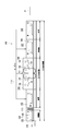
- FIG. 1 shows an overall configuration of a brazing apparatus SB as an embodiment to which the present invention is applied
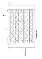
- FIG. 2 shows a front view of a heat exchanger W as an embodiment of a workpiece to be brazed.
- the heat exchanger W as a work to be brazed is used as a radiator or an evaporator in a vehicle, a cooling device or the like, and its structure is the same as that in the case of FIG. That is, the heat exchanger W is composed of aluminum header parts 1 and 1 at both ends and a tube part 2 formed between them, and the tube part 2 is parallel between the header parts 1 and 1.
- the heat exchanger W as a work of the embodiment is generally thinner and lighter than the conventional product as described above, and the header portion 1 actually flows into the header portion 1.
- the inlet pipe and the outlet pipe (not shown) that flow out are connected.
- the header portion 1 has a thickness dimension larger than that of the microtube 3 and the fin 4 constituting the tube portion 2, and has a large heat capacity. Therefore, when similarly heated, the temperature of the header part 1 is difficult to rise, the rate of temperature rise is slow, the temperature of the tube part 2 is likely to rise, and the rate of temperature rise is fast.
- the brazing apparatus SB of FIG. 1 as an embodiment of the brazing apparatus of the present invention is a so-called high-speed brazing furnace, and includes a drying furnace 12 in which a drying chamber 11 is configured, a front chamber 13, It consists of heating furnaces 17 and 18 in which brazing chambers 14 and 16 are respectively configured, a cooling furnace 21 in which a cooling chamber 19 is configured, and a rear chamber 22, which are successively arranged.
- the heat exchanger W placed on and held on the air-permeable tray 23 is transferred to the drying chamber 11, the front chamber 13, and the brazing chambers 14 and 16 by an air-permeable conveying means (mesh belt or roller) 24.
- the cooling chamber 19 and the rear chamber 22 are conveyed in this order.
- the drying chamber 11 is provided with a heater 10, and the processing oil such as isopropylene alcohol (IPA) applied to the heat exchanger W is evaporated by heating the heater 10.
- a metal curtain 26 is provided between the drying chamber 11 and the front chamber 13. Nitrogen gas as an inert gas is introduced into the front chamber 13, the brazing chambers 14, 16 and the cooling chamber 19 through a nitrogen gas introduction pipe 27.
- a near infrared irradiation device 31 as an auxiliary heating means is disposed in the front chamber 13.
- the near-infrared irradiation device 31 includes a near-infrared lamp that generates near-infrared light and a reflecting mirror that collects the near-infrared light generated by the near-infrared lamp toward an irradiation target.
- the heat exchanger (Work)
- the heat capacity of W is large and the header portions 1 and 1 at both ends where the rate of temperature rise is slow are provided so as to irradiate near infrared rays.
- the position of the near infrared irradiation device 31 and / or the irradiation direction of the near infrared radiation is indicated by a broken line in FIG. 3 according to the size and shape of the work (heat exchanger) and the position of the part where the temperature increase rate is slow. It can be changed as shown.
- an electric heater 28 as a main heating means and a furnace fan 29 as a forced convection means are respectively provided as shown in FIG. Therefore, the nitrogen gas heated to a high temperature is forcedly convected into the brazing chambers 14 and 16 by the in-furnace fan 29.
- a hood 32 is provided below the furnace fan 29, and the lower end of the hood 32 is opened above the conveying means 24, and is spaced from the inner wall surfaces of the heating furnaces 17 and 18. The upper end is opened immediately below the in-furnace fan 29 and then narrowed as it gradually goes up.
- the high-temperature nitrogen gas is once blown up by the furnace fan 29, hits the upper walls of the heating furnaces 17 and 18, goes outward, and falls outside the hood 32 (inside the side walls of the heating furnaces 17 and 18). After hitting the bottom wall and heading inward again, it rises, passes through the conveying means 24 and the tray 23, and is blown onto the heat exchanger W from below. Then, after passing through the heat exchanger W, the inside of the hood 32 is further raised and sucked into the furnace fan 29 again (forced convection indicated by an arrow in FIG. 4).
- the brazing operation of the heat exchanger W by the brazing apparatus SB of the embodiment having the above configuration will be described.
- the heat exchanger (work) W is set in a predetermined jig, and the header portions 1 and 1 and the tube portion 2 are arranged in a state as shown in FIG.
- the heat exchanger (workpiece) W in this state is placed on the tray 23 and the tray 23 is placed on the conveying means 24 together.
- the heat exchanger (workpiece) W placed on the tray 23 is transported by the transport means 24, and the surface IPA and processing oil are evaporated in the drying chamber 11 (drying process). Thereafter, the heat exchanger W is transferred to the front chamber 13 through the metal curtain 26, and the atmosphere around the heat exchanger W is changed to a nitrogen gas atmosphere in the process of passing therethrough (pre-process).
- near infrared rays are irradiated from the near infrared irradiation device 31 toward the header portions 1 and 1 of the heat exchanger (work) W as shown in FIG.
- the heat exchanger (workpiece) W is sequentially transferred from the front chamber 13 to the brazing chamber 14 of the heating furnace 17, and forced convection of high-temperature nitrogen gas by the in-furnace fan 29 as described above and direct radiant heat from the electric heater 28. Heated by.
- the heat exchanger (work) W is preheated in the brazing chamber 14, it is then transferred to the brazing chamber 16 of the heating furnace 18, and forced convection of high-temperature nitrogen gas by an in-furnace fan 29 and an electric heater. Further heating by direct radiant heat from 28.
- the header part 1 and the tube part 2 are brazed in the heating process from the preheating in the brazing chamber 14 to the heating in the brazing 16
- the heat exchanger W is moved to the cooling chamber 19. After being transferred and gradually cooled in the nitrogen gas atmosphere in the cooling chamber 19 (cooling step), the final chamber 22 is reached and brazing is completed.
- Control of the brazing device SB that is, the conveying speed of the heat exchanger (workpiece) W by the conveying means 24, the irradiation amount of near infrared rays by the near infrared irradiation device 31 in the front chamber 13, the brazing chambers 14, 16
- the amount of heat generated by the electric heater 28 and the operation of the in-furnace fan 29 are determined by detecting the temperature of the nitrogen gas in each of the chambers 13, 14, 16 and / or the temperature of each part of the heat exchanger (workpiece) W. It is executed by the controller C based on the outputs of the detection devices (thermocouples, etc.) K1 to K3.
- the controller C is constituted by a microcomputer, and a control program for realizing temperature transition of each part of the heat exchanger (work) W described below is incorporated in advance.
- the temperature transition of each part of the heat exchanger (workpiece) W brazed by the brazing apparatus SB will be described with reference to the temperature graph shown in the lower side of FIG.
- the broken line in the graph shown in the lower part of FIG. 1 indicates the temperature of the tube part 2 having a high temperature rising rate in the heat exchanger W
- the solid line indicates the temperature transition of the header part 1 having a low temperature rising rate.
- the header portions 1 and 1 of the heat exchanger (work) W are irradiated with near-infrared rays from the near-infrared irradiation device 31.
- the temperature of 1 (solid line) rises before the temperature of the tube portion 2 (broken line).
- the temperature of the header portion 1 of the heat exchanger (work) W is + 420 ° C. or approximately + 420 ° C.
- the temperature of the tube portion 2 is + 400 ° C. or approximately + 400 ° C. Raise.
- the heat exchanger (workpiece) W is transferred to the brazing chamber 14 and the heating process is started.
- the heat exchanger (work) W is preheated for a predetermined time by forced circulation of high-temperature nitrogen gas by the in-furnace fan 29 and radiant heat from the electric heater 28 as described above.
- the temperature rise since the heat capacity of the tube portion 2 is small, the temperature rises steeply (broken line), but since the header portion 1 has a large heat capacity, the temperature rise is more gradual (solid line).
- the temperature of the header portion 1 since the temperature of the header portion 1 is preliminarily heated by the near infrared rays so that the temperature of the header portion 1 becomes higher than that of the tube portion 2 in the previous step in the front chamber 13, the temperature (dashed line) of the tube portion 2 is the header during the preheating. Although they overtake the temperature of part 1 (solid line), they transition at an approximate temperature.
- the heat exchanger (workpiece) W is then transferred to the brazing 16.
- the heat exchanger (work) W is heated for a predetermined time by forced circulation of high-temperature nitrogen gas by the in-furnace fan 29 and radiant heat from the electric heater 28 as described above. And it heats to +570 degreeC or more +600 degrees C or less finally.
- the temperature of the heat exchanger (workpiece) W is at least + 450 ° C. or more (a temperature in the range of + 440 ° C.
- the temperature difference between the header portion 1 and the tube portion 2 is kept within 5 deg in the embodiment. In the range of + 500 ° C. or higher, the temperature difference between the header portion 1 and the tube portion 2 is kept within 2.5 deg in the embodiment. In the embodiment, the temperature difference between the header part 1 and the tube part 2 is kept within 5 deg when the temperature of the heat exchanger (workpiece) W is + 450 ° C. or more and less than + 500 ° C., and the temperature difference is kept within + 500 ° C. or more.
- the temperature difference between the header part 1 and the tube part 2 is kept within 20 deg at least when the temperature of the heat exchanger (workpiece) W is + 440 ° C. or higher and less than + 500 ° C., and + 500 ° C. or higher. In this range, if the temperature difference is kept within 10 deg, it is considered that the amount of zinc diffusion and distortion can be within the allowable range. Thereby, the header part 1 and the tube part 2 (the microtube 3 and the fin 4) are brazed.
- a pre-process for replacing the atmosphere with nitrogen gas in the front chamber 13 is performed, and then a heating process for preheating and heating the heat exchanger (workpiece) W in the brazing chambers 14 and 16 is performed.
- the near-infrared irradiation device 31 is provided in the front chamber 13 and heat is applied in the previous step. Since the header portion 1, which is a portion where the temperature rising rate of the exchanger (work) W is slow, is heated by the near infrared irradiation device 31, before the heat exchanger (work) W is heated in the brazing chambers 14, 16.
- the temperature of the header portion 1 having a slow temperature increase rate can be raised in advance in the previous step in the front chamber 13.
- the temperature rise of the header portion 1 having a slow temperature rise rate is matched with the temperature rise of the tube portion 2 having a fast temperature rise rate of the heat exchanger (workpiece) W.
- the entire area where the heat exchanger (workpiece) W needs to be brazed as shown by the broken line X in FIG. 5 is uniform. It becomes possible to raise the temperature. Therefore, it is possible to avoid the occurrence of excessive corrosion allowance and a decrease in corrosion resistance when the heat exchanger W composed of the header portion 1 and the tube portion 2 is brazed.
- the temperature (solid line) of the header portion 1 having a slow temperature rise rate is raised first in the previous step in the front chamber 13, and the temperature rise rate is increased in the temperature rise of the portion where the temperature rise rate is slow as in the prior art. Because it does not match the fast parts, it can meet the demand for higher speed. In this case, since the temperature rise by the near-infrared irradiation device 31 in the front chamber 13 is still low (+ 400 ° C. to + 420 ° C.), the adverse effect of oxygen should be ignored even in the previous step of replacing the atmosphere with nitrogen gas. Can do.
- the heating means (implementation) whose heat-resistant temperature is comparatively low as auxiliary heating means It is also possible to employ the example of the near infrared irradiation device 31).
- the near infrared irradiation device 31 irradiates near infrared rays in the previous process and heats the header portion 1 with the slow temperature rise rate of the heat exchanger (workpiece) W, the temperature of the header portion 1 with the slow temperature rise rate is set. It becomes possible to raise the temperature more accurately than the temperature of the tube portion 2 having a high temperature rising rate.
- the temperature of the header portion 1 with a slow temperature rise rate of the heat exchanger (work) W is + 420 ° C. or about + 420 ° C.
- the temperature of the tube portion 2 with a high temperature rise rate is + 400 ° C. or about + 400 ° C.
- the heat exchanger (workpiece) W was transferred to the brazing chamber 14 and shifted to the heating process, so there was no problem with the influence of oxygen in the previous process in the front chamber 13, and the subsequent soldering In the heating process in the attachment chambers 14 and 16, the temperature of the entire heat exchanger (workpiece) W can be quickly and uniformly increased from + 570 ° C. to 600 ° C.
- the header portion 1 having a slow temperature increase rate and the temperature increase rate are
- the temperature difference of the fast tube portion 2 is within 20 deg, preferably within 5 deg
- the temperature of the heat exchanger (workpiece) W is + 500 ° C. or more
- the header portion 1 with a slow temperature rise rate and the tube portion with a fast temperature rise rate Since the temperature difference of 2 is within 10 deg, preferably within 2.5 deg, it is possible to raise the temperature of the entire heat exchanger (workpiece) W more uniformly and to achieve good brazing.
- work) W was heated with the near-infrared irradiation apparatus 31 in the front process of the front chamber 13, Claim 1 and Claim
- the invention of 6 is not limited thereto, and as an auxiliary heating means, for example, an apparatus that sprays high-temperature inert gas (nitrogen gas) on the header portion 1 in a spot manner is also effective.
- the header portion 1 can be heated more locally / intensively.
- the near-infrared irradiation device 31 is provided in the front chamber 13 and the header portion 1 is heated.
- the present invention is not limited thereto, and the near-infrared irradiation device is provided in the drying chamber 11 or the heater 10 is connected to the near-infrared irradiation device ( Auxiliary heating means), the header portion 1 having a slow temperature rise rate of the heat exchanger (work) W is preferentially heated as compared with the tube portion 2 having a high temperature rise rate, and the brazing chamber 14 is transferred from the front chamber 13 to the brazing chamber 14.
- the temperature of the header part 1 with a slow heating rate of the heat exchanger (work) W is + 420 ° C. or approximately + 420 ° C.
- the temperature of the tube part 2 with a fast heating rate is + 400 ° C. or approximately + 400 ° C. It may be made to become.
- the heat exchanger has been described as a workpiece.
- the present invention is not limited thereto, and is effective for all aluminum members manufactured by brazing except for the invention of claim 5.
Landscapes
- Engineering & Computer Science (AREA)
- Mechanical Engineering (AREA)
- Chemical & Material Sciences (AREA)
- Materials Engineering (AREA)
- Tunnel Furnaces (AREA)
Abstract
比較的簡単な構成でワーク各部の昇温の均一化を図り、且つ、高速ろう付けを実現することができるろう付け装置を提供する。本発明のろう付け装置(SB)は、大気を不活性ガスと置換する前室(13)と、熱交換器(ワーク)(W)を加熱するろう付け室(14)、(16)とを順次備え、ろう付け室(14)、(16)内にて熱交換器(ワーク)(W)を構成するアルミニウム部材をろう付けするものであって、前室(13)に設けられ、熱交換器(ワーク)(W)の昇温速度が遅い部位(ヘッダー部(1))を加熱する近赤外線照射装置(補助加熱手段)(31)を備える。
Description
本発明は、ワークを構成するアルミニウム部材をろう付けするろう付け装置、ろう付け方法及びそれにより製造された熱交換器に関するものである。
従来より例えば車両や冷却装置等にて使用される熱交換器は、アルミニウム製のヘッダー部とチューブ部とにより構成されているが、近年の省エネと高効率化の要望からこの種熱交換器においても軽量化と薄肉化の傾向が顕著なものとなっている。また、係る熱交換器(ワーク)をろう付けする場合には、高温とされた不活性ガスをろう付け室内に強制対流させることで、高速ろう付けする方法が開発されている(例えば、特許文献1参照)。
図6は係る従来のろう付け炉100の全体構成を示し、図8はこのろう付け炉100でろう付けされた一般的なこの種熱交換器(ワーク)Wの正面図を示している。ろう付けするワークとしての熱交換器Wは、両端のアルミニウム製ヘッダー部1、1と、それらの間に構成されたチューブ部2とから成る。チューブ部2はヘッダー部1、1間に渡って並列にろう付けされた複数本のアルミニウム製マイクロチューブ3と、これらマイクロチューブ3の間にろう付けされたアルミニウム製のフィン4とから構成されている。
図8において、ワークとしての熱交換器Wは全体としては従来製品よりも薄肉化と軽量化が図られたものであるが、ヘッダー部1はチューブ部2を構成するマイクロチューブ3やフィン4よりも厚み寸法が大きく、熱容量は大きい。従って、同様に加熱した場合、ヘッダー部1の温度は上がり難く、昇温速度は遅くなり、チューブ部2の温度は上がり易く、昇温速度は速くなる。
次に、図6のろう付け炉100は、内部に乾燥室101が構成された乾燥炉102と、前室103と、内部にろう付け室104が構成された加熱炉106と、内部に冷却室107が構成された冷却炉108と、後室109とから構成され、それらが順次連続して配置されており、通気性のトレー111上に載置された熱交換器Wを搬送手段112(メッシュベルトやローラ)により、乾燥室101、前室103、ろう付け室104、冷却室107、後室109の順で搬送する構成とされている。
前記乾燥室101にはヒータ105が設けられ、このヒータ105の加熱により熱交換器Wに塗布されたイソプロピレンアルコール(IPA)等の加工油を蒸発させる。この乾燥室101と前室103の間にはメタルカーテン113が設けられている。この前室103、ろう付け室104及び冷却室107には窒素ガス導入パイプ114により、不活性ガスとしての窒素ガスが導入される。前室103内では大気が窒素ガスと置換されるが、メタルカーテン113は前室103内と乾燥室101とを仕切り、前室103内における大気を窒素ガスとの置換を助ける役割を果たす。
加熱炉106のろう付け室104内には、電気ヒータ116と炉内ファン117が設けられており、この電気ヒータ116で高温に加熱された窒素ガスが炉内ファン117によってろう付け室104内に強制対流される構成とされている。このとき、高温の窒素ガスは炉内ファン117により一旦上に吹き上げられ、外方に向かった後、加熱炉106の内側を降下し、再び内方に向かった後上昇し、トレー111を通過して熱交換器Wに下から吹き付けられ、更に上昇して再び炉内ファン117に吸い込まれる(図6に矢印で示す強制対流)。
トレー111上に載置された熱交換器Wは、搬送手段112により搬送され、乾燥室101で表面のIPAや加工油が蒸発処理される。その後、前室103に移送され、そこを通過する過程で熱交換器Wの周囲は窒素ガス雰囲気とされる。前室103からはろう付け室104に移送され、上述の如き高温窒素ガスの強制対流と電気ヒータ116からの直接の輻射熱によって加熱される。ろう付け室104内では+400℃程で熱交換器Wの表面に腐り代を構成する亜鉛の拡散が始まり、その後、熱交換器Wは+570℃~600℃まで加熱され、ヘッダー部1とチューブ部2(マイクロチューブ3とフィン4)とがろう付けされる。熱交換器Wはその後、冷却室107に移送され、この冷却室107内で窒素ガス雰囲気中における徐冷が行われた後、最終的に後室109に至る。
図7は係る従来のろう付け炉100によってろう付けされる熱交換器W各部の温度推移を示している。図中破線は理想の温度推移、一点鎖線は昇温速度が速い部位(前記チューブ部2)の温度推移、また、実線は昇温速度が遅い部位(前記ヘッダー部1)の温度推移を示している。
前述した如く熱交換器Wをろう付けする場合、熱容量の大きいヘッダー部1は温度が上がり難く、熱容量の小さいチューブ部2は温度が上がり易い。そのため、ろう付け室104にて係る熱交換器(ワーク)Wを加熱した場合には、図7に示すようにヘッダー部1の昇温速度は遅く(実線)、理想の温度推移(破線)より温度が低くなり、チューブ部2の昇温速度は速く(一点鎖線)、理想の温度推移(破線)より高くなる。
このように、ヘッダー部1とチューブ部2の昇温速度は異なるため、従来のろう付け炉100のように高温の窒素ガスを強制対流させて加熱する方式では、熱容量の小さいチューブ部2が先に昇温していき、熱容量の大きいヘッダー部1の昇温は遅れる。そのため、ヘッダー部1とチューブ部2を均一に昇温させることができず、過剰に加熱される箇所P1(図8に示すチューブ部2)には変形や過剰な腐り代の生成が発生し、逆に加熱が不足する箇所P2(図8に示すヘッダー部1)にはろう付け不良や腐り代生成不足が発生してしまう。
特に、薄肉化された熱交換器Wの場合、チューブ部2の昇温速度が速くなると過剰な腐り代が生成されてしまう。また、それを防止するために加熱温度や時間を制限すると、ヘッダー部1において十分な腐り代の生成が行われなくなり、耐食性が悪化してしまう。そのため、この種熱交換器Wのろう付けには、従来よりも高速な加熱と均一な昇温が要求されることになる。
そこで、チューブ部2の温度が所定値に上昇した時点でそこに覆いを置いて昇温を抑制し、ヘッダー部1の昇温速度に合わせる方法が開発されている(例えば、特許文献2参照)。尚、ろう付けには係る高温ガスの強制対流の他に、近赤外線をワーク全体に照射するものもある(例えば、特許文献3、特許文献4参照)。
しかしながら、前記特許文献2のように昇温速度が速いチューブ部2の昇温を遅らせて昇温速度が遅いヘッダー部1に温度上昇を合わせる方法は、高速ろう付けに反することになる。また、前記特許文献3、4のように近赤外線で熱交換器(ワーク)W全体を加熱すれば極めて高速なろう付けが可能となるが、赤外線照射領域は非常に狭いため、ヘッダー部1とチューブ部2の均一な昇温を実現するためには、多数の近赤外線照射装置を高密度で配置しなければならなくなり、コスト的に実現性が乏しくなる。
本発明は、係る従来の技術的課題を解決するために成されたものであり、比較的簡単な構成でワーク各部の昇温の均一化を図り、且つ、高速ろう付けを実現することができるろう付け装置、ろう付け方法及びそれにより製造された熱交換器を提供するものである。
請求項1の発明のろう付け装置は、大気を不活性ガスと置換する前室と、ワークを加熱するろう付け室とを順次備え、ろう付け室内にてワークを構成するアルミニウム部材をろう付けするものであって、前室に設けられ、ワークの昇温速度が遅い部位を加熱する補助加熱手段を備えたことを特徴とする。
請求項2の発明のろう付け装置は、ワークに塗布された加工油を蒸発させる乾燥室と、大気を不活性ガスと置換する前室と、ワークを加熱するろう付け室とを順次備え、ろう付け室内にてワークを構成するアルミニウム部材をろう付けするものであって、乾燥室に設けられ、ワークの昇温速度が遅い部位を優先的に加熱する補助加熱手段を備えたことを特徴とする。
請求項3の発明のろう付け装置は、上記発明において補助加熱手段は、近赤外線を照射することによりワークの昇温速度が遅い部位を加熱することを特徴とする。
請求項4の発明のろう付け装置は、上記各発明においてワークの昇温速度が遅い部位の温度が+420℃又は略+420℃、昇温速度が速い部位の温度が+400℃又は略+400℃となった時点で当該ワークをろう付け室に移送することを特徴とする。
請求項5の発明のろう付け装置は、上記発明においてろう付け室で加熱されるワークの温度が少なくとも+450℃以上+500℃未満の範囲では、昇温速度が遅い部位と昇温速度が速い部位の温度差を20deg以内とし、ワークの温度が+500℃以上の範囲では、昇温速度が遅い部位と昇温速度が速い部位の温度差を10deg以内とすることを特徴とする。
請求項6の発明のろう付け装置は、上記各発明においてワークは、ヘッダー部とチューブ部とより成る熱交換器であり、補助加熱手段はヘッダー部を加熱することを特徴とする。
請求項7の発明のろう付け方法は、前室にて大気を不活性ガスと置換する前工程と、ワークを加熱する加熱工程とを順次実行し、ワークを構成するアルミニウム部材をろう付けする際に、前工程において、ワークの昇温速度が遅い部位を加熱することを特徴とする。
請求項8の発明のろう付け方法は、乾燥室にてワークに塗布された加工油を蒸発させる乾燥工程と、前室にて大気を不活性ガスと置換する前工程と、ワークを加熱する加熱工程とを順次実行し、ワークを構成するアルミニウム部材をろう付けする際に、乾燥工程において、ワークの昇温速度が遅い部位を優先的に加熱することを特徴とする。
請求項9の発明のろう付け方法は、請求項7又は請求項8の発明において前工程において、近赤外線を照射することによりワークの昇温速度が遅い部位を加熱することを特徴とする。
請求項10の発明のろう付け方法は、請求項7乃至請求項8の発明において前工程においてワークの昇温速度が遅い部位の温度が+420℃又は略+420℃、昇温速度が速い部位の温度が+400℃又は略+400℃となった時点で加熱工程に移行することを特徴とする。
請求項11の発明のろう付け方法は、上記発明において加熱工程においてワークの温度が少なくとも+450℃以上+500℃未満の範囲では、昇温速度が遅い部位と昇温速度が速い部位の温度差を20deg以内とし、ワークの温度が+500℃以上の範囲では、昇温速度が遅い部位と昇温速度が速い部位の温度差を10deg以内にすることを特徴とする。
請求項12の発明の熱交換器は、ヘッダー部とチューブ部とより成り、請求項7乃至請求項11のろう付け方法の前工程でヘッダー部を加熱し、又は、乾燥工程でヘッダー部を優先的に加熱することにより製造されたことを特徴とする。
請求項1及び請求項7の発明によれば、前室にて大気を不活性ガスと置換する前工程を行い、次にろう付け室内でワークを加熱する加熱工程を実行してワークを構成するアルミニウム部材をろう付けする場合に、前室に補助加熱手段を設け、前工程においてワークの昇温速度が遅い部位を補助加熱手段により加熱するようにしたので、ろう付け室でワークを加熱する以前に、前室における前工程で予め昇温速度が遅い部位の温度を上げておくことができる。
これにより、ろう付け室内における加熱工程中に、ワークの昇温速度が速い部位の昇温に、昇温速度が遅い部位の昇温を合わせ、ろう付け中にワーク全体を均一に昇温させることができるようになり、請求項6や請求項12の発明の如くヘッダー部とチューブ部とより成る熱交換器をろう付けする際の過剰な腐り代の発生や耐食性の低下を未然に回避することが可能となる。
特に、前室における前工程にて昇温速度が遅い部位の温度を先に上げておくものであり、従来の如く昇温速度が遅い部位の昇温に昇温速度が速い部位を合わせるものでは無いので、高速化の要望も満たすことができる。この場合、前室内での補助加熱手段による温度上昇は依然低いので、大気を不活性ガスに置換する前工程であっても、酸素による悪影響は無視することができると共に、比較的簡単な構成にて実現することができるものである。
請求項2及び請求項8の発明によれば、乾燥室にてワークに塗布された加工油を蒸発させる乾燥工程を行い、次に前室にて大気を不活性ガスと置換する前工程を行い、次にろう付け室内でワークを加熱する加熱工程を実行してワークを構成するアルミニウム部材をろう付けする場合に、乾燥室に補助加熱手段を設け、乾燥工程においてワークの昇温速度が遅い部位を補助加熱手段により優先的に加熱するようにしたので、ろう付け室でワークを加熱する以前に、乾燥室における乾燥工程で予め昇温速度が遅い部位の温度を上げておくことができる。
これにより、ろう付け室内における加熱工程中に、ワークの昇温速度が速い部位の昇温に、昇温速度が遅い部位の昇温を合わせ、ろう付け中にワーク全体を均一に昇温させることができるようになり、請求項6や請求項12の発明の如くヘッダー部とチューブ部とより成る熱交換器をろう付けする際の過剰な腐り代の発生や耐食性の低下を未然に回避することが可能となる。
特に、乾燥室における乾燥工程にて昇温速度が遅い部位を優先的に加熱してその温度を先に上げておくものであり、従来の如く昇温速度が遅い部位の昇温に昇温速度が速い部位を合わせるものでは無いので、高速化の要望も満たすことができる。この場合、乾燥室内での補助加熱手段による温度上昇は依然低いので、大気を不活性ガスに置換する乾燥工程であっても、酸素による悪影響は無視することができると共に、比較的簡単な構成にて実現することができるものである。
また、請求項3及び請求項9の発明の如く前工程や乾燥工程で補助加熱手段により、近赤外線を照射してワークの昇温速度が遅い部位を加熱するようにすれば、昇温速度が遅い部位の温度を速い部位の温度よりも的確に上げておくことが可能となる。
特に、請求項4及び請求項10の発明の如く前工程において、ワークの昇温速度が遅い部位の温度が+420℃又は略+420℃、昇温速度が速い部位の温度が+400℃又は略+400℃となった時点で当該ワークをろう付け室に移送し、加熱工程に移行するようにすれば、前室での前工程や乾燥室での乾燥工程における酸素の影響も問題無く、また、その後のろう付け室における加熱工程では、ワーク全体の温度を+570℃~600℃まで迅速且つ均一に昇温させることが可能となる。
そして、請求項5及び請求項11の発明の如くろう付け室での加熱工程で加熱されるワークの温度が少なくとも+450℃以上+500℃未満の範囲では、昇温速度が遅い部位と昇温速度が速い部位の温度差を20deg以内とし、ワークの温度が+500℃以上の範囲では、昇温速度が遅い部位と昇温速度が速い部位の温度差を10deg以内とすることで、ワーク全体を一層均一に昇温させ、良好なろう付けを実現することが可能となるものである。
以下、本発明の実施の形態について、図1~図5を参照して詳細に説明する。
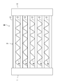
図1は本発明を適用した一実施例としてのろう付け装置SBの全体構成を示し、図2はろう付け対象のワークの実施例としての熱交換器Wの正面図を示している。ろう付けするワークとしての熱交換器Wは、車両や冷却装置等でラジエターやエバポレータとして使用されるものであり、その構造は図8の場合と同様である。即ち、熱交換器Wは、両端のアルミニウム製ヘッダー部1、1と、それらの間に構成されたチューブ部2とから構成されており、チューブ部2はヘッダー部1、1間に渡って並列にろう付けされた複数本のアルミニウム製マイクロチューブ3と、これらマイクロチューブ3の間にろう付けされたアルミニウム製のフィン4とから構成されている。
図2において、実施例のワークとしての熱交換器Wは前述同様に全体としては従来製品よりも薄肉化と軽量化が図られたものであり、ヘッダー部1には実際には冷媒等が流入、流出する図示しない入口管及び出口管が接続されることになる。また、ヘッダー部1はチューブ部2を構成するマイクロチューブ3やフィン4よりも厚み寸法が大きく、熱容量は大きい。従って、同様に加熱した場合、ヘッダー部1の温度は上がり難く、昇温速度は遅くなり、チューブ部2の温度は上がり易く、昇温速度は速くなることとなる。
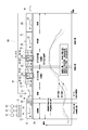
次に、本発明のろう付け装置の実施例としての図1のろう付け装置SBは、所謂高速ろう付け炉であり、内部に乾燥室11が構成された乾燥炉12と、前室13と、内部にろう付け室14、16がそれぞれ構成された加熱炉17、18と、内部に冷却室19が構成された冷却炉21と、後室22とから構成され、それらが順次連続して配置されており、通気性のトレー23上に載置され、保持された熱交換器Wを通気性の搬送手段(メッシュベルトやローラ)24により、乾燥室11、前室13、ろう付け室14、16、冷却室19、後室22の順で搬送する構成とされている。
前記乾燥室11にはヒータ10が設けられており、このヒータ10の加熱により熱交換器Wに塗布されたイソプロピレンアルコール(IPA)等の加工油を蒸発させる。この乾燥室11と前室13の間にはメタルカーテン26が設けられている。この前室13、ろう付け室14、16及び冷却室19には窒素ガス導入パイプ27により、不活性ガスとしての窒素ガスが導入される。
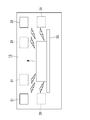
前室13内では大気が窒素ガスと置換されるが、メタルカーテン26は前室13内と乾燥室11とを仕切り、前室13内における大気を窒素ガスとの置換を助ける役割を果たす。また、この前室13内には図3に示すように補助加熱手段としての近赤外線照射装置31が配設されている。この近赤外線照射装置31は、近赤外線を発生する近赤外線ランプとこの近赤外線ランプが発生する近赤外線を照射対象に向けて集光する反射鏡等から構成されており、本発明では熱交換器(ワーク)Wの熱容量が大きく、昇温速度が遅くなる両端のヘッダー部1、1に近赤外線を照射するように設けられている。尚、この近赤外線照射装置31の位置、及び/又は、近赤外線の照射方向は、ワーク(熱交換器)の寸法や形状、昇温速度が遅くなる部位の位置に応じて図3に破線で示すように変更可能とされている。
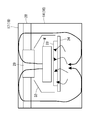
加熱炉17、18のろう付け室14、16内には、図4に示す如く主加熱手段としての電気ヒータ28と強制対流手段としての炉内ファン29がそれぞれ設けられており、この電気ヒータ28により高温に加熱された窒素ガスが炉内ファン29によってろう付け室14、16内にそれぞれ強制対流される構成とされている。このとき、炉内ファン29の下側にはフード32が設けられ、このフード32の下端は搬送手段24の上方にて開口しており、加熱炉17、18の内壁面との間に間隔を存して立ち上がり、徐々に上に行くに従って窄まった後、上端が炉内ファン29の直下にて開口する構造とされている。
これにより、高温の窒素ガスは炉内ファン29により一旦上に吹き上げられ、加熱炉17、18の上壁に当たって外方に向かい、フード32の外側(加熱炉17、18の側壁内側)を降下し、底壁に当たって再び内方に向かった後、上昇して搬送手段24及びトレー23を通過し、熱交換器Wに下から吹き付けられる。そして、熱交換器Wを通過した後、フード32の内側を更に上昇して再び炉内ファン29に吸い込まれることになる(図4に矢印で示す強制対流)。
以上の構成で、次に実施例のろう付け装置SBによる熱交換器Wのろう付け作業について説明する。先ず、熱交換器(ワーク)Wを所定の治具にセットし、ヘッダー部1、1とチューブ部2が図2の如き状態に配置された状態とする。その状態の熱交換器(ワーク)Wをトレー23上に載置し、トレー23ごと搬送手段24上に載せる。
トレー23上に載置された熱交換器(ワーク)Wは、搬送手段24により搬送され、乾燥室11で表面のIPAや加工油が蒸発処理される(乾燥工程)。その後、メタルカーテン26を介して前室13に移送され、そこを通過する過程で熱交換器Wの周囲は窒素ガス雰囲気とされる(前工程)。
この前室13内では、図3に示すように近赤外線照射装置31から熱交換器(ワーク)Wのヘッダー部1、1に向けて近赤外線が照射される。この前室13から熱交換器(ワーク)Wは、加熱炉17のろう付け室14に順次移送され、前述の如き炉内ファン29による高温窒素ガスの強制対流と電気ヒータ28からの直接の輻射熱によって加熱される。
このろう付け室14内で熱交換器(ワーク)Wは予熱された後、次に、加熱炉18のろう付け室16に移送され、同じく炉内ファン29による高温窒素ガスの強制対流と電気ヒータ28からの直接の輻射熱によって更に加熱される。係るろう付け室14における予熱からろう付け16における加熱までの加熱工程でヘッダー部1とチューブ部2(マイクロチューブ3とフィン4)とがろう付けされた後、熱交換器Wは冷却室19に移送され、この冷却室19内で窒素ガス雰囲気中における徐冷が行われた後(冷却工程)、最終的に後室22に至り、ろう付けが終了する。
上記ろう付け装置SBの制御、即ち、搬送手段24による熱交換器(ワーク)Wの搬送速度、前室13内での近赤外線照射装置31による近赤外線の照射量、各ろう付け室14、16内の電気ヒータ28の発熱量及び炉内ファン29の運転等は、各室13、14、16内の窒素ガス温度、及び/又は、熱交換器(ワーク)W各部の温度をそれぞれ検出する温度検出装置(熱電対等)K1~K3の出力に基づき、コントローラCにより実行される。このコントローラCはマイクロコンピュータにより構成され、下記に説明する熱交換器(ワーク)Wの各部の温度推移を実現するための制御プログラムが予め組み込まれている。
次に、図1の下側に示す温度グラフを参照しながら、ろう付け装置SBでろう付けされる熱交換器(ワーク)W各部の温度推移を説明する。図1下に示すグラフ中の破線は熱交換器Wにおいて昇温速度が速いチューブ部2の温度を、実線は昇温速度が遅いヘッダー部1の温度推移をそれぞれ示している。前述したように本発明では前室13内での前工程では、熱交換器(ワーク)Wのヘッダー部1、1に近赤外線照射装置31から近赤外線を照射するので、前室13ではヘッダー部1の温度(実線)がチューブ部2の温度(破線)よりも先に上昇していく。
そして、この前室13内における前工程が終了する時点で、熱交換器(ワーク)Wのヘッダー部1の温度を+420℃又は略+420℃、チューブ部2の温度を+400℃又は略+400℃まで上昇させる。このようにヘッダー部1の温度が+420℃付近、チューブ部2の温度が+400℃付近となった時点で、熱交換器(ワーク)Wをろう付け室14に移送し、加熱工程に入る。
このろう付け室14では前述の如く炉内ファン29による高温の窒素ガスの強制循環と電気ヒータ28からの輻射熱によって熱交換器(ワーク)Wを所定時間予熱する。このとき、チューブ部2は熱容量が小さいので、温度は急峻に上昇するが(破線)、ヘッダー部1は熱容量が大きいため、温度の上昇はそれよりも緩やかなものとなる(実線)。しかしながら、本発明では前室13における前工程で予めヘッダー部1の温度がチューブ部2より高くなるように近赤外線により加熱されているので、予熱の途中でチューブ部2の温度(破線)はヘッダー部1の温度(実線)を追い越すものの、それらは近似した温度で推移する。
ろう付け室14における予熱が終了すると、次に熱交換器(ワーク)Wはろう付け16に移送される。ここで、熱交換器(ワーク)Wを前述の如く炉内ファン29による高温の窒素ガスの強制循環と電気ヒータ28からの輻射熱によって所定時間加熱する。そして、最終的に+570℃以上+600℃以下まで加熱する。更に、係るろう付け室14、16における加熱工程中(冷却工程に入るまでの間)、熱交換器(ワーク)Wの温度が少なくとも+450℃以上(+440℃~+450℃の範囲の温度以上)+500℃未満の範囲では、ヘッダー部1とチューブ部2の温度差を実施例では5deg以内に保つ。また、+500℃以上の範囲では、ヘッダー部1とチューブ部2の温度差を実施例では2.5deg以内に保つものとする。尚、実施例では熱交換器(ワーク)Wの温度が+450℃以上+500℃未満の範囲でヘッダー部1とチューブ部2の温度差を5deg以内に保ち、+500℃以上の範囲では該温度差を2.5deg以内に保つようにしたが、少なくとも熱交換器(ワーク)Wの温度が+440℃以上+500℃未満の範囲でヘッダー部1とチューブ部2の温度差を20deg以内に保ち、+500℃以上の範囲では該温度差を10deg以内に保てば、亜鉛の拡散量と歪みの発生を許容範囲内とすることができると考えられる。これにより、ヘッダー部1とチューブ部2(マイクロチューブ3とフィン4)とをろう付けする。
このように発明によれば、前室13にて大気を窒素ガスと置換する前工程を行い、次にろう付け室14、16内で熱交換器(ワーク)Wを予熱及び加熱する加熱工程を実行して熱交換器(ワーク)Wを構成するアルミニウム製のヘッダー部1とチューブ部2(アルミニウム部材)をろう付けする場合に、前室13に近赤外線照射装置31を設け、前工程において熱交換器(ワーク)Wの昇温速度が遅い部位であるヘッダー部1を近赤外線照射装置31により加熱するようにしたので、ろう付け室14、16で熱交換器(ワーク)Wを加熱する以前に、前室13における前工程で予め昇温速度が遅いヘッダー部1の温度を上げておくことができる。
これにより、ろう付け室14、16内における加熱工程中に、熱交換器(ワーク)Wの昇温速度が速いチューブ部2の昇温に、昇温速度が遅いヘッダー部1の昇温を合わせ、ろう付け中に図5に破線Xで示す熱交換器(ワーク)Wのろう付けが必要な全領域(ヘッダー部1とチューブ部2との接合部からチューブ部2全域に渡る範囲)を均一に昇温させることができるようになる。従って、ヘッダー部1とチューブ部2とより成る熱交換器Wをろう付けする際の過剰な腐り代の発生や耐食性の低下を未然に回避することが可能となる。
特に、前室13における前工程にて昇温速度が遅いヘッダー部1の温度(実線)を先に上げておくものであり、従来の如く昇温速度が遅い部位の昇温に昇温速度が速い部位を合わせるものでは無いので、高速化の要望も満たすことができる。この場合、前室13内での近赤外線照射装置31による温度上昇は依然低い(+400℃~+420℃)ので、大気を窒素ガスに置換する前工程であっても、酸素による悪影響は無視することができる。また、前室13に近赤外線照射装置31を設けるという比較的簡単な構成で実現することができると共に、前室13における加熱であるため、補助加熱手段として耐熱温度が比較的低い加熱手段(実施例の近赤外線照射装置31等)を採用することも可能となる。
また、前工程で近赤外線照射装置31により、近赤外線を照射して熱交換器(ワーク)Wの昇温速度が遅いヘッダー部1を加熱するので、昇温速度が遅いヘッダー部1の温度を昇温速度が速いチューブ部2の温度よりも的確に上げておくことが可能となる。
特に、前工程において、熱交換器(ワーク)Wの昇温速度が遅いヘッダー部1の温度が+420℃又は略+420℃、昇温速度が速いチューブ部2の温度が+400℃又は略+400℃となった時点で熱交換器(ワーク)Wをろう付け室14に移送し、加熱工程に移行するようにしたので、前室13での前工程における酸素の影響も問題無く、また、その後のろう付け室14、16における加熱工程では、熱交換器(ワーク)W全体の温度を+570℃~600℃まで迅速且つ均一に昇温させることが可能となる。
そして、ろう付け室14、16での加熱工程で加熱される熱交換器(ワーク)Wの温度が少なくとも+450℃以上+500℃未満の範囲では、昇温速度が遅いヘッダー部1と昇温速度が速いチューブ部2の温度差を20deg以内、望ましくは5deg以内とし、熱交換器(ワーク)Wの温度が+500℃以上の範囲では、昇温速度が遅いヘッダー部1と昇温速度が速いチューブ部2の温度差を10deg以内、望ましくは2.5deg以内とするので、熱交換器(ワーク)W全体を一層均一に昇温させ、良好なろう付けを実現することが可能となる。
尚、上記実施例では前室13の前工程において、近赤外線照射装置31により熱交換器(ワーク)Wの昇温速度が遅いヘッダー部1を加熱するようにしたが、請求項1及び請求項6の発明ではそれに限らず、補助加熱手段としては例えば高温の不活性ガス(窒素ガス)をヘッダー部1にスポット的に吹き付ける装置でも有効である。但し、実施例のように近赤外線を照射するようにすれば、ヘッダー部1をより局所的/集中的に加熱することが可能となる。
また、実施例では前室13に近赤外線照射装置31を設けてヘッダー部1を加熱したが、それに限らず、乾燥室11に近赤外線照射装置を設け、或いは、ヒータ10を近赤外線照射装置(補助加熱手段)とし、熱交換器(ワーク)Wの昇温速度が遅いヘッダー部1を昇温速度が速いチューブ部2に比して優先的に加熱し、前室13からろう付け室14に移送される時点で、熱交換器(ワーク)Wの昇温速度が遅いヘッダー部1の温度が+420℃又は略+420℃、昇温速度が速いチューブ部2の温度が+400℃又は略+400℃となるようにしてもよい。
更に、実施例では熱交換器をワークとして説明したが、それに限らず、請求項5の発明以外は、ろう付けにて製造されるアルミニウム部材全般に有効である。
SB ろう付け装置
W 熱交換器(ワーク)
1 ヘッダー部(昇温速度が遅い部位)
2 チューブ部(昇温速度が速い部位)
3 マイクロチューブ
4 フィン
13 前室
14、16 ろう付け室
17、18 加熱炉
23 トレー
24 搬送手段
28 電気ヒータ
29 炉内ファン
31 近赤外線照射装置(補助加熱手段)
W 熱交換器(ワーク)
1 ヘッダー部(昇温速度が遅い部位)
2 チューブ部(昇温速度が速い部位)
3 マイクロチューブ
4 フィン
13 前室
14、16 ろう付け室
17、18 加熱炉
23 トレー
24 搬送手段
28 電気ヒータ
29 炉内ファン
31 近赤外線照射装置(補助加熱手段)
Claims (12)
- 大気を不活性ガスと置換する前室と、ワークを加熱するろう付け室とを順次備え、前記ろう付け室内にて前記ワークを構成するアルミニウム部材をろう付けするろう付け装置において、
前記前室に設けられ、前記ワークの昇温速度が遅い部位を加熱する補助加熱手段を備えたことを特徴とするろう付け装置。 - ワークに塗布された加工油を蒸発させる乾燥室と、大気を不活性ガスと置換する前室と、ワークを加熱するろう付け室とを順次備え、前記ろう付け室内にて前記ワークを構成するアルミニウム部材をろう付けするろう付け装置において、
前記乾燥室に設けられ、前記ワークの昇温速度が遅い部位を優先的に加熱する補助加熱手段を備えたことを特徴とするろう付け装置。 - 前記補助加熱手段は、近赤外線を照射することにより前記ワークの昇温速度が遅い部位を加熱することを特徴とする請求項1又は請求項2に記載のろう付け装置。
- 前記ワークの昇温速度が遅い部位の温度が+420℃又は略+420℃、昇温速度が速い部位の温度が+400℃又は略+400℃となった時点で当該ワークを前記ろう付け室に移送することを特徴とする請求項1乃至請求項3のうちの何れかに記載のろう付け装置。
- 前記ろう付け室で加熱される前記ワークの温度が少なくとも+450℃以上+500℃未満の範囲では、前記昇温速度が遅い部位と前記昇温速度が速い部位の温度差を20deg以内とし、前記ワークの温度が+500℃以上の範囲では、前記昇温速度が遅い部位と前記昇温速度が速い部位の温度差を10deg以内とすることを特徴とする請求項4に記載のろう付け装置。
- 前記ワークは、ヘッダー部とチューブ部とより成る熱交換器であり、前記補助加熱手段は前記ヘッダー部を加熱することを特徴とする請求項1乃至請求項5のうちの何れかに記載のろう付け装置。
- 前室にて大気を不活性ガスと置換する前工程と、ワークを加熱する加熱工程とを順次実行し、前記ワークを構成するアルミニウム部材をろう付けするろう付け方法において、
前記前工程において、前記ワークの昇温速度が遅い部位を加熱することを特徴とするろう付け方法。 - 乾燥室にてワークに塗布された加工油を蒸発させる乾燥工程と、前室にて大気を不活性ガスと置換する前工程と、ワークを加熱する加熱工程とを順次実行し、前記ワークを構成するアルミニウム部材をろう付けするろう付け方法において、
前記乾燥工程において、前記ワークの昇温速度が遅い部位を優先的に加熱することを特徴とするろう付け方法。 - 前記前工程において、近赤外線を照射することにより前記ワークの昇温速度が遅い部位を加熱することを特徴とする請求項7又は請求項8に記載のろう付け方法。
- 前記前工程において前記ワークの昇温速度が遅い部位の温度が+420℃又は略+420℃、昇温速度が速い部位の温度が+400℃又は略+400℃となった時点で前記加熱工程に移行することを特徴とする請求項7乃至請求項9に記載のろう付け方法。
- 前記加熱工程において前記ワークの温度が少なくとも+450℃以上+500℃未満の範囲では、前記昇温速度が遅い部位と前記昇温速度が速い部位の温度差を20deg以内とし、前記ワークの温度が+500℃以上の範囲では、前記昇温速度が遅い部位と前記昇温速度が速い部位の温度差を10deg以内にすることを特徴とする請求項10に記載のろう付け方法。
- ヘッダー部とチューブ部とより成り、請求項7乃至請求項11のうちの何れかに記載のろう付け方法の前記前工程で前記ヘッダー部を加熱し、又は、前記乾燥工程で前記ヘッダー部を優先的に加熱することにより製造されたことを特徴とする熱交換器。
Applications Claiming Priority (2)
| Application Number | Priority Date | Filing Date | Title |
|---|---|---|---|
| JP2013-064433 | 2013-03-26 | ||
| JP2013064433A JP6073724B2 (ja) | 2013-03-26 | 2013-03-26 | ろう付け装置及びろう付け方法 |
Publications (1)
| Publication Number | Publication Date |
|---|---|
| WO2014156845A1 true WO2014156845A1 (ja) | 2014-10-02 |
Family
ID=51623825
Family Applications (1)
| Application Number | Title | Priority Date | Filing Date |
|---|---|---|---|
| PCT/JP2014/057362 Ceased WO2014156845A1 (ja) | 2013-03-26 | 2014-03-18 | ろう付け装置、ろう付け方法及び熱交換器 |
Country Status (2)
| Country | Link |
|---|---|
| JP (1) | JP6073724B2 (ja) |
| WO (1) | WO2014156845A1 (ja) |
Cited By (1)
| Publication number | Priority date | Publication date | Assignee | Title |
|---|---|---|---|---|
| CN105290633A (zh) * | 2015-12-04 | 2016-02-03 | 浙江海悦自动化机械股份有限公司 | 一种汇流排的熔焊方法 |
Families Citing this family (3)
| Publication number | Priority date | Publication date | Assignee | Title |
|---|---|---|---|---|
| JP2016083699A (ja) * | 2014-10-28 | 2016-05-19 | 株式会社Uacj | ろう付炉及びアルミニウム材のろう付方法 |
| KR101794598B1 (ko) * | 2016-10-18 | 2017-12-01 | 주식회사 포스코 | 스토퍼 |
| JP2019211227A (ja) * | 2018-05-31 | 2019-12-12 | 学校法人早稲田大学 | 温度計測システム、加熱炉及び加熱炉内におけるワーク温度取得方法 |
Citations (3)
| Publication number | Priority date | Publication date | Assignee | Title |
|---|---|---|---|---|
| US20040056068A1 (en) * | 2002-09-19 | 2004-03-25 | Alan Rae | Reflow soldering apparatus and method for selective infrared heating |
| US20070164088A1 (en) * | 2006-01-18 | 2007-07-19 | Kam Dianatkhah | Brazing process for stainless steel heat exchangers |
| JP2012159218A (ja) * | 2011-01-31 | 2012-08-23 | Denso Corp | ろう付け装置 |
Family Cites Families (1)
| Publication number | Priority date | Publication date | Assignee | Title |
|---|---|---|---|---|
| JP2003080366A (ja) * | 2001-07-05 | 2003-03-18 | Denso Corp | 熱交換器の製造方法 |
-
2013
- 2013-03-26 JP JP2013064433A patent/JP6073724B2/ja active Active
-
2014
- 2014-03-18 WO PCT/JP2014/057362 patent/WO2014156845A1/ja not_active Ceased
Patent Citations (3)
| Publication number | Priority date | Publication date | Assignee | Title |
|---|---|---|---|---|
| US20040056068A1 (en) * | 2002-09-19 | 2004-03-25 | Alan Rae | Reflow soldering apparatus and method for selective infrared heating |
| US20070164088A1 (en) * | 2006-01-18 | 2007-07-19 | Kam Dianatkhah | Brazing process for stainless steel heat exchangers |
| JP2012159218A (ja) * | 2011-01-31 | 2012-08-23 | Denso Corp | ろう付け装置 |
Cited By (1)
| Publication number | Priority date | Publication date | Assignee | Title |
|---|---|---|---|---|
| CN105290633A (zh) * | 2015-12-04 | 2016-02-03 | 浙江海悦自动化机械股份有限公司 | 一种汇流排的熔焊方法 |
Also Published As
| Publication number | Publication date |
|---|---|
| JP2014188535A (ja) | 2014-10-06 |
| JP6073724B2 (ja) | 2017-02-01 |
Similar Documents
| Publication | Publication Date | Title |
|---|---|---|
| JP6073724B2 (ja) | ろう付け装置及びろう付け方法 | |
| US5322209A (en) | Aluminum heat exchanger brazing method and apparatus | |
| JP5343988B2 (ja) | ろう付け装置 | |
| JP5795560B2 (ja) | ワークを熱加工する炉 | |
| JP4480231B2 (ja) | 金属製ワークピースのコンベクション式ろう付け方法およびその装置 | |
| CN105772886B (zh) | 一种通孔回流焊装置及其控制方法 | |
| KR20090005488A (ko) | 리플로우 장치 및 방법 | |
| CN112118922A (zh) | 用于热成型的板材的传导预热 | |
| JP2004141944A (ja) | 雰囲気炉及びその加熱方法 | |
| JP6502910B2 (ja) | リフロー装置 | |
| JP5197859B1 (ja) | 熱間プレス用の鋼板の熱処理方法 | |
| JP6908485B2 (ja) | 連続窒化処理炉および連続窒化処理方法 | |
| CN101676064B (zh) | 用于制造和装配蒸汽发生器的过热器蛇形管的方法 | |
| JP2018145450A (ja) | 熱処理された金属板の製造方法 | |
| JP6063316B2 (ja) | ろう付け装置 | |
| JP2010042439A (ja) | 対流熱兼輻射熱併用式ろう付け手法とろう付け炉 | |
| US10619925B2 (en) | Heating device for hot stamping | |
| JP2002164647A (ja) | リフローはんだ付け装置 | |
| CN120311016B (zh) | 压铸件淬火变形的控制方法及制备方法 | |
| JP3683166B2 (ja) | 基板の熱処理方法及びそれに用いる連続式熱処理炉 | |
| US4501387A (en) | Method for brazing heat exchanger cores by blowing hot gases | |
| JPWO2007077727A1 (ja) | リフロー装置 | |
| JP2025120971A (ja) | 焼成方法及び焼成装置 | |
| JP2008196756A (ja) | 加熱炉 | |
| JP4445476B2 (ja) | 熱処理炉及び太陽電池セル |
Legal Events
| Date | Code | Title | Description |
|---|---|---|---|
| 121 | Ep: the epo has been informed by wipo that ep was designated in this application |
Ref document number: 14775506 Country of ref document: EP Kind code of ref document: A1 |
|
| NENP | Non-entry into the national phase |
Ref country code: DE |
|
| 122 | Ep: pct application non-entry in european phase |
Ref document number: 14775506 Country of ref document: EP Kind code of ref document: A1 |