WO2014156800A1 - レンズ加工制御装置、レンズ加工制御プログラム、レンズ形状判定方法および眼鏡レンズの製造方法 - Google Patents
レンズ加工制御装置、レンズ加工制御プログラム、レンズ形状判定方法および眼鏡レンズの製造方法 Download PDFInfo
- Publication number
- WO2014156800A1 WO2014156800A1 PCT/JP2014/057237 JP2014057237W WO2014156800A1 WO 2014156800 A1 WO2014156800 A1 WO 2014156800A1 JP 2014057237 W JP2014057237 W JP 2014057237W WO 2014156800 A1 WO2014156800 A1 WO 2014156800A1
- Authority
- WO
- WIPO (PCT)
- Prior art keywords
- shape
- lens
- processing
- theoretical
- bevel
- Prior art date
- Legal status (The legal status is an assumption and is not a legal conclusion. Google has not performed a legal analysis and makes no representation as to the accuracy of the status listed.)
- Ceased
Links
Images





Classifications
-
- B—PERFORMING OPERATIONS; TRANSPORTING
- B24—GRINDING; POLISHING
- B24B—MACHINES, DEVICES, OR PROCESSES FOR GRINDING OR POLISHING; DRESSING OR CONDITIONING OF ABRADING SURFACES; FEEDING OF GRINDING, POLISHING, OR LAPPING AGENTS
- B24B9/00—Machines or devices designed for grinding edges or bevels on work or for removing burrs; Accessories therefor
- B24B9/02—Machines or devices designed for grinding edges or bevels on work or for removing burrs; Accessories therefor characterised by a special design with respect to properties of materials specific to articles to be ground
- B24B9/06—Machines or devices designed for grinding edges or bevels on work or for removing burrs; Accessories therefor characterised by a special design with respect to properties of materials specific to articles to be ground of non-metallic inorganic material, e.g. stone, ceramics, porcelain
- B24B9/08—Machines or devices designed for grinding edges or bevels on work or for removing burrs; Accessories therefor characterised by a special design with respect to properties of materials specific to articles to be ground of non-metallic inorganic material, e.g. stone, ceramics, porcelain of glass
- B24B9/14—Machines or devices designed for grinding edges or bevels on work or for removing burrs; Accessories therefor characterised by a special design with respect to properties of materials specific to articles to be ground of non-metallic inorganic material, e.g. stone, ceramics, porcelain of glass of optical work, e.g. lenses, prisms
Definitions
- the present invention relates to a lens processing control device, a lens processing control program, a lens shape determination method, and a spectacle lens manufacturing method used when performing bevel processing of spectacle lenses.
- the spectacle lens to be fitted into the spectacle frame is formed through a lens shape process on the unprocessed lens.
- the lens shape processing is a processing for making the lens peripheral portion into a shape that can be put into a spectacle frame, and is generally performed using a lens processing machine called a target lens processing machine.
- the processed spectacle lens is formed with a bevel having a shape corresponding to the frame shape of the spectacle frame to be framed on the periphery of the lens.
- the bead processing for forming the bevel is referred to as “bevel processing”.
- the lens shape measuring instrument used in that case is configured to measure the shape of the lens periphery by moving a measuring element called a stylus in contact with the lens periphery while moving in the lens circumferential direction. Is known (see, for example, Patent Document 1).
- Machining tool interference that occurs during beveling is as follows.
- the influence of the target lens shape to be processed, the curve of the lens to be processed, the diameter of the processing tool (grinding / cutting tool) used for processing, the bevel shape to be formed, etc. Therefore, during processing, the processing tool and the processed portion of the lens may interfere with each other at a point other than the theoretical cutting point. This is called “machining tool interference”.
- machining tool interference occurs, parts other than the theoretical cutting point are also machined, so that the shape of the bevel to be formed becomes thin or distorted. Therefore, the processing tool interference becomes a factor that the lens peripheral portion is not processed according to the desired shape after the beveling.
- the trajectory in the circumferential direction of the bevel tip (hereinafter referred to as “bevel tip trajectory”) must be changed in the Z-axis direction (lens optical axis direction).
- the Z-axis direction (lens optical axis direction)
- a general spectacle lens has a curve corresponding to the prescription content, and the bevel tip trajectory has a change in the Z-axis direction in most cases, so it is difficult to avoid the occurrence of the processing tool interference. It is.
- a defect in a lens processing machine is a defect that affects the result of the beveling process.
- at least one of the raw lens rotation axis or the processing tool rotation axis is in a position that is shifted from the original position due to misadjustment or a time-dependent reason, or the raw lens is blocked.
- the origin position in the rotation direction ( ⁇ direction) is shifted from the original position due to work mistakes, etc., and the processing tool used with the lens processing machine There is a problem that there is a setting error in the tool diameter value.
- the shape of the lens peripheral edge portion after the beveling using the lens processing machine is different from the desired shape. That is, the trouble in the lens processing machine becomes a factor that the lens peripheral portion is not processed as desired after the beveling. Note that a defect in the lens processing machine can be solved by feeding back to the lens processing machine a content that specifically identifies the defect.
- the lens peripheral portion of the spectacle lens there are two factors that cause the lens peripheral portion of the spectacle lens not to have a desired shape, that is, due to interference with the processing tool and due to a malfunction of the lens processing machine.
- these two factors are not separated. Therefore, for example, even if the result of determination that the lens periphery is not the desired shape is obtained by shape measurement, it is not known whether the result is due to the above two factors, that is, unavoidable or resolvable. Even if feedback to the processing machine is performed, a beveling result as a desired shape is not always obtained. That is, in the conventional shape measurement, a series of processes from the shape measurement to the pass / fail determination cannot always be performed accurately.
- the lens processing machine may be calibrated at a predetermined timing.
- a flat lens that does not cause processing tool interference or a predetermined lens that can be handled equivalently is used as a test lens, and the test lens is beveled with a lens processing machine at a preset periodic timing.
- Feedback is performed to solve the problem in the lens processing machine.
- An object of the present invention is to provide a lens processing control device, a lens processing control program, a lens shape determination method, and a spectacle lens manufacturing method.
- the inventor of the present application examined interference between a processing tool used for beveling and a processed portion of a lens, which causes thinning or distortion of the bevel shape. Interference is inevitable when considering lens curves etc., but the amount of interference at that time is known at the stage of beveling such as the shape and trajectory of the processing tool, the curve of the lens to be processed and the shape of the target lens It is possible to specify based on the information.
- the inventor of the present application obtains the predicted finish shape of the bevel cross-section considering the amount of interference of the processing tool, obtains the contact state of the probe of the lens shape measuring instrument with respect to the bevel of the spectacle lens having the predicted finish shape,
- the shape measurement result that would be obtained by the lens shape measuring instrument when the contact mode is reflected is the theoretical shape of the peripheral edge of the spectacle lens after beveling (hereinafter simply referred to as “theoretical shape”), and the theoretical shape.
- a predicted shape specifying means for obtaining a predicted finish shape of a bevel cross section in consideration of a processing tool interference amount when performing a bevel processing on an unprocessed spectacle lens, and a spectacle lens having the predicted finish shape Contact state specifying means for obtaining the contact state of the probe of the lens shape measuring instrument with respect to the bevel, and the shape measurement result that would be obtained by the lens shape measuring device when reflecting the contact state, Comparing the theoretical shape with the theoretical shape specifying means for the theoretical shape of the lens periphery and the actual shape obtained by the lens shape measuring instrument for the spectacle lens periphery after the bevel processing, and based on the comparison result,
- a lens processing control device comprising: a shape comparison unit that performs quality determination on a shape.
- the predicted shape specifying means includes the measurement unit for each measurement point set in a plurality of locations in the circumferential direction of the spectacle lens. A predicted finish shape is obtained, and the contact state specifying means obtains the contact state of the probe with respect to the bevel of the predicted finish shape for each measurement point.
- a predicted shape specifying means for obtaining a predicted finish shape of a bevel cross section in consideration of a processing tool interference amount when performing bevel processing on an unprocessed spectacle lens;
- Contact state specifying means for obtaining a contact state of a probe of a lens shape measuring instrument with respect to a bevel of a spectacle lens, and a shape measurement result that would be obtained by the lens shape measuring device when the contact state is reflected
- the theoretical shape specifying means for the theoretical shape of the spectacle lens periphery after the comparison, the actual shape actually obtained by the lens shape measuring instrument for the spectacle lens periphery after the beveling is compared with the theoretical shape, and based on the comparison result
- the lens processing control program is made to function as a shape comparison means for performing pass / fail judgment on the measured shape.
- the computer performs beveling of the spectacle lens that obtains the measured shape based on a comparison result between the measured shape and the theoretical shape.
- the lens processing machine is made to function as a correction instructing unit that causes the processing amount to be corrected by an amount corresponding to the amount of difference between the measured shape and the theoretical shape.
- a predicted shape specifying step for obtaining a predicted finish shape of a bevel cross section in consideration of a processing tool interference amount when performing a bevel processing on an unprocessed spectacle lens, and a spectacle lens having the predicted finish shape
- a contact mode specifying step for obtaining a contact mode of the probe of the lens shape measuring instrument with respect to the bevel, and a shape measurement result that would be obtained by the lens shape measuring instrument when reflecting the contact mode
- the theoretical shape specifying step for setting the theoretical shape of the lens periphery, and the actual shape actually obtained by the lens shape measuring device for the peripheral edge of the spectacle lens after beveling are compared with the theoretical shape, and the comparison result is compared with the actual shape.
- a lens shape determination method comprising: a shape comparison step used for quality determination.
- the bevel processing of the spectacle lens that obtained the measured shape is performed based on the comparison result between the measured shape and the theoretical shape using the lens shape determination method according to the seventh aspect.
- a spectacle lens manufacturing method comprising: a processing amount correction step of causing a performed lens processing machine to perform a processing amount correction corresponding to an amount of difference between the measured shape and the theoretical shape.
- FIG. 1 is a schematic diagram showing an overall configuration example of a spectacle lens supply system including a lens processing control device according to the present invention.
- an eyeglass lens supply system exemplified in the present embodiment is distributed and arranged in a spectacle store 100 that is an eyeglass lens ordering side and a lens manufacturer factory 200 that is a lens processing side. It is configured. In the example shown in the figure, only one spectacle store 100 is shown, but actually, a plurality of spectacle stores 100 may exist for one factory 200.
- the spectacle store 100 is provided with an online terminal computer 101 and a spectacle frame measuring machine 102 that measures the frame shape of the spectacle frame and outputs frame shape data.
- the terminal computer 101 includes an input device such as a keyboard and a mouse, and a display device such as a liquid crystal panel, and is connected to the factory 200 side via the public communication network 300 to exchange data with the factory 200 side. Configured to do.
- the spectacle frame measuring machine 102 detects a cylindrical coordinate value of the shape of the frame groove in a three-dimensional manner by bringing a measuring element into contact with the frame grooves of the left and right frames of the spectacle frame and rotating the measuring element about a predetermined point. Then, the frame shape of the spectacle frame is measured. The measurement result is output to the terminal computer 101 as frame shape data of the spectacle frame.
- the spectacle lens prescription value and the like desired by the customer are input by the terminal computer 101 and the frame shape data of the spectacle frame desired by the customer.
- the terminal computer 101 transfers these contents online to the main frame 201 on the factory 200 side via the public communication network 300. ing.
- a main frame 201 connected to the terminal computer 101 on the spectacle store 100 side via the public communication line network 300 is installed on the factory 200 side.
- the main frame 201 has a function as a computer device that executes a spectacle lens processing design program, a bevel processing design program, and the like, and a lens including a bevel shape based on input data from the terminal computer 101 on the spectacle store 100 side. It is comprised so that a shape may be calculated.
- the main frame 201 is connected to a plurality of terminal computers 210, 220, 230, 240, 250 installed on the factory 200 side via the LAN 202 in addition to the public communication network 300, and calculates the lens shape. The result is sent to each terminal computer 210, 220, 230, 240, 250.
- a rubbing machine (curve generator) 211 and a sanding grinder 212 are connected to the terminal computer 210. Then, the terminal computer 210 controls the rough rubbing machine 211 and the sand grinder 212 while following the calculation result sent from the main frame 201 to finish the curved surface of the back surface (rear surface) of the front surface processed lens.
- a lens meter 221 and a wall thickness gauge 222 are connected to the terminal computer 220. Then, the terminal computer 220 compares the measurement value obtained by the lens meter 221 and the thickness gauge 222 with the calculation result sent from the main frame 201, and the curved surface finishing of the lens back surface (rear surface) is completed. The acceptance inspection of the spectacle lens is performed, and a mark (three-point mark) indicating the optical center is attached to the passing lens.
- a marker 231 and an image processor 232 are connected to the terminal computer 230. Then, the terminal computer 230 controls the marker 231 and the image processor 232 while following the calculation result sent from the main frame 201 to block (hold) the lens when performing edge trimming and beveling of the spectacle lens. ) Determine the blocking position to be performed, and add a blocking position mark. According to this blocking position mark, a jig for blocking is fixed to the lens.
- the terminal computer 240 is connected to an NC control lens processing machine 241 and a chuck interlock 242. Then, the terminal computer 240 controls the lens processing machine 241 while following the calculation result sent from the main frame 201, and causes the lens processing machine 241 to process the eyeglass lens.
- the target lens shape processing includes “edging processing” in which an unprocessed lens is ground in accordance with the shape of the spectacle frame, and “beveling processing” in which a bevel is provided on the edged lens.
- the lens processing machine 241 that performs the target processing including the bevel processing corresponds to the “lens processing machine” in the present invention.
- the terminal computer 250 is connected to a shape measuring instrument 251 for measuring the shape of the lens peripheral edge after beveling.
- the shape measuring device 251 that performs such shape measurement corresponds to the “lens shape measuring device” in the present invention. Then, the terminal computer 250 controls the shape measuring instrument 251 to cause the shape measuring instrument 251 to measure the circumference and shape of the beveled spectacle lens, and the calculation result sent from the main frame 201 Compared to, the quality of the beveling is judged.
- the main frame 201 calculates the spectacle lens shape including the bevel shape based on the input data from the terminal computer 101 on the spectacle store 100 side, and each terminal while following the calculation result.
- the computers 210, 220, 230, 240, 250 control the lens processing machine 241, the shape measuring device 251, and the like, so that the spectacles that have been beveled and the lens peripheral shape and the bevel shape match the shape of the spectacle frame frame. Lenses are manufactured.
- the lens processing machine 241 it is necessary for the lens processing machine 241 to perform eyeglass processing of the spectacle lens mainly in the main frame 201, the terminal computer 240, and the terminal computer 250. Control processing is performed. That is, the main frame 201, the terminal computer 240, and the terminal computer 250 have a function as a “lens processing control device” according to the present invention.
- the “lens shape determination method” according to the present invention is mainly implemented in the main frame 201 and the terminal computer 250, as will be described in detail later.
- the “eyeglasses” according to the present invention is mainly configured by the main frame 201, the terminal computer 240, the lens processing machine 241, the terminal computer 250, and the shape measuring instrument 251.
- the “lens manufacturing method” is performed.
- lens processing machine 241 that performs edge-grinding and beveling of a spectacle lens will be described.
- the lens processing machine 241 has a rotating grindstone for grinding that is controlled to move in the Y-axis direction (perpendicular to the spindle axis direction) and performs edge-grinding and beveling of the spectacle lens, and a block jig for fixing the lens.
- NC control capable of at least three-axis control: tool rotation angle control (spindle axis rotation direction) and Z-axis control that performs beveling by moving the grindstone or spectacle lens in the Z-axis direction (spindle axis direction) This is a grinding device.
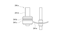
- FIG. 2 is an explanatory view showing an example of a rotating grindstone tool used by the lens processing machine 241 for beveling.
- the rotary grindstone tool 241a shown in the figure includes a grindstone portion 241c having a bevel groove 241b formed so as to correspond to a beveling slope on the front side of the lens and a beveling slope on the rear side of the lens. And it is comprised so that a bevel process may be performed with respect to the perimeter of the spectacle lens 241e by moving along the lens periphery, rotating around the rotating shaft 241d.
- the trajectory when moving such a rotating grindstone tool 241a along the lens periphery is calculated by the main frame 201.
- the main frame 201 performs a bevel machining design calculation by starting the bevel machining design program. That is, based on the input data from the terminal computer 101 on the spectacle store 100 side, a design operation for three-dimensional beveling is performed to calculate the final three-dimensional bevel tip shape, and the calculated three-dimensional bevel tip shape. Based on the above, three-dimensional machining trajectory data on the machining coordinates when grinding with the rotary grindstone tool 241a having a predetermined radius is calculated.
- the three-dimensional machining trajectory data calculated by the main frame 201 corresponds to the three-dimensional bevel tip shape, in most cases it has a displacement in the Z-axis direction. Therefore, in the lens processing machine 241, when the beveling is performed according to the three-dimensional processing trajectory data from the main frame 201, the bevel groove of the rotary grindstone tool 241a is three-dimensionally formed on the bevel processing slope assumed on the data. Interference may occur and the bevel apex that is actually processed becomes smaller than expected.
- the lens processing machine 241 even if the beveling is performed according to the three-dimensional processing trajectory data from the main frame 201, the lens processing machine 241 is formed due to the interference with the rotating grindstone tool 241a that is displaced in the Z-axis direction during the beveling.
- the bevel shape may be thinned, distorted, or the like, and the bevel may not be located at the position assumed during the beveling process. It can be said that the occurrence of such tool interference is inevitable in consideration of a lens curve and the like.
- shape measuring instrument Next, the shape measuring instrument 251 that measures the circumference and shape of the beveled lens will be described.
- the shape measuring instrument 251 includes a stylus as a probe for measuring the bevel apex, and is configured to measure the circumference and shape of the beveled spectacle lens using the stylus.
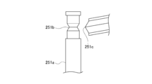
- FIG. 3 is an explanatory diagram showing an example of a stylus included in the shape measuring instrument 251.
- the stylus 251a shown in the figure has a contact portion 251b provided with a V-shaped groove that matches a predetermined bevel shape along the circumference, and this contact portion 251b is a bevel of a beveled spectacle lens. It is comprised so that it may contact
- the shape measuring instrument 251 performs measurement while moving the stylus 251a in the circumferential direction of the lens in a state where the stylus 251a is in contact with the bevel 251c of the spectacle lens. More specifically, the stylus 251a is moved while rolling, and the three-dimensional cylindrical coordinate value of each bevel 251c at that time is measured. That is, the movement distance, rotation angle, and vertical movement distance of the stylus 251a in the lens circumferential direction are measured. Then, from the three-dimensional cylindrical coordinate value of the bevel 251c measured in this way, the passing trajectory of the virtual bevel apex predetermined by the stylus is recognized, and the circumference and three-dimensional shape of the passing trajectory are calculated. Is sent to the terminal computer 250 as the peripheral length and shape of the beveled spectacle lens.
- FIG. 4 is a block diagram illustrating a functional configuration example of the main frame 201 and the terminal computers 240 and 250.
- the main frame 201 has functions as data acquisition means 201a, predicted shape specifying means 201b, contact mode specifying means 201c, theoretical shape specifying means 201d, and theoretical shape notifying means 201e.
- the terminal computer 250 has functions as a theoretical shape acquisition unit 250a, an actual measurement shape acquisition unit 250b, a shape comparison unit 250c, and a determination result output unit 250d.
- the terminal computer 240 has functions as a determination result acquisition unit 240a and a correction instruction unit 240b.
- each of these means 201a to 201e, 250a to 250d, and 240a to 240b will be described in order.
- the data acquisition unit 201a acquires data necessary for specifying a theoretical shape to be described later.
- data to be acquired for example, data (lens curve data or the like) for specifying the lens shape after performing the edge processing and the bevel processing, the shape data of the rotating grindstone tool 241a of the lens processing machine 241, the rotating grindstone thereof Examples thereof include three-dimensional machining locus data on machining coordinates when grinding with the tool 241a, shape data of the stylus 251a of the shape measuring instrument 251, and the like.
- These data may be acquired by accessing the terminal computer 101 on the spectacle store 100 side, the lens processing machine 241 on the factory 200 side, the shape measuring instrument 251 and the like, or these data may be acquired on the factory 200 side. It may be performed by accessing a database (not shown) provided for collective management.
- the predicted shape specifying unit 201b is inevitable to generate tool interference during the beveling with the lens processing machine 241, and therefore, when performing the beveling based on the data acquired by the data acquiring unit 201a.
- the predicted finish shape of the bevel cross section considering the amount of machining tool interference is obtained. That is, the shape of the bevel cross section after thinning, distortion, or the like due to tool interference is obtained as a predicted finished shape. Details of how to obtain the predicted finished shape will be described later.
- the contact mode specifying unit 201c is a shape for measuring the bevel circumference of the spectacle lens with respect to the bevel of the spectacle lens having the predicted finished shape obtained by the predicted shape specifying unit 201b based on the data acquired by the data acquiring unit 201a. It is determined how the stylus 251a of the measuring instrument 251 contacts. That is, the contact mode of the stylus 251a with the bevel of the predicted finished shape is obtained. The method for obtaining the contact mode of the stylus 251a will be described later in detail.
- the theoretical shape specifying unit 201d is obtained by the shape measuring instrument 251 when the contact state of the stylus 251a obtained by the contact state specifying unit 201c is reflected on the spectacle lens having the finished predicted shape obtained by the predicted shape specifying unit 201b.
- the shape measurement result will be specified, and the shape measurement result is set as the theoretical three-dimensional shape (that is, the theoretical shape) of the peripheral edge of the spectacle lens after the beveling process. More specifically, based on the trajectory of the stylus 251a when the stylus 251a is moved in the lens circumferential direction while the stylus 251a is in contact with the bevel of the predicted finish shape, the theoretical shape of the spectacle lens having the predicted finish shape is shown. Try to ask.
- this theoretical shape is a shape that corresponds to the predicted finish of the bevel considering the amount of interference of the processing tool, the design lens periphery calculated without considering the amount of interference of the processing tool by executing the bevel processing design program
- the shape (hereinafter simply referred to as “design shape”) is different. The method for specifying the theoretical shape will be described later in detail.
- the theoretical shape notifying means 201e notifies at least the terminal computer 250 about the theoretical shape specified by the theoretical shape specifying means 201d.
- the theoretical shape acquisition unit 250a acquires the theoretical shape notified from the theoretical shape notification unit 201e of the main frame 201.
- the actually measured shape obtaining unit 250b converts the three-dimensional shape (hereinafter simply referred to as “actually measured shape”) as a result of the measurement. Obtained from the measuring device 251.
- the shape comparison means 250c compares the theoretical shape acquired by the theoretical shape acquisition means 250a with the actual measurement shape acquired by the actual measurement shape acquisition means 250b, and determines pass / fail of the beveled spectacle lens. In other words, the quality of the actually measured shape is determined for the spectacle lens in which the actually measured shape is measured by comparison with the theoretical shape, not the design shape. Details of the comparison between the theoretical shape and the actually measured shape and the quality determination based on the comparison result will be described later.
- the determination result output means 250d outputs the result of the quality determination by the shape comparison means 250c to, for example, the terminal computer 240.
- the main frame 201 may be added to the output destination of the pass / fail judgment result.
- the determination result acquisition unit 240a acquires the pass / fail determination result output from the determination result output unit 250d of the terminal computer 250.
- the correction instructing unit 240b is a lens processing machine that performs beveling of the spectacle lens that has obtained the actually measured shape based on the pass / fail determination result acquired by the determination result acquiring unit 240a (that is, the comparison result between the actually measured shape and the theoretical shape).
- the machining amount is corrected by an amount corresponding to the difference between the actually measured shape and the theoretical shape.
- the correction instruction unit 240b is configured to cause the lens processing machine 241 to correct the processing amount only when the difference between the actually measured shape and the theoretical shape exceeds a preset allowable range. Details of how to correct the machining amount will be described later.
- These means 201a to 201e, 250a to 250d, and 240a to 240b are distributed in the mainframe 201 and the terminal computers 240 and 250 as described above, but are not necessarily limited to such an arrangement.
- the arrangement may be such that the arrangement is concentrated on the main frame 201, for example.
- the means 201a to 201e, 250a to 250d, and 240a to 240b described above are realized by the mainframe 201 or the terminal computers 240 and 250 having a function as a computer device executing a lens processing control program.
- the lens processing control program is a predetermined program (for example, a beveling design program) as long as it is started by the main frame 201 or the terminal computers 240 and 250 (hereinafter simply referred to as “main frame 201 etc.”) as necessary. May be a part of the program, or may be different from the predetermined program.
- the lens processing control program is installed and used in a storage device accessible by the mainframe 201 or the like, but is provided through the public communication line network 300 connected to the mainframe 201 prior to the installation. Or may be provided by being stored in a storage medium readable by the main frame 201 or the like.
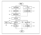
- FIG. 5 is a flowchart showing an outline of the procedure of the lens shape determination method according to the present invention.
- 6 to 7 are explanatory diagrams showing specific examples of specifying a predicted finished shape by the lens shape determination method according to the present invention.
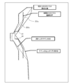
- FIG. 8 is an explanatory diagram showing a specific example of specifying a theoretical shape by the lens shape determination method according to the present invention.
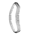
- FIG. 9 is explanatory drawing which shows the specific example of planar view of the shape comparison by the lens shape determination method based on this invention.
- the lens shape determination includes a predicted shape specifying step (Step 1, step is hereinafter abbreviated as “S”), a contact mode specifying step (S 2), a theoretical shape specifying step (S 3), It is performed through a shape comparison step (S4) and a pass / fail judgment step (S5).
- S predicted shape specifying step
- S 2 contact mode specifying step
- S 3 theoretical shape specifying step
- S4 shape comparison step
- S5 pass / fail judgment step
- the predicted shape specifying step (S1) is a step performed by the predicted shape specifying means 201b, and is a step for obtaining a predicted shape of the bevel cross-section in consideration of the amount of processing tool interference when performing bevel processing on an unprocessed spectacle lens.
- the predicted shape specifying unit 201b first sets measurement points at a plurality of locations in the circumferential direction of the spectacle lens. For example, the measurement points are set at 360 locations by dividing the circumferential direction of the spectacle lens by 1 °. Then, the predicted shape specifying unit 201b assumes a cross section parallel to the Z axis including the processing point at the periphery of the spectacle lens at each measurement point, and considers a change in the shape of the bevel on this cross section.
- the predicted shape specifying means 201b pays attention to the processing point on the periphery of the spectacle lens of the assumed cross section at a certain measurement point. Then, based on the position of the tool machining trajectory corresponding to the point to be machined in the assumed cross section, using the tool machining trajectory of several to several tens of points before and after that, the design of the assumed cross section to which attention is focused on the bevel shape The amount of interference of the rotary grindstone tool 241a is obtained.
- a movement simulation of the rotary grindstone tool 241a with respect to a certain work point is performed, thereby cutting the work point (see FIG. That is, the amount of tool interference) is sequentially calculated, and the bevel shape after the shape change due to the tool interference in the assumed cross section is obtained while using the envelope of the cross section shape.
- the bevel shape after this shape change becomes a predicted finish shape of the bevel cross section.
- the predicted shape specifying unit 201b performs a simulation process for obtaining the predicted finished shape of the bevel cross section for every measurement point, as shown in FIG.
- the predicted finished shape of the bevel cross section differs for each measurement point because the amount of interference of the rotary grindstone tool 241a differs at each measurement point.
- the shape indicated by the solid line is the predicted shape of the bevel cross section at each measurement point
- the shape indicated by the broken line is the bevel when no tool interference occurs (ie, design). Shape.
- the bevel shape of the entire spectacle lens is reproduced as shown in FIG. That is, it is possible to accurately obtain the predicted finish shape of the bevel cross-section over the entire circumference of the spectacle lens.
- the contact mode specifying step (S2) is a step performed by the contact mode specifying means 201c, and is a step of determining the contact mode of the stylus 251a with respect to the bevel of the predicted finished shape determined in the predicted shape specifying step (S1).
- the contact mode specifying unit 201c first recognizes the cross-sectional shape passing through the rotation axis of the stylus 251a based on the shape data of the stylus 251a.
- the stylus 251a is applied with a certain pressure toward the center of the spectacle lens to be measured. Therefore, as shown in FIG. 8, the stylus 251a having the V-shaped groove contact portion 251b always comes into contact with the bevel of the spectacle lens at two different points A1 and A2 in the contact portion 251b.
- the contact mode specifying unit 201c determines the contact mode of the stylus 251a.
- the contact mode specifying means 201c obtains the contact mode of the stylus 251a by performing the following simulation process.
- the contact mode specifying unit 201c pays attention to an assumed cross section at a certain measurement point.
- the cross-sectional shape of the stylus 251a corresponding to each assumed cross-section is made closer to the predicted finish shape of the bevel from a certain direction.
- one of the cross-sectional shapes of the stylus 251a in each assumed cross section and one of the predicted beveled shapes in each assumed cross-section always come into contact at least at one point.
- the contact state specifying means 201c moves the stylus 251a so as to shift the Z-direction coordinate of the stylus 251a upward. Further, if the contact is made at one point on the lower side of the contact portion 251b of the stylus 251a, the contact state specifying means 201c moves the stylus 251a so as to shift the Z-direction coordinate of the stylus 251a downward. Then, after being moved by a predetermined amount, the stylus 251a is again brought closer to the predicted finish shape of the bevel.
- the contact state specifying unit 201c repeats such processing until the stylus 251a comes into contact with the two points A1 and A2 with respect to the predicted finished shape of the bevel while gradually decreasing the movement amount of the stylus 251a. . Thereby, the state in which the stylus 251a is finally in contact with the two points A1 and A2 with respect to the predicted finish shape of the bevel, that is, the contact mode of the stylus 251a can be obtained.
- the contact state specifying unit 201c performs such a simulation process for all the measurement points for which the bevel finish prediction shape is obtained, thereby individually obtaining the contact state of the stylus 251a at each measurement point. That is, in consideration of the shape change of the bevel due to the tool interference, the state in which the stylus 251a of the shape measuring device 251 is in contact with the bevel after the shape change is confirmed.
- the theoretical shape specifying step (S3) is a step performed by the theoretical shape specifying means 201d, and a shape measurement result that will be obtained by the shape measuring instrument 251 when the contact mode obtained in the contact mode specifying step (S2) is reflected. Is obtained as a theoretical shape of the peripheral edge of the spectacle lens after beveling.
- the theoretical shape may be specified based on the locus of the stylus 251a when the stylus 251a is moved in the circumferential direction of the spectacle lens while the stylus 251a is in contact with the predicted finish of the bevel.
- the reference position of the stylus 251a at each measurement point in the contact mode (for example, the position of the rotation center axis).
- the locus of the stylus 251a is specified.
- the shape measuring instrument 251 calculates the bevel circumference
- the three-dimensional shape of the lens periphery in the spectacle lens having the predicted finish shape That is, the theoretical shape of the spectacle lens can be obtained. That is, the theoretical shape specifying unit 201d obtains the theoretical shape from the trajectory of the stylus 251a based on the processing contents of the predicted shape specifying unit 201b and the contact mode specifying unit 201c.
- the shape comparison step (S4) is a step performed by the shape comparison means 250c, and the actual shape actually obtained by the shape measuring instrument 251 with respect to the peripheral edge of the spectacle lens after beveling and the theoretical shape obtained in the theoretical shape specifying step (S3). Is a step of comparing The comparison result in the shape comparison step (S4) is used for pass / fail determination in a pass / fail determination step (S5) described later.
- the comparison between the actually measured shape and the theoretical shape is performed according to the coordinate system of the mechanism unit included in the lens processing machine 241 that performs the bevel processing on the spectacle lens that has obtained the actually measured shape.
- the mechanical unit of the lens processing machine 241 includes a cylindrical coordinate system and an orthogonal coordinate system.
- the cylindrical coordinate of R ⁇ z is used.
- the measured shape and the theoretical shape are both obtained from the movement trajectory of the stylus 251a, they can be expressed by numerical values in the cylindrical coordinate system. Specifically, first, both shapes are arranged on the same cylindrical coordinate while using the coordinate origin as a reference. This state is referred to as a “first state”.
- (A) to (C) there are mainly the following three types of (A) to (C) as differences that may occur between the actually measured shape and the theoretical shape.
- (B) A mode in which a positional difference (displacement) in the Z direction of the cylindrical coordinates occurs between the two shapes.
- (B) A mode in which a positional device (displacement) in the rotation direction ( ⁇ direction) of the cylindrical coordinates occurs between the two shapes.
- (C) A mode in which a positional difference (deviation) in the R direction of the cylindrical coordinates occurs between the two shapes.
- C-1 Deviation between the lens rotation center axis and the control signal for the distance between the machining tool axes.
- (C-2) Deviation between registered tool diameter and actual tool diameter.
- the shape comparison step (S4) since the determination with respect to the actually measured shape is performed based on the comparison result with the theoretical shape, the shape between both shapes can be obtained in any of the above-described modes (a) to (c). It is possible to accurately recognize the presence or absence of a difference (displacement). For example, as shown in FIG. 9B, consider a case where an actually measured shape (see the solid line in the figure) is compared with a design shape (see the two-dot chain line in the figure). In this case, since the design shape is calculated without considering the bevel thinning due to the interference of the processing tool, the design shape is different from the actually measured shape in which the occurrence of the bevel thinning is unavoidable.
- the shape is obtained by reflecting the contact mode of the stylus 251a with respect to the bevel cross-section while taking into account the shape change, so that both shapes are substantially the same shape. For this reason, if the measured shape is compared with the theoretical shape, the substantially same shape is overlapped (see, for example, part A in the figure), so that it is easy to overlap both shapes. It is possible to accurately recognize whether there is a misalignment. In particular, with respect to the above-described aspect (b), it is easy to determine the direction of rotation by comparing both shapes, and the amount of rotation can be accurately grasped.
- the actually measured shape is compared with the theoretical shape grasped as a reference instead of the design shape.
- This theoretical shape is obtained by reflecting the contact state of the stylus 251a of the shape measuring instrument 251 with respect to the bevel cross section while taking into account the shape change of the bevel due to the machining tool interference. Therefore, the theoretical shape is influenced by the occurrence of the machining tool interference. Has been reduced to a level that can be ignored.
- the pass / fail judgment step (S5) is a step performed by the shape comparison means 250c, and the pass / fail judgment for the measured shape, that is, the measured shape is desired while using the comparison result between the measured shape and the theoretical shape in the shape comparison step (S4). In this step, it is determined whether or not the shape is correct.
- the quality determination for the actually measured shape is performed by determining whether or not the difference amount (deviation amount) between the two shapes recognized through the comparison between the actually measured shape and the theoretical shape is within a preset allowable range. Specifically, it is conceivable to carry out such as determining that the product is acceptable if the amount of deviation between the actually measured shape and the theoretical shape is within an allowable range.
- the allowable range is individually set for the above three modes (A) to (C). Specifically, if the amount of misalignment is 0.1 mm or less for the mode (A), the product is determined to be acceptable, and if the amount of misalignment is 1 ° or less for the mode (B), the product is determined to be acceptable. And about the aspect of (c), if the deviation
- the value that defines the allowable range is not particularly limited and may be set as appropriate.
- FIG. 10 is a flowchart showing an outline of the procedure of the spectacle lens manufacturing method according to the present invention.
- the eyeglass lens manufacturing method described in the present embodiment includes a lens processing step (S6) and a post-processing shape measurement step (S7) in addition to the steps (S1 to S5) constituting the procedure of the lens shape determination method described above. Then, the spectacle lens is manufactured through the correction necessity determination step (S8) and the processing amount correction step (S9).
- the lens processing step (S6) and the post-processing shape measurement step (S7) are performed prior to the shape comparison step (S4). If it precedes a shape comparison step (S4), you may perform a parallel process with a prediction shape specific step (S1), a contact mode specific step (S2), and a theoretical shape specific step (S3).
- the correction necessity determination step (S8) and the machining amount correction step (S9) are performed after the shape comparison step (S4). If it is after the shape comparison step (S4), parallel processing with the pass / fail judgment step (S5) may be performed.
- the shape measuring instrument 251 measures the shape of the lens peripheral portion of the beveled spectacle lens after the bevel processing is performed in the lens processing step (S6). As a result, the shape measuring instrument 251 can obtain an actually measured shape of the beveled spectacle lens. That is, the measurement result of the shape measuring instrument 251 is sent from the shape measuring instrument 251 to the terminal computer 250 as the actual measurement shape of the beveled spectacle lens. Then, in the terminal computer 250, the measured shape and the theoretical shape are compared in the shape comparison step (S4).
- the difference amount (deviation amount) between the two shapes is within the allowable range.
- the spectacle lens is sent to another processing step (for example, a paint mark step) as necessary (S5a).
- the spectacle lens determined to be a rejected product that is, a defective product
- S5b the spectacle lens determined to be a rejected product
- the terminal computer 240 processes the lens processing machine 241 used in the lens processing step (S6). It is determined whether or not an amount correction is necessary. Similar to the pass / fail determination in the pass / fail determination step (S5), this determination may be performed based on whether or not the amount of deviation between the measured shape and the theoretical shape is within a preset allowable range. Specifically, if the amount of deviation between the actually measured shape and the theoretical shape is within the allowable range, the processing amount correction for the lens processing machine 241 is not necessary, but if the amount of deviation exceeds the allowable range, the lens is corrected. For example, it may be determined that the machining amount correction for the processing machine 241 should be performed.
- the allowable range used as a reference in the correction necessity determination step (S8) may be the same as the allowable range used in the quality determination step (S5). However, they are not necessarily the same, and different from the pass / fail determination in the pass / fail determination step (S5) may be used. Specifically, it is conceivable that the allowable range used as a reference in the correction necessity determination step (S8) is set to be stricter (to a narrower range) than the allowable range used in the quality determination step (S5). It is done. In this way, the machining amount correction is performed before the deviation amount between the actually measured shape and the theoretical shape exceeds the acceptable range of the pass / fail judgment, and it can be avoided in advance that the rejected product is generated. It becomes like this.
- the correction necessity determination step (S8) may be performed every time the comparison result in the shape comparison step (S4) is obtained (that is, every lens ordering job from the spectacle store 100 side). There is no need to perform the above process, and the process may be performed based on the statistical result of each job at a timing after processing a predetermined number of jobs. Specifically, statistics are taken as to whether or not the amount of deviation between the measured shape and the theoretical shape is within an allowable range over a plurality of jobs. A known technique may be used as a statistical processing method. If such statistical processing is used, in the correction necessity determination step (S8), it is possible to determine whether or not correction is necessary while eliminating abnormal values, and the accuracy of the determination result can be improved.
- the terminal computer 240 determines the actual measurement shape based on the comparison result between the actual measurement shape and the theoretical shape.
- the lens processing machine 241 that performs the bevel processing of the obtained spectacle lens is caused to correct the processing amount by an amount corresponding to the difference between the actually measured shape and the theoretical shape. That is, for the actually measured shape of the beveled spectacle lens that is the processing result of the lens processing machine 241, a so-called feedback correction that eliminates the deviation amount after recognizing the deviation amount from the theoretical shape is performed. That is, the processing machine 241 performs the processing. Therefore, when the bevel processing of the spectacle lens is newly performed by the lens processing machine 241 after the processing amount correction step (S9), the bevel processed spectacle lens has no difference (shift) between the actually measured shape and the theoretical shape. Is equal to
- the processing amount correction by the lens processing machine 241 performed in the processing amount correction step (S9) is performed only when it is determined that the processing amount correction is necessary in the correction necessity determination step (S8), that is, the actually measured shape and the theoretical shape. This is performed only when the amount of difference exceeds the allowable range set in advance. If it is determined in the correction necessity determination step (S8) that the machining amount correction is unnecessary, the processing is terminated without passing through the machining amount correction step (S9). Therefore, the machining amount correction is performed only when necessary, and the processing load on the terminal computer 240 or the like can be reduced as compared with, for example, the case where it is performed each time an actually measured shape is obtained.
- the processing amount correction by the lens processing machine 241 may be performed mechanically (physically) or may be performed by software.
- the machining amount correction performed mechanically includes the following.
- at least one of the terminal computer 240 or the lens processing machine 241 indicates that the processing amount correction is necessary and the processing to be corrected through information display using a display, for example.
- the amount is notified to the operator of the lens processing machine 241.
- the operator of the lens processing machine 241 adjusts, for example, the axial position of the processing tool with respect to the bevel processing mechanism of the lens processing machine 241 or the machine of the holding shaft for the unprocessed lens. Adjustment work such as adjusting the origin of the general rotation direction ( ⁇ direction) is performed.
- processing amount correction performed by software includes the following. For example, when it is determined that the machining amount correction is necessary, at least one of the main frame 201 or the terminal computer 240 recognizes that the machining amount correction is necessary and the machining amount to be corrected. The processing amount to be stored is stored and held. When the beveling is newly performed by the lens processing machine 241, the calculation of the three-dimensional processing trajectory data necessary for the beveling is performed by reflecting the stored processing amount as a correction value. Specifically, for example, the three-dimensional machining trajectory data is calculated by adding or subtracting the set value of the tool diameter by the correction value. The lens processing machine 241 that performs beveling based on the three-dimensional processing trajectory data by generating the three-dimensional processing trajectory data in consideration of such processing amount correction has a processing amount for performing the beveling processing. It will be corrected in software.
- correction of the processing amount by the lens processing machine 241 is mainly performed in each of the modes of occurrence of the difference (deviation) between the actually measured shape and the theoretical shape, that is, each of the above-described modes (a) to (c).
- (D) A correction mode in which the Z-axis position of the processing tool or the Z-axis position of the unprocessed lens in the lens processing machine 241 is moved mechanically or by software.
- a correction mode for example, in the lens processing machine 241, at least one of the unprocessed lens rotation axis or the processing tool rotation axis is in a position shifted from the original position due to poor adjustment or due to aging.
- the contact mode of the stylus 251a with the bevel of the spectacle lens having the predicted finish shape is determined, and the contact mode is reflected.
- the shape measurement result that would be obtained by the shape measuring instrument 251 is set as the theoretical shape of the peripheral edge of the spectacle lens after beveling, and the theoretical shape is compared with the actual measurement shape obtained by the shape measuring instrument 251, thereby the lens processing machine 241.
- the quality of the bevel processing result at is determined. Therefore, according to the present embodiment, when shape measurement is performed on a spectacle lens after beveling and a quality determination is performed on the result, a series of processing from the shape measurement to the quality determination is performed accurately and efficiently. Can be done.
- a series of processing from the above-described shape measurement to pass / fail judgment can be performed using the result of the bevel processing on the unprocessed lens. That is, in order to calibrate the lens processing machine 241, the lens processing machine 241 performs beveling on a test lens such as a flat lens that cannot cause processing tool interference, and the shape of the test lens after the beveling is measured. It is not necessary to measure the shape of the periphery of the lens using the device 251. Therefore, according to the present embodiment, when shape measurement is performed on a spectacle lens after beveling, and quality determination is performed on the result, a series of processes from shape measurement to quality determination are efficiently performed. To get.
- the contact mode of the stylus 251a with respect to the bevel is obtained, and the theoretical shape is identified while reflecting the result.
- the stylus 251a of the shape measuring instrument 251 that measures the shape of the beveled spectacle lens grasps how the stylus 251a actually contacts the bevel shape after the bevel shape is thinned or distorted due to tool interference.
- the theoretical shape is specified based on the grasped contents. Therefore, the result of specifying the theoretical shape conforms to the result of shape measurement using the stylus 251a. Therefore, a series of steps from shape measurement to pass / fail judgment are made as compared with the case where the grasping result of the contact state of the stylus 251a is not used. Further improvement in processing accuracy can be achieved.
- a new concept that is not known in the art that is, a theoretical shape of a spectacle lens that takes into account the amount of interference of the processing tool is introduced, and the theoretical shape is compared with the actually measured shape obtained by the shape measuring instrument 251. Based on the result, the processing amount correction corresponding to the difference amount (deviation amount) between the actually measured shape and the theoretical shape is performed on the lens processing machine 241 that performs the bevel processing of the spectacle lens that has obtained the actually measured shape. Make it. Therefore, for example, as a result of measuring the shape of the spectacle lens after the beveling process, if the lens peripheral portion of the spectacle lens is not as the desired shape, that is, the beveling process result is affected due to a defect in the lens processing machine 241.
- the feedback correction to the lens processing machine 241 is performed through the processing amount correction step (S9). Therefore, after the correction, the bevel processing result according to the desired shape is obtained. Be able to. That is, according to the present embodiment, it is possible to surely eliminate the cause that can be solved due to the malfunction of the lens processing machine 241 by performing the feedback correction.
- the lens processing machine 241 is used only when the amount of difference (deviation amount) between the actually measured shape and the theoretical shape exceeds a preset allowable range as a result of the comparison between the actually measured shape and the theoretical shape.
- the machining amount correction is performed only when necessary, so that the processing load on the terminal computer 240 or the like can be reduced as compared with, for example, the case where the machining shape is obtained each time a measured shape is obtained.
- an improvement in the accuracy of the determination result can be expected.
- measurement points are set at a plurality of locations in the circumferential direction of the spectacle lens, a predicted finished shape is obtained for each measurement point, and the contact mode of the stylus 251a is determined for each measurement point.
- a predicted finished shape or the like is not obtained for all the circumferential positions of the spectacle lens, but a predicted finished shape or the like is obtained for each of a plurality of preset measurement points.
- an interpolation process is performed based on the result of each measurement point. Therefore, although depending on the number of measurement points set, it is possible to reduce the calculation processing load when specifying the theoretical shape compared to the case where the predicted finished shape or the like is obtained for all locations in the circumferential direction of the spectacle lens. it can.
- the bevel shape, the shape of the rotary grindstone tool 241a, the shape of the stylus 251a, and the like exemplified in the present embodiment are merely examples, and the present invention is applied in the same manner even in the case of other shapes. It is possible.
- three modes (A) to (C) are given as examples of the generation mode (difference) between the actually measured shape and the theoretical shape, and the processing amount correction modes corresponding to these modes are (
- the three embodiments (d) to (f) are given as examples, but these are merely examples. That is, the mode of occurrence of difference (displacement) and the mode of processing amount correction may be only one of the three modes or all of the three modes.
- the present invention can be applied in exactly the same manner as in the case of the three aspects.
- 201 ... main frame, 201a ... data acquisition means, 201b ... predicted shape specification means, 201c ... contact mode specification means, 201d ... theoretical shape specification means, 201e ... theoretical shape notification means, 240 ... terminal computer, 240a ... determination result acquisition means , 240b ... correction instruction means, 241 ... lens processing machine, 241a ... rotary grindstone tool, 250 ... terminal computer, 250a ... theoretical shape acquisition means, 250b ... measured shape acquisition means, 250c ... shape comparison means, 250d ... determination result output means 251: Shape measuring instrument, 251a: Stylus
Landscapes
- Engineering & Computer Science (AREA)
- Chemical & Material Sciences (AREA)
- Ceramic Engineering (AREA)
- Inorganic Chemistry (AREA)
- Mechanical Engineering (AREA)
- Grinding And Polishing Of Tertiary Curved Surfaces And Surfaces With Complex Shapes (AREA)
- Eyeglasses (AREA)
Abstract
未加工の眼鏡レンズにヤゲン加工を行う際の加工ツール干渉量を考慮したヤゲン断面の仕上がり予測形状を求める予測形状特定手段201bと、前記仕上がり予測形状を有する眼鏡レンズのヤゲンに対するレンズ形状測定器251の測定子の接触態様を求める接触態様特定手段210cと、前記接触態様を反映させた場合に前記レンズ形状測定器251で得られるであろう形状測定結果をヤゲン加工後の眼鏡レンズ周縁の理論形状とする理論形状特定手段201dと、ヤゲン加工後の眼鏡レンズ周縁について前記レンズ形状測定器251で実際に得られる実測形状と前記理論形状とを比較し、その比較結果に基づいて当該実測形状に対する良否判定を行う形状比較手段250cと、を備えてレンズ加工制御装置を構成する。
Description
本発明は、眼鏡レンズのヤゲン加工を行う際に用いられるレンズ加工制御装置、レンズ加工制御プログラム、レンズ形状判定方法および眼鏡レンズの製造方法に関する。
眼鏡フレームに嵌め込まれる眼鏡レンズは、未加工レンズに対する玉型加工を経て形成される。玉型加工は、レンズ周縁部を眼鏡フレームに枠入れ可能な形状にする加工であり、一般に玉型加工機と呼ばれるレンズ加工機を用いて行われる。玉型加工を行うと、その加工後の眼鏡レンズは、枠入れすべき眼鏡フレームの枠形状に対応した形状のヤゲンがレンズ周縁部に形成される。以下、ヤゲンを形成する玉型加工を「ヤゲン加工」という。
このようなヤゲン加工を行った後、その加工後の眼鏡レンズについては、レンズ周縁部が所望形状通りに加工されているか否かの良否判定をする必要がある。そのため、ヤゲン加工を行うレンズ加工現場では、レンズ周縁部の形状を測定するレンズ形状測定器を使用して、加工後のレンズ周縁部の形状を測定することが一般的である。その場合に使用されるレンズ形状測定器としては、スタイラスと呼ばれる測定子をレンズ周縁部に当接させつつレンズ周方向に移動させることで、レンズ周縁部の形状測定を行うように構成されたものが知られている(例えば、特許文献1参照)。
しかしながら、上述した構成のレンズ形状測定器を使用してレンズ周縁部の形状測定を行った場合は、以下に述べる理由により、その形状測定から良否判定にまで至る一連の処理を、必ずしも正確かつ効率的に行い得るとは限らない。
ヤゲン加工後にレンズ周縁部が所望形状通りに加工されない要因としては、主に、ヤゲン加工を行う際に生じ得る加工ツール干渉に起因するものと、レンズ加工機における不具合に起因するものとがある。
ヤゲン加工の際に生じる加工ツール干渉は、以下のようなものである。未加工レンズに対してヤゲン加工を行う場合には、加工すべき玉型形状、加工されるレンズのカーブ、加工に用いる加工ツール(研削・切削ツール)の径、形成すべきヤゲン形状等の影響によって、加工中に加工ツールとレンズの被加工箇所とが理論上の切削点以外においても干渉することがある。これを「加工ツール干渉」という。加工ツール干渉が生じると、理論上の切削点以外も加工されてしまうので、形成されるヤゲンの形状に細りや歪み等が発生してしまう。したがって、加工ツール干渉は、ヤゲン加工後にレンズ周縁部が所望形状通りに加工されない要因となるのである。
なお、加工ツール干渉は、例えば平レンズに加工を行う場合のように、ヤゲン先端の周方向における軌跡(以下「ヤゲン先端軌跡」という。)がZ軸方向(レンズ光軸方向)に変化しなければ、加工ツールの位置もZ軸方向に変化する必要がないため、発生することがない。ところが、一般的な眼鏡レンズは、処方内容に応じたカーブを有しており、ヤゲン先端軌跡がZ軸方向に変化を持つ場合が殆どであるため、加工ツール干渉の発生を回避することが困難である。
なお、加工ツール干渉は、例えば平レンズに加工を行う場合のように、ヤゲン先端の周方向における軌跡(以下「ヤゲン先端軌跡」という。)がZ軸方向(レンズ光軸方向)に変化しなければ、加工ツールの位置もZ軸方向に変化する必要がないため、発生することがない。ところが、一般的な眼鏡レンズは、処方内容に応じたカーブを有しており、ヤゲン先端軌跡がZ軸方向に変化を持つ場合が殆どであるため、加工ツール干渉の発生を回避することが困難である。
また、レンズ加工機における不具合とは、ヤゲン加工の結果に影響を及ぼすような不具合のことをいう。具体的には、レンズ加工機において未加工レンズ回転軸または加工ツール回転軸の少なくとも一方が調整不良や経時的な理由等で本来の位置からずれた位置にあるような不具合、未加工レンズがブロッキングされた保持治具をレンズ加工機へ装着した際の回転方向(θ方向)の原点位置が作業ミス等で本来の位置からずれた位置にあるような不具合、レンズ加工機で使用する加工ツールについてのツール径の値についての設定ミスがあるような不具合等が挙げられる。このようなレンズ加工機における不具合が生じていると、そのレンズ加工機を用いてヤゲン加工を行った後のレンズ周縁部は、その形状が所望形状とは異なるものとなってしまう。つまり、レンズ加工機における不具合は、ヤゲン加工後にレンズ周縁部が所望形状通りに加工されない要因となるのである。なお、レンズ加工機における不具合は、その不具合を具体的に特定する内容を当該レンズ加工機にフィードバックすれば、当該不具合の解消を図ることが可能である。
このように、眼鏡レンズのレンズ周縁部が所望形状通りにならない要因としては、加工ツール干渉に因るものとレンズ加工機の不具合に因るものとの二つがある。ところが、従来におけるレンズ周縁部の形状測定では、これら二つの要因の切り分けを行っていない。そのため、例えば形状測定によってレンズ周縁部が所望形状通りではないという判定結果を得ても、その結果が上述した二つの要因のどちらに因るか、すなわち不可避か解消可能かが分からないので、レンズ加工機へのフィードバックを行っても、所望形状通りのヤゲン加工結果が得られるようになるとは限らない。つまり、従来の形状測定では、その形状測定から良否判定にまで至る一連の処理を、必ずしも正確に行い得るとは限らない。
この点については、例えば、所定タイミングでレンズ加工機のキャリブレーションを行うことで対応することも考えられる。具体的には、加工ツール干渉が生じ得ない平レンズまたはこれと同等に扱える所定レンズをテストレンズとして用い、予め設定された定期的なタイミングで、そのテストレンズに対してレンズ加工機でヤゲン加工を行い、そのヤゲン加工後のテストレンズについてレンズ形状測定器を使用してレンズ周縁部の形状測定を行い、その結果、レンズ周縁部が所望形状通りに加工されていなければ、レンズ加工機へのフィードバックを行って当該レンズ加工機における不具合の解消を図るようにする。
ところが、その場合には、レンズ加工機のキャリブレーションのために、本来は加工対象とはならないテストレンズについて、ヤゲン加工や形状測定等を行う必要が生じてしまう。つまり、テストレンズを処理する必要が生じてしまう分、効率的な処理の実現が困難になってしまう。
ところが、その場合には、レンズ加工機のキャリブレーションのために、本来は加工対象とはならないテストレンズについて、ヤゲン加工や形状測定等を行う必要が生じてしまう。つまり、テストレンズを処理する必要が生じてしまう分、効率的な処理の実現が困難になってしまう。
そこで、本発明は、ヤゲン加工後の眼鏡レンズに対する形状測定を行って、その結果に対する良否判定を行う場合に、その形状測定から良否判定にまで至る一連の処理を、正確かつ効率的に行うことを可能にするレンズ加工制御装置、レンズ加工制御プログラム、レンズ形状判定方法および眼鏡レンズの製造方法を提供することを目的とする。
上述した目的達成のために、本願発明者は、ヤゲン形状に細りや歪み等が発生する要因となる、ヤゲン加工に用いる加工ツールとレンズの被加工箇所との干渉について検討した。レンズカーブ等を考慮すると干渉の発生は不可避であるが、そのときの干渉量は、加工ツールの形状や軌跡、加工されるレンズのカーブや玉型形状等といった、ヤゲン加工を行う段階では既知となっている情報に基づいて特定することが可能である。
このことから、本願発明者は、加工ツール干渉量を考慮したヤゲン断面の仕上がり予測形状を求め、その仕上がり予測形状を有する眼鏡レンズのヤゲンに対するレンズ形状測定器の測定子の接触態様を求め、その接触態様を反映させた場合にレンズ形状測定器で得られるであろう形状測定結果をヤゲン加工後の眼鏡レンズ周縁の理論上の形状(以下、単に「理論形状」という。)とし、その理論形状を基準にその後の処理を行えば、ヤゲン加工結果に対する良否判定にあたり、加工ツール干渉の発生による影響を無視できる程度に軽減し得るのではないかとの着想を得た。つまり、ヤゲン形状の細りや歪み等の発生を容認した上で、その発生要因となる加工ツール干渉量を考慮した眼鏡レンズの理論形状という従来にはない新しい概念を取り入れることで、ヤゲン加工結果に対する良否判定にあたり、加工ツール干渉の発生による影響を無視できる程度に軽減して、レンズ周縁部が所望形状通りに加工されない他の要因であるレンズ加工機の不具合による影響の顕在化が図れると考えた。
本発明は、上述した本願発明者による新たな着想に基づいてなされたものである。
このことから、本願発明者は、加工ツール干渉量を考慮したヤゲン断面の仕上がり予測形状を求め、その仕上がり予測形状を有する眼鏡レンズのヤゲンに対するレンズ形状測定器の測定子の接触態様を求め、その接触態様を反映させた場合にレンズ形状測定器で得られるであろう形状測定結果をヤゲン加工後の眼鏡レンズ周縁の理論上の形状(以下、単に「理論形状」という。)とし、その理論形状を基準にその後の処理を行えば、ヤゲン加工結果に対する良否判定にあたり、加工ツール干渉の発生による影響を無視できる程度に軽減し得るのではないかとの着想を得た。つまり、ヤゲン形状の細りや歪み等の発生を容認した上で、その発生要因となる加工ツール干渉量を考慮した眼鏡レンズの理論形状という従来にはない新しい概念を取り入れることで、ヤゲン加工結果に対する良否判定にあたり、加工ツール干渉の発生による影響を無視できる程度に軽減して、レンズ周縁部が所望形状通りに加工されない他の要因であるレンズ加工機の不具合による影響の顕在化が図れると考えた。
本発明は、上述した本願発明者による新たな着想に基づいてなされたものである。
本発明の第1の態様は、未加工の眼鏡レンズにヤゲン加工を行う際の加工ツール干渉量を考慮したヤゲン断面の仕上がり予測形状を求める予測形状特定手段と、前記仕上がり予測形状を有する眼鏡レンズのヤゲンに対するレンズ形状測定器の測定子の接触態様を求める接触態様特定手段と、前記接触態様を反映させた場合に前記レンズ形状測定器で得られるであろう形状測定結果をヤゲン加工後の眼鏡レンズ周縁の理論形状とする理論形状特定手段と、ヤゲン加工後の眼鏡レンズ周縁について前記レンズ形状測定器で実際に得られる実測形状と前記理論形状とを比較し、その比較結果に基づいて当該実測形状に対する良否判定を行う形状比較手段と、を備えることを特徴とするレンズ加工制御装置である。
本発明の第2の態様は、第1の態様に記載の発明において、前記実測形状と前記理論形状との比較結果に基づいて、当該実測形状を得た眼鏡レンズのヤゲン加工を行ったレンズ加工機に、当該実測形状と当該理論形状との相違量に対応する量の加工量補正を行わせる補正指示手段を備えることを特徴とする。
本発明の第3の態様は、第2の態様に記載の発明において、前記補正指示手段は、前記実測形状と前記理論形状との相違量が予め設定された許容範囲を超えた場合にのみ、前記レンズ加工機に加工量補正を行わせることを特徴とする。
本発明の第4の態様は、第1から第3のいずれか1態様に記載の発明において、前記予測形状特定手段は、眼鏡レンズの周方向の複数箇所に設定された測定点毎に、前記仕上がり予測形状を求め、前記接触態様特定手段は、前記測定点毎に、前記仕上がり予測形状のヤゲンに対する前記測定子の接触態様を求めることを特徴とする。
本発明の第5の態様は、コンピュータを、未加工の眼鏡レンズにヤゲン加工を行う際の加工ツール干渉量を考慮したヤゲン断面の仕上がり予測形状を求める予測形状特定手段と、前記仕上がり予測形状を有する眼鏡レンズのヤゲンに対するレンズ形状測定器の測定子の接触態様を求める接触態様特定手段と、前記接触態様を反映させた場合に前記レンズ形状測定器で得られるであろう形状測定結果をヤゲン加工後の眼鏡レンズ周縁の理論形状とする理論形状特定手段と、ヤゲン加工後の眼鏡レンズ周縁について前記レンズ形状測定器で実際に得られる実測形状と前記理論形状とを比較し、その比較結果に基づいて当該実測形状に対する良否判定を行う形状比較手段として機能させることを特徴とするレンズ加工制御プログラムである。
本発明の第6の態様は、第5の態様に記載の発明において、前記コンピュータを、前記実測形状と前記理論形状との比較結果に基づいて、当該実測形状を得た眼鏡レンズのヤゲン加工を行ったレンズ加工機に、当該実測形状と当該理論形状との相違量に対応する量の加工量補正を行わせる補正指示手段として機能させることを特徴とする。
本発明の第7の態様は、未加工の眼鏡レンズにヤゲン加工を行う際の加工ツール干渉量を考慮したヤゲン断面の仕上がり予測形状を求める予測形状特定ステップと、前記仕上がり予測形状を有する眼鏡レンズのヤゲンに対するレンズ形状測定器の測定子の接触態様を求める接触態様特定ステップと、前記接触態様を反映させた場合に前記レンズ形状測定器で得られるであろう形状測定結果をヤゲン加工後の眼鏡レンズ周縁の理論形状とする理論形状特定ステップと、ヤゲン加工後の眼鏡レンズ周縁について前記レンズ形状測定器で実際に得られる実測形状と前記理論形状とを比較し、その比較結果を当該実測形状に対する良否判定に用いる形状比較ステップと、を備えることを特徴とするレンズ形状判定方法である。
本発明の第8の態様は、第7の態様に記載のレンズ形状判定方法を用いた前記実測形状と前記理論形状との比較結果に基づいて、当該実測形状を得た眼鏡レンズのヤゲン加工を行ったレンズ加工機に、当該実測形状と当該理論形状との相違量に対応する量の加工量補正を行わせる加工量補正工程を備えることを特徴とする眼鏡レンズの製造方法である。
本発明の第2の態様は、第1の態様に記載の発明において、前記実測形状と前記理論形状との比較結果に基づいて、当該実測形状を得た眼鏡レンズのヤゲン加工を行ったレンズ加工機に、当該実測形状と当該理論形状との相違量に対応する量の加工量補正を行わせる補正指示手段を備えることを特徴とする。
本発明の第3の態様は、第2の態様に記載の発明において、前記補正指示手段は、前記実測形状と前記理論形状との相違量が予め設定された許容範囲を超えた場合にのみ、前記レンズ加工機に加工量補正を行わせることを特徴とする。
本発明の第4の態様は、第1から第3のいずれか1態様に記載の発明において、前記予測形状特定手段は、眼鏡レンズの周方向の複数箇所に設定された測定点毎に、前記仕上がり予測形状を求め、前記接触態様特定手段は、前記測定点毎に、前記仕上がり予測形状のヤゲンに対する前記測定子の接触態様を求めることを特徴とする。
本発明の第5の態様は、コンピュータを、未加工の眼鏡レンズにヤゲン加工を行う際の加工ツール干渉量を考慮したヤゲン断面の仕上がり予測形状を求める予測形状特定手段と、前記仕上がり予測形状を有する眼鏡レンズのヤゲンに対するレンズ形状測定器の測定子の接触態様を求める接触態様特定手段と、前記接触態様を反映させた場合に前記レンズ形状測定器で得られるであろう形状測定結果をヤゲン加工後の眼鏡レンズ周縁の理論形状とする理論形状特定手段と、ヤゲン加工後の眼鏡レンズ周縁について前記レンズ形状測定器で実際に得られる実測形状と前記理論形状とを比較し、その比較結果に基づいて当該実測形状に対する良否判定を行う形状比較手段として機能させることを特徴とするレンズ加工制御プログラムである。
本発明の第6の態様は、第5の態様に記載の発明において、前記コンピュータを、前記実測形状と前記理論形状との比較結果に基づいて、当該実測形状を得た眼鏡レンズのヤゲン加工を行ったレンズ加工機に、当該実測形状と当該理論形状との相違量に対応する量の加工量補正を行わせる補正指示手段として機能させることを特徴とする。
本発明の第7の態様は、未加工の眼鏡レンズにヤゲン加工を行う際の加工ツール干渉量を考慮したヤゲン断面の仕上がり予測形状を求める予測形状特定ステップと、前記仕上がり予測形状を有する眼鏡レンズのヤゲンに対するレンズ形状測定器の測定子の接触態様を求める接触態様特定ステップと、前記接触態様を反映させた場合に前記レンズ形状測定器で得られるであろう形状測定結果をヤゲン加工後の眼鏡レンズ周縁の理論形状とする理論形状特定ステップと、ヤゲン加工後の眼鏡レンズ周縁について前記レンズ形状測定器で実際に得られる実測形状と前記理論形状とを比較し、その比較結果を当該実測形状に対する良否判定に用いる形状比較ステップと、を備えることを特徴とするレンズ形状判定方法である。
本発明の第8の態様は、第7の態様に記載のレンズ形状判定方法を用いた前記実測形状と前記理論形状との比較結果に基づいて、当該実測形状を得た眼鏡レンズのヤゲン加工を行ったレンズ加工機に、当該実測形状と当該理論形状との相違量に対応する量の加工量補正を行わせる加工量補正工程を備えることを特徴とする眼鏡レンズの製造方法である。
本発明によれば、ヤゲン加工後の眼鏡レンズに対する形状測定を行って、その結果に対する良否判定を行う場合に、その形状測定から良否判定にまで至る一連の処理を、正確かつ効率的に行うことができる。
以下、本発明の実施形態を、図面に基づいて説明する。
本実施形態では、以下の順序で項分けをして説明を行う。
1.システム構成
2.機能構成
3.レンズ形状判定手順
4.眼鏡レンズ製造方法の手順
5.本実施形態の効果
6.変形例等
本実施形態では、以下の順序で項分けをして説明を行う。
1.システム構成
2.機能構成
3.レンズ形状判定手順
4.眼鏡レンズ製造方法の手順
5.本実施形態の効果
6.変形例等
<1.システム構成>
先ず、本実施形態におけるシステム全体の構成について説明する。なお、以下に説明する事項以外については、公知技術(例えば、特許第3075870号公報参照)を利用して実現すればよいものとする。
図1は、本発明に係るレンズ加工制御装置を含む眼鏡レンズ供給システムの全体構成例を示す模式図である。
先ず、本実施形態におけるシステム全体の構成について説明する。なお、以下に説明する事項以外については、公知技術(例えば、特許第3075870号公報参照)を利用して実現すればよいものとする。
図1は、本発明に係るレンズ加工制御装置を含む眼鏡レンズ供給システムの全体構成例を示す模式図である。
(全体構成)
図1に示すように、本実施形態で例に挙げる眼鏡レンズの供給システムは、眼鏡レンズの発注側である眼鏡店100と、レンズ加工側であるレンズメーカの工場200とに、分散配置されて構成されている。なお、図例では、眼鏡店100を1つしか示していないが、実際には1つの工場200に対して複数の眼鏡店100が存在していてもよい。
図1に示すように、本実施形態で例に挙げる眼鏡レンズの供給システムは、眼鏡レンズの発注側である眼鏡店100と、レンズ加工側であるレンズメーカの工場200とに、分散配置されて構成されている。なお、図例では、眼鏡店100を1つしか示していないが、実際には1つの工場200に対して複数の眼鏡店100が存在していてもよい。
(眼鏡店側構成)
眼鏡店100には、オンライン用の端末コンピュータ101と、眼鏡フレームの枠形状を測定して枠形状データを出力する眼鏡フレーム測定機102と、が設置されている。
端末コンピュータ101は、キーボードやマウス等の入力装置や液晶パネル等の表示装置を備えるとともに、公衆通信回線網300を介して工場200側に接続されて、当該工場200側との間でデータ授受を行うように構成されている。
眼鏡フレーム測定機102は、眼鏡フレームの左右枠の枠溝に測定子を接触させ、その測定子を所定点中心に回転させて枠溝の形状の円筒座標値を3次元的に検出することで、当該眼鏡フレームの枠形状を測定する。そして、その測定結果を当該眼鏡フレームの枠形状データとして、端末コンピュータ101に出力するように構成されている。
眼鏡店100には、オンライン用の端末コンピュータ101と、眼鏡フレームの枠形状を測定して枠形状データを出力する眼鏡フレーム測定機102と、が設置されている。
端末コンピュータ101は、キーボードやマウス等の入力装置や液晶パネル等の表示装置を備えるとともに、公衆通信回線網300を介して工場200側に接続されて、当該工場200側との間でデータ授受を行うように構成されている。
眼鏡フレーム測定機102は、眼鏡フレームの左右枠の枠溝に測定子を接触させ、その測定子を所定点中心に回転させて枠溝の形状の円筒座標値を3次元的に検出することで、当該眼鏡フレームの枠形状を測定する。そして、その測定結果を当該眼鏡フレームの枠形状データとして、端末コンピュータ101に出力するように構成されている。
これら端末コンピュータ101および眼鏡フレーム測定機102が設置された眼鏡店100側では、顧客が所望する眼鏡レンズの処方値等が端末コンピュータ101で入力され、かつ、顧客が所望する眼鏡フレームの枠形状データが眼鏡フレーム測定機102から端末コンピュータ101に対して出力されると、端末コンピュータ101がこれらの内容を、公衆通信回線網300を介して工場200側のメインフレーム201にオンラインで転送するようになっている。
(工場側構成)
一方、工場200側には、眼鏡店100側の端末コンピュータ101と公衆通信回線網300を介して接続するメインフレーム201が設置されている。メインフレーム201は、眼鏡レンズ加工設計プログラム、ヤゲン加工設計プログラム等を実行するコンピュータ装置としての機能を備えており、眼鏡店100側の端末コンピュータ101からの入力データに基づき、ヤゲン形状を含めたレンズ形状を演算するように構成されている。また、メインフレーム201は、公衆通信回線網300の他に、工場200側に設置された複数の端末コンピュータ210,220,230,240,250とLAN202を介して接続しており、レンズ形状の演算結果を各端末コンピュータ210,220,230,240,250へ送るようになっている。
一方、工場200側には、眼鏡店100側の端末コンピュータ101と公衆通信回線網300を介して接続するメインフレーム201が設置されている。メインフレーム201は、眼鏡レンズ加工設計プログラム、ヤゲン加工設計プログラム等を実行するコンピュータ装置としての機能を備えており、眼鏡店100側の端末コンピュータ101からの入力データに基づき、ヤゲン形状を含めたレンズ形状を演算するように構成されている。また、メインフレーム201は、公衆通信回線網300の他に、工場200側に設置された複数の端末コンピュータ210,220,230,240,250とLAN202を介して接続しており、レンズ形状の演算結果を各端末コンピュータ210,220,230,240,250へ送るようになっている。
端末コンピュータ210には、荒擦り機(カーブジェネレータ)211と、砂掛け研磨機212とが接続されている。そして、端末コンピュータ210は、メインフレーム201から送られた演算結果に従いつつ、荒擦り機211と砂掛け研磨機212とを制御して、前面加工済みレンズの裏面(後面)の曲面仕上げを行う。
端末コンピュータ220には、レンズメータ221と、肉厚計222とが接続されている。そして、端末コンピュータ220は、レンズメータ221と肉厚計222とで得られた測定値と、メインフレーム201から送られた演算結果とを比較して、レンズ裏面(後面)の曲面仕上げが完了した眼鏡レンズの受入れ検査を行うとともに、合格レンズには光学中心を示すマーク(3点マーク)を付す。
端末コンピュータ230には、マーカ231と、画像処理機232とが接続されている。そして、端末コンピュータ230は、メインフレーム201から送られた演算結果に従いつつ、マーカ231と画像処理機232とを制御して、眼鏡レンズの縁摺り加工およびヤゲン加工をする際にレンズをブロック(保持)すべきブロッキング位置を決定し、また、ブロッキング位置マークを付す。このブロッキング位置マークに従い、ブロック用の治工具がレンズに固定される。
端末コンピュータ240には、NC制御のレンズ加工機241と、チャックインタロック242とが接続されている。そして、端末コンピュータ240は、メインフレーム201から送られた演算結果に従いつつ、レンズ加工機241を制御して、そのレンズ加工機241に眼鏡レンズの玉型加工を行わせる。玉型加工には、未加工レンズを眼鏡フレーム枠形状に合わせて研削加工する「縁摺り加工」と、縁摺り加工されたレンズにヤゲンを設ける「ヤゲン加工」とが含まれる。このようなヤゲン加工を含む玉型加工を行うレンズ加工機241は、本発明における「レンズ加工機」に相当する。
端末コンピュータ250には、ヤゲン加工後のレンズ周縁部の形状を測定する形状測定器251が接続されている。このような形状測定を行う形状測定器251は、本発明における「レンズ形状測定器」に相当する。そして、端末コンピュータ250は、形状測定器251を制御して、当該形状測定器251にヤゲン加工済み眼鏡レンズの周長および形状を測定させるとともに、その測定結果をメインフレーム201から送られた演算結果と比較して、ヤゲン加工の良否判定を行う。
以上のような構成の工場200側では、眼鏡店100側の端末コンピュータ101からの入力データに基づき、メインフレーム201がヤゲン形状を含めた眼鏡レンズ形状を演算するとともに、その演算結果に従いつつ各端末コンピュータ210,220,230,240,250がレンズ加工機241や形状測定器251等を制御することで、ヤゲン加工済みで、かつ、レンズ周縁形状およびヤゲン形状が眼鏡フレーム枠の形状に合致する眼鏡レンズの製造を行うようになっている。
なお、上述した構成の眼鏡レンズの供給システムでは、詳細を後述するように、主としてメインフレーム201、端末コンピュータ240および端末コンピュータ250において、レンズ加工機241で眼鏡レンズの玉型加工を行うために必要な制御処理が行われる。すなわち、メインフレーム201、端末コンピュータ240および端末コンピュータ250は、本発明に係る「レンズ加工制御装置」としての機能を備えている。
また、上述した構成の眼鏡レンズの供給システムでは、詳細を後述するように、主としてメインフレーム201および端末コンピュータ250において本発明に係る「レンズ形状判定方法」が実施される。
また、上述した構成の眼鏡レンズの供給システムでは、詳細を後述するように、主としてメインフレーム201、端末コンピュータ240、レンズ加工機241、端末コンピュータ250および形状測定器251によって、本発明に係る「眼鏡レンズの製造方法」が実施される。
また、上述した構成の眼鏡レンズの供給システムでは、詳細を後述するように、主としてメインフレーム201および端末コンピュータ250において本発明に係る「レンズ形状判定方法」が実施される。
また、上述した構成の眼鏡レンズの供給システムでは、詳細を後述するように、主としてメインフレーム201、端末コンピュータ240、レンズ加工機241、端末コンピュータ250および形状測定器251によって、本発明に係る「眼鏡レンズの製造方法」が実施される。
<2.機能構成>
次に、上述した構成の眼鏡レンズの供給システムにおいて、本発明に係るレンズ加工制御装置としての機能するための機能構成、並びに、本発明に係るレンズ形状判定方法および眼鏡レンズの製造方法を実施するための機能構成について説明する。
次に、上述した構成の眼鏡レンズの供給システムにおいて、本発明に係るレンズ加工制御装置としての機能するための機能構成、並びに、本発明に係るレンズ形状判定方法および眼鏡レンズの製造方法を実施するための機能構成について説明する。
(レンズ加工機)
ここで、先ず、眼鏡レンズの縁摺り加工およびヤゲン加工を行うレンズ加工機241について説明する。
ここで、先ず、眼鏡レンズの縁摺り加工およびヤゲン加工を行うレンズ加工機241について説明する。
レンズ加工機241は、Y軸方向(スピンドル軸方向に垂直方向)に移動制御されて眼鏡レンズの縁摺り加工やヤゲン加工を行う研削用の回転砥石を有し、また、レンズを固定するブロック治工具の回転角制御(スピンドル軸回転方向)と、Z軸方向(スピンドル軸方向)に砥石または眼鏡レンズを移動制御してヤゲン加工を行うZ軸制御との、少なくとも3軸制御が可能なNC制御の研削装置である。
図2は、レンズ加工機241がヤゲン加工に用いる回転砥石ツールの一例を示す説明図である。図例の回転砥石ツール241aは、レンズ前面側のヤゲン加工斜面とレンズ後面側のヤゲン加工斜面とのそれぞれに対応するように形成されたヤゲン溝241bを持つ砥石部241cを備えている。そして、回転軸241dを中心に回転しながらレンズ周縁に沿って移動することで、眼鏡レンズ241eの全周に対してヤゲン加工を行うように構成されている。
このような回転砥石ツール241aをレンズ周縁に沿って移動させる際の軌跡は、メインフレーム201が算出する。メインフレーム201は、ヤゲン加工設計プログラムの起動により、ヤゲン加工設計演算を行う。すなわち、眼鏡店100側の端末コンピュータ101からの入力データに基づき、3次元のヤゲン加工の設計演算を行って、最終的な3次元ヤゲン先端形状を算出するとともに、この算出した3次元ヤゲン先端形状を基に、所定の半径の回転砥石ツール241aで研削加工する際の加工座標上の3次元加工軌跡データを算出する。
ただし、メインフレーム201が算出する3次元加工軌跡データは、3次元ヤゲン先端形状に対応したものなので、Z軸方向への変位を持つ場合が殆どである。そのため、レンズ加工機241においては、メインフレーム201からの3次元加工軌跡データに従ってヤゲン加工を行うと、データ上で想定されるヤゲン加工斜面に対して回転砥石ツール241aのヤゲン溝が3次元的に干渉してしまい、実際に加工されるヤゲン頂点が想定のものより小さくなるといったことが起こり得る。つまり、レンズ加工機241では、メインフレーム201からの3次元加工軌跡データのとおりにヤゲン加工を行っても、当該ヤゲン加工の際にZ軸方向に変位する回転砥石ツール241aとの干渉により、形成されるヤゲンの形状に細りや歪み等が発生してしまい、当該ヤゲン加工の際に想定した位置にヤゲンが位置しないといったことが起こり得るのである。このようなツール干渉の発生は、レンズカーブ等を考慮すると不可避であると言える。
(形状測定器)
続いて、ヤゲン加工済のレンズの周長および形状を測定する形状測定器251について説明する。
続いて、ヤゲン加工済のレンズの周長および形状を測定する形状測定器251について説明する。
形状測定器251は、ヤゲン頂点測定用の測定子としてのスタイラスを備えており、そのスタイラスを用いてヤゲン加工済み眼鏡レンズの周長および形状を測定するように構成されている。
図3は、形状測定器251が備えるスタイラスの一例を示す説明図である。図例のスタイラス251aは、予め決められたヤゲンの形状に合致するV字状溝を円周に沿って設けた接触部251bを有しており、この接触部251bがヤゲン加工済み眼鏡レンズのヤゲン251cに当接されるように構成されている。
このようなスタイラス251aを、形状測定器251は、眼鏡レンズのヤゲン251cに当接させた状態で、そのレンズの周方向に移動させながら測定を行う。さらに詳しくは、スタイラス251aを転動させながら移動させ、そのときの各ヤゲン251cの3次元の円筒座標値を測定する。すなわち、スタイラス251aのレンズ周方向の移動距離、回転角度、および上下移動距離を測定する。そして、こうして測定されたヤゲン251cの3次元の円筒座標値から、スタイラスによって予め定められている仮想ヤゲン頂点の通過軌跡を認識して、その通過軌跡の周長および3次元形状を算出し、これをヤゲン加工済み眼鏡レンズの周長および形状として端末コンピュータ250へ送るのである。
(メインフレームおよび端末コンピュータの機構構成)
続いて、メインフレーム201および端末コンピュータ240,250における機能構成について詳しく説明する。
図4は、メインフレーム201および端末コンピュータ240,250の機能構成例を示すブロック図である。
続いて、メインフレーム201および端末コンピュータ240,250における機能構成について詳しく説明する。
図4は、メインフレーム201および端末コンピュータ240,250の機能構成例を示すブロック図である。
図例のように、メインフレーム201は、データ取得手段201a、予測形状特定手段201b、接触態様特定手段201c、理論形状特定手段201dおよび理論形状通知手段201eとしての機能を備えている。
また、端末コンピュータ250は、理論形状取得手段250a、実測形状取得手段250b、形状比較手段250cおよび判定結果出力手段250dとしての機能を備えている。
また、端末コンピュータ240は、判定結果取得手段240aおよび補正指示手段240bとしての機能を備えている。
以下、これらの各手段201a~201e,250a~250d,240a~240bについて順に説明する。
また、端末コンピュータ250は、理論形状取得手段250a、実測形状取得手段250b、形状比較手段250cおよび判定結果出力手段250dとしての機能を備えている。
また、端末コンピュータ240は、判定結果取得手段240aおよび補正指示手段240bとしての機能を備えている。
以下、これらの各手段201a~201e,250a~250d,240a~240bについて順に説明する。
データ取得手段201aは、後述する理論形状特定に必要となるデータの取得を行う。取得するデータとしては、例えば、縁摺り加工およびヤゲン加工を行った後のレンズ形状を特定するためのデータ(レンズカーブデータ等)、レンズ加工機241の回転砥石ツール241aの形状データ、その回転砥石ツール241aで研削加工する際の加工座標上の3次元加工軌跡データ、形状測定器251のスタイラス251aの形状データ等が挙げられる。これらのデータの取得は、眼鏡店100側の端末コンピュータ101、工場200側のレンズ加工機241や形状測定器251等にアクセスすることで行ってもよいし、あるいはこれらのデータを工場200側で一括管理するために設けられた図示せぬデータベースにアクセスすることで行ってもよい。
予測形状特定手段201bは、上述したようにレンズ加工機241でのヤゲン加工の際にツール干渉の発生が不可避であることから、データ取得手段201aが取得したデータに基づき、当該ヤゲン加工を行う際の加工ツール干渉量を考慮したヤゲン断面の仕上がり予測形状を求める。つまり、ツール干渉によって細りや歪み等が発生した後のヤゲン断面の形状を、仕上がり予測形状として求めるのである。なお、仕上がり予測形状の求め方については、詳細を後述する。
接触態様特定手段201cは、データ取得手段201aが取得したデータに基づき、予測形状特定手段201bが求めた仕上がり予測形状を有する眼鏡レンズのヤゲンに対して、その眼鏡レンズのヤゲン周長測定を行う形状測定器251のスタイラス251aがどのように接触するかを求める。つまり、仕上がり予測形状のヤゲンに対するスタイラス251aの接触態様を求めるのである。なお、スタイラス251aの接触態様の求め方については、詳細を後述する。
理論形状特定手段201dは、予測形状特定手段201bが求めた仕上がり予測形状を有する眼鏡レンズについて、接触態様特定手段201cが求めたスタイラス251aの接触態様を反映させた場合に形状測定器251で得られるであろう形状測定結果を特定し、その形状測定結果をヤゲン加工後の眼鏡レンズ周縁の理論上の3次元形状(すなわち理論形状)とする。さらに詳しくは、仕上がり予測形状のヤゲンにスタイラス251aを接触させたまま当該スタイラス251aをレンズ周方向に移動させた場合の当該スタイラス251aの軌跡に基づいて、仕上がり予測形状を有する眼鏡レンズの理論形状を求めるようにする。この理論形状は、加工ツール干渉量を考慮したヤゲンの仕上がり予測形状に対応する形状であることから、ヤゲン加工設計プログラムの実行により加工ツール干渉量を考慮せずに演算された設計上のレンズ周縁形状(以下、単に「設計形状」という。)とは異なったものとなる。なお、理論形状の特定の仕方については、詳細を後述する。
理論形状通知手段201eは、理論形状特定手段201dが特定した理論形状について、少なくとも端末コンピュータ250への通知を行う。
理論形状取得手段250aは、メインフレーム201の理論形状通知手段201eから通知された理論形状を取得する。
実測形状取得手段250bは、形状測定器251がヤゲン加工済の眼鏡レンズのレンズ周縁部の形状を測定すると、その測定結果である3次元形状(以下、単に「実測形状」という。)を当該形状測定器251から取得する。
形状比較手段250cは、理論形状取得手段250aが取得した理論形状と、実測形状取得手段250bが取得した実測形状とを比較して、ヤゲン加工済の眼鏡レンズに対する良否判定を行う。つまり、設計形状ではなく、理論形状との対比によって、実測形状が測定された眼鏡レンズについて、その実測形状に対する良否判定を行うのである。理論形状と実測形状との比較、および、その比較結果に基づく良否判定の仕方については、詳細を後述する。
判定結果出力手段250dは、形状比較手段250cでの良否判定の結果を、例えば端末コンピュータ240に対して出力する。なお、良否判定結果の出力先には、メインフレーム201を加えてもよい。
判定結果取得手段240aは、端末コンピュータ250の判定結果出力手段250dから出力された良否判定結果を取得する。
補正指示手段240bは、判定結果取得手段240aが取得した良否判定結果(すなわち実測形状と理論形状との比較結果)に基づいて、その実測形状を得た眼鏡レンズのヤゲン加工を行ったレンズ加工機241に、実測形状と理論形状との相違量に対応する量の加工量補正を行わせる。ただし、補正指示手段240bは、実測形状と理論形状との相違量が予め設定された許容範囲を超えた場合にのみ、レンズ加工機241に加工量補正を行わせるようになっている。加工量補正の仕方については、詳細を後述する。
なお、これらの各手段201a~201e,250a~250d,240a~240bは、上述したようにメインフレーム201および端末コンピュータ240,250に分散して配されているが、必ずしもこのような配置態様に限定されることはなく、例えばメインフレーム201に集中的に配されているといった配置態様であっても構わない。
(レンズ加工制御プログラム)
以上に説明した各手段201a~201e,250a~250d,240a~240bは、コンピュータ装置としての機能を有するメインフレーム201または端末コンピュータ240,250が、レンズ加工制御プログラムを実行することによって実現される。レンズ加工制御プログラムは、必要に応じてメインフレーム201または端末コンピュータ240,250(以下、単に「メインフレーム201等」という。)で起動されるものであれば、所定プログラム(例えばヤゲン加工設計プログラム)の一部を構成するものであってもよいし、あるいは当該所定プログラムとは別のものであってもよい。いずれの場合であっても、レンズ加工制御プログラムは、メインフレーム201等がアクセス可能な記憶装置にインストールされて用いられるが、そのインストールに先立ち、メインフレーム201と接続する公衆通信回線網300を通じて提供されるものであってもよいし、あるいはメインフレーム201等で読み取り可能な記憶媒体に格納されて提供されるものであってもよい。
以上に説明した各手段201a~201e,250a~250d,240a~240bは、コンピュータ装置としての機能を有するメインフレーム201または端末コンピュータ240,250が、レンズ加工制御プログラムを実行することによって実現される。レンズ加工制御プログラムは、必要に応じてメインフレーム201または端末コンピュータ240,250(以下、単に「メインフレーム201等」という。)で起動されるものであれば、所定プログラム(例えばヤゲン加工設計プログラム)の一部を構成するものであってもよいし、あるいは当該所定プログラムとは別のものであってもよい。いずれの場合であっても、レンズ加工制御プログラムは、メインフレーム201等がアクセス可能な記憶装置にインストールされて用いられるが、そのインストールに先立ち、メインフレーム201と接続する公衆通信回線網300を通じて提供されるものであってもよいし、あるいはメインフレーム201等で読み取り可能な記憶媒体に格納されて提供されるものであってもよい。
<3.レンズ形状判定手順>
次に、上述した構成の眼鏡レンズの供給システムにおいて実施されるレンズ形状判定方法の手順について、具体例を挙げて説明する。
図5は、本発明に係るレンズ形状判定方法の手順の概要を示すフローチャートである。また、図6~図7は、本発明に係るレンズ形状判定方法による仕上がり予測形状特定の具体例を示す説明図である。図8は、本発明に係るレンズ形状判定方法による理論形状特定の具体例を示す説明図である。また、図9は、本発明に係るレンズ形状判定方法による形状比較の平面視の具体例を示す説明図である。
次に、上述した構成の眼鏡レンズの供給システムにおいて実施されるレンズ形状判定方法の手順について、具体例を挙げて説明する。
図5は、本発明に係るレンズ形状判定方法の手順の概要を示すフローチャートである。また、図6~図7は、本発明に係るレンズ形状判定方法による仕上がり予測形状特定の具体例を示す説明図である。図8は、本発明に係るレンズ形状判定方法による理論形状特定の具体例を示す説明図である。また、図9は、本発明に係るレンズ形状判定方法による形状比較の平面視の具体例を示す説明図である。
(レンズ形状判定手順の概要)
図5に示すように、レンズ形状判定は、予測形状特定ステップ(ステップ1、以下ステップを「S」と略す。)と、接触態様特定ステップ(S2)と、理論形状特定ステップ(S3)と、形状比較ステップ(S4)と、良否判定ステップ(S5)とを経て行われる。
以下、これらの各ステップ(S1~S5)について順に説明する。
図5に示すように、レンズ形状判定は、予測形状特定ステップ(ステップ1、以下ステップを「S」と略す。)と、接触態様特定ステップ(S2)と、理論形状特定ステップ(S3)と、形状比較ステップ(S4)と、良否判定ステップ(S5)とを経て行われる。
以下、これらの各ステップ(S1~S5)について順に説明する。
(S1;予測形状特定ステップ)
予測形状特定ステップ(S1)は、予測形状特定手段201bが行うステップで、未加工の眼鏡レンズにヤゲン加工を行う際の加工ツール干渉量を考慮したヤゲン断面の仕上がり予測形状を求めるステップである。仕上がり予測形状を求めるために、予測形状特定手段201bは、先ず、眼鏡レンズの周方向の複数箇所に測定点を設定する。例えば、測定点は、眼鏡レンズの周方向を1°ずつ分割して360箇所に設定する。そして、予測形状特定手段201bは、各測定点のそれぞれにおいて、眼鏡レンズの周縁の被加工点を含むZ軸に平行な断面を想定して、この断面上でのヤゲンの形状変化を考える。
予測形状特定ステップ(S1)は、予測形状特定手段201bが行うステップで、未加工の眼鏡レンズにヤゲン加工を行う際の加工ツール干渉量を考慮したヤゲン断面の仕上がり予測形状を求めるステップである。仕上がり予測形状を求めるために、予測形状特定手段201bは、先ず、眼鏡レンズの周方向の複数箇所に測定点を設定する。例えば、測定点は、眼鏡レンズの周方向を1°ずつ分割して360箇所に設定する。そして、予測形状特定手段201bは、各測定点のそれぞれにおいて、眼鏡レンズの周縁の被加工点を含むZ軸に平行な断面を想定して、この断面上でのヤゲンの形状変化を考える。
ヤゲン断面の形状変化を考える場合、予測形状特定手段201bは、ある測定点における想定断面の眼鏡レンズ周縁の被加工点に着目する。そして、その想定断面における被加工点に対応したツール加工軌跡の位置を基準にして、その前後数点から数十点のツール加工軌跡を使って、着目している想定断面の設計上ヤゲン形状に対する回転砥石ツール241aの干渉量を求める。つまり、回転砥石ツール241aの形状データおよび3次元加工軌跡データに基づいて、ある被加工点に対する回転砥石ツール241aの移動シミュレーションを行うことで、当該被加工点を切削してしまうことになる形状(すなわちツール干渉量)を順次算出し、その断面形状の包絡線を利用しつつ、その想定断面においてツール干渉による形状変化後のヤゲン形状を求めるのである。この形状変化後のヤゲン形状が、ヤゲン断面の仕上がり予測形状となる。
このようなヤゲン断面の仕上がり予測形状を求めるシミュレーション処理を、予測形状特定手段201bは、図6に示すように、全ての測定点について、それぞれの測定点毎に行う。ヤゲン断面の仕上がり予測形状は、各測定点で回転砥石ツール241aの干渉量が異なることから、それぞれの測定点毎に異なったものとなる。なお、図中において、実線で表示されている形状は各測定点におけるヤゲン断面の仕上がり予測形状であり、破線で表示されている形状はツール干渉が生じていない場合の(すなわち設計上の)ヤゲン形状である。
各測定点におけるヤゲン断面の仕上がり予測形状を、眼鏡レンズの周方向に沿って並べると、図7に示すように、眼鏡レンズ全体におけるヤゲン形状が再現されることになる。つまり、眼鏡レンズの全周にわたって、ヤゲン断面の仕上がり予測形状を正確に求めることができるようになる。
(S2;接触態様特定ステップ)
接触態様特定ステップ(S2)は、接触態様特定手段201cが行うステップで、予測形状特定ステップ(S1)で求めた仕上がり予測形状のヤゲンに対するスタイラス251aの接触態様を求めるステップである。スタイラス251aの接触態様を求めるために、接触態様特定手段201cは、先ず、スタイラス251aの形状データに基づき、当該スタイラス251aの回転軸を通る断面形状を認識する。そして、スタイラス251aの断面形状を認識したら、予測形状特定手段201bが求めた仕上がり予測形状を有する眼鏡レンズのヤゲンに対して、スタイラス251aがどのように接触するかを、当該仕上がり予測形状を求めた測定点毎に個別に求める。測定点毎に個別に求めるのは、各測定点でヤゲンの仕上がり予測形状が異なり、スタイラス251aの接触態様についても各測定点で異なるからである。
接触態様特定ステップ(S2)は、接触態様特定手段201cが行うステップで、予測形状特定ステップ(S1)で求めた仕上がり予測形状のヤゲンに対するスタイラス251aの接触態様を求めるステップである。スタイラス251aの接触態様を求めるために、接触態様特定手段201cは、先ず、スタイラス251aの形状データに基づき、当該スタイラス251aの回転軸を通る断面形状を認識する。そして、スタイラス251aの断面形状を認識したら、予測形状特定手段201bが求めた仕上がり予測形状を有する眼鏡レンズのヤゲンに対して、スタイラス251aがどのように接触するかを、当該仕上がり予測形状を求めた測定点毎に個別に求める。測定点毎に個別に求めるのは、各測定点でヤゲンの仕上がり予測形状が異なり、スタイラス251aの接触態様についても各測定点で異なるからである。
形状測定器251において、スタイラス251aは、測定対象となる眼鏡レンズの中心に向かって一定の圧力がかかっている。そのため、図8に示すように、V字状溝の接触部251bを有するスタイラス251aは、眼鏡レンズのヤゲンに対して、必ず当該接触部251bにおける異なる2点A1,A2で接触することになる。この2点A1,A2が接触した状態を特定することで、接触態様特定手段201cは、スタイラス251aの接触態様を求める。
具体的には、接触態様特定手段201cは、以下のようなシミュレーション処理を行うことで、スタイラス251aの接触態様を求める。先ず、接触態様特定手段201cは、ある測定点における想定断面に着目する。そして、その想定断面上と、その前後の複数の測定点における各想定断面上とにおいて、それぞれの想定断面に対応するスタイラス251aの断面形状をある方向からヤゲンの仕上がり予測形状に近づけていく。そうすると、それぞれの想定断面におけるスタイラス251aの断面形状のいずれかと、それぞれの想定断面におけるヤゲンの仕上がり予測形状のいずれかとは、必ず少なくとも1点で接触することになる。このとき、スタイラス251aの接触部251bの上部側の1点にて接触していれば、接触態様特定手段201cは、スタイラス251aのZ方向座標を上側にずらすように、当該スタイラス251aを移動させる。また、スタイラス251aの接触部251bの下部側の1点にて接触していれば、接触態様特定手段201cは、スタイラス251aのZ方向座標を下側にずらすように、当該スタイラス251aを移動させる。そして、所定量だけ移動させた後に、再び、スタイラス251aをヤゲンの仕上がり予測形状に近づけていく。このような処理を、接触態様特定手段201cは、スタイラス251aの移動量を徐々に小さくしながら、ヤゲンの仕上がり予測形状に対してスタイラス251aが2点A1,A2で接触することになるまで繰り返し行う。これにより、最終的にヤゲンの仕上がり予測形状に対してスタイラス251aが2点A1,A2で接触した状態、すなわちスタイラス251aの接触態様を求めることができる。
このようなシミュレーション処理を、接触態様特定手段201cは、ヤゲンの仕上がり予測形状を求めた各測定点の全てについて行うことで、各測定点におけるスタイラス251aの接触態様を個別に求める。つまり、ツール干渉によるヤゲンの形状変化を考慮して、その形状変化後のヤゲンに対して形状測定器251のスタイラス251aが接触している状態をシミュレーションすることによって確認するのである。
(S3;理論形状特定ステップ)
理論形状特定ステップ(S3)は、理論形状特定手段201dが行うステップで、接触態様特定ステップ(S2)で求めた接触態様を反映させた場合に形状測定器251で得られるであろう形状測定結果をヤゲン加工後の眼鏡レンズ周縁の理論形状として求めるステップである。理論形状の特定は、スタイラス251aをヤゲンの仕上がり予測形状に接触させたまま、スタイラス251aを眼鏡レンズの周方向に移動させた場合の当該スタイラス251aの軌跡に基づいて行うことが考えられる。具体的には、接触態様特定手段201cが求めた各測定点におけるスタイラス251aの接触態様を把握した上で、その接触態様での各測定点におけるスタイラス251aの基準位置(例えば回転中心軸の位置)を結ぶことで、当該スタイラス251aの軌跡を特定する。そして、スタイラス251aの軌跡を特定したら、形状測定器251がヤゲン周長の算出を行うのと同様の手法(アルゴリズム)を用いることで、仕上がり予測形状を有する眼鏡レンズにおけるレンズ周縁の3次元形状、すなわち当該眼鏡レンズの理論形状を求めることができる。つまり、理論形状特定手段201dは、予測形状特定手段201bおよび接触態様特定手段201cによる処理内容を基にしつつ、スタイラス251aの軌跡から理論形状を求めるのである。
理論形状特定ステップ(S3)は、理論形状特定手段201dが行うステップで、接触態様特定ステップ(S2)で求めた接触態様を反映させた場合に形状測定器251で得られるであろう形状測定結果をヤゲン加工後の眼鏡レンズ周縁の理論形状として求めるステップである。理論形状の特定は、スタイラス251aをヤゲンの仕上がり予測形状に接触させたまま、スタイラス251aを眼鏡レンズの周方向に移動させた場合の当該スタイラス251aの軌跡に基づいて行うことが考えられる。具体的には、接触態様特定手段201cが求めた各測定点におけるスタイラス251aの接触態様を把握した上で、その接触態様での各測定点におけるスタイラス251aの基準位置(例えば回転中心軸の位置)を結ぶことで、当該スタイラス251aの軌跡を特定する。そして、スタイラス251aの軌跡を特定したら、形状測定器251がヤゲン周長の算出を行うのと同様の手法(アルゴリズム)を用いることで、仕上がり予測形状を有する眼鏡レンズにおけるレンズ周縁の3次元形状、すなわち当該眼鏡レンズの理論形状を求めることができる。つまり、理論形状特定手段201dは、予測形状特定手段201bおよび接触態様特定手段201cによる処理内容を基にしつつ、スタイラス251aの軌跡から理論形状を求めるのである。
(S4;形状比較ステップ)
形状比較ステップ(S4)は、形状比較手段250cが行うステップで、ヤゲン加工後の眼鏡レンズ周縁について形状測定器251で実際に得られる実測形状と理論形状特定ステップ(S3)で求めた理論形状とを比較するステップである。この形状比較ステップ(S4)による比較結果は、後述する良否判定ステップ(S5)での良否判定に用いられる。
形状比較ステップ(S4)は、形状比較手段250cが行うステップで、ヤゲン加工後の眼鏡レンズ周縁について形状測定器251で実際に得られる実測形状と理論形状特定ステップ(S3)で求めた理論形状とを比較するステップである。この形状比較ステップ(S4)による比較結果は、後述する良否判定ステップ(S5)での良否判定に用いられる。
実測形状と理論形状との比較は、実測形状を得た眼鏡レンズに対するヤゲン加工を行ったレンズ加工機241が有する機構部の座標系に応じて行う。レンズ加工機241の機構部には円筒座標系のものや直交座標系のもの等があるが、例えばレンズ加工機241の機構部が円筒座標系の場合には、R-θ-zの円筒座標を用いて行う。実測形状および理論形状は、いずれもスタイラス251aの移動軌跡から求まるため、円筒座標系の数値によって表すことが可能である。具体的には、先ず、座標原点を基準としつつ両形状を同一円筒座標上に配する。この状態を「第1の状態」という。その後、例えば公知の最小二乗法を利用しつつ試行錯誤を行って、両形状が配された位置の相違量(ズレ量)が最小となるように、一方の形状を他方の形状に重ね合わせる。この状態を「第2の状態」という。そして、第1の状態から第2の状態への形状移動量を把握すれば、実測形状と理論形状との具体的なズレ量を認識することができる。
その後は、以下に示すような相違量の各態様の少なくとも一つを可変パラメータとして、重ね合わせた各形状を一致させるように最適化することで、後述する加工量補正工程(S9)で用いる加工補正量を求めることができる。
その後は、以下に示すような相違量の各態様の少なくとも一つを可変パラメータとして、重ね合わせた各形状を一致させるように最適化することで、後述する加工量補正工程(S9)で用いる加工補正量を求めることができる。
実測形状と理論形状との間に生じ得る相違量には、例えば円筒座標系の場合であれば、主に、以下の(イ)~(ハ)の3態様がある。
(イ)両形状の間に、円筒座標のZ方向への位置的な相違(ズレ)が生じている態様。
(ロ)両形状の間に、円筒座標の回転方向(θ方向)への位置的な装置(ズレ)が生じている態様。
(ハ)両形状の間に、円筒座標のR方向への位置的な相違(ズレ)が生じている態様。この場合には、以下の2つの要因が考えられる。
(ハ-1)レンズ回転中心軸と加工ツール軸間距離の制御信号とのズレ。
(ハ-2)登録加工ツール径と実ツール径とのズレ。
(イ)両形状の間に、円筒座標のZ方向への位置的な相違(ズレ)が生じている態様。
(ロ)両形状の間に、円筒座標の回転方向(θ方向)への位置的な装置(ズレ)が生じている態様。
(ハ)両形状の間に、円筒座標のR方向への位置的な相違(ズレ)が生じている態様。この場合には、以下の2つの要因が考えられる。
(ハ-1)レンズ回転中心軸と加工ツール軸間距離の制御信号とのズレ。
(ハ-2)登録加工ツール径と実ツール径とのズレ。
このように、形状比較ステップ(S4)では、実測形状に対する判定を理論形状との比較結果に基づいて行うので、上述した(イ)~(ハ)のどの態様であっても、両形状の間における相違(ズレ)の有無を正確に認識することが可能となる。
例えば、図9(b)に示すように、実測形状(図中実線参照)を設計形状(図中二点鎖線参照)と比較する場合を考える。この場合、設計形状は、加工ツール干渉によるヤゲン細り等を考慮せずに演算されたものであるから、ヤゲン細り等の発生が不可避である実測形状とは異なったものとなる。そのために、実測形状と設計形状との比較では、両形状の重ね合わせが困難となり(例えば図中B部参照)、その結果として両形状間にどのようなズレが発生しているかの認識が困難となるおそれがある。特に、上述した(ロ)の態様については、両形状の比較による回転方向の判別が難しく、その回転量の把握が不正確となるおそれがある。
これに対して、例えば、図9(a)に示すように、実測形状(図中実線参照)を理論形状(図中破線参照)と比較する場合であれば、理論形状が加工ツール干渉によるヤゲンの形状変化を考慮しつつそのヤゲン断面に対するスタイラス251aの接触態様を反映させて求めたものであるから、両形状が略同形状となる。そのために、実測形状を理論形状と比較すれば、略同形状を重ね合わせることになるので(例えば図中A部参照)、両形状の重ね合わせが容易となり、その結果として両形状間にどのようなズレが発生しているかの認識を正確に行うことが可能となる。特に、上述した(ロ)の態様については、両形状の比較による回転方向の判別が容易で、その回転量についても正確に把握することが可能になる。
例えば、図9(b)に示すように、実測形状(図中実線参照)を設計形状(図中二点鎖線参照)と比較する場合を考える。この場合、設計形状は、加工ツール干渉によるヤゲン細り等を考慮せずに演算されたものであるから、ヤゲン細り等の発生が不可避である実測形状とは異なったものとなる。そのために、実測形状と設計形状との比較では、両形状の重ね合わせが困難となり(例えば図中B部参照)、その結果として両形状間にどのようなズレが発生しているかの認識が困難となるおそれがある。特に、上述した(ロ)の態様については、両形状の比較による回転方向の判別が難しく、その回転量の把握が不正確となるおそれがある。
これに対して、例えば、図9(a)に示すように、実測形状(図中実線参照)を理論形状(図中破線参照)と比較する場合であれば、理論形状が加工ツール干渉によるヤゲンの形状変化を考慮しつつそのヤゲン断面に対するスタイラス251aの接触態様を反映させて求めたものであるから、両形状が略同形状となる。そのために、実測形状を理論形状と比較すれば、略同形状を重ね合わせることになるので(例えば図中A部参照)、両形状の重ね合わせが容易となり、その結果として両形状間にどのようなズレが発生しているかの認識を正確に行うことが可能となる。特に、上述した(ロ)の態様については、両形状の比較による回転方向の判別が容易で、その回転量についても正確に把握することが可能になる。
つまり、形状比較ステップ(S4)では、実際に得られた実測形状を、設計形状ではなく、基準として把握している理論形状と比較する。この理論形状は、加工ツール干渉によるヤゲンの形状変化を考慮しつつ、そのヤゲン断面に対する形状測定器251のスタイラス251aの接触態様を反映させて求めたものであるため、加工ツール干渉の発生による影響を無視できる程度に軽減されている。したがって、実測形状と理論形状との比較にあたっては、レンズ周縁部が所望形状通りに加工されない要因であるレンズ加工機241の不具合による影響の顕在化が図れ、その結果として上述した(イ)~(ハ)のどの態様であっても、両形状の間における相違(ズレ)の有無を正確に認識し得るのである。
(S5;良否判定ステップ)
良否判定ステップ(S5)は、形状比較手段250cが行うステップで、形状比較ステップ(S4)での実測形状と理論形状の比較結果を用いつつ、当該実測形状に対する良否判定、すなわち当該実測形状が所望形状通りであるか否かの判定を行うステップである。
実測形状に対する良否判定は、実測形状と理論形状との比較を通じて認識した両形状の間における相違量(ズレ量)が、予め設定された許容範囲に収まっているか否かを判断することによって行う。具体的には、実測形状と理論形状とのズレ量が許容範囲に収まっていれば合格品と判定する、といったように行うことが考えられる。
良否判定ステップ(S5)は、形状比較手段250cが行うステップで、形状比較ステップ(S4)での実測形状と理論形状の比較結果を用いつつ、当該実測形状に対する良否判定、すなわち当該実測形状が所望形状通りであるか否かの判定を行うステップである。
実測形状に対する良否判定は、実測形状と理論形状との比較を通じて認識した両形状の間における相違量(ズレ量)が、予め設定された許容範囲に収まっているか否かを判断することによって行う。具体的には、実測形状と理論形状とのズレ量が許容範囲に収まっていれば合格品と判定する、といったように行うことが考えられる。
実測形状と理論形状とのズレ量の認識結果については、眼鏡レンズの周方向の複数箇所に設定した各測定点で互いに異なる値となることも考えられる。その場合には、当該異なる値の代表値について、許容範囲に収まっているか否かを判断すればよい。代表値としては、各値の最大値や平均値等のいずれかが挙げられる。
一方、許容範囲については、上述した(イ)~(ハ)の3態様に対して個別に設定することが考えられる。具体的には、(イ)の態様についてはズレ量が例えば0.1mm以下であれば合格品と判定し、(ロ)の態様についてはズレ量が例えば1°以下であれば合格品と判定し、(ハ)の態様についてはズレ量が例えば0.02mm以下であれば合格品と判定する、といったことが考えられる。なお、許容範囲を規定する値については、特に限定されるものではなく、適宜設定して構わない。
一方、許容範囲については、上述した(イ)~(ハ)の3態様に対して個別に設定することが考えられる。具体的には、(イ)の態様についてはズレ量が例えば0.1mm以下であれば合格品と判定し、(ロ)の態様についてはズレ量が例えば1°以下であれば合格品と判定し、(ハ)の態様についてはズレ量が例えば0.02mm以下であれば合格品と判定する、といったことが考えられる。なお、許容範囲を規定する値については、特に限定されるものではなく、適宜設定して構わない。
<4.眼鏡レンズ製造方法の手順>
次に、上述したレンズ形状判定の結果を利用して行う眼鏡レンズの製造手順(レンズ良否判定を含む)について説明する。
図10は、本発明に係る眼鏡レンズ製造方法の手順の概要を示すフローチャートである。
次に、上述したレンズ形状判定の結果を利用して行う眼鏡レンズの製造手順(レンズ良否判定を含む)について説明する。
図10は、本発明に係る眼鏡レンズ製造方法の手順の概要を示すフローチャートである。
(眼鏡レンズ製造手順の概要)
本実施形態で説明する眼鏡レンズ製造方法は、上述したレンズ形状判定方法の手順を構成する各ステップ(S1~S5)に加えて、レンズ加工工程(S6)と、加工後形状測定工程(S7)と、補正要否判定工程(S8)と、加工量補正工程(S9)とを経て、眼鏡レンズの製造を行う。
これらのうち、レンズ加工工程(S6)および加工後形状測定工程(S7)は、形状比較ステップ(S4)に先立って行うものとする。形状比較ステップ(S4)に先立っていれば、予測形状特定ステップ(S1)、接触態様特定ステップ(S2)および理論形状特定ステップ(S3)と並行処理を行ってもよい。
また、補正要否判定工程(S8)および加工量補正工程(S9)については、形状比較ステップ(S4)の後に行うものとする。形状比較ステップ(S4)の後であれば、良否判定ステップ(S5)と並行処理を行ってもよい。
本実施形態で説明する眼鏡レンズ製造方法は、上述したレンズ形状判定方法の手順を構成する各ステップ(S1~S5)に加えて、レンズ加工工程(S6)と、加工後形状測定工程(S7)と、補正要否判定工程(S8)と、加工量補正工程(S9)とを経て、眼鏡レンズの製造を行う。
これらのうち、レンズ加工工程(S6)および加工後形状測定工程(S7)は、形状比較ステップ(S4)に先立って行うものとする。形状比較ステップ(S4)に先立っていれば、予測形状特定ステップ(S1)、接触態様特定ステップ(S2)および理論形状特定ステップ(S3)と並行処理を行ってもよい。
また、補正要否判定工程(S8)および加工量補正工程(S9)については、形状比較ステップ(S4)の後に行うものとする。形状比較ステップ(S4)の後であれば、良否判定ステップ(S5)と並行処理を行ってもよい。
(S6;レンズ加工工程)
レンズ加工工程(S6)では、レンズ加工機241が眼鏡レンズの縁摺り加工およびヤゲン加工を行う。
レンズ加工工程(S6)では、レンズ加工機241が眼鏡レンズの縁摺り加工およびヤゲン加工を行う。
(S7;加工後形状測定工程)
加工後形状測定工程(S7)では、レンズ加工工程(S6)でヤゲン加工が行われた後のヤゲン加工済み眼鏡レンズについて、形状測定器251がレンズ周縁部の形状を測定する。これにより、形状測定器251からは、ヤゲン加工済み眼鏡レンズについての実測形状が得られることになる。つまり、形状測定器251での測定結果は、ヤゲン加工済み眼鏡レンズの実測形状として、当該形状測定器251から端末コンピュータ250へ送られる。そして、端末コンピュータ250では、形状比較ステップ(S4)において、実測形状と理論形状との比較が行われることになる。
加工後形状測定工程(S7)では、レンズ加工工程(S6)でヤゲン加工が行われた後のヤゲン加工済み眼鏡レンズについて、形状測定器251がレンズ周縁部の形状を測定する。これにより、形状測定器251からは、ヤゲン加工済み眼鏡レンズについての実測形状が得られることになる。つまり、形状測定器251での測定結果は、ヤゲン加工済み眼鏡レンズの実測形状として、当該形状測定器251から端末コンピュータ250へ送られる。そして、端末コンピュータ250では、形状比較ステップ(S4)において、実測形状と理論形状との比較が行われることになる。
その後、形状比較ステップ(S4)における実測形状と理論形状との比較の結果、両形状の間における相違量(ズレ量)が許容範囲に収まっており、良否判定ステップ(S5)において、その実測形状の眼鏡レンズが合格品であると判定された場合(すなわち良品である場合)に、その眼鏡レンズは、必要に応じて次工程である他の処理工程(例えばペイントマーク工程)へ送られる(S5a)。一方、不合格品であると判定された眼鏡レンズ(すなわち不良品)については、修正可能であれば再加工が施され(S5b)、修正不可能であれば廃棄される。
(S8;補正要否判定工程)
補正要否判定工程(S8)では、形状比較ステップ(S4)での実測形状と理論形状との比較結果に基づき、端末コンピュータ240において、レンズ加工工程(S6)で用いたレンズ加工機241に対する加工量補正が必要であるか否かを判定する。この判定は、良否判定ステップ(S5)での良否判定と同様に、実測形状と理論形状とのズレ量が予め設定された許容範囲に収まっているか否かを基準にして行うことが考えられる。具体的には、実測形状と理論形状とのズレ量が許容範囲に収まっていればレンズ加工機241に対する加工量補正は不要であるが、許容範囲を超えるズレ量が生じている場合にはレンズ加工機241に対する加工量補正を行うべきと判定する、といったことが考えられる。
補正要否判定工程(S8)では、形状比較ステップ(S4)での実測形状と理論形状との比較結果に基づき、端末コンピュータ240において、レンズ加工工程(S6)で用いたレンズ加工機241に対する加工量補正が必要であるか否かを判定する。この判定は、良否判定ステップ(S5)での良否判定と同様に、実測形状と理論形状とのズレ量が予め設定された許容範囲に収まっているか否かを基準にして行うことが考えられる。具体的には、実測形状と理論形状とのズレ量が許容範囲に収まっていればレンズ加工機241に対する加工量補正は不要であるが、許容範囲を超えるズレ量が生じている場合にはレンズ加工機241に対する加工量補正を行うべきと判定する、といったことが考えられる。
補正要否判定工程(S8)で基準とする許容範囲は、良否判定ステップ(S5)での良否判定の際に用いた許容範囲と同一のものを用いればよい。ただし、必ずしも同一である必要はなく、良否判定ステップ(S5)での良否判定とは異なるものを用いてもよい。具体的には、補正要否判定工程(S8)で基準とする許容範囲を、良否判定ステップ(S5)での良否判定の際に用いる許容範囲よりも厳しく(狭い範囲に)設定することが考えられる。このようにすれば、実測形状と理論形状とのズレ量が良否判定の許容範囲を超える前の段階で加工量補正を行うことになり、不合格品が生じてしまうことを未然に回避し得るようになる。
また、補正要否判定工程(S8)は、形状比較ステップ(S4)での比較結果を得る度(すなわち、眼鏡店100側からのレンズ発注ジョブ毎)に行うことが考えられるが、必ずしもジョブ毎に行う必要はなく、所定数の複数ジョブを処理した後のタイミングで、各ジョブの統計結果に基づいて行うようにしても構わない。具体的には、複数ジョブにわたって、実測形状と理論形状とのズレ量が許容範囲に収まっているか否かについて統計を取る。統計処理の手法は、公知技術を利用すればよい。このような統計処理を利用すれば、補正要否判定工程(S8)では、異常値を排除しつつ補正要否の判定を行うことができ、その判定結果についての精度向上が図れるようになる。
(S9;加工量補正工程)
加工量補正工程(S9)では、補正要否判定工程(S8)で加工量補正が必要と判定された場合に、端末コンピュータ240が、実測形状と理論形状との比較結果に基づき、当該実測形状を得た眼鏡レンズのヤゲン加工を行ったレンズ加工機241に、当該実測形状と当該理論形状との相違量に対応する量の加工量補正を行わせる。つまり、レンズ加工機241での加工結果であるヤゲン加工済み眼鏡レンズの実測形状について、理論形状とのズレ量を認識した上で、そのズレ量を解消させるような、いわゆるフィードバック補正を、当該レンズ加工機241に行わせるのである。したがって、加工量補正工程(S9)の後において、新たにレンズ加工機241で眼鏡レンズのヤゲン加工を行う場合に、ヤゲン加工済み眼鏡レンズは、実測形状と理論形状との相違(ズレ)が無いに等しいものとなる。
加工量補正工程(S9)では、補正要否判定工程(S8)で加工量補正が必要と判定された場合に、端末コンピュータ240が、実測形状と理論形状との比較結果に基づき、当該実測形状を得た眼鏡レンズのヤゲン加工を行ったレンズ加工機241に、当該実測形状と当該理論形状との相違量に対応する量の加工量補正を行わせる。つまり、レンズ加工機241での加工結果であるヤゲン加工済み眼鏡レンズの実測形状について、理論形状とのズレ量を認識した上で、そのズレ量を解消させるような、いわゆるフィードバック補正を、当該レンズ加工機241に行わせるのである。したがって、加工量補正工程(S9)の後において、新たにレンズ加工機241で眼鏡レンズのヤゲン加工を行う場合に、ヤゲン加工済み眼鏡レンズは、実測形状と理論形状との相違(ズレ)が無いに等しいものとなる。
ただし、加工量補正工程(S9)において行うレンズ加工機241での加工量補正は、補正要否判定工程(S8)で加工量補正が必要と判定された場合にのみ、すなわち実測形状と理論形状との相違量が予め設定された許容範囲を超えた場合にのみ、行うものとする。補正要否判定工程(S8)で加工量補正が不要と判定された場合には、加工量補正工程(S9)を経ずに処理を終了する。そのため、必要な場合にのみ加工量補正を行うことになり、例えば実測形状を得た都度行う場合に比べると、端末コンピュータ240等での処理負荷の軽減が図れる。
レンズ加工機241での加工量補正は、機械的(物理的)に行うものであってもよいし、ソフトウエア的に行うものであってもよい。
機械的に行う加工量補正としては、以下のようなものがある。例えば、加工量補正が必要と判定された場合には、端末コンピュータ240またはレンズ加工機241の少なくとも一方が、例えばディスプレイを利用した情報表示を通じて、加工量補正が必要である旨および補正すべき加工量を、レンズ加工機241のオペレータに対して報知する。この報知を受けて、レンズ加工機241のオペレータは、当該レンズ加工機241のヤゲン加工のための機構部に対して、例えば加工ツールの軸位置を調整し、または未加工レンズの保持軸の機械的な回転方向(θ方向)の原点を調整する等といった調整作業を行う。このような調整作業を経ることで、その作業後のレンズ加工機241は、新たにヤゲン加工を行う際の加工量が機械的(物理的)に補正されることになる。
また、ソフトウエア的に行う加工量補正としては、以下のようなものがある。例えば、加工量補正が必要と判定された場合には、メインフレーム201または端末コンピュータ240の少なくとも一方が、加工量補正が必要である旨および補正すべき加工量を認識して、その旨および補正すべき加工量を記憶保持しておく。そして、新たにレンズ加工機241でヤゲン加工を行う際に、そのヤゲン加工に必要となる3次元加工軌跡データの算出を、記憶保持している加工量を補正値として反映させて行う。具体的には、例えばツール径の設定値を補正値の分だけ加算または減算して3次元加工軌跡データを算出する。このような加工量補正を加味した3次元加工軌跡データの生成を経ることで、その3次元加工軌跡データに基づいてヤゲン加工を行うレンズ加工機241は、そのヤゲン加工を行う際の加工量がソフトウエア的に補正されることになる。
機械的に行う加工量補正としては、以下のようなものがある。例えば、加工量補正が必要と判定された場合には、端末コンピュータ240またはレンズ加工機241の少なくとも一方が、例えばディスプレイを利用した情報表示を通じて、加工量補正が必要である旨および補正すべき加工量を、レンズ加工機241のオペレータに対して報知する。この報知を受けて、レンズ加工機241のオペレータは、当該レンズ加工機241のヤゲン加工のための機構部に対して、例えば加工ツールの軸位置を調整し、または未加工レンズの保持軸の機械的な回転方向(θ方向)の原点を調整する等といった調整作業を行う。このような調整作業を経ることで、その作業後のレンズ加工機241は、新たにヤゲン加工を行う際の加工量が機械的(物理的)に補正されることになる。
また、ソフトウエア的に行う加工量補正としては、以下のようなものがある。例えば、加工量補正が必要と判定された場合には、メインフレーム201または端末コンピュータ240の少なくとも一方が、加工量補正が必要である旨および補正すべき加工量を認識して、その旨および補正すべき加工量を記憶保持しておく。そして、新たにレンズ加工機241でヤゲン加工を行う際に、そのヤゲン加工に必要となる3次元加工軌跡データの算出を、記憶保持している加工量を補正値として反映させて行う。具体的には、例えばツール径の設定値を補正値の分だけ加算または減算して3次元加工軌跡データを算出する。このような加工量補正を加味した3次元加工軌跡データの生成を経ることで、その3次元加工軌跡データに基づいてヤゲン加工を行うレンズ加工機241は、そのヤゲン加工を行う際の加工量がソフトウエア的に補正されることになる。
また、レンズ加工機241での加工量補正には、主に、実測形状と理論形状との間の相違(ズレ)の発生態様、すなわち上述した(イ)~(ハ)の各態様のそれぞれに応じて、以下の(ニ)~(ヘ)の3態様がある。
(ニ)レンズ加工機241における加工ツールのZ軸位置または未加工レンズのZ軸位置を、機械的またはソフトウエア的に移動させる補正態様。このような補正態様によれば、例えばレンズ加工機241において未加工レンズ回転軸または加工ツール回転軸の少なくとも一方が調整不良や経時的な理由等で本来の位置からずれた位置にあるような不具合が生じ、これにより上述した(イ)の態様によるズレが発生した場合であっても、加工量補正後に新たにヤゲン加工を行う眼鏡レンズについては、ズレ発生の要因となるレンズ加工機241の当該不具合を解消して、ヤゲン加工後にレンズ周縁部が所望形状通りに加工されるようにすることが実現可能となる。
(ホ)レンズ加工機241における未加工レンズの保持軸を、回転方向(θ方向)へ、機械的またはソフトウエア的に移動させる補正態様。このような補正態様によれば、例えば未加工レンズに対してブロッカーによってブロッキングされた保持治具の回転方向(θ方向)の原点とレンズ加工機241の保持軸の機械的な回転方向(θ方向)の原点とが機械調整ミス等で本来の位置からずれた位置にあるような不具合が生じ、これにより上述した(ロ)の態様によるズレが生じ得る場合であっても、加工量補正後に新たにヤゲン加工を行う眼鏡レンズについては、ズレ発生の要因となる当該不具合を解消して、ヤゲン加工後にレンズ周縁部が所望形状通りに加工されるようにすることが実現可能となる。
(へ)レンズ加工機241における加工ツールの軸位置を機械的に移動させ、または当該加工ツールのツール径設定値をソフトウエア的に変更(修正)する補正態様。このような補正態様によれば、例えばレンズ加工機241で使用する加工ツールについてのツール径の値についての設定ミスがあり、上述した(ハ-1)または(ハ-2)の要因による不具合が生じ、これにより上述した(ハ)の態様によるズレが生じ得る場合であっても、加工量補正後に新たにヤゲン加工を行う眼鏡レンズについては、ズレ発生の要因となるレンズ加工機241の当該不具合を解消して、ヤゲン加工後にレンズ周縁部が所望形状通りに加工されるようにすることが実現可能となる。
(ニ)レンズ加工機241における加工ツールのZ軸位置または未加工レンズのZ軸位置を、機械的またはソフトウエア的に移動させる補正態様。このような補正態様によれば、例えばレンズ加工機241において未加工レンズ回転軸または加工ツール回転軸の少なくとも一方が調整不良や経時的な理由等で本来の位置からずれた位置にあるような不具合が生じ、これにより上述した(イ)の態様によるズレが発生した場合であっても、加工量補正後に新たにヤゲン加工を行う眼鏡レンズについては、ズレ発生の要因となるレンズ加工機241の当該不具合を解消して、ヤゲン加工後にレンズ周縁部が所望形状通りに加工されるようにすることが実現可能となる。
(ホ)レンズ加工機241における未加工レンズの保持軸を、回転方向(θ方向)へ、機械的またはソフトウエア的に移動させる補正態様。このような補正態様によれば、例えば未加工レンズに対してブロッカーによってブロッキングされた保持治具の回転方向(θ方向)の原点とレンズ加工機241の保持軸の機械的な回転方向(θ方向)の原点とが機械調整ミス等で本来の位置からずれた位置にあるような不具合が生じ、これにより上述した(ロ)の態様によるズレが生じ得る場合であっても、加工量補正後に新たにヤゲン加工を行う眼鏡レンズについては、ズレ発生の要因となる当該不具合を解消して、ヤゲン加工後にレンズ周縁部が所望形状通りに加工されるようにすることが実現可能となる。
(へ)レンズ加工機241における加工ツールの軸位置を機械的に移動させ、または当該加工ツールのツール径設定値をソフトウエア的に変更(修正)する補正態様。このような補正態様によれば、例えばレンズ加工機241で使用する加工ツールについてのツール径の値についての設定ミスがあり、上述した(ハ-1)または(ハ-2)の要因による不具合が生じ、これにより上述した(ハ)の態様によるズレが生じ得る場合であっても、加工量補正後に新たにヤゲン加工を行う眼鏡レンズについては、ズレ発生の要因となるレンズ加工機241の当該不具合を解消して、ヤゲン加工後にレンズ周縁部が所望形状通りに加工されるようにすることが実現可能となる。
以上のような加工量補正工程(S9)を経ることで、レンズ加工機241における不具合に起因してヤゲン加工の結果に影響が及ぶ場合であっても、当該レンズ加工機241へのフィードバック補正を行うことになるので、その補正後においては、所望形状通りのヤゲン加工結果が得られるようになる。
<5.本実施形態の効果>
本実施形態で説明したレンズ加工制御装置、レンズ加工制御プログラム、レンズ形状判定方法および眼鏡レンズの製造方法によれば、以下のような効果が得られる。
本実施形態で説明したレンズ加工制御装置、レンズ加工制御プログラム、レンズ形状判定方法および眼鏡レンズの製造方法によれば、以下のような効果が得られる。
本実施形態においては、加工ツール干渉量を考慮したヤゲン断面の仕上がり予測形状を求め、その仕上がり予測形状を有する眼鏡レンズのヤゲンに対するスタイラス251aの接触態様を求め、その接触態様を反映させた場合に形状測定器251で得られるであろう形状測定結果をヤゲン加工後の眼鏡レンズ周縁の理論形状とし、その理論形状を形状測定器251で得られた実測形状と比較することで、レンズ加工機241でのヤゲン加工結果に対する良否判定を行う。したがって、本実施形態によれば、ヤゲン加工後の眼鏡レンズに対する形状測定を行って、その結果に対する良否判定を行う場合に、その形状測定から良否判定にまで至る一連の処理を、正確かつ効率的に行うことが可能である。
この点につき、さらに詳しく説明すると、本実施形態では、加工ツール干渉量を考慮した眼鏡レンズの理論形状という従来にはない新しい概念を取り入れている。これにより、本実施形態では、ヤゲン加工結果に対する良否判定にあたり、加工ツール干渉の発生による影響を無視できる程度に軽減することを可能とし、レンズ周縁部が所望形状通りに加工されない他の要因であるレンズ加工機の不具合による影響の顕在化が図れる。つまり、眼鏡レンズのレンズ周縁部が所望形状通りにならない二つの要因、すなわち加工ツール干渉に因るものとレンズ加工機の不具合に因るものとを、それぞれ切り分けて処理することを可能とすることで、例えば形状測定によってレンズ周縁部が所望形状通りではないという判定結果を得ても、その結果が上述した二つの要因のどちらに因るか、すなわち不可避か解消可能かが分かるのである。したがって、本実施形態によれば、ヤゲン加工後の眼鏡レンズに対する形状測定を行って、その結果に対する良否判定を行う場合に、その形状測定から良否判定にまで至る一連の処理を正確に行い得るようになる。
しかも、本実施形態では、未加工レンズに対するヤゲン加工の結果を用いて、上述した形状測定から良否判定にまで至る一連の処理を行うことができる。つまり、レンズ加工機241のキャリブレーションを行うために、加工ツール干渉が生じ得ない平レンズ等のテストレンズに対してレンズ加工機241でヤゲン加工を行い、そのヤゲン加工後のテストレンズについて形状測定器251を使用してレンズ周縁部の形状測定を行うといったことを必要としない。したがって、本実施形態によれば、ヤゲン加工後の眼鏡レンズに対する形状測定を行って、その結果に対する良否判定を行う場合に、その形状測定から良否判定にまで至る一連の処理を効率的にに行い得るようになる。
その上、本実施形態では、加工ツール干渉量を考慮したヤゲン断面の仕上がり予測形状を求めることに加えて、ヤゲンに対するスタイラス251aの接触態様を求めており、その結果を反映させつつ理論形状の特定を行う。つまり、ヤゲン加工済み眼鏡レンズについて形状測定を行う形状測定器251のスタイラス251aが、ツール干渉によってヤゲン形状に細りや歪み等が発生した後のヤゲン形状に実際にどのように接触するかを把握した上で、その把握内容に基づいて理論形状の特定を行う。したがって、理論形状の特定結果がスタイラス251aを用いた形状測定結果に則したものとなるので、スタイラス251aの接触態様の把握結果を利用しない場合に比べると、形状測定から良否判定にまで至る一連の処理の更なる精度向上を図ることができる。
また、本実施形態においては、加工ツール干渉量を考慮した眼鏡レンズの理論形状という従来にはない新しい概念を取り入れつつ、その理論形状と形状測定器251で実際に得られた実測形状との比較結果に基づいて、当該実測形状を得た眼鏡レンズのヤゲン加工を行ったレンズ加工機241に、当該実測形状と当該理論形状との相違量(ズレ量)に対応する量の加工量補正を行わせる。そのため、例えば、ヤゲン加工後の眼鏡レンズに対する形状測定を行った結果、その眼鏡レンズのレンズ周縁部が所望形状通りではない場合、すなわちレンズ加工機241における不具合に起因してヤゲン加工の結果に影響が及ぶ場合であっても、加工量補正工程(S9)を経ることで当該レンズ加工機241へのフィードバック補正を行うことになるので、その補正後においては、所望形状通りのヤゲン加工結果が得られるようになる。つまり、本実施形態によれば、レンズ加工機241の不具合に起因する解消可能な要因について、フィードバック補正を行うことで確実に解消することが可能となる。
また、本実施形態においては、実測形状と理論形状との比較の結果、実測形状と理論形状との相違量(ズレ量)が予め設定された許容範囲を超えた場合にのみ、レンズ加工機241に加工量補正を行わせる。したがって、本実施形態によれば、必要な場合にのみ加工量補正を行うことになるので、例えば実測形状を得た都度行う場合に比べると、端末コンピュータ240等での処理負荷の軽減が図れる。しかも、本実施形態で説明したように、加工量補正の要否について、複数ジョブの統計を取って判定する場合には、その判定結果についての精度向上も期待できる。
また、本実施形態においては、理論形状の特定にあたり、眼鏡レンズの周方向の複数箇所に測定点を設定し、測定点毎に仕上がり予測形状を求め、また測定点毎にスタイラス251aの接触態様を求める。つまり、眼鏡レンズの周方向の全ての箇所について仕上がり予測形状等を求めるのではなく、予め設定された複数箇所の測定点毎に仕上がり予測形状等を求める。そして、各測定点の間に関しては、各測定点の結果に基づいて補間処理を行う。したがって、測定点の設定箇所数にも因るが、眼鏡レンズの周方向の全ての箇所について仕上がり予測形状等を求める場合に比べて、理論形状特定の際の演算処理の負荷軽減
を図ることができる。
を図ることができる。
<6.変形例等>
以上に本発明の実施形態を説明したが、上記の開示内容は、本発明の例示的な実施形態を示すものである。すなわち、本発明の技術的範囲は、上記の例示的な実施形態に限定されるものではない。
以上に本発明の実施形態を説明したが、上記の開示内容は、本発明の例示的な実施形態を示すものである。すなわち、本発明の技術的範囲は、上記の例示的な実施形態に限定されるものではない。
例えば、本実施形態で例に挙げたヤゲン形状、回転砥石ツール241aの形状、スタイラス251aの形状等は、単なる一例に過ぎず、他の形状の場合であっても全く同様に本発明を適用することは可能である。
また、例えば、本実施形態では、実測形状と理論形状との相違(ズレ)の発生態様として(イ)~(ハ)の3態様を例に挙げ、これらに対応する加工量補正の態様として(ニ)~(ヘ)の3態様を例に挙げたが、これらは単なる例示に過ぎない。すなわち、相違(ズレ)の発生態様および加工量補正の態様は、3態様のいずれかのみであってもよいし、3態様の全てであってもよい。さらには、例示した3態様とは全く別の態様であっても、当該3態様の場合と全く同様に本発明を適用することは可能である。
201…メインフレーム、201a…データ取得手段、201b…予測形状特定手段、201c…接触態様特定手段、201d…理論形状特定手段、201e…理論形状通知手段、240…端末コンピュータ、240a…判定結果取得手段、240b…補正指示手段、241…レンズ加工機、241a…回転砥石ツール、250…端末コンピュータ、250a…理論形状取得手段、250b…実測形状取得手段、250c…形状比較手段、250d…判定結果出力手段、251…形状測定器、251a…スタイラス
Claims (8)
- 未加工の眼鏡レンズにヤゲン加工を行う際の加工ツール干渉量を考慮したヤゲン断面の仕上がり予測形状を求める予測形状特定手段と、
前記仕上がり予測形状を有する眼鏡レンズのヤゲンに対するレンズ形状測定器の測定子の接触態様を求める接触態様特定手段と、
前記接触態様を反映させた場合に前記レンズ形状測定器で得られるであろう形状測定結果をヤゲン加工後の眼鏡レンズ周縁の理論形状とする理論形状特定手段と、
ヤゲン加工後の眼鏡レンズ周縁について前記レンズ形状測定器で実際に得られる実測形状と前記理論形状とを比較し、その比較結果に基づいて当該実測形状に対する良否判定を行う形状比較手段と、
を備えることを特徴とするレンズ加工制御装置。 - 前記実測形状と前記理論形状との比較結果に基づいて、当該実測形状を得た眼鏡レンズのヤゲン加工を行ったレンズ加工機に、当該実測形状と当該理論形状との相違量に対応する量の加工量補正を行わせる補正指示手段
を備えることを特徴とする請求項1記載のレンズ加工制御装置。 - 前記補正指示手段は、前記実測形状と前記理論形状との相違量が予め設定された許容範囲を超えた場合にのみ、前記レンズ加工機に加工量補正を行わせる
ことを特徴とする請求項2記載のレンズ加工制御装置。 - 前記予測形状特定手段は、眼鏡レンズの周方向の複数箇所に設定された測定点毎に、前記仕上がり予測形状を求め、
前記接触態様特定手段は、前記測定点毎に、前記仕上がり予測形状のヤゲンに対する前記測定子の接触態様を求める
ことを特徴とする請求項1から3のいずれか1項に記載のレンズ加工制御装置。 - コンピュータを、
未加工の眼鏡レンズにヤゲン加工を行う際の加工ツール干渉量を考慮したヤゲン断面の仕上がり予測形状を求める予測形状特定手段と、
前記仕上がり予測形状を有する眼鏡レンズのヤゲンに対するレンズ形状測定器の測定子の接触態様を求める接触態様特定手段と、
前記接触態様を反映させた場合に前記レンズ形状測定器で得られるであろう形状測定結果をヤゲン加工後の眼鏡レンズ周縁の理論形状とする理論形状特定手段と、
ヤゲン加工後の眼鏡レンズ周縁について前記レンズ形状測定器で実際に得られる実測形状と前記理論形状とを比較し、その比較結果に基づいて当該実測形状に対する良否判定を行う形状比較手段
として機能させることを特徴とするレンズ加工制御プログラム。 - 前記コンピュータを、
前記実測形状と前記理論形状との比較結果に基づいて、当該実測形状を得た眼鏡レンズのヤゲン加工を行ったレンズ加工機に、当該実測形状と当該理論形状との相違量に対応する量の加工量補正を行わせる補正指示手段
として機能させることを特徴とする請求項5記載のレンズ加工制御プログラム。 - 未加工の眼鏡レンズにヤゲン加工を行う際の加工ツール干渉量を考慮したヤゲン断面の仕上がり予測形状を求める予測形状特定ステップと、
前記仕上がり予測形状を有する眼鏡レンズのヤゲンに対するレンズ形状測定器の測定子の接触態様を求める接触態様特定ステップと、
前記接触態様を反映させた場合に前記レンズ形状測定器で得られるであろう形状測定結果をヤゲン加工後の眼鏡レンズ周縁の理論形状とする理論形状特定ステップと、
ヤゲン加工後の眼鏡レンズ周縁について前記レンズ形状測定器で実際に得られる実測形状と前記理論形状とを比較し、その比較結果を当該実測形状に対する良否判定に用いる形状比較ステップと、
を備えることを特徴とするレンズ形状判定方法。 - 請求項7記載のレンズ形状判定方法を用いた前記実測形状と前記理論形状との比較結果に基づいて、当該実測形状を得た眼鏡レンズのヤゲン加工を行ったレンズ加工機に、当該実測形状と当該理論形状との相違量に対応する量の加工量補正を行わせる加工量補正工程
を備えることを特徴とする眼鏡レンズの製造方法。
Applications Claiming Priority (2)
| Application Number | Priority Date | Filing Date | Title |
|---|---|---|---|
| JP2013-070630 | 2013-03-28 | ||
| JP2013070630A JP6110703B2 (ja) | 2013-03-28 | 2013-03-28 | レンズ加工制御装置、レンズ加工制御プログラム、レンズ形状判定方法および眼鏡レンズの製造方法 |
Publications (1)
| Publication Number | Publication Date |
|---|---|
| WO2014156800A1 true WO2014156800A1 (ja) | 2014-10-02 |
Family
ID=51623780
Family Applications (1)
| Application Number | Title | Priority Date | Filing Date |
|---|---|---|---|
| PCT/JP2014/057237 Ceased WO2014156800A1 (ja) | 2013-03-28 | 2014-03-18 | レンズ加工制御装置、レンズ加工制御プログラム、レンズ形状判定方法および眼鏡レンズの製造方法 |
Country Status (2)
| Country | Link |
|---|---|
| JP (1) | JP6110703B2 (ja) |
| WO (1) | WO2014156800A1 (ja) |
Families Citing this family (2)
| Publication number | Priority date | Publication date | Assignee | Title |
|---|---|---|---|---|
| JP6187742B2 (ja) * | 2013-03-29 | 2017-08-30 | 株式会社ニデック | 眼鏡レンズ加工装置 |
| KR20240009936A (ko) * | 2021-05-17 | 2024-01-23 | 가부시키가이샤 니데크 | 상태 관리 프로그램 및 상태 관리 방법 |
Citations (4)
| Publication number | Priority date | Publication date | Assignee | Title |
|---|---|---|---|---|
| JPH06175087A (ja) * | 1992-12-11 | 1994-06-24 | Hoya Corp | 眼鏡レンズの加工検査方法および検査装置 |
| JPH11285957A (ja) * | 1998-03-31 | 1999-10-19 | Nidek Co Ltd | 眼鏡レンズ加工方法及び眼鏡レンズ加工装置 |
| JP2011101946A (ja) * | 2003-11-05 | 2011-05-26 | Hoya Corp | 眼鏡レンズの周縁加工システム |
| JP2011212811A (ja) * | 2010-03-31 | 2011-10-27 | Nidek Co Ltd | 眼鏡レンズ加工装置 |
-
2013
- 2013-03-28 JP JP2013070630A patent/JP6110703B2/ja active Active
-
2014
- 2014-03-18 WO PCT/JP2014/057237 patent/WO2014156800A1/ja not_active Ceased
Patent Citations (4)
| Publication number | Priority date | Publication date | Assignee | Title |
|---|---|---|---|---|
| JPH06175087A (ja) * | 1992-12-11 | 1994-06-24 | Hoya Corp | 眼鏡レンズの加工検査方法および検査装置 |
| JPH11285957A (ja) * | 1998-03-31 | 1999-10-19 | Nidek Co Ltd | 眼鏡レンズ加工方法及び眼鏡レンズ加工装置 |
| JP2011101946A (ja) * | 2003-11-05 | 2011-05-26 | Hoya Corp | 眼鏡レンズの周縁加工システム |
| JP2011212811A (ja) * | 2010-03-31 | 2011-10-27 | Nidek Co Ltd | 眼鏡レンズ加工装置 |
Also Published As
| Publication number | Publication date |
|---|---|
| JP2014193501A (ja) | 2014-10-09 |
| JP6110703B2 (ja) | 2017-04-05 |
Similar Documents
| Publication | Publication Date | Title |
|---|---|---|
| CN109465502B (zh) | 用于剃齿的方法和设备 | |
| CN102869477B (zh) | 自动校准 | |
| JP4888947B2 (ja) | 眼鏡レンズの周縁加工方法 | |
| US20150261204A1 (en) | Interface system of industrial machine | |
| US10496076B2 (en) | Machining method by turning at least one surface of an ophthalmic lens, using a turning machine having at least one geometrical defect | |
| JP6127530B2 (ja) | 眼鏡レンズ加工装置および加工制御データ作成プログラム | |
| JP6197406B2 (ja) | 眼鏡レンズ加工装置、眼鏡レンズ加工プログラム | |
| JP6110703B2 (ja) | レンズ加工制御装置、レンズ加工制御プログラム、レンズ形状判定方法および眼鏡レンズの製造方法 | |
| EP2147743A1 (en) | Method and device for processing lens | |
| EP2687330B1 (en) | Method of edging a spectacle lens, spectacle lens edging system and spectacle lens edging program | |
| US10852709B2 (en) | Machine tool certification for part specific working volume | |
| JP4857105B2 (ja) | 研磨装置の較正方法 | |
| JP6034582B2 (ja) | 眼鏡レンズの製造方法、周長算出装置および周長算出プログラム | |
| JP7696316B2 (ja) | 研磨方法および研磨装置 | |
| EP3180162A2 (en) | Method for determining location of a lens machining tool in a turning machine configured for machining ophtalmic lenses | |
| JP7786287B2 (ja) | 眼鏡レンズ加工装置の処理プログラム、眼鏡レンズ加工装置の処理方法、及び眼鏡レンズ加工装置 | |
| JP7732255B2 (ja) | 眼鏡レンズ加工装置および加工制御データ作成プログラム | |
| EP4553594A1 (en) | Method for manufacturing an ophthalmic device by machining and manufacturing system configured to carry out such a method | |
| CN119173826A (zh) | 用于利用切割工具对镜片毛坯进行表面加工的方法 | |
| JP2025537929A (ja) | 光学レンズ機械加工プロセスシグネチャの特定 | |
| CN117884958A (zh) | 硅棒加工方法和设备、计算机可读存储介质 | |
| CN114211313A (zh) | 大尺寸边缘厚度、平凹非球面镜外圆及平台的加工方法 | |
| JP2005324316A (ja) | 光学部品加工システムおよび光学部品の加工方法 | |
| JP2008068619A (ja) | 成形レンズの偏心測定方法 | |
| KR20210044426A (ko) | 자동화 공작 기계장치의 예비 검증 방법 |
Legal Events
| Date | Code | Title | Description |
|---|---|---|---|
| 121 | Ep: the epo has been informed by wipo that ep was designated in this application |
Ref document number: 14775179 Country of ref document: EP Kind code of ref document: A1 |
|
| DPE1 | Request for preliminary examination filed after expiration of 19th month from priority date (pct application filed from 20040101) | ||
| NENP | Non-entry into the national phase |
Ref country code: DE |
|
| 122 | Ep: pct application non-entry in european phase |
Ref document number: 14775179 Country of ref document: EP Kind code of ref document: A1 |