WO2014156749A1 - 光音響計測装置及びレーザ光源 - Google Patents
光音響計測装置及びレーザ光源 Download PDFInfo
- Publication number
- WO2014156749A1 WO2014156749A1 PCT/JP2014/057064 JP2014057064W WO2014156749A1 WO 2014156749 A1 WO2014156749 A1 WO 2014156749A1 JP 2014057064 W JP2014057064 W JP 2014057064W WO 2014156749 A1 WO2014156749 A1 WO 2014156749A1
- Authority
- WO
- WIPO (PCT)
- Prior art keywords
- voltage
- switch
- laser
- photoacoustic
- optical
- Prior art date
- Legal status (The legal status is an assumption and is not a legal conclusion. Google has not performed a legal analysis and makes no representation as to the accuracy of the status listed.)
- Ceased
Links
Images


Classifications
-
- A—HUMAN NECESSITIES
- A61—MEDICAL OR VETERINARY SCIENCE; HYGIENE
- A61B—DIAGNOSIS; SURGERY; IDENTIFICATION
- A61B5/00—Measuring for diagnostic purposes; Identification of persons
- A61B5/0093—Detecting, measuring or recording by applying one single type of energy and measuring its conversion into another type of energy
- A61B5/0095—Detecting, measuring or recording by applying one single type of energy and measuring its conversion into another type of energy by applying light and detecting acoustic waves, i.e. photoacoustic measurements
-
- G—PHYSICS
- G01—MEASURING; TESTING
- G01N—INVESTIGATING OR ANALYSING MATERIALS BY DETERMINING THEIR CHEMICAL OR PHYSICAL PROPERTIES
- G01N29/00—Investigating or analysing materials by the use of ultrasonic, sonic or infrasonic waves; Visualisation of the interior of objects by transmitting ultrasonic or sonic waves through the object
- G01N29/04—Analysing solids
- G01N29/06—Visualisation of the interior, e.g. acoustic microscopy
- G01N29/0654—Imaging
-
- G—PHYSICS
- G01—MEASURING; TESTING
- G01N—INVESTIGATING OR ANALYSING MATERIALS BY DETERMINING THEIR CHEMICAL OR PHYSICAL PROPERTIES
- G01N29/00—Investigating or analysing materials by the use of ultrasonic, sonic or infrasonic waves; Visualisation of the interior of objects by transmitting ultrasonic or sonic waves through the object
- G01N29/22—Details, e.g. general constructional or apparatus details
- G01N29/24—Probes
- G01N29/2418—Probes using optoacoustic interaction with the material, e.g. laser radiation, photoacoustics
-
- G—PHYSICS
- G01—MEASURING; TESTING
- G01N—INVESTIGATING OR ANALYSING MATERIALS BY DETERMINING THEIR CHEMICAL OR PHYSICAL PROPERTIES
- G01N29/00—Investigating or analysing materials by the use of ultrasonic, sonic or infrasonic waves; Visualisation of the interior of objects by transmitting ultrasonic or sonic waves through the object
- G01N29/44—Processing the detected response signal, e.g. electronic circuits specially adapted therefor
-
- G—PHYSICS
- G02—OPTICS
- G02B—OPTICAL ELEMENTS, SYSTEMS OR APPARATUS
- G02B26/00—Optical devices or arrangements for the control of light using movable or deformable optical elements
- G02B26/02—Optical devices or arrangements for the control of light using movable or deformable optical elements for controlling the intensity of light
- G02B26/04—Optical devices or arrangements for the control of light using movable or deformable optical elements for controlling the intensity of light by periodically varying the intensity of light, e.g. using choppers
-
- H—ELECTRICITY
- H01—ELECTRIC ELEMENTS
- H01S—DEVICES USING THE PROCESS OF LIGHT AMPLIFICATION BY STIMULATED EMISSION OF RADIATION [LASER] TO AMPLIFY OR GENERATE LIGHT; DEVICES USING STIMULATED EMISSION OF ELECTROMAGNETIC RADIATION IN WAVE RANGES OTHER THAN OPTICAL
- H01S3/00—Lasers, i.e. devices using stimulated emission of electromagnetic radiation in the infrared, visible or ultraviolet wave range
- H01S3/005—Optical devices external to the laser cavity, specially adapted for lasers, e.g. for homogenisation of the beam or for manipulating laser pulses, e.g. pulse shaping
-
- H—ELECTRICITY
- H01—ELECTRIC ELEMENTS
- H01S—DEVICES USING THE PROCESS OF LIGHT AMPLIFICATION BY STIMULATED EMISSION OF RADIATION [LASER] TO AMPLIFY OR GENERATE LIGHT; DEVICES USING STIMULATED EMISSION OF ELECTROMAGNETIC RADIATION IN WAVE RANGES OTHER THAN OPTICAL
- H01S3/00—Lasers, i.e. devices using stimulated emission of electromagnetic radiation in the infrared, visible or ultraviolet wave range
- H01S3/05—Construction or shape of optical resonators; Accommodation of active medium therein; Shape of active medium
- H01S3/06—Construction or shape of active medium
- H01S3/0602—Crystal lasers or glass lasers
- H01S3/061—Crystal lasers or glass lasers with elliptical or circular cross-section and elongated shape, e.g. rod
-
- H—ELECTRICITY
- H01—ELECTRIC ELEMENTS
- H01S—DEVICES USING THE PROCESS OF LIGHT AMPLIFICATION BY STIMULATED EMISSION OF RADIATION [LASER] TO AMPLIFY OR GENERATE LIGHT; DEVICES USING STIMULATED EMISSION OF ELECTROMAGNETIC RADIATION IN WAVE RANGES OTHER THAN OPTICAL
- H01S3/00—Lasers, i.e. devices using stimulated emission of electromagnetic radiation in the infrared, visible or ultraviolet wave range
- H01S3/09—Processes or apparatus for excitation, e.g. pumping
- H01S3/091—Processes or apparatus for excitation, e.g. pumping using optical pumping
- H01S3/0915—Processes or apparatus for excitation, e.g. pumping using optical pumping by incoherent light
- H01S3/092—Processes or apparatus for excitation, e.g. pumping using optical pumping by incoherent light of flash lamp
-
- H—ELECTRICITY
- H01—ELECTRIC ELEMENTS
- H01S—DEVICES USING THE PROCESS OF LIGHT AMPLIFICATION BY STIMULATED EMISSION OF RADIATION [LASER] TO AMPLIFY OR GENERATE LIGHT; DEVICES USING STIMULATED EMISSION OF ELECTROMAGNETIC RADIATION IN WAVE RANGES OTHER THAN OPTICAL
- H01S3/00—Lasers, i.e. devices using stimulated emission of electromagnetic radiation in the infrared, visible or ultraviolet wave range
- H01S3/10—Controlling the intensity, frequency, phase, polarisation or direction of the emitted radiation, e.g. switching, gating, modulating or demodulating
- H01S3/11—Mode locking; Q-switching; Other giant-pulse techniques, e.g. cavity dumping
- H01S3/1123—Q-switching
- H01S3/115—Q-switching using intracavity electro-optic devices
-
- G—PHYSICS
- G01—MEASURING; TESTING
- G01N—INVESTIGATING OR ANALYSING MATERIALS BY DETERMINING THEIR CHEMICAL OR PHYSICAL PROPERTIES
- G01N2291/00—Indexing codes associated with group G01N29/00
- G01N2291/02—Indexing codes associated with the analysed material
- G01N2291/028—Material parameters
- G01N2291/0289—Internal structure, e.g. defects, grain size, texture
-
- G—PHYSICS
- G01—MEASURING; TESTING
- G01N—INVESTIGATING OR ANALYSING MATERIALS BY DETERMINING THEIR CHEMICAL OR PHYSICAL PROPERTIES
- G01N2291/00—Indexing codes associated with group G01N29/00
- G01N2291/10—Number of transducers
Definitions
- the present invention relates to a photoacoustic measurement apparatus, and more particularly to a photoacoustic measurement apparatus that detects a photoacoustic wave generated in a subject after emitting light to the subject. Moreover, this invention relates to the laser light source used for such a photoacoustic measuring device.
- An ultrasonic inspection method is known as a kind of image inspection method capable of non-invasively examining the state inside a living body.
- a probe probe
- the ultrasonic waves When ultrasonic waves are transmitted from the probe to the subject (living body), the ultrasonic waves travel inside the living body and are reflected at the tissue interface.
- the reflected sound wave By receiving the reflected sound wave with the probe and calculating the distance based on the time until the reflected ultrasonic wave returns to the probe, the internal state can be imaged.
- photoacoustic imaging in which the inside of a living body is imaged using the photoacoustic effect.
- a living body is irradiated with pulsed laser light. Inside the living body, the living tissue absorbs the energy of the pulsed laser light, and ultrasonic waves (photoacoustic signals) are generated by adiabatic expansion due to the energy.
- ultrasonic waves photoacoustic signals
- a Q-switched laser is often used as a light source that emits pulsed laser light.
- a Q switch for controlling optical loss is disposed in the optical resonator.
- a Pockels cell is used as the Q switch.
- the Q switch is turned off to increase the loss in the optical resonator and suppress oscillation.
- the Q switch is switched from OFF to ON after the laser medium is sufficiently excited, the energy that has been sufficiently stored oscillates at once, and a very strong and short pulse width giant pulse is obtained.
- the Q switch is turned off after the pulse laser is emitted.
- Patent Document 1 A photoacoustic image generation apparatus using a Q-switched laser is described in Patent Document 1, for example.
- a plate for pressing a subject, a detector for detecting a photoacoustic wave, and a Q switch laser as a light source are arranged in an exterior cover for shielding light.
- the exterior cover is provided with a procedure door, and a surgeon such as a doctor inserts a hand through the procedure door and sandwiches the subject between the plates. After the subject is sandwiched between the plates, the subject is irradiated with light, and photoacoustic waves generated in the subject are detected.
- Patent Document 1 also describes that when the procedure door is opened, the light emission of the Q switch laser is stopped or the laser beam is shielded. When it is detected by the door open / close detection sensor that the procedure door is opened, the control unit turns off the Q switch of the Q switch laser. Further, a shutter provided on the optical path of the laser light is closed so that the subject is not irradiated with the laser light emitted from the Q switch laser. Patent Document 1 also describes that it is preferable to turn off the Q switch and close the shutter from the viewpoint of further improving safety.
- the photoacoustic image generation device considering the usage of the photoacoustic image generation device, it is rare to continue to observe the photoacoustic image for a long time, such as use before and after surgery, wait for a while after observing the photoacoustic image for a short time, After that, it is considered that there are many uses such as observing photoacoustic images for a short time.
- While waiting without generating a photoacoustic image there is no need to emit laser light from the laser light source.
- the temperature of the laser rod may change and the light emission conditions may change, so the flash lamp etc. will continue to be lit while waiting to excite the laser medium periodically. It is preferable to keep. By not stopping the excitation, the temperature of the laser medium can be kept constant. If the Q switch is kept off at this time, laser light output to the outside can be prevented.
- the Q switch is used when the Q switch functions as a quarter-wave plate and is turned off when the light is transmitted without changing the polarization state (first form).
- first form There is a form (second form) in which the time when it functions as a quarter wave plate is off and the time when light is transmitted without changing the polarization state is turned on.
- second form In the first mode, no voltage is applied to the Q switch until excitation is completed, and a high voltage pulse of, for example, about 3 kV is applied to the Q switch at the timing of emission of the pulse laser beam. The magnitude of the applied voltage is determined by the material and wavelength of the Pockels cell used.
- a high voltage of about 3 kV is continuously applied to the Q switch until excitation is completed, and the applied voltage to the Q switch is reduced to no voltage at the timing of emission of the pulse laser beam (negative pulse). .
- the Q switch since the Q switch is off when the voltage applied to the Q switch is no voltage, it is not necessary to continue to apply a high voltage to the Q switch when waiting while continuing excitation.
- the configuration of the optical resonator can be simplified, and the size and cost of the apparatus can be reduced. is there.
- the second embodiment when only excitation is performed with the Q switch turned off, it is necessary to continue to apply a high voltage to the Q switch. If a high voltage is continuously applied to the Q switch, there is a problem that the Q switch is deteriorated.
- Patent Document 1 the Q switch is turned off to stop laser emission when the procedure door is opened.
- the Q switch is It is necessary to continue to apply voltage.
- Patent Document 1 also describes that the shutter is closed to shield the laser beam, but at this time, the Q switch is controlled in the same way as during normal laser emission. Therefore, a high voltage must be continuously applied to the Q switch except for a short time to turn on the Q switch. Therefore, Patent Document 1 does not have means for solving the above problems.
- the present invention provides a photoacoustic measurement device and a laser light source that can simplify the configuration of an optical resonator and can suppress deterioration of a Q switch even when a standby time in which light emission is not performed is long. With the goal.
- the present invention comprises a laser light source, an acoustic wave detecting means for detecting a photoacoustic wave generated due to light emission after light from the laser light source is emitted to a subject,
- An optical resonator including a photoacoustic signal processing means for processing a photoacoustic wave, wherein the laser light source includes a laser medium, an excitation means for exciting the laser medium, and a pair of mirrors facing each other across the laser medium;
- a Q switch arranged on the optical path of the optical resonator and changes the optical loss of the optical resonator according to the applied voltage, wherein the optical loss of the optical resonator when the applied voltage is the first voltage
- a Q switch that is larger than the optical loss of the optical resonator when the applied voltage to the second voltage is lower than the first voltage, and is disposed on the optical path of the laser output light, and passes and blocks the laser output light
- An optical path breaker that switches between In the first operation mode in which the optical path breaker is
- the optical path breaker blocks light from the laser light source and switches to the Q switch. It is an object of the present invention to provide a photoacoustic measuring apparatus characterized in that the applied voltage is set to the second voltage.
- the excitation means may periodically excite the laser medium when operating in the second operation mode.
- the second voltage may be 0V.
- the Q switch gives a predetermined phase difference between the polarization component parallel to the optical axis of the transmitted light and the polarization component perpendicular to the transmitted light when the applied voltage is the first voltage, and when the applied voltage is the second voltage
- the phase difference between the polarization component parallel to the optical axis of the transmitted light and the polarization component perpendicular to the optical axis may not be given.
- the Q switch may function as a quarter-wave plate for light having the wavelength of the laser beam when the applied voltage is the first voltage.
- the photoacoustic signal processing means may generate a photoacoustic image based on the photoacoustic signal.
- the laser light source further includes a circuit breaker closed detector that detects that the optical path breaker is closed, in which case it is detected by the circuit breaker closed detector that the optical path breaker is closed. Then, the voltage applied to the Q switch may be controlled to the second voltage.
- the operation is performed in the first operation mode, and when the photoacoustic signal measurement stop is instructed, the operation may be performed in the second operation mode.
- the present invention also includes a laser medium, excitation means for exciting the laser medium, an optical resonator including a pair of mirrors facing each other across the laser medium, and an optical path of the optical resonator, and depending on the applied voltage.
- a Q switch that is larger than the optical loss of the optical resonator at a voltage of ⁇ and an optical path breaker that is disposed on the optical path of the laser output light and switches between passing and blocking of the laser output light, and performs laser output
- the optical path breaker In the first operation mode, the optical path breaker is in a state where light from the laser light source passes, and after excitation of the laser medium by the excitation means, the voltage applied to the Q switch is changed from the first voltage to the second voltage. Pulse by changing to voltage In the second operation mode in which the laser beam is emitted and the laser emission is interrupted to stand by, the voltage applied to the Q switch is set to the second voltage while the optical path breaker blocks the light from the laser light source.
- a laser light source is provided.
- the Q switch inserted in the resonator increases the optical loss of the optical resonator when the first voltage, which is a high voltage, is applied.
- the optical loss of the optical resonator is reduced when a certain second voltage is applied.
- An optical path breaker is provided on the optical path of the laser beam.
- the voltage applied to the Q switch is set to a low second voltage when the optical path breaker is closed.
- the voltage applied to the Q switch is a low second voltage, weak laser oscillation occurs in the optical resonator when compared with the Q switch oscillation when the excitation means excites the laser medium. .
- the oscillation light is prevented from being emitted before the optical path breaker.
- the configuration of the optical resonator can be simplified.
- the block diagram which shows the photoacoustic measuring device of 1st Embodiment of this invention The block diagram which shows the structure of a laser light source unit. The timing chart which shows the operation waveform of each part. The block diagram which shows the laser light source unit in the photoacoustic measuring device of 2nd Embodiment of this invention.
- FIG. 1 shows a photoacoustic measuring apparatus according to a first embodiment of the present invention.
- the photoacoustic measurement apparatus 10 includes an ultrasonic probe (probe) 11, an ultrasonic unit 12, and a laser light source unit 13.
- an ultrasonic wave is used as the photoacoustic wave.
- the ultrasonic wave is not limited to the ultrasonic wave, as long as an appropriate frequency is selected according to the test object, measurement conditions, and the like.
- An acoustic wave having an audible frequency may be used.
- the laser light source unit 13 emits pulsed laser light to be irradiated on the subject.
- the laser light emitted from the laser light source unit 13 is guided to the probe 11 using light guide means such as an optical fiber, and is irradiated from the probe 11 toward the subject.
- the irradiation position of the laser beam is not particularly limited, and the laser beam may be irradiated from a place other than the probe 11.
- an ultrasonic wave photoacoustic wave
- the probe 11 includes an ultrasonic detector.
- the probe 11 has, for example, a plurality of ultrasonic detector elements (ultrasonic transducers) arranged one-dimensionally, and photoacoustic waves from within the subject are generated by the ultrasonic transducers arranged one-dimensionally. To detect.
- the probe 11 may further transmit ultrasonic waves to the subject and detect reflected ultrasonic waves with respect to the transmitted ultrasonic waves.
- the ultrasonic unit 12 includes a receiving circuit 21, a photoacoustic image generating unit 22, and a control circuit 23.
- the receiving circuit 21 receives a photoacoustic wave detection signal (photoacoustic signal) detected by the probe 11.
- the photoacoustic image generation means 22 is a signal processing means, and generates a photoacoustic image based on the received photoacoustic signal.
- the generation of the photoacoustic image includes processing such as reconstruction of a photoacoustic signal, detection / logarithmic conversion, and the like.
- the ultrasonic unit 12 may further include an ultrasonic image generating unit that generates an ultrasonic image based on a detection signal (reflected ultrasonic signal) of the reflected ultrasonic wave detected by the probe 11.
- the generation of an image is not essential in the ultrasonic unit 12, and the photoacoustic image generation means 22 may simply perform some signal processing on the photoacoustic signal. Further, the ultrasonic image generating means may simply perform some signal processing on the reflected ultrasonic signal.
- the control circuit 23 is a control means and controls each part in the ultrasonic unit 12. Further, a control signal is sent to the laser light source unit 13 to control laser emission and the like. More specifically, the control circuit 23 outputs a flash lamp trigger signal, a Q switch trigger signal, and an optical path cutoff signal to the laser light source unit 13. *
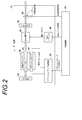
- FIG. 2 shows the configuration of the laser light source unit 13.
- the laser light source unit 13 includes a laser rod 31, a flash lamp 32, mirrors 33 and 34, a Q switch 35, a flash lamp power supply unit 37, a Q switch driver 38, and an optical path breaker 39.
- the laser rod 31 is a laser medium.
- an alexandrite crystal can be used.
- the flash lamp 32 is excitation means and irradiates the laser rod 31 with excitation light.
- the laser rod 31 and the flash lamp 32 are accommodated in the excitation chamber 36.
- the excitation chamber 36 is provided with cooling equipment and the like, and the temperature of the excitation chamber 36 is kept constant.
- the mirrors 33 and 34 are opposed to each other with the laser rod 31 in between, and the mirrors 33 and 34 constitute an optical resonator. Assume that the mirror 34 is on the output side.
- a Q switch 35 is inserted in the optical resonator.
- the Q switch 35 includes, for example, a Pockels cell.
- As the Q switch 35 for example, Impact10 manufactured by Gooch & Housego or Q1059 manufactured by Fast Pulse Technology can be used.
- the Q switch 35 changes the optical loss of the optical resonator according to the applied voltage. By rapidly changing the insertion loss in the optical resonator from a large loss (low Q) to a small loss (high Q) by the Q switch 35, a pulsed laser beam can be obtained.
- the Q switch 35 makes the insertion loss in the optical resonator large when a high voltage is applied, and makes the insertion loss in the optical resonator small when no voltage is applied.
- the optical loss of the optical resonator when the applied voltage is the first voltage is larger than the optical loss of the optical resonator when the applied voltage to the Q switch is the second voltage lower than the first voltage.
- the first voltage is a voltage of about 3 kV, for example, and the second voltage is 0 V (no voltage), for example.
- the Q switch (Pockels cell) 35 gives a predetermined phase difference between the polarized light component parallel to the optical axis of the transmitted light and the polarized light component perpendicular to the optical axis of the transmitted light when the applied voltage is the first voltage.
- the predetermined phase difference is, for example, ⁇ / 2.
- the Q switch 35 functions as a 1 ⁇ 4 wavelength plate with respect to the light having the wavelength of the laser light.
- the Q switch 35 does not give a phase difference between the polarization component parallel to the optical axis of the transmitted light and the polarization component perpendicular to the optical component. That is, the light is transmitted without changing the polarization state.
- the applied voltage is the first voltage, it corresponds to turning off the Q switch, and when the applied voltage is the second voltage, it corresponds to turning on the Q switch.
- the Q switch 35 only needs to increase the optical loss in the optical resonator to the extent that laser oscillation does not occur when the first voltage is applied.
- the Q switch 35 It is not limited to functioning as a quarter wave plate. Further, it is only necessary to reduce the optical loss in the optical resonator to such an extent that laser oscillation occurs when the second voltage is applied, and the Q switch 35 does not change the polarization state when the second voltage is applied. However, it is not limited to transmitting light. From the viewpoint of obtaining pulsed laser light having a high output and a short pulse time width, the Q switch 35 functions as a quarter-wave plate when the first voltage is applied, and the Q switch 35 is activated when the second voltage is applied. It is preferable to transmit light without changing the polarization state.
- the flash lamp power supply unit 37 drives the flash lamp 32.
- the flash lamp power supply unit 37 applies a voltage between the electrodes of the flash lamp.
- the flash lamp power supply unit 37 applies a voltage of several kV to the trigger electrode of the flash lamp 32.
- the flash lamp 32 emits light when a high voltage is applied to the trigger electrode.
- the Q switch driver 38 applies a high voltage pulse to the Q switch 35 to control on / off of the Q switch. On / off of the Q switch is controlled by a Q switch trigger signal from the control circuit 23.
- the optical path breaker 39 is arranged in the optical path of the pulse laser beam emitted from the output side mirror 34.
- the optical path breaker 39 is between a closed state in which the pulse laser beam is blocked so that the light is not emitted toward the subject, and an open state in which the pulse laser beam is allowed to pass and the light is emitted toward the subject. It is controlled by. Opening and closing of the optical path breaker 39 is controlled by an optical path cutoff signal from the control circuit 23.
- the optical path breaker 39 may be a mechanical shutter or a combination of a polarizer and an electro-optic element.
- the operation modes of the laser light source unit 13 include a first operation mode in which laser emission is performed and a second operation mode in which laser emission is interrupted and waited.
- the control circuit 23 opens the optical path breaker 39 in the first operation mode.
- the control circuit 23 sends a flash lamp trigger signal to the flash lamp power supply unit 37 to turn on the flash lamp 32.
- the Q switch driver 38 turns off the Q switch 35 by applying a voltage of about 3 kV to the Q switch before the flash lamp 32 is turned on.
- the control circuit 23 sends a Q switch trigger signal to the Q switch driver 38 after the flash lamp 32 is lit and the laser rod 31 is sufficiently excited.
- the Q switch driver 38 temporarily lowers the voltage applied to the Q switch 35 to 0 V in response to the Q switch trigger signal, and switches the Q switch 35 from OFF to ON.
- Laser oscillation occurs when the insertion loss in the optical resonator is switched from large loss to small loss, and pulse laser light is emitted from the output-side mirror 34.
- the control circuit 23 closes the optical path interrupter 39 through the optical path interrupt signal.
- the control circuit 23 controls the voltage applied from the Q switch driver 38 to the Q switch 35 to 0 V through the Q switch trigger signal.
- the Q switch 35 maintains the on state when the applied voltage is maintained at 0V.
- the control circuit 23 periodically sends a flash lamp trigger signal to the flash lamp power source 37, and the flash lamp 32 continues to be lit.
- the Q switch 35 is turned on when the flash lamp 32 is lit, so that laser oscillation occurs in the optical resonator, and a long pulse laser with a long pulse time width compared to when Q switch oscillation is performed. Light is emitted. This long pulse laser beam is blocked by the optical path breaker 39 and is not irradiated to the subject.
- FIG. 3 shows the operation waveforms of each part.
- the laser light source unit 13 When a doctor or the like instructs to generate a photoacoustic image (photoacoustic signal measurement) by operating the console, the laser light source unit 13 operates in the first operation mode. Before the flash lamp 32 emits light, a voltage of about 3 kV is stored in the capacitor of the trigger circuit included in the flash lamp power supply unit 37 (a). A high voltage of about 3 kV is applied to the Q switch 35, and the Q switch is off (c). The optical path breaker 39 is kept open (d).
- the control circuit 23 outputs a flash lamp trigger signal to the flash lamp power supply unit 37.
- the flash lamp power supply unit 37 supplies the voltage charged in the capacitor to the trigger electrode of the flash lamp 32.
- a high voltage is applied to the trigger electrode, discharge occurs in the flash lamp 32, and the flash lamp 32 emits light instantaneously (b).
- charging of the capacitor of the trigger circuit is started, and the capacitor is charged again to a voltage of about 3 kV.
- the control circuit 23 outputs the Q switch trigger signal to the Q switch driver 38 (c) after outputting the flash lamp trigger signal, for example, several hundreds of microseconds after the output of the flash lamp trigger signal.
- the Q switch driver 38 reduces the voltage applied to the Q switch 35 to 0 V for a predetermined period and turns on the Q switch 35.
- the Q switch 35 is switched from OFF to ON, the energy stored in the optical resonator oscillates at once, and a steep pulse laser beam having a pulse time width of about several nanoseconds to about 100 nanoseconds is emitted (e ).
- the Q switch driver 38 After the emission of the pulse laser beam, the Q switch driver 38 returns the applied voltage to the Q switch 35 to 3 kV (c), and turns the Q switch 35 off.
- the operation mode of the laser light source unit 13 is changed from the first operation mode to the second operation mode. Can be switched.
- the control circuit 23 closes the optical path interrupter 39 through the optical path cutoff signal (d). Further, the voltage applied from the Q switch driver 38 to the Q switch is switched to 0 V through the Q switch trigger signal (c). In the first operation mode, the voltage applied to the Q switch 35 is maintained at 0V.
- the control circuit 23 outputs a flash lamp trigger signal to the flash lamp power supply unit 37.
- the flash lamp power supply unit 37 supplies the voltage charged in the capacitor to the trigger electrode of the flash lamp 32.
- a high voltage is applied to the trigger electrode, discharge occurs in the flash lamp 32, and the flash lamp 32 emits light instantaneously (b). This operation is the same as the operation in the first operation mode.
- the Q switch when the applied voltage to the Q switch is the first high voltage, the Q switch is turned off, and when the applied voltage to the Q switch is the second low voltage, the Q switch It corresponds to ON. According to this configuration, when the applied voltage to the Q switch is high, the Q switch is turned on, and when the applied voltage to the Q switch is low (0 V), the Q switch is turned off. In the case of the configuration, it is not necessary to arrange a quarter-wave plate that needs to be arranged in the optical resonator, and the configuration in the optical resonator can be simplified.
- the voltage applied to the Q switch 35 is controlled to the low second voltage with the optical path breaker 39 closed.
- the applied voltage is the second voltage
- the Q switch 35 is on, and when the flash lamp 32 emits light, laser oscillation occurs in the optical resonator.
- this laser beam is blocked by the optical path breaker 39, it is not emitted to the outside. Therefore, it is not necessary to stop the excitation by the flash lamp 32.
- the voltage applied to the Q switch is the second low voltage during the second operation mode, it is possible to prevent a high voltage from being continuously applied to the Q switch during standby, Deterioration can be prevented.
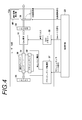
- FIG. 4 shows a laser light source unit in the photoacoustic measuring apparatus according to the second embodiment of the present invention.
- the laser light source unit 13a in this embodiment includes a circuit breaker closing detector 40 in addition to the configuration of the laser light source unit 13 in the first embodiment shown in FIG.
- the breaker closing detector 40 detects that the optical path breaker 39 is closed.
- the laser light source unit 13a When the breaker close detector 40 detects that the optical path breaker 39 is closed, the laser light source unit 13a operates in the second operation mode. More specifically, for example, the control circuit 23 closes the optical path interrupter 39 by the optical path interrupting signal, and the circuit breaker closing detector 40 detects that the optical path interrupter 39 is closed, and then the Q switch 35 through the Q switch trigger signal. The applied voltage is changed to 0V. By doing this, before closing the optical path breaker 39, the applied voltage to the Q switch 35 is set to 0V, the flash lamp 32 is turned on, and the long pulse laser light can be prevented from being emitted to the outside. The sex can be increased.
- the control circuit 23 closes the optical path breaker 39 in order to shift the operation mode to the second operation mode when, for example, a doctor or the like operates the console to stop the generation of the photoacoustic image. After detecting that the optical path breaker 39 is closed, the control circuit 23 controls the voltage applied to the Q switch 35 to 0V. Alternatively, after a doctor or the like operates the console to instruct to close the optical path interrupter 39 and detects that the optical path interrupter 39 is closed, the control circuit 23 determines the voltage applied to the Q switch 35. By controlling to 0V, the operation mode may be shifted to the second operation mode.
- the flash lamp 32 is used as the excitation means, but the excitation means is not limited to this.
- a light source other than the flash lamp 32 may be used as the excitation light source.
- wavelength selection means for controlling the oscillation wavelength may be inserted into the optical resonator, and the laser light source unit 13 may be configured as a variable wavelength laser that emits light with a plurality of wavelengths switched. .
- the laser light source unit 132 is operated in the second operation mode when a doctor or the like stops generating the photoacoustic image, but the present invention is not limited to this.
- the ultrasound unit 12 has three operation modes for image generation, that is, generation of only an ultrasound image, generation of only a photoacoustic image, and generation of both a photoacoustic image and an ultrasound image
- the ultrasound unit 12 may be operated in the second operation mode when operating in an operation mode in which a photoacoustic image is not included in an image generated by.
- the laser light source unit 13 may be operated in the second operation mode when there is no operation of the probe 11 or the console of the ultrasonic unit 12 for a certain time or longer.
- the photoacoustic measurement device and the laser light source of the present invention are not limited to the above embodiment, and various modifications can be made from the configuration of the above embodiment. Further, modifications and changes are also included in the scope of the present invention.
Landscapes
- Physics & Mathematics (AREA)
- Electromagnetism (AREA)
- Health & Medical Sciences (AREA)
- Life Sciences & Earth Sciences (AREA)
- Optics & Photonics (AREA)
- Engineering & Computer Science (AREA)
- General Health & Medical Sciences (AREA)
- Pathology (AREA)
- Plasma & Fusion (AREA)
- General Physics & Mathematics (AREA)
- Chemical & Material Sciences (AREA)
- Biochemistry (AREA)
- Immunology (AREA)
- Analytical Chemistry (AREA)
- Acoustics & Sound (AREA)
- Biophysics (AREA)
- Surgery (AREA)
- Veterinary Medicine (AREA)
- Biomedical Technology (AREA)
- Heart & Thoracic Surgery (AREA)
- Medical Informatics (AREA)
- Molecular Biology (AREA)
- Public Health (AREA)
- Animal Behavior & Ethology (AREA)
- Crystallography & Structural Chemistry (AREA)
- Signal Processing (AREA)
- Ultra Sonic Daignosis Equipment (AREA)
- Investigating Or Analyzing Materials By The Use Of Ultrasonic Waves (AREA)
- Lasers (AREA)
Abstract
本発明は、光共振器の構成を簡素化でき、かつ、光出射を行わない待機時間が長い場合でもQスイッチの劣化を抑制可能な光音響計測装置及びレーザ光源を提供する。フラッシュランプ32は、レーザロッド31を励起する。光共振器を構成する一対のミラー33、34の光路上に、印加電圧に応じて光共振器の損失を変化させるQスイッチ35が挿入される。光路遮断器39は、レーザ出射光の光路上に配置される。レーザ出射を行う第1の動作モード時は、光路遮断器39が開かれた状態であって、かつフラッシュランプ32によるレーザロッド31の励起後に、Qスイッチ35への印加電圧を高電圧から例えば0Vに変化させることによりパルスレーザ光の出射を行う。レーザ出射を中断して待機する第2の動作モード時は、光路遮断器39が閉じられた状態で、Qスイッチ35への印加電圧を例えば0Vにする。
Description
本発明は、光音響計測装置に関し、更に詳しくは、被検体に対する光出射後に被検体内で発生した光音響波を検出する光音響計測装置に関する。また、本発明は、そのような光音響計測装置に用いられるレーザ光源に関する。
生体内部の状態を非侵襲で検査できる画像検査法の一種として、超音波検査法が知られている。超音波検査では、超音波の送信及び受信が可能なプローブ(探触子)を用いる。プローブから被検体(生体)に超音波を送信させると、その超音波は生体内部を進んでいき、組織界面で反射する。プローブでその反射音波を受信し、反射超音波がプローブに戻ってくるまでの時間に基づいて距離を計算することで、内部の様子を画像化することができる。
また、光音響効果を利用して生体の内部を画像化する光音響イメージングが知られている。一般に光音響イメージングでは、パルスレーザ光を生体内に照射する。生体内部では、生体組織がパルスレーザ光のエネルギーを吸収し、そのエネルギーによる断熱膨張により超音波(光音響信号)が発生する。この光音響信号をプローブなどで検出し、検出信号に基づいて光音響画像を構成することで、光音響信号に基づく生体内の可視化が可能である。
光音響イメージングでは、パルスレーザ光を出射する光源として、Qスイッチレーザが用いられることが多い。Qスイッチレーザでは、光共振器の中に光損失を制御するためのQスイッチが配置される。Qスイッチには、例えばポッケルスセルが用いられる。レーザ媒質が十分に励起されるまでは、Qスイッチをオフにして光共振器内の損失を大きくし、発振を抑える。レーザ媒質が十分に励起された後にQスイッチをオフからオンに切り替えると、十分に蓄えられていたエネルギーが一度に発振し、非常に強い、短いパルス幅のジャイアントパルスが得られる。Qスイッチは、パルスレーザの出射後、オフに戻される。
Qスイッチレーザを用いた光音響画像生成装置は、例えば特許文献1に記載されている。特許文献1では、遮光のための外装カバーの中に、被検体を圧迫するためのプレートと、光音響波を検出する検出器と、光源であるQスイッチレーザとが配置されている。外装カバーには手技用ドアが設けられており、医師などの術者は、手技用ドアから手を入れて被検体をプレートに挟む。被検体をプレートに挟んだ後に被検体に対する光照射を行い、被検体内で発生した光音響波を検出する。
特許文献1には、手技用ドアが開かれたときに、Qスイッチレーザの発光を停止するか、レーザ光を遮光することも記載されている。制御部は、ドア開閉検知センサにより手技用ドアが開かれていることが検知されると、QスイッチレーザのQスイッチをオフにする。また、レーザ光の光路上に設けられたシャッタを閉じ、Qスイッチレーザから出射したレーザ光が被検体に照射されないようにする。特許文献1には、安全性をより一層向上させるという観点から、Qスイッチをオフにし、かつシャッタを閉じることが好ましいという記載もある。
特開2011-224205号公報
ここで、光音響画像生成装置の使用状況を考えると、長時間にわたって光音響画像を観察し続けることは少なく、手術の前後での使用など、光音響画像を短い時間観察した後にしばらく待機し、その後また短い時間光音響画像を観察するといった使われ方が多いと考えられる。光音響画像の生成を行わずに待機している間は、レーザ光源からレーザ光を出射する必要はない。しかし、励起を停止するとレーザロッドの温度が変化して発光条件が変化することがあるため、待機している間もフラッシュランプなどの点灯を継続して行い、レーザ媒質を周期的に励起しておくことが好ましい。励起を停止しないことで、レーザ媒質の温度を一定に保つことができる。このときQスイッチをオフに保てば、外部へのレーザ光出力を防ぐことができる。
ところで、Qスイッチの使用形態には、Qスイッチが1/4波長板として機能するときがオンで、偏光状態を変化させずに光を透過させるときをオフとする形態(第1の形態)と、1/4波長板として機能するときがオフで、偏光状態を変化させずに光を透過させるときをオンとする形態(第2の形態)とがある。第1の形態では、励起が完了するまではQスイッチへは電圧印加を行わず、パルスレーザ光の出射のタイミングで、Qスイッチに例えば3kV程度の高電圧パルスを印加する。印加電圧の大きさは、使用するポッケルスセルの材質と波長とによって決まる。一方、第2の形態では、励起が完了するまでQスイッチに3kV程度の高電圧を印加し続け、パルスレーザ光の出射のタイミングで、Qスイッチへの印加電圧を無電圧まで落とす(ネガティブパルス)。
上記第1の形態では、Qスイッチへの印加電圧が無電圧の場合にQスイッチがオフであるため、励起を継続しつつ待機する場合に、Qスイッチへ高電圧を印加し続ける必要はない。しかし、Qスイッチが偏光状態を変化させずに光を透過するときに光共振器の光損失を大きくするために、光共振器内に別途1/4波長板を配置する必要がある。これに対し、第2の形態では、光共振器内に1/4波長板を配置する必要はなく、光共振器の構成を簡素化することができ、装置の小型化やコスト低減が可能である。しかし、第2の形態では、Qスイッチをオフにしたままで励起だけ行う場合に、Qスイッチに高電圧を印加し続ける必要がある。Qスイッチに高電圧を印加し続けると、Qスイッチの劣化につながるという問題がある。
特許文献1は、手技用ドアが開かれたときにレーザの発光を停止するためにQスイッチをオフにするものであり、上記第2の形態でQスイッチを使用するときは、Qスイッチに高電圧を印加し続ける必要がある。特許文献1には、シャッタを閉じてレーザ光を遮光することも記載されているが、このときQスイッチは通常のレーザ発光時と同様に制御される。従って、Qスイッチをオンにする短い時間を除けば、Qスイッチに高電圧を印加し続けなければならない。従って、特許文献1は、上記問題点を解消するための手段を持ち合わせていない。
本発明は、上記に鑑み、光共振器の構成を簡素化でき、かつ、光出射を行わない待機時間が長い場合でもQスイッチの劣化を抑制可能な光音響計測装置及びレーザ光源を提供することを目的とする。
上記目的を達成するために、本発明は、レーザ光源と、レーザ光源からの光が被検体に出された後に、光出射に起因して発生した光音響波を検出する音響波検出手段と、光音響波を信号処理する光音響信号処理手段とを備え、レーザ光源が、レーザ媒質と、レーザ媒質を励起する励起手段と、レーザ媒質を挟んで対向する一対のミラーを含む光共振器と、光共振器の光路上に配置され、印加電圧に応じて光共振器の光損失を変化させるQスイッチであって、印加電圧が第1の電圧のときの光共振器の光損失を、Qスイッチへの印加電圧が第1の電圧よりも低い第2の電圧のときの光共振器の光損失よりも大きくするQスイッチと、レーザ出射光の光路上に配置され、レーザ出射光の通過及び遮断を切り替える光路遮断器とを有し、レーザ出射を行う第1の動作モード時は、光路遮断器がレーザ光源からの光を通過する状態であって、かつ励起手段によるレーザ媒質の励起後に、Qスイッチへの印加電圧を第1の電圧から第2の電圧に変化させることによりパルスレーザ光の出射を行い、レーザ出射を中断して待機する第2の動作モード時は、光路遮断器がレーザ光源からの光を遮断する状態において、Qスイッチへの印加電圧を第2の電圧とすることを特徴とする光音響計測装置を提供することを目的とする。
本発明の光音響計測装置において、第2の動作モードで動作するときに、励起手段が周期的にレーザ媒質の励起を行ってもよい。
第2の電圧は0Vであってもよい。
Qスイッチは、印加電圧が第1の電圧のとき透過光の光学軸に平行な偏光成分と垂直な偏光成分との間に所定の位相差を与え、かつ印加電圧が第2の電圧のときは透過光の光学軸に平行な偏光成分と垂直な偏光成分との間に位相差を与えないものであってよい。
Qスイッチは、印加電圧が第1の電圧のときレーザ光の波長の光に対して1/4波長板として機能するものとしてもよい。
光音響信号処理手段は、光音響信号に基づいて光音響画像を生成してもよい。
レーザ光源が、光路遮断器が閉じられていることを検出する遮断器閉検出器を更に有する構成を採用でき、その場合、遮断器閉検出器によって光路遮断器が閉じられていることが検出されるとQスイッチへの印加電圧が第2の電圧に制御されてもよい。
光音響信号の計測が指示されると第1の動作モードで動作し、光音響信号の計測停止が指示されると、第2の動作モードで動作することとしてもよい。
本発明は、また、レーザ媒質と、レーザ媒質を励起する励起手段と、レーザ媒質を挟んで対向する一対のミラーを含む光共振器と、光共振器の光路上に配置され、印加電圧に応じて光共振器の光損失を変化させるQスイッチであって、印加電圧が第1の電圧のときの光共振器の光損失を、Qスイッチへの印加電圧が第1の電圧よりも低い第2の電圧のときの光共振器の光損失よりも大きくするQスイッチと、レーザ出射光の光路上に配置され、レーザ出射光の通過及び遮断を切り替える光路遮断器とを有し、レーザ出射を行う第1の動作モード時は、光路遮断器がレーザ光源からの光が通過する状態であって、かつ励起手段によるレーザ媒質の励起後に、Qスイッチへの印加電圧を第1の電圧から第2の電圧に変化させることによりパルスレーザ光の出射を行い、レーザ出射を中断して待機する第2の動作モード時は、光路遮断器がレーザ光源からの光を遮断する状態において、Qスイッチへの印加電圧を第2の電圧とすることを特徴とするレーザ光源を提供する。
本発明の光音響計測装置では、共振器に挿入されたQスイッチは、高電圧である第1の電圧の電圧が印加されているときは光共振器の光損失を損失大とし、低電圧である第2の電圧の電圧が印加されているときに光共振器の光損失を損失小とする。レーザ出射光の光路上には光路遮断器が設けられている。レーザ出射を中断して待機する第2の動作モード時は、光路遮断器が閉じられた状態において、Qスイッチへの印加電圧を低電圧の第2の電圧とする。第2の動作モード時は、Qスイッチへの印加電圧が低電圧の第2の電圧であるために、励起手段がレーザ媒質を励起すると光共振器ではQスイッチ発振に比べて弱いレーザ発振が起こる。しかし、光路遮断器を閉じておくことにより、その発振光が光路遮断器よりも先に出射されることが防止される。このようにすることにより、光出射を行わない待機時間が長い場合でも光出射を抑えるためにQスイッチに高電圧を印加し続ける必要がなく、Qスイッチの劣化を抑制できる。また、光共振器内に別途1/4波長板を配置する必要がないことから光共振器の構成を簡素化できる。
以下、図面を参照し、本発明の実施の形態を詳細に説明する。図1は、本発明の第1実施形態の光音響計測装置を示す。光音響計測装置10は、超音波探触子(プローブ)11と、超音波ユニット12と、レーザ光源ユニット13とを備える。なお、本発明の実施形態では、光音響波として超音波を用いるが、超音波に限定されるものでは無く、被検対象や測定条件等に応じて適切な周波数を選択してさえいれば、可聴周波数の音響波を用いても良い。
レーザ光源ユニット13は、被検体に照射すべきパルスレーザ光を出射する。レーザ光源ユニット13から出射したレーザ光は、例えば光ファイバなどの導光手段を用いてプローブ11まで導光され、プローブ11から被検体に向けて照射される。レーザ光の照射位置は特に限定されず、プローブ11以外の場所からレーザ光の照射を行ってもよい。被検体内では、光吸収体が照射されたレーザ光のエネルギーを吸収することで超音波(光音響波)が生じる。
プローブ11は、超音波検出器を含む。プローブ11は、例えば一次元的に配列された複数の超音波検出器素子(超音波振動子)を有し、その一次元配列された超音波振動子により、被検体内からの光音響波を検出する。プローブ11が、更に、被検体に対する超音波の送信を行い、送信された超音波に対する反射超音波を検出することとしてもよい。
超音波ユニット12は、受信回路21、光音響画像生成手段22、及び制御回路23を有する。受信回路21は、プローブ11が検出した光音響波の検出信号(光音響信号)を受信する。光音響画像生成手段22は、信号処理手段であり、受信された光音響信号に基づいて光音響画像を生成する。光音響画像の生成は、光音響信号の再構成、検波・対数変換などの処理を含む。超音波ユニット12が、プローブ11で検出された反射超音波の検出信号(反射超音波信号)に基づいて超音波画像を生成する超音波画像生成手段を更に備えていてもよい。
なお、超音波ユニット12において画像の生成は必須ではなく、光音響画像生成手段22が、光音響信号に対して何らかの信号処理を施すだけでもよい。また、超音波画像生成手段が、反射超音波信号に対して何らかの信号処理を施すだけでもよい。
制御回路23は、制御手段であり、超音波ユニット12内の各部を制御する。また、レーザ光源ユニット13に制御信号を送り、レーザ出射などを制御する。より詳細には、制御回路23は、レーザ光源ユニット13に対してフラッシュランプトリガ信号、Qスイッチトリガ信号、及び光路遮断信号を出力する。
図2は、レーザ光源ユニット13の構成を示す。レーザ光源ユニット13は、レーザロッド31、フラッシュランプ32、ミラー33、34、Qスイッチ35、フラッシュランプ電源部37、Qスイッチドライバ38、及び光路遮断器39を有する。レーザロッド31は、レーザ媒質である。レーザロッド31には、例えばアレキサンドライト結晶を用いることができる。フラッシュランプ32は、励起手段であり、レーザロッド31に励起光を照射する。レーザロッド31及びフラッシュランプ32は励起チャンバ36に収容される。励起チャンバ36には冷却設備等が備えられており、励起チャンバ36の温度は一定に保たれる。
ミラー33、34は、レーザロッド31を挟んで対向しており、ミラー33、34により光共振器が構成される。ミラー34が出力側であるものとする。光共振器内には、Qスイッチ35が挿入される。Qスイッチ35は、例えばポッケルスセルを含む。Qスイッチ35には、例えばGooch & Housego社製のImpact10や、Fast Pulse Technology社製のQ1059を用いることができる。Qスイッチ35は、印加電圧に応じて光共振器の光損失を変化させる。Qスイッチ35により、光共振器内の挿入損失を損失大(低Q)から損失小(高Q)へと急速に変化させることで、パルスレーザ光を得ることができる
Qスイッチ35は、高電圧が印加されているときは光共振器内の挿入損失を損失大とし、無電圧状態のときは光共振器内の挿入損失を損失小とする。換言すれば、印加電圧が第1の電圧のときの光共振器の光損失は、Qスイッチへの印加電圧が第1の電圧よりも低い第2の電圧のときの光共振器の光損失よりも大きい。第1の電圧は例えば3kV程度の電圧であり、第2の電圧は例えば0V(無電圧)である。
Qスイッチ(ポッケルスセル)35は、印加電圧が第1の電圧のとき、透過光の光学軸に平行な偏光成分と垂直な偏光成分との間に所定の位相差を与える。所定の位相差は例えばπ/2であり、このときQスイッチ35は、レーザ光の波長の光に対して1/4波長板として機能する。Qスイッチ35は、印加電圧が第2の電圧のときは、透過光の光学軸に平行な偏光成分と垂直な偏光成分との間に位相差を与えない。つまり、偏光状態を変化させずに透過する。印加電圧が第1の電圧のときがQスイッチのオフに対応し、印加電圧が第2の電圧のときがQスイッチのオンに対応する。
なお、Qスイッチ35は、第1の電圧の電圧が印加されたときにレーザ発振を起こさせない程度に光共振器内の光損失を大きくすればよく、第1の電圧の印加時にQスイッチ35が1/4波長板として機能することには限定されない。また、第2の電圧の電圧が印加されたときにレーザ発振が起こる程度の光共振器内の光損失を小さくすればよく、第2の電圧の印加時にQスイッチ35が偏光状態を変化させずに光を透過させることには限定されない。高出力及びパルス時間幅が短いパルスレーザ光を得るという観点からは、第1の電圧の印加時にQスイッチ35が1/4波長板として機能し、かつ第2の電圧の印加時にQスイッチ35が偏光状態を変化させずに光を透過させることが好ましい。
フラッシュランプ電源部37は、フラッシュランプ32を駆動する。フラッシュランプ電源部37は、フラッシュランプの電極間に電圧を印加する。フラッシュランプ電源部37は、制御回路23からフラッシュランプトリガ信号を受け取ると、フラッシュランプ32のトリガ電極に数kVの電圧を印加する。トリガ電極に高電圧が印加されることで、フラッシュランプ32が発光する。
Qスイッチドライバ38は、Qスイッチ35に高電圧パルスを印加し、Qスイッチのオン・オフを制御する。Qスイッチのオン・オフは、制御回路23からのQスイッチトリガ信号により制御される。
光路遮断器39は、出力側のミラー34から出射したパルスレーザ光の光路に配置される。光路遮断器39は、パルスレーザ光を遮断して被検体に向けて光が出射されないようにする閉状態と、パルスレーザ光を通過させて被検体に向けて光を出射させる開状態との間で制御される。光路遮断器39の開閉は、制御回路23からの光路遮断信号により制御される。光路遮断器39は、メカニカルなシャッタでもよいし、偏光子と電気光学素子を組み合わせたものでもよい。
ここで、レーザ光源ユニット13(光音響計測装置10)の動作モードは、レーザ出射を行う第1の動作モードと、レーザ出射を中断して待機する第2の動作モードとを含む。制御回路23は、第1の動作モード時は光路遮断器39を開く。制御回路23は、フラッシュランプトリガ信号をフラッシュランプ電源部37に送り、フラッシュランプ32を点灯させる。Qスイッチドライバ38は、フラッシュランプ32の点灯前はQスイッチに3kV程度の電圧を印加してQスイッチ35をオフにしている。制御回路23は、フラッシュランプ32の点灯後、レーザロッド31が十分に励起された後にQスイッチドライバ38にQスイッチトリガ信号を送る。Qスイッチドライバ38は、Qスイッチトリガ信号に応答してQスイッチ35の印加電圧を一時的に0Vまで下げ、Qスイッチ35をオフからオンに切り替える。光共振器内の挿入損失が損失大から損失小に切り替わることでレーザ発振が起き、出力側のミラー34からパルスレーザ光が出射する。
制御回路23は、第2の動作モード時は、光路遮断信号を通じて光路遮断器39を閉じる。また、制御回路23は、Qスイッチトリガ信号を通じてQスイッチドライバ38からQスイッチ35へ印加する電圧を0Vに制御する。Qスイッチ35は、印加電圧が0Vに保たれることでオンの状態を維持する。このとき、制御回路23は、フラッシュランプ電源部37にフラッシュランプトリガ信号を周期的に送り、フラッシュランプ32の点灯は継続する。フラッシュランプ32が点灯すると、Qスイッチ35はフラッシュランプ32の点灯時にオンであるため、光共振器ではレーザ発振が起こり、Qスイッチ発振を行ったときに比べてパルス時間幅が長いロングパルスのレーザ光が出射する。このロングパルスのレーザ光は光路遮断器39で遮断され、被検体には照射されない。
図3は、各部の動作波形を示す。医師などがコンソールを操作するなどにより光音響画像の生成(光音響信号の計測)を指示するとき、レーザ光源ユニット13は第1の動作モードで動作する。フラッシュランプ32の発光前、フラッシュランプ電源部37に含まれるトリガ回路のコンデンサは3kV程度の電圧が蓄えられている(a)。また、Qスイッチ35には3kV程度の高電圧が印加されており、Qスイッチはオフしている(c)。光路遮断器39は開状態に維持される(d)。
制御回路23は、フラッシュランプ電源部37にフラッシュランプトリガ信号を出力する。フラッシュランプ電源部37は、制御回路23からフラッシュランプトリガ信号を受け取ると、コンデンサに充電された電圧をフラッシュランプ32のトリガ電極に供給する。トリガ電極に高電圧が印加されると、フラッシュランプ32の中で放電が発生し、フラッシュランプ32が瞬間的に発光する(b)。フラッシュランプ32の発光後、トリガ回路のコンデンサへの充電が開始され、コンデンサは、再び3kV程度の電圧まで充電される。
制御回路23は、フラッシュランプトリガ信号の出力後、例えばフラッシュランプトリガ信号を出力してから数100μ秒後に、Qスイッチドライバ38にQスイッチトリガ信号を出力する(c)。Qスイッチドライバ38は、Qスイッチトリガ信号に応答して、所定の期間だけQスイッチ35への印加電圧を0Vまで下げ、Qスイッチ35をオンにする。Qスイッチ35がオフからオンに切り替わると、光共振器内に蓄えられていたエネルギーが一度に発振し、パルス時間幅が数n秒から100n秒程度の急峻なパルスレーザ光が出射される(e)。パルスレーザ光の出射後、Qスイッチドライバ38は、Qスイッチ35への印加電圧を3kVに戻し(c)、Qスイッチ35をオフに戻す。
医師などがコンソールを操作するなどにより、光音響画像の生成(光音響信号の計測)を停止する旨を指示すると、レーザ光源ユニット13の動作モードは第1の動作モードから第2の動作モードに切り替えられる。動作モードが第1の動作モードから第2の動作モードに切り替えられると、制御回路23は、光路遮断信号を通じて光路遮断器39を閉にする(d)。また、Qスイッチトリガ信号を通じて、Qスイッチドライバ38からQスイッチに印加する電圧を0Vに切り替える(c)。第1の動作モードでは、Qスイッチ35への印加電圧は0Vに維持される。
制御回路23は、フラッシュランプ電源部37にフラッシュランプトリガ信号を出力する。フラッシュランプ電源部37は、制御回路23からフラッシュランプトリガ信号を受け取ると、コンデンサに充電された電圧をフラッシュランプ32のトリガ電極に供給する。トリガ電極に高電圧が印加されると、フラッシュランプ32の中で放電が発生し、フラッシュランプ32が瞬間的に発光する(b)。この動作は、第1の動作モードにおける動作と同様である。
フラッシュランプ32が発光するとき、Qスイッチ35はオンであるため、レーザ発振が起こる。ただし、このときのレーザ発振は、レーザ媒質の励起後すぐに起こるため、第1の動作モードにおけるQスイッチレーザ発振と比べて弱い発振となる。出力側のミラー34からは、Qスイッチレーザ発振の場合に比べてパルス時間幅が長いロングパルスのレーザ光が出射する。このロングパルスのレーザ光は、閉状態の光路遮断器39で遮断され、外部には出力されない(e)。
本実施形態では、Qスイッチへの印加電圧が高電圧の第1の電圧のときがQスイッチのオフに対応し、Qスイッチへの印加電圧が低電圧の第2の電圧のときがQスイッチのオンに対応している。この構成によれば、Qスイッチへの印加電圧が高電圧のときがQスイッチのオンに対応し、Qスイッチへの印加電圧が低電圧(0V)のときがQスイッチのオフに対応している構成の場合に光共振器内に配置する必要がある1/4波長板の配置が不要であり、光共振器内の構成を簡素化できる。
本実施形態では、レーザ出射を行わずに待機する第2の動作モード時は、光路遮断器39が閉じられた状態で、Qスイッチ35への印加電圧が低電圧の第2の電圧に制御される。印加電圧が第2の電圧のときQスイッチ35はオンであり、フラッシュランプ32を発光すると、光共振器ではレーザ発振が起こる。しかし、このレーザ光は光路遮断器39で遮断されるため、外部には出射されない。従って、フラッシュランプ32による励起を停止する必要はない。本実施形態では、第2の動作モード時はQスイッチへの印加電圧を低電圧の第2の電圧にしているため、待機時にQスイッチに高電圧が印加され続けることを防止でき、Qスイッチの劣化を防止できる。
続いて、本発明の第2実施形態を説明する。図4は、本発明の第2実施形態の光音響計測装置におけるレーザ光源ユニットを示す。本実施形態におけるレーザ光源ユニット13aは、図2に示す第1実施形態におけるレーザ光源ユニット13の構成に加えて、遮断器閉検出器40を備える。遮断器閉検出器40は、光路遮断器39が閉じられていることを検出する。
遮断器閉検出器40が、光路遮断器39が閉じていることを検出するとき、レーザ光源ユニット13aは、第2の動作モードで動作する。より詳細には、例えば制御回路23は、光路遮断信号によって光路遮断器39を閉じ、遮断器閉検出器40が、光路遮断器39が閉じたことを検出した後にQスイッチトリガ信号を通じてQスイッチ35への印加電圧を0Vに変更させる。このようにすることで、光路遮断器39を閉じる前に、Qスイッチ35への印加電圧を0Vにし、フラッシュランプ32を点灯してロングパルスのレーザ光が外部に出射することを防止でき、安全性をより高めることができる。
制御回路23は、例えば医師などがコンソールを操作することにより光音響画像の生成の停止する指示すると、動作モードを第2の動作モードに移行させるために光路遮断器39を閉じる。光路遮断器39が閉じたことが検出された後に、制御回路23は、Qスイッチ35への印加電圧を0Vに制御する。あるいは、医師などがコンソールを操作することにより光路遮断器39を閉じることを指示し、光路遮断器39が閉じられたことが検出された後に、制御回路23は、Qスイッチ35への印加電圧を0Vに制御することで、動作モードを第2の動作モードに移行させてもよい。
なお、図2では、励起手段としてフラッシュランプ32を用いているが、励起手段はこれには限定されない。フラッシュランプ32以外の光源を、励起光源として用いてもよい。また、図2において、光共振器の中に発振波長を制御するための波長選択手段を挿入し、レーザ光源ユニット13を、複数波長の光を切り替えて出射する可変波長レーザとして構成してもよい。
上記実施形態では、医師などが光音響画像の生成を停止するとレーザ光源ユニット132を第2の動作モードで動作させるものとして説明したが、本発明は、これには限定されない。例えば超音波ユニット12が、画像生成に関して、超音波画像のみの生成、光音響画像のみの生成、光音響画像と超音波画像の双方の生成との3つの動作モードを持つとき、超音波ユニット12が生成する画像に光音響画像が含まれない動作モードで動作するときに、レーザ光源ユニット13を第2の動作モードで動作させることとしてもよい。あるいは、プローブ11や超音波ユニット12のコンソールなどの操作が一定時間以上ない場合に、レーザ光源ユニット13を第2の動作モードで動作させてもよい。
以上、本発明をその好適な実施形態に基づいて説明したが、本発明の光音響計測装置及びレーザ光源は、上記実施形態にのみ限定されるものではなく、上記実施形態の構成から種々の修正及び変更を施したものも、本発明の範囲に含まれる。
10:光音響計測装置
11:プローブ
12:超音波ユニット
13:レーザ光源ユニット
21:受信回路
22:光音響画像生成手段
23:制御回路
31:レーザロッド
32:フラッシュランプ
33、34:ミラー
35:Qスイッチ
36:励起チャンバ
37:フラッシュランプ電源部
38:Qスイッチドライバ
39:光路遮断器
40:遮断器閉検出器
11:プローブ
12:超音波ユニット
13:レーザ光源ユニット
21:受信回路
22:光音響画像生成手段
23:制御回路
31:レーザロッド
32:フラッシュランプ
33、34:ミラー
35:Qスイッチ
36:励起チャンバ
37:フラッシュランプ電源部
38:Qスイッチドライバ
39:光路遮断器
40:遮断器閉検出器
Claims (10)
- レーザ媒質と、
前記レーザ媒質を励起する励起手段と、
前記レーザ媒質を挟んで対向する一対のミラーを含む光共振器と、
前記光共振器の光路上に配置され、印加電圧に応じて前記光共振器の光損失を変化させるQスイッチであって、印加電圧が第1の電圧のときの前記光共振器の光損失を、前記Qスイッチへの印加電圧が前記第1の電圧よりも低い第2の電圧のときの前記光共振器の光損失よりも大きくするQスイッチと、
レーザ出射光の光路上に配置され、レーザ出射光の通過及び遮断を切り替える光路遮断器とを有するレーザ光源と、
前記レーザ光源からの光が被検体に出射された後に、該光出射に起因して発生した光音響波を検出する音響波検出手段と、
前記光音響波を信号処理する光音響信号処理手段と、
レーザ出射を行う第1の動作モード時は、前記光路遮断器が前記レーザ光源からの光を通過する状態であって、かつ前記励起手段によるレーザ媒質の励起後に、前記Qスイッチへの印加電圧を前記第1の電圧から前記第2の電圧に変化させることによりパルスレーザ光の出射を行い、レーザ出射を中断して待機する第2の動作モード時は、前記光路遮断器が前記レーザ光源からの光を遮断する状態において、前記Qスイッチへの印加電圧を前記第2の電圧とする制御手段とを備える光音響計測装置。 - 前記第2の動作モードでは、前記励起手段が周期的にレーザ媒質の励起を行う請求項1に記載の光音響計測装置。
- 前記第2の電圧が0Vである請求項1又は2に記載の光音響計測装置。
- 前記Qスイッチが、印加電圧が第1の電圧のとき透過光の光学軸に平行な偏光成分と垂直な偏光成分との間に所定の位相差を与え、かつ印加電圧が前記第2の電圧のときは透過光の光学軸に平行な偏光成分と垂直な偏光成分との間に位相差を与えない請求項1から3何れか1項に記載の光音響計測装置。
- 前記Qスイッチが、印加電圧が第1の電圧のときレーザ光の波長の光に対して1/4波長板として機能する請求項1から4何れか1項に記載の光音響計測装置。
- 前記光音響信号処理手段が、前記光音響信号に基づいて光音響画像を生成する請求項1から5何れか1項に記載の光音響計測装置。
- 前記レーザ光源が、前記光路遮断器が閉じられていることを検出する遮断器閉検出器を更に有し、前記制御手段が、前記遮断器閉検出器によって前記光路遮断器が閉じられていることが検出されているときに、前記Qスイッチへの印加電圧を第2の電圧に制御する請求項1から6何れか1項に記載の光音響計測装置。
- 前記光音響信号の計測が指示されると前記第1の動作モードで動作し、前記光音響信号の計測停止が指示されると、前記第2の動作モードで動作する請求項1から7何れか1項に記載の光音響計測装置。
- 前記制御手段が、前記第1の動作モード時は、前記Qスイッチへの印加電圧を前記第1の電圧から前記第2の電圧に変化させた後に、前記Qスイッチへの印加電圧を前記第1の電圧とする請求項1から8何れか1項に記載の光音響計測装置。
- レーザ媒質と、
前記レーザ媒質を励起する励起手段と、
前記レーザ媒質を挟んで対向する一対のミラーを含む光共振器と、
前記光共振器の光路上に配置され、印加電圧に応じて前記光共振器の光損失を変化させるQスイッチであって、印加電圧が第1の電圧のときの前記光共振器の光損失を、前記Qスイッチへの印加電圧が前記第1の電圧よりも低い第2の電圧のときの前記光共振器の光損失よりも大きくするQスイッチと、
レーザ出射光の光路上に配置され、レーザ出射光の通過及び遮断を切り替える光路遮断器とを有し、
レーザ出射を行う第1の動作モード時は、前記光路遮断器が前記レーザ光源からの光を通過する状態であって、かつ前記励起手段によるレーザ媒質の励起後に、前記Qスイッチへの印加電圧を前記第1の電圧から前記第2の電圧に変化させることによりパルスレーザ光の出射を行い、
レーザ出射を中断して待機する第2の動作モード時は、前記光路遮断器が前記レーザ光源からの光を遮断する状態において、前記Qスイッチへの印加電圧を前記第2の電圧とするレーザ光源。
Priority Applications (2)
| Application Number | Priority Date | Filing Date | Title |
|---|---|---|---|
| US14/801,533 US9743840B2 (en) | 2013-03-25 | 2015-07-16 | Photoacoustic measurement device and laser light source |
| US15/655,097 US10105063B2 (en) | 2013-03-25 | 2017-07-20 | Photoacoustic measurement device and laser light source |
Applications Claiming Priority (2)
| Application Number | Priority Date | Filing Date | Title |
|---|---|---|---|
| JP2013061502A JP5938362B2 (ja) | 2013-03-25 | 2013-03-25 | 光音響計測装置及びレーザ装置 |
| JP2013-061502 | 2013-03-25 |
Related Child Applications (1)
| Application Number | Title | Priority Date | Filing Date |
|---|---|---|---|
| US14/801,533 Continuation US9743840B2 (en) | 2013-03-25 | 2015-07-16 | Photoacoustic measurement device and laser light source |
Publications (1)
| Publication Number | Publication Date |
|---|---|
| WO2014156749A1 true WO2014156749A1 (ja) | 2014-10-02 |
Family
ID=51623730
Family Applications (1)
| Application Number | Title | Priority Date | Filing Date |
|---|---|---|---|
| PCT/JP2014/057064 Ceased WO2014156749A1 (ja) | 2013-03-25 | 2014-03-17 | 光音響計測装置及びレーザ光源 |
Country Status (3)
| Country | Link |
|---|---|
| US (2) | US9743840B2 (ja) |
| JP (1) | JP5938362B2 (ja) |
| WO (1) | WO2014156749A1 (ja) |
Cited By (2)
| Publication number | Priority date | Publication date | Assignee | Title |
|---|---|---|---|---|
| WO2021068212A1 (zh) * | 2019-10-11 | 2021-04-15 | 深圳市大疆创新科技有限公司 | 一种光发射装置及测距装置、移动平台 |
| WO2023184602A1 (zh) * | 2022-03-29 | 2023-10-05 | 安徽理工大学 | 一种本安防爆型光声光谱粉尘检测装置 |
Families Citing this family (6)
| Publication number | Priority date | Publication date | Assignee | Title |
|---|---|---|---|---|
| JP6556509B2 (ja) * | 2015-06-16 | 2019-08-07 | Cyberdyne株式会社 | 光音響画像化装置および光源ユニット |
| WO2017169452A1 (ja) * | 2016-03-30 | 2017-10-05 | 富士フイルム株式会社 | レーザ装置および光音響計測装置 |
| US11973303B2 (en) * | 2021-06-28 | 2024-04-30 | Panasonic Intellectual Property Management Co., Ltd. | Laser apparatus having multiple-pass electro-optic modulators |
| CN114296387A (zh) * | 2021-12-22 | 2022-04-08 | 西南交通大学 | 一种激光器标定plc慢控系统 |
| US12316066B2 (en) * | 2022-01-27 | 2025-05-27 | Sciaps, Inc. | Dual beam single spatial mode laser for handheld libs instruments and similar applications |
| WO2024054856A1 (en) * | 2022-09-08 | 2024-03-14 | Femtometrix, Inc. | Method and apparatus for main detector synchronization of optically based second harmonic generation measurements |
Citations (4)
| Publication number | Priority date | Publication date | Assignee | Title |
|---|---|---|---|---|
| JPH04351280A (ja) * | 1990-12-26 | 1992-12-07 | Mid:Kk | 薄膜精密加工用のyagレーザ加工機 |
| JPH11224968A (ja) * | 1997-10-24 | 1999-08-17 | Coherent Luebeck Gmbh | 第1パルス制御を有するパルスレーザ |
| JP2003017787A (ja) * | 2001-07-04 | 2003-01-17 | Toshiba Corp | 固体レーザ装置及びqスイッチドライバの駆動回路 |
| JP2013004851A (ja) * | 2011-06-20 | 2013-01-07 | Canon Inc | レーザー装置およびその制御方法 |
Family Cites Families (7)
| Publication number | Priority date | Publication date | Assignee | Title |
|---|---|---|---|---|
| JPS63211782A (ja) * | 1987-02-27 | 1988-09-02 | Canon Inc | レ−ザ−装置 |
| US20030187319A1 (en) * | 2002-03-29 | 2003-10-02 | Olympus Optical Co., Ltd. | Sentinel lymph node detecting apparatus, and method thereof |
| US20060184042A1 (en) * | 2005-01-22 | 2006-08-17 | The Texas A&M University System | Method, system and apparatus for dark-field reflection-mode photoacoustic tomography |
| US20060289411A1 (en) * | 2005-06-24 | 2006-12-28 | New Wave Research | Laser system with multiple operating modes and work station using same |
| US8184667B2 (en) * | 2007-08-29 | 2012-05-22 | National Tsing Hua University | Electro-optic Bragg deflector and method of using it as laser Q-switch in an actively Q-switched laser and an actively Q-switched wavelength-conversion laser |
| JP5700950B2 (ja) | 2010-04-21 | 2015-04-15 | キヤノン株式会社 | 生体情報取得装置 |
| JP2012173246A (ja) | 2011-02-24 | 2012-09-10 | Fujifilm Corp | 光音響画像化装置 |
-
2013
- 2013-03-25 JP JP2013061502A patent/JP5938362B2/ja not_active Expired - Fee Related
-
2014
- 2014-03-17 WO PCT/JP2014/057064 patent/WO2014156749A1/ja not_active Ceased
-
2015
- 2015-07-16 US US14/801,533 patent/US9743840B2/en not_active Expired - Fee Related
-
2017
- 2017-07-20 US US15/655,097 patent/US10105063B2/en active Active
Patent Citations (4)
| Publication number | Priority date | Publication date | Assignee | Title |
|---|---|---|---|---|
| JPH04351280A (ja) * | 1990-12-26 | 1992-12-07 | Mid:Kk | 薄膜精密加工用のyagレーザ加工機 |
| JPH11224968A (ja) * | 1997-10-24 | 1999-08-17 | Coherent Luebeck Gmbh | 第1パルス制御を有するパルスレーザ |
| JP2003017787A (ja) * | 2001-07-04 | 2003-01-17 | Toshiba Corp | 固体レーザ装置及びqスイッチドライバの駆動回路 |
| JP2013004851A (ja) * | 2011-06-20 | 2013-01-07 | Canon Inc | レーザー装置およびその制御方法 |
Cited By (2)
| Publication number | Priority date | Publication date | Assignee | Title |
|---|---|---|---|---|
| WO2021068212A1 (zh) * | 2019-10-11 | 2021-04-15 | 深圳市大疆创新科技有限公司 | 一种光发射装置及测距装置、移动平台 |
| WO2023184602A1 (zh) * | 2022-03-29 | 2023-10-05 | 安徽理工大学 | 一种本安防爆型光声光谱粉尘检测装置 |
Also Published As
| Publication number | Publication date |
|---|---|
| JP2014184023A (ja) | 2014-10-02 |
| US20170319078A1 (en) | 2017-11-09 |
| US20150325971A1 (en) | 2015-11-12 |
| US9743840B2 (en) | 2017-08-29 |
| JP5938362B2 (ja) | 2016-06-22 |
| US10105063B2 (en) | 2018-10-23 |
Similar Documents
| Publication | Publication Date | Title |
|---|---|---|
| JP5938362B2 (ja) | 光音響計測装置及びレーザ装置 | |
| CN105723577B (zh) | 激光装置及光声测量装置 | |
| JP6595702B2 (ja) | レーザ装置および光音響計測装置 | |
| WO2013054939A1 (en) | Laser with controlled wavelength switching | |
| EP2725667B1 (en) | Multiple wavelength laser apparatus and control method thereof | |
| JP2014184023A5 (ja) | ||
| JP6052802B2 (ja) | レーザ装置、その制御方法、及び光音響計測装置 | |
| JP6033252B2 (ja) | レーザ装置及びそれを備えた光音響計測装置 | |
| WO2015001876A1 (ja) | レーザ装置及び光音響計測装置 | |
| JP6739641B2 (ja) | 光音響計測装置 | |
| JP6108774B2 (ja) | レーザ装置およびそれを用いた光音響装置 | |
| JP6250733B2 (ja) | 光音響計測装置及びレーザ装置 | |
| JP6595703B2 (ja) | レーザ装置および光音響計測装置 | |
| JP6755333B2 (ja) | 光音響計測装置 | |
| US10191015B2 (en) | Object information acquiring apparatus and laser apparatus | |
| JP5976613B2 (ja) | レーザチャンバ、固体レーザ装置、及び光音響計測装置 |
Legal Events
| Date | Code | Title | Description |
|---|---|---|---|
| 121 | Ep: the epo has been informed by wipo that ep was designated in this application |
Ref document number: 14772930 Country of ref document: EP Kind code of ref document: A1 |
|
| NENP | Non-entry into the national phase |
Ref country code: DE |
|
| 122 | Ep: pct application non-entry in european phase |
Ref document number: 14772930 Country of ref document: EP Kind code of ref document: A1 |