WO2014156482A1 - 減速終了地点記憶システム、運転支援システム、運転支援方法及びコンピュータプログラム - Google Patents
減速終了地点記憶システム、運転支援システム、運転支援方法及びコンピュータプログラム Download PDFInfo
- Publication number
- WO2014156482A1 WO2014156482A1 PCT/JP2014/055241 JP2014055241W WO2014156482A1 WO 2014156482 A1 WO2014156482 A1 WO 2014156482A1 JP 2014055241 W JP2014055241 W JP 2014055241W WO 2014156482 A1 WO2014156482 A1 WO 2014156482A1
- Authority
- WO
- WIPO (PCT)
- Prior art keywords
- deceleration
- end point
- deceleration end
- vehicle
- point
- Prior art date
- Legal status (The legal status is an assumption and is not a legal conclusion. Google has not performed a legal analysis and makes no representation as to the accuracy of the status listed.)
- Ceased
Links
Images




Classifications
-
- B—PERFORMING OPERATIONS; TRANSPORTING
- B60—VEHICLES IN GENERAL
- B60T—VEHICLE BRAKE CONTROL SYSTEMS OR PARTS THEREOF; BRAKE CONTROL SYSTEMS OR PARTS THEREOF, IN GENERAL; ARRANGEMENT OF BRAKING ELEMENTS ON VEHICLES IN GENERAL; PORTABLE DEVICES FOR PREVENTING UNWANTED MOVEMENT OF VEHICLES; VEHICLE MODIFICATIONS TO FACILITATE COOLING OF BRAKES
- B60T7/00—Brake-action initiating means
- B60T7/12—Brake-action initiating means for automatic initiation; for initiation not subject to will of driver or passenger
-
- B—PERFORMING OPERATIONS; TRANSPORTING
- B60—VEHICLES IN GENERAL
- B60T—VEHICLE BRAKE CONTROL SYSTEMS OR PARTS THEREOF; BRAKE CONTROL SYSTEMS OR PARTS THEREOF, IN GENERAL; ARRANGEMENT OF BRAKING ELEMENTS ON VEHICLES IN GENERAL; PORTABLE DEVICES FOR PREVENTING UNWANTED MOVEMENT OF VEHICLES; VEHICLE MODIFICATIONS TO FACILITATE COOLING OF BRAKES
- B60T13/00—Transmitting braking action from initiating means to ultimate brake actuator with power assistance or drive; Brake systems incorporating such transmitting means, e.g. air-pressure brake systems
- B60T13/74—Transmitting braking action from initiating means to ultimate brake actuator with power assistance or drive; Brake systems incorporating such transmitting means, e.g. air-pressure brake systems with electrical assistance or drive
-
- B—PERFORMING OPERATIONS; TRANSPORTING
- B60—VEHICLES IN GENERAL
- B60W—CONJOINT CONTROL OF VEHICLE SUB-UNITS OF DIFFERENT TYPE OR DIFFERENT FUNCTION; CONTROL SYSTEMS SPECIALLY ADAPTED FOR HYBRID VEHICLES; ROAD VEHICLE DRIVE CONTROL SYSTEMS FOR PURPOSES NOT RELATED TO THE CONTROL OF A PARTICULAR SUB-UNIT
- B60W30/00—Purposes of road vehicle drive control systems not related to the control of a particular sub-unit, e.g. of systems using conjoint control of vehicle sub-units
- B60W30/18—Propelling the vehicle
- B60W30/18009—Propelling the vehicle related to particular drive situations
- B60W30/18109—Braking
-
- B—PERFORMING OPERATIONS; TRANSPORTING
- B60—VEHICLES IN GENERAL
- B60W—CONJOINT CONTROL OF VEHICLE SUB-UNITS OF DIFFERENT TYPE OR DIFFERENT FUNCTION; CONTROL SYSTEMS SPECIALLY ADAPTED FOR HYBRID VEHICLES; ROAD VEHICLE DRIVE CONTROL SYSTEMS FOR PURPOSES NOT RELATED TO THE CONTROL OF A PARTICULAR SUB-UNIT
- B60W30/00—Purposes of road vehicle drive control systems not related to the control of a particular sub-unit, e.g. of systems using conjoint control of vehicle sub-units
- B60W30/18—Propelling the vehicle
- B60W30/18009—Propelling the vehicle related to particular drive situations
- B60W30/18154—Approaching an intersection
-
- G—PHYSICS
- G01—MEASURING; TESTING
- G01C—MEASURING DISTANCES, LEVELS OR BEARINGS; SURVEYING; NAVIGATION; GYROSCOPIC INSTRUMENTS; PHOTOGRAMMETRY OR VIDEOGRAMMETRY
- G01C21/00—Navigation; Navigational instruments not provided for in groups G01C1/00 - G01C19/00
- G01C21/26—Navigation; Navigational instruments not provided for in groups G01C1/00 - G01C19/00 specially adapted for navigation in a road network
- G01C21/34—Route searching; Route guidance
- G01C21/3407—Route searching; Route guidance specially adapted for specific applications
-
- G—PHYSICS
- G05—CONTROLLING; REGULATING
- G05D—SYSTEMS FOR CONTROLLING OR REGULATING NON-ELECTRIC VARIABLES
- G05D1/00—Control of position, course, altitude or attitude of land, water, air or space vehicles, e.g. using automatic pilots
- G05D1/0055—Control of position, course, altitude or attitude of land, water, air or space vehicles, e.g. using automatic pilots with safety arrangements
-
- G—PHYSICS
- G06—COMPUTING OR CALCULATING; COUNTING
- G06N—COMPUTING ARRANGEMENTS BASED ON SPECIFIC COMPUTATIONAL MODELS
- G06N20/00—Machine learning
-
- G—PHYSICS
- G08—SIGNALLING
- G08G—TRAFFIC CONTROL SYSTEMS
- G08G1/00—Traffic control systems for road vehicles
-
- G—PHYSICS
- G08—SIGNALLING
- G08G—TRAFFIC CONTROL SYSTEMS
- G08G1/00—Traffic control systems for road vehicles
- G08G1/09—Arrangements for giving variable traffic instructions
- G08G1/0962—Arrangements for giving variable traffic instructions having an indicator mounted inside the vehicle, e.g. giving voice messages
- G08G1/0967—Systems involving transmission of highway information, e.g. weather, speed limits
- G08G1/096708—Systems involving transmission of highway information, e.g. weather, speed limits where the received information might be used to generate an automatic action on the vehicle control
- G08G1/096716—Systems involving transmission of highway information, e.g. weather, speed limits where the received information might be used to generate an automatic action on the vehicle control where the received information does not generate an automatic action on the vehicle control
-
- B—PERFORMING OPERATIONS; TRANSPORTING
- B60—VEHICLES IN GENERAL
- B60W—CONJOINT CONTROL OF VEHICLE SUB-UNITS OF DIFFERENT TYPE OR DIFFERENT FUNCTION; CONTROL SYSTEMS SPECIALLY ADAPTED FOR HYBRID VEHICLES; ROAD VEHICLE DRIVE CONTROL SYSTEMS FOR PURPOSES NOT RELATED TO THE CONTROL OF A PARTICULAR SUB-UNIT
- B60W40/00—Estimation or calculation of non-directly measurable driving parameters for road vehicle drive control systems not related to the control of a particular sub unit, e.g. by using mathematical models
- B60W40/08—Estimation or calculation of non-directly measurable driving parameters for road vehicle drive control systems not related to the control of a particular sub unit, e.g. by using mathematical models related to drivers or passengers
- B60W2040/0872—Driver physiology
-
- B—PERFORMING OPERATIONS; TRANSPORTING
- B60—VEHICLES IN GENERAL
- B60W—CONJOINT CONTROL OF VEHICLE SUB-UNITS OF DIFFERENT TYPE OR DIFFERENT FUNCTION; CONTROL SYSTEMS SPECIALLY ADAPTED FOR HYBRID VEHICLES; ROAD VEHICLE DRIVE CONTROL SYSTEMS FOR PURPOSES NOT RELATED TO THE CONTROL OF A PARTICULAR SUB-UNIT
- B60W50/00—Details of control systems for road vehicle drive control not related to the control of a particular sub-unit, e.g. process diagnostic or vehicle driver interfaces
- B60W2050/0062—Adapting control system settings
- B60W2050/0075—Automatic parameter input, automatic initialising or calibrating means
-
- B—PERFORMING OPERATIONS; TRANSPORTING
- B60—VEHICLES IN GENERAL
- B60W—CONJOINT CONTROL OF VEHICLE SUB-UNITS OF DIFFERENT TYPE OR DIFFERENT FUNCTION; CONTROL SYSTEMS SPECIALLY ADAPTED FOR HYBRID VEHICLES; ROAD VEHICLE DRIVE CONTROL SYSTEMS FOR PURPOSES NOT RELATED TO THE CONTROL OF A PARTICULAR SUB-UNIT
- B60W2420/00—Indexing codes relating to the type of sensors based on the principle of their operation
- B60W2420/40—Photo, light or radio wave sensitive means, e.g. infrared sensors
- B60W2420/403—Image sensing, e.g. optical camera
-
- B—PERFORMING OPERATIONS; TRANSPORTING
- B60—VEHICLES IN GENERAL
- B60W—CONJOINT CONTROL OF VEHICLE SUB-UNITS OF DIFFERENT TYPE OR DIFFERENT FUNCTION; CONTROL SYSTEMS SPECIALLY ADAPTED FOR HYBRID VEHICLES; ROAD VEHICLE DRIVE CONTROL SYSTEMS FOR PURPOSES NOT RELATED TO THE CONTROL OF A PARTICULAR SUB-UNIT
- B60W2540/00—Input parameters relating to occupants
-
- B—PERFORMING OPERATIONS; TRANSPORTING
- B60—VEHICLES IN GENERAL
- B60W—CONJOINT CONTROL OF VEHICLE SUB-UNITS OF DIFFERENT TYPE OR DIFFERENT FUNCTION; CONTROL SYSTEMS SPECIALLY ADAPTED FOR HYBRID VEHICLES; ROAD VEHICLE DRIVE CONTROL SYSTEMS FOR PURPOSES NOT RELATED TO THE CONTROL OF A PARTICULAR SUB-UNIT
- B60W2552/00—Input parameters relating to infrastructure
-
- B—PERFORMING OPERATIONS; TRANSPORTING
- B60—VEHICLES IN GENERAL
- B60W—CONJOINT CONTROL OF VEHICLE SUB-UNITS OF DIFFERENT TYPE OR DIFFERENT FUNCTION; CONTROL SYSTEMS SPECIALLY ADAPTED FOR HYBRID VEHICLES; ROAD VEHICLE DRIVE CONTROL SYSTEMS FOR PURPOSES NOT RELATED TO THE CONTROL OF A PARTICULAR SUB-UNIT
- B60W2552/00—Input parameters relating to infrastructure
- B60W2552/05—Type of road, e.g. motorways, local streets, paved or unpaved roads
-
- B—PERFORMING OPERATIONS; TRANSPORTING
- B60—VEHICLES IN GENERAL
- B60W—CONJOINT CONTROL OF VEHICLE SUB-UNITS OF DIFFERENT TYPE OR DIFFERENT FUNCTION; CONTROL SYSTEMS SPECIALLY ADAPTED FOR HYBRID VEHICLES; ROAD VEHICLE DRIVE CONTROL SYSTEMS FOR PURPOSES NOT RELATED TO THE CONTROL OF A PARTICULAR SUB-UNIT
- B60W2552/00—Input parameters relating to infrastructure
- B60W2552/53—Road markings, e.g. lane marker or crosswalk
-
- B—PERFORMING OPERATIONS; TRANSPORTING
- B60—VEHICLES IN GENERAL
- B60W—CONJOINT CONTROL OF VEHICLE SUB-UNITS OF DIFFERENT TYPE OR DIFFERENT FUNCTION; CONTROL SYSTEMS SPECIALLY ADAPTED FOR HYBRID VEHICLES; ROAD VEHICLE DRIVE CONTROL SYSTEMS FOR PURPOSES NOT RELATED TO THE CONTROL OF A PARTICULAR SUB-UNIT
- B60W2554/00—Input parameters relating to objects
-
- B—PERFORMING OPERATIONS; TRANSPORTING
- B60—VEHICLES IN GENERAL
- B60W—CONJOINT CONTROL OF VEHICLE SUB-UNITS OF DIFFERENT TYPE OR DIFFERENT FUNCTION; CONTROL SYSTEMS SPECIALLY ADAPTED FOR HYBRID VEHICLES; ROAD VEHICLE DRIVE CONTROL SYSTEMS FOR PURPOSES NOT RELATED TO THE CONTROL OF A PARTICULAR SUB-UNIT
- B60W2554/00—Input parameters relating to objects
- B60W2554/40—Dynamic objects, e.g. animals, windblown objects
- B60W2554/406—Traffic density
-
- B—PERFORMING OPERATIONS; TRANSPORTING
- B60—VEHICLES IN GENERAL
- B60W—CONJOINT CONTROL OF VEHICLE SUB-UNITS OF DIFFERENT TYPE OR DIFFERENT FUNCTION; CONTROL SYSTEMS SPECIALLY ADAPTED FOR HYBRID VEHICLES; ROAD VEHICLE DRIVE CONTROL SYSTEMS FOR PURPOSES NOT RELATED TO THE CONTROL OF A PARTICULAR SUB-UNIT
- B60W2556/00—Input parameters relating to data
- B60W2556/10—Historical data
-
- B—PERFORMING OPERATIONS; TRANSPORTING
- B60—VEHICLES IN GENERAL
- B60W—CONJOINT CONTROL OF VEHICLE SUB-UNITS OF DIFFERENT TYPE OR DIFFERENT FUNCTION; CONTROL SYSTEMS SPECIALLY ADAPTED FOR HYBRID VEHICLES; ROAD VEHICLE DRIVE CONTROL SYSTEMS FOR PURPOSES NOT RELATED TO THE CONTROL OF A PARTICULAR SUB-UNIT
- B60W2556/00—Input parameters relating to data
- B60W2556/45—External transmission of data to or from the vehicle
- B60W2556/50—External transmission of data to or from the vehicle of positioning data, e.g. GPS [Global Positioning System] data
-
- G—PHYSICS
- G01—MEASURING; TESTING
- G01C—MEASURING DISTANCES, LEVELS OR BEARINGS; SURVEYING; NAVIGATION; GYROSCOPIC INSTRUMENTS; PHOTOGRAMMETRY OR VIDEOGRAMMETRY
- G01C21/00—Navigation; Navigational instruments not provided for in groups G01C1/00 - G01C19/00
- G01C21/26—Navigation; Navigational instruments not provided for in groups G01C1/00 - G01C19/00 specially adapted for navigation in a road network
Definitions
- the present invention relates to a deceleration end point storage system that stores a deceleration end point at which the vehicle has ended deceleration in a deceleration action, and a driving support system, a driving support method, and a computer that support driving of a vehicle based on the stored deceleration end point Regarding the program.
- a driving support system that provides support is proposed.
- One such driving assistance system is driving assistance related to vehicle deceleration so that the vehicle can decelerate to an appropriate speed with an appropriate deceleration, especially at a point where the vehicle decelerates, such as before an intersection or a curve. It has been proposed for a system to do this.
- a travel pattern of a vehicle is specified by using a past travel history of the vehicle (specifically, a timing when a brake is turned on) as learning data, and the identified travel pattern is A technique for assisting driving such as deceleration guidance so that the vehicle travels along the road is disclosed.
- JP 2011-227833 A (FIGS. 3 to 6)
- a travel pattern cannot be specified due to disturbance (for example, the presence or absence of a forward vehicle) on a road with a high traffic volume, and as a result, appropriate driving assistance can be performed.
- disturbance for example, the presence or absence of a forward vehicle
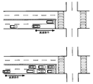
- the vehicle may perform deceleration control near the stop line.
- deceleration control may be performed at a position away from the stop line. Therefore, in the situation shown in FIG. 11, in the technique described in Patent Document 1, even when the same road is driven in the same direction, the timing of turning on the brake to be learned is greatly different every time.
- the driving pattern could not be specified.
- the present invention has been made to solve the above-described conventional problems, and the vehicle decelerates in the deceleration action even on the road where the content of the deceleration action is likely to vary due to disturbance such as a road with heavy traffic.
- a deceleration end point storage system capable of appropriately storing the completed deceleration end point, a driving support system and a driving support method capable of performing appropriate vehicle driving support based on the stored deceleration end point And to provide a computer program.
- the deceleration end point storage system (1) includes a deceleration action detecting means (13) for detecting a deceleration action of the vehicle, and the vehicle has finished decelerating in the detected deceleration action.
- the specified deceleration end point is stored as the same deceleration end point as the other deceleration end point searched, and the predetermined range is the specified deceleration end point Characterized in that different ranges are set according to the road type of a road.
- “store the deceleration end point” means a point indicating the position of the deceleration end point (for example, on the near side or the traveling direction side of the deceleration end point). It may be configured to store the position coordinates of a point moved by a certain distance.
- a driving support system, a driving support method, and a computer program according to the present invention include a driving support system that supports driving of a vehicle that performs deceleration, a driving support method that supports driving of a vehicle using the system, and the system. Is a computer program that realizes the following.
- a deceleration action detecting means (13) for detecting a deceleration action of the vehicle for detecting a deceleration action of the vehicle
- the other deceleration end point within the predetermined range of the deceleration end point is searched from among the above, and if the other deceleration end point exists within the predetermined range as a result of the search, the specified deceleration end The point is stored as the same deceleration end point as the other deceleration end point searched, and the predetermined range is set to a different range depending on the road type of the road where the specified deceleration end point is located, and the target The setting means sets the deceleration end target point based on the history of the deceleration end point stored as the same deceleration end point.
- the “forward in the traveling direction” may be a range in front of the traveling direction of the vehicle along the road along which the vehicle moves, or a range within a predetermined angle with respect to the traveling direction of the vehicle regardless of the route. Also good. Furthermore, when a guide route is set, it may be a range ahead of the traveling direction of the vehicle along the guide route. Further, “supporting driving” includes not only the case where control relating to driving such as acceleration and deceleration of the vehicle is performed, but also the case where display guidance and voice guidance are performed.
- deceleration end point storage system having the above-described configuration, irregular deceleration behavior is excluded even on roads in which the content of deceleration behavior is likely to vary due to disturbances such as roads with heavy traffic.
- it is possible to appropriately store the deceleration end point where the vehicle has ended deceleration in the deceleration action.
- irregular deceleration behavior can be achieved even for roads in which the content of the deceleration behavior tends to vary due to disturbances such as roads with heavy traffic.
- the deceleration end target point is set based on the history of the deceleration end point stored as the same deceleration end point, and the vehicle driving is supported so that the vehicle decelerates at the deceleration end target point.
- the deceleration end target point it is possible to set the deceleration end target point to an appropriate position based on the learning data even on a road where the content of the deceleration action is likely to vary due to disturbance such as a road with many roads.
- the vehicle can be decelerated to an appropriate speed with an appropriate deceleration without sudden acceleration / deceleration.
- the battery in a hybrid vehicle or an EV vehicle, the battery can be charged by the regenerative brake. It becomes possible to carry out with efficiency.
- FIG. 1 is a block diagram showing a navigation device according to the present embodiment.
- FIG. 2 is a diagram illustrating a deceleration end point.
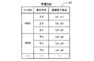
- FIG. 3 is a diagram illustrating an example of learning data stored in the learning DB.
- FIG. 4 is a flowchart of the driving support processing program according to the present embodiment.
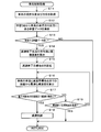
- FIG. 5 is a flowchart of a sub-processing program for vehicle control processing according to the present embodiment.
- FIG. 6 is a diagram illustrating a deceleration end target point.
- FIG. 7 is a diagram showing an ideal deceleration curve.
- FIG. 8 is a flowchart of a sub-processing program for learning processing according to the present embodiment.
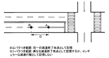
- FIG. 9 is a diagram illustrating a method for setting the variation range.
- FIG. 10 is a diagram illustrating a learning data storage method.
- FIG. 11 is a diagram for explaining problems in conventional driving assistance.
- FIG. 1 is a block diagram showing a navigation device 1 according to this embodiment.
- the navigation device 1 includes a current position detection unit 11 that detects a current position of a vehicle on which the navigation device 1 is mounted, a data recording unit 12 that records various data, A navigation ECU 13 that performs various arithmetic processes based on the input information, an operation unit 14 that receives operations from the user, and a liquid crystal display 15 that displays a map around the vehicle and facility information related to the facility to the user. Communicating between a speaker 16 that outputs voice guidance related to route guidance, a DVD drive 17 that reads a DVD as a storage medium, and an information center such as a probe center or VICS (registered trademark: Vehicle Information and Communication System) center And a communication module 18 for performing.
- the navigation device 1 is connected to a vehicle control ECU 19 that performs various controls on the vehicle on which the navigation device 1 is mounted via an in-vehicle network such as CAN.
- the current position detection unit 11 includes a GPS 21, a vehicle speed sensor 22, a steering sensor 23, a gyro sensor 24, and the like, and can detect the current vehicle position, direction, vehicle traveling speed, current time, and the like.
- the vehicle speed sensor 22 is a sensor for detecting a moving distance and a vehicle speed of the vehicle, generates a pulse according to the rotation of the driving wheel of the vehicle, and outputs a pulse signal to the navigation ECU 13.
- navigation ECU13 calculates the rotational speed and moving distance of a driving wheel by counting the generated pulse.
- the navigation device 1 does not have to include all the four types of sensors, and the navigation device 1 may include only one or more types of sensors.
- the data recording unit 12 reads an external storage device and a hard disk (not shown) as a recording medium, a map information DB 31 and a learning DB 32 recorded on the hard disk, a predetermined program, and the like, and writes predetermined data to the hard disk. And a recording head (not shown) which is a driver for this purpose.
- the data recording unit 12 may be configured by a memory card, an optical disk such as a CD or a DVD, instead of the hard disk.
- the map information DB 31 is, for example, link data 33 regarding roads (links), node data 34 regarding node points, branch point data 35 regarding each branch point, point data regarding points such as facilities, and a map for displaying a map.
- the storage means stores display data, search data for searching for a route, search data for searching for a point, and the like.
- the link data 33 for example, a link ID for identifying the link, end node information for specifying a node located at the end of the link, road type of the road constituting the link, number of lanes, lane The width and the like are stored.
- the node data 34 stores a node ID for identifying the node, position coordinates of the node, connection destination node information for specifying a connection destination node to which the node is connected via a link, and the like.
- the branch point data 35 relevant node information for specifying a node forming the branch point (intersection), connection link information for specifying a link connected to the branch point (hereinafter referred to as a connection link), a branch point The branch point shape information etc. for specifying the shape (for example, the number of links connected to the branch point, the connection angle, etc.) are stored.
- the learning DB 32 is a storage means for storing learning data based on the past traveling history of the vehicle.
- the learning data stored in the learning DB 32 is stored for the deceleration end point where the vehicle has finished decelerating when the vehicle has decelerated. More specifically, the deceleration end point is a point P where the vehicle stops when the vehicle finally stops as shown in FIG. On the other hand, when the vehicle accelerates without finally stopping, the point Q changes from deceleration to acceleration.
- FIG. 3 is a diagram showing an example of learning data stored in the learning DB 32.
- the learning DB 32 stores the deceleration end points for each link and for each traveling direction, and stores the deceleration end points in a cumulative manner.
- the deceleration control points for a plurality of times of traveling are stored. It should be noted that a plurality of deceleration control points stored for the same link and the same direction are rarely the same point, and there is some variation.
- the deceleration end points stored in the same link and the same direction as described later, and the deceleration end points located within the predetermined range are the same even if they are not at the same point. It is stored as learning data for the deceleration end point.
- the deceleration end point located outside the predetermined range is based on a deceleration action based on a different factor or an irregular deceleration action, and is stored in the learning DB 32 as learning data for a different deceleration end point or stored in the learning DB 32 A configuration that does not memorize is also acceptable.
- And navigation ECU13 uses the position coordinate of the deceleration end point memorize
- stored in learning DB32 is good also as memorize
- the point on the near side of the predetermined distance from the deceleration end point is a point that defines the start condition of the driving assistance of the vehicle, and the deceleration control is performed when the deceleration action is performed with the vehicle passing through the point.
- Driving assistance will be provided.
- the navigation ECU (Electronic Control Unit) 13 is an electronic control unit that controls the entire navigation device 1.
- the CPU 41 as an arithmetic device and a control device, and a working memory when the CPU 41 performs various arithmetic processes.
- an internal storage device such as a flash memory 44 for storing the program.
- the navigation ECU 13 constitutes various means as processing algorithms.
- the deceleration action detecting means detects the deceleration action of the vehicle.
- the deceleration end point specifying means specifies a deceleration end point at which the vehicle ends deceleration in the detected deceleration action.
- the deceleration end point storage means stores the specified deceleration end point.
- the target setting means sets, on the road, a deceleration end target point that is a target deceleration end point when a deceleration action is performed on the vehicle, based on the stored history of the deceleration end point.
- the driving support means assists the driving of the vehicle so that the deceleration of the vehicle ends at the deceleration end target point when there is a deceleration end target point ahead of the traveling direction of the vehicle.
- the operation unit 14 is operated when inputting a departure point as a travel start point and a destination point as a travel end point, and includes a plurality of operation switches (not shown) such as various keys and buttons. Then, the navigation ECU 13 performs control to execute various corresponding operations based on switch signals output by pressing the switches.
- the operation unit 14 can also be configured by a touch panel provided on the front surface of the liquid crystal display 15. Moreover, it can also be comprised with a microphone and a speech recognition apparatus.
- the liquid crystal display 15 also includes a map image including a road, traffic information, operation guidance, operation menu, key guidance, a planned travel route from the departure point to the destination, guidance information along the planned travel route, news, weather Forecast, time, mail, TV program, etc. are displayed.
- the speaker 16 outputs voice guidance for guiding traveling along the guidance route and traffic information guidance based on an instruction from the navigation ECU 13.
- the DVD drive 17 is a drive that can read data recorded on a recording medium such as a DVD or a CD. Based on the read data, music and video are reproduced, the map information DB 31 is updated, and the like.
- the communication module 18 is a communication for receiving traffic information composed of information such as traffic jam information, regulation information, and traffic accident information transmitted from a traffic information center such as a VICS (registered trademark) center or a probe center.
- a traffic information center such as a VICS (registered trademark) center or a probe center.
- a mobile phone or DCM is applicable.
- the vehicle control ECU 19 is an electronic control unit that controls the vehicle on which the navigation device 1 is mounted.
- the navigation ECU 13 can acquire the vehicle state (for example, the engine speed, the gear ratio, the accelerator opening, etc.) based on the data acquired from the vehicle control ECU 19 via the CAN. Further, the navigation ECU 13 transmits an instruction signal to the vehicle control ECU 19 via the CAN to perform a downshift and a brake operation, and performs vehicle deceleration control as described later.
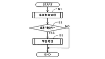
- FIG. 4 is a flowchart of the driving support processing program according to the present embodiment.
- the driving support processing program is a program that is executed after the ACC of the vehicle is turned on and performs driving support related to the deceleration of the vehicle based on the learning result.
- the programs shown in the flowcharts of FIGS. 4, 5 and 8 below are stored in the RAM 42 and the ROM 43 provided in the navigation device 1 and are executed by the CPU 41.
- step (hereinafter abbreviated as S) 1 in the driving support processing program the CPU 41 executes a vehicle control process (FIG. 5) described later.
- the vehicle control process sets a deceleration end point (deceleration end target point) that is a target when deceleration action is performed on the vehicle based on the learning data stored in the learning DB 32, and the set deceleration end target. This is a process of supporting driving of the vehicle so that the deceleration of the vehicle ends at the point.
- the CPU 41 determines whether or not the vehicle has decelerated based on the detection result of the vehicle speed sensor 22 and the vehicle information acquired from the vehicle control ECU 19.
- the deceleration action includes deceleration by engine brake in addition to deceleration by operating the foot brake. Therefore, even if the foot brake is not operated, if the accelerator is turned off and the vehicle is decelerated by the engine brake, it is determined that the vehicle has been decelerated. It does not matter whether the vehicle has finally stopped.
- the CPU 41 executes a learning process (FIG. 8) described later.
- the learning process is a process for updating the learning data stored in the learning DB 32 based on the deceleration action performed in the vehicle.
- FIG. 5 is a flowchart of a sub-processing program for vehicle control processing.
- the CPU 41 acquires the current position and direction of the vehicle based on the detection result of the current position detection unit 11.
- a map matching process for specifying the current position of the vehicle on the map data is also performed.
- the high-accuracy location technology detects a white line and road surface paint information captured from a camera behind the vehicle by image recognition, and further compares the white line and road surface paint information with a map information DB stored in advance, thereby driving. This is a technology that makes it possible to detect lanes and highly accurate vehicle positions. The details of the high-accuracy location technology are already known and will be omitted.
- the CPU 41 falls within a predetermined distance (for example, within 250 m) ahead of the traveling direction of the vehicle in the learning data stored in the learning DB 32 based on the current position and direction of the vehicle acquired in S11. Search for some learning data.
- the learning data stored in the learning DB 32 is a deceleration end point where the vehicle finishes decelerating when the vehicle decelerates as described above (FIG. 3), and a learning process described later (FIG. 8). Stored or updated.
- learning data having a deceleration end point within a predetermined distance ahead of the traveling direction of the vehicle is a search target.
- the CPU 41 determines whether or not there is learning data having a deceleration end point within a predetermined distance ahead in the traveling direction of the vehicle.
- the CPU 41 calculates the average value and the standard deviation of the deceleration end points included in the learning data based on the learning data determined to be ahead of the traveling direction of the vehicle.
- learning data for the same deceleration end point is stored.
- the CPU 41 extracts all learning data stored as the same deceleration end point in the traveling direction of the vehicle from the learning DB 32, and averages the position coordinates of the deceleration end points included in each learning data. And calculate the standard deviation. If the corresponding learning data is only 1, the process of S14 is not performed and the process proceeds to S15.
- the CPU 41 sets a deceleration end target point that is a target deceleration end point when a deceleration action is performed in the vehicle. Specifically, as shown in FIG. 6, the CPU 41 sets a deceleration end target at a point moved by a distance of standard deviation ⁇ forward in the traveling direction from the point X that is the average value of the position coordinates of the deceleration end point calculated in S14. Set to a point. When the corresponding learning data is only 1, the deceleration end target point is set in the position coordinates of the deceleration end point of the learning data.
- the CPU 41 acquires the current vehicle speed of the vehicle based on the detection value of the vehicle speed sensor 22. Further, the distance from the current position of the vehicle acquired in S11 to the deceleration end target point set in S15 is calculated.
- the CPU 41 determines whether or not the vehicle has passed the entry determination point and the vehicle is decelerating based on the calculation result of S16 and the vehicle information acquired from the vehicle speed sensor 22 and the vehicle control ECU 19. Determine whether.
- the approach determination point is a point on the near side of a predetermined distance from the deceleration end target point.
- the predetermined distance is a deceleration start point that can draw an ideal deceleration curve and is the timing to start the slowest deceleration when it is assumed that the vehicle is stopped at the deceleration end target point Z as shown in FIG.
- the distance is longer than the distance L from Y to the deceleration end target point Z, for example, 250 m.
- the deceleration action that is the determination criterion in S17 includes deceleration by engine brake in addition to deceleration by operating the foot brake as in S2. Therefore, even if the foot brake is not operated, it is determined that the vehicle is decelerating when the accelerator is turned off and the vehicle is decelerated by the engine brake.
- the CPU 41 performs braking control of the vehicle so that the deceleration of the vehicle is completed at the deceleration termination target point by an aspect as close as possible to the ideal deceleration curve shown in FIG. Specifically, the CPU 41 transmits an instruction signal to the vehicle control ECU 19 via the CAN, thereby performing a downshift and a brake operation, and performing a braking control of the vehicle. As a result, the vehicle can be decelerated to an appropriate speed with an appropriate deceleration without sudden acceleration / deceleration. In particular, in a hybrid vehicle or an EV vehicle, the battery can be charged by the regenerative brake. It becomes possible to carry out with efficiency.
- the CPU 41 determines whether or not the vehicle has passed the deceleration target point set in S15.
- FIG. 8 is a flowchart of a sub-processing program for learning processing.
- the CPU 41 acquires the content of the deceleration action performed on the vehicle based on the detection result of the vehicle speed sensor 22 and the vehicle information acquired from the vehicle control ECU 19. Specifically, the position coordinates of the deceleration end point where the vehicle has finished decelerating are acquired (FIG. 2).
- the CPU 41 searches the learning DB 32 and determines whether or not learning data corresponding to the current vehicle deceleration action is already stored in the learning DB 32. Specifically, referring to the learning DB 32 (FIG. 3), when there is learning data that stores the deceleration end point in the same direction of the same link, the learning data corresponding to the deceleration action of the vehicle is already present. It determines with having memorize
- the CPU 41 stores the learning data of the deceleration control point specified in S21 in the learning DB 32 as learning data regarding the new deceleration control point.
- the coordinates of the deceleration end point are stored in association with the link on which the deceleration action was performed and the traveling direction.
- the CPU 41 obtains the road type (the narrow street, the general road, the main road, etc.) of the road having the deceleration control point specified in S21 and the road type of the intersection road intersecting with the road. If the deceleration control point is in front of the curve or near the toll gate and not near the intersection, there is no intersection road, so only the road type of the road with the deceleration control point is acquired.
- the CPU 41 sets a variation range based on the road type acquired in S24.
- the variation range defines a range in which the learning data is regarded as learning data related to the same deceleration end point, and the vehicle performs a deceleration action a plurality of times in the same link and in the same direction, and is set as a variation.
- the plurality of deceleration end points are stored as learning data for the same deceleration end point.
- the CPU 41 as shown in FIG. 9, the road type (narrow street, general road, main road, etc.) of the road where the deceleration control point is located and the road type (narrow street, general road) of the intersection road intersecting with the road.
- the range of variation is set according to the combination of the road and the main road. For example, when the road type of the road with the deceleration control point is a narrow street and the road type of the intersection road is a narrow street, the variation range is set to 15 m. On the other hand, when the road type of the road with the deceleration control point is the main road and the road type of the intersection road is the main road, the variation range is set to 50 m.
- the variation range is set to a wider range as the combination of roads is predicted to cause a large amount of traffic and variations in deceleration end points are likely to occur (the combination in the lower part of FIG. 9).
- the variation range is set only by the road type of the road with the deceleration control point. For example, it is 15 m for a narrow street, 30 m for a general road, and 50 m for a main road.
- the CPU 41 searches the learning DB 32, and within the variation range set in S25 from the deceleration end point included in the learning data corresponding to the current vehicle deceleration action already stored in the learning DB 32. Then, it is determined whether there is a deceleration end point of the current deceleration travel. In addition, when there are a plurality of learning data corresponding to the deceleration action of the current vehicle already stored in the learning DB 32, it is within the variation range set in S25 from all the deceleration end points included in each learning data.
- deceleration end point for the current deceleration travel
- deceleration end point for the current deceleration travel is within a variation range set in S25 from at least one deceleration end point. It may be determined whether or not.
- the learning data of the deceleration control point specified in S21 is used as learning data related to the same deceleration control point together with the existing learning data determined to be within the variation range.
- the learning DB 32 stores the coordinates of the deceleration end point in association with the link on which the deceleration action was performed and the traveling direction.
- the learning data based on the current deceleration action is stored as learning data for different deceleration end points. Note that the process may be terminated without being stored in the learning DB 32.
- the deceleration end point B is estimated to be based on a deceleration action based on different factors or an irregular deceleration action,
- the deceleration end point B is stored as learning data for different deceleration end points, or is not stored as learning data.
- the deceleration end target point is set using only the deceleration end point A in the vehicle control process (FIG. 5) described above. .
- the deceleration end point at which the vehicle has finished decelerating in the deceleration action is specified (S21)
- a variation range according to the road type at which the deceleration end point is located is set (S25)
- the learning data stored in the learning DB 32 is When learning data of other deceleration end points within the variation range set from the current deceleration end point already exist, they are stored as learning data of the same deceleration end point (S27).
- a deceleration end target point is set based on the history of the deceleration end point stored as the same deceleration end point, and driving of the vehicle is supported so that the deceleration of the vehicle ends at the deceleration end target point (S18).
- S18 deceleration end target point
- the vehicle can be decelerated to an appropriate speed with an appropriate deceleration without sudden acceleration / deceleration.
- the battery can be charged by the regenerative brake. It becomes possible to carry out with efficiency.
- the braking control is performed so that the vehicle deceleration ends at the deceleration end target point.
- the deceleration end point is the point where the vehicle stopped or changed from deceleration to acceleration, it is possible to set an appropriate deceleration end target point regardless of whether or not the vehicle finally stopped It becomes.
- the range considered as the same deceleration end point is set. It is possible to determine whether the road is likely to vary, and based on the determination result, it is possible to appropriately set a range that is regarded as the same deceleration end point.
- the deceleration end target point since the point where the distance of the standard deviation is moved forward in the traveling direction from the average value of the history of the deceleration end points stored as the same deceleration end point is set as the deceleration end target point, the content of the deceleration action varies. Even if it has occurred, it is possible to set an appropriate deceleration end target point.
- a deceleration end point for example, a stop position of the vehicle
- the range considered as the same deceleration end point is set wider, so the road type is more likely to vary in the content of deceleration action from the road type,
- the range regarded as the same deceleration end point can be set to a wider range. Therefore, it is possible to set a deceleration end target point in consideration of variations in the content of the deceleration action.
- the present invention is not limited to the above-described embodiment, and various improvements and modifications can be made without departing from the scope of the present invention.
- the braking control for the vehicle is performed as the driving assistance for the vehicle, but the display guidance or voice guidance may be used. Specifically, guidance for instructing the timing and amount of deceleration is performed so that the vehicle decelerates by drawing an ideal deceleration curve up to the deceleration end target point.
- the variation range is set based on a combination of a road type (a narrow street, a general road, a main road, etc.) of a road having a deceleration control point and a road type of an intersecting road that intersects the road. However, it may be set based only on the road type of the road having the deceleration control point. In addition to the road type, the variation range may be set based on information that can predict the traffic volume (for example, the average vehicle speed and the number of lanes of the road).
- a road type a narrow street, a general road, a main road, etc.
- the variation range may be set based on information that can predict the traffic volume (for example, the average vehicle speed and the number of lanes of the road).
- the driving support processing program (FIGS. 4, 5, and 8) of the present embodiment is executed by the navigation ECU 13 included in the navigation device, but may be executed by the vehicle control ECU 19. Further, the processing may be shared by a plurality of ECUs.
- the present invention can be applied to various devices capable of controlling the vehicle via the vehicle control ECU 19.
- the present invention can also be applied to in-vehicle devices other than navigation devices, mobile terminals such as mobile phones, smartphones and PDAs, personal computers, and the like (hereinafter referred to as mobile terminals).
- the present invention can be applied to a system including a server and a mobile terminal.
- each step of the above-described vehicle control processing program (FIGS. 4, 5, and 8) may be configured to be implemented by either a server or a portable terminal.
- the present invention when the present invention is applied to a mobile terminal or the like, it is possible to provide driving support for a vehicle other than an automobile, for example, a two-wheeled vehicle or the like that is driven by a user such as a mobile terminal.
- the driving support system can also have the following configuration, and in that case, the following effects can be obtained.
- the first configuration is as follows.
- the driving support means performs braking control so that the deceleration of the vehicle ends at the deceleration end target point when there is a deceleration end target point ahead of the traveling direction of the vehicle and the vehicle performs a deceleration action. It is characterized by that.
- the driving support system having the above-described configuration, when there is a deceleration end target point ahead of the traveling direction of the vehicle and deceleration action is performed on the vehicle, the deceleration of the vehicle ends at the deceleration end target point. Since the braking control is performed as described above, it is possible to appropriately support the action when the vehicle performs the deceleration action. That is, in a situation where the vehicle does not need to perform a deceleration action, there is no possibility that unnecessary assistance is performed.
- the second configuration is as follows.
- the deceleration end point is a point where the vehicle stops or a point where the vehicle changes from deceleration to acceleration.
- the deceleration end point is a point where the vehicle has stopped or a point where the vehicle has changed from deceleration to acceleration, so that appropriate deceleration can be performed regardless of whether or not the vehicle has finally stopped. It is possible to set an end target point.
- the third configuration is as follows.
- the deceleration end point is specified in the vicinity of the intersection, and the predetermined range is set based on a combination of the road type of the road where the specified deceleration end point is located and the road type of the intersection road that intersects the road.
- the range considered as the same deceleration end point is set based on the combination of the road type of the road where the deceleration end point is located and the road type of the intersection road intersecting the road. Therefore, it is possible to determine whether or not the road type tends to vary in the content of the deceleration action from the road type, and based on the determination result, it is possible to appropriately set the range regarded as the same deceleration end point .
- the fourth configuration is as follows.
- the target setting means calculates the average value and the standard deviation of the history of the deceleration end point stored as the same deceleration end point, and forwards in the traveling direction from the average value of the history of the deceleration end point stored as the same deceleration end point.
- the point where the distance corresponding to the standard deviation is moved is set as the deceleration end target point.
- the point where the distance of the standard deviation is moved forward in the traveling direction from the average value of the history of the deceleration end points stored as the same deceleration end point is set as the deceleration end target point.
- a deceleration end point (for example, a stop position of the vehicle) comes before the deceleration target point. It is possible to prevent the vehicle from being reaccelerated.
- the fifth configuration is as follows.
- the predetermined range is characterized in that the predetermined range is set to a wider range as the road where the specified deceleration end point is a road type with a large amount of traffic.
- the range to be regarded as the same deceleration end point is set wider. It is possible to set a range that is regarded as the same deceleration end point to a wider range as the road is more likely to vary. Accordingly, it is possible to set a deceleration end target point in consideration of variations in the content of the deceleration action.
Landscapes
- Engineering & Computer Science (AREA)
- Physics & Mathematics (AREA)
- General Physics & Mathematics (AREA)
- Mechanical Engineering (AREA)
- Transportation (AREA)
- Automation & Control Theory (AREA)
- Theoretical Computer Science (AREA)
- Software Systems (AREA)
- Remote Sensing (AREA)
- Radar, Positioning & Navigation (AREA)
- Life Sciences & Earth Sciences (AREA)
- Atmospheric Sciences (AREA)
- Mathematical Physics (AREA)
- Computer Vision & Pattern Recognition (AREA)
- General Engineering & Computer Science (AREA)
- Computing Systems (AREA)
- Artificial Intelligence (AREA)
- Evolutionary Computation (AREA)
- Data Mining & Analysis (AREA)
- Medical Informatics (AREA)
- Aviation & Aerospace Engineering (AREA)
- Navigation (AREA)
- Traffic Control Systems (AREA)
Abstract
Description
尚、「減速終了地点を記憶する」とは、減速終了地点自体の位置座標を記憶することに加えて、減速終了地点の位置を示唆する地点(例えば減速終了地点の手前側や進行方向側に一定距離移動させた地点)の位置座標を記憶する構成としても良い。
尚、「進行方向前方」とは、車両が移動する道なりの道路に沿った車両の進行方向前方の範囲としても良いし、経路と関係なく車両の進行方位に対して所定角度以内の範囲としても良い。更に、案内経路が設定されている場合には案内経路に沿った車両の進行方向前方の範囲としても良い。
また、「運転を支援する」とは、車両に対する加速や減速等の駆動に関する制御を行う場合に加えて、表示案内や音声案内を行う場合も含む。
現在位置検出部11は、GPS21、車速センサ22、ステアリングセンサ23、ジャイロセンサ24等からなり、現在の車両の位置、方位、車両の走行速度、現在時刻等を検出することが可能となっている。ここで、特に車速センサ22は、車両の移動距離や車速を検出する為のセンサであり、車両の駆動輪の回転に応じてパルスを発生させ、パルス信号をナビゲーションECU13に出力する。そして、ナビゲーションECU13は発生するパルスを計数することにより駆動輪の回転速度や移動距離を算出する。尚、上記4種類のセンサをナビゲーション装置1が全て備える必要はなく、これらの内の1又は複数種類のセンサのみをナビゲーション装置1が備える構成としても良い。
尚、地図情報DB31や学習DB32を外部のサーバに記憶し、ナビゲーション装置1が通信によりデータの更新や取得を行う構成としても良い。
一方、減速終了地点Aから減速終了地点Bまでの距離Dがバラつき距離より大きい場合には、減速終了地点Bは異なる要因に基づく減速行動又はイレギュラーな減速行動に基づくものであると推定し、減速終了地点Bは異なる減速終了地点に対する学習データとして記憶するか、或いは学習データとして記憶しない。その結果、次回以降に車両が同一リンクを同一方向に走行した場合には、前述した車両制御処理(図5)において、減速終了地点Aのみを用いて減速終了目標地点が設定されることとなる。
また、車両の進行方向前方に減速終了目標地点がある場合であって、車両において減速行動が行われた場合に、減速終了目標地点で車両の減速が終了するように制動制御するので、車両が減速行動を行う場合において該行動を適切に支援することが可能となる。即ち、車両が減速行動を行う必要のない状況では、不要な支援が行われる虞がない。
また、減速終了地点は、車両が停止した地点、又は減速から加速に変化した地点とするので、車両が最終的に停止したか否かに関わらず適切な減速終了目標地点を設定することが可能となる。
また、減速終了地点がある道路の道路種別と該道路に交差する交差道路の道路種別との組み合わせに基づいて、同一の減速終了地点とみなす範囲を設定するので、道路種別から減速行動の内容にばらつきが生じ易い道路であるか否かを判定することができ、その判定結果に基づいて同一の減速終了地点とみなす範囲を適切に設定することが可能となる。
また、同一の減速終了地点として記憶された減速終了地点の履歴の平均値から進行方向前方に標準偏差分の距離を移動した地点を減速終了目標地点に設定するので、減速行動の内容にばらつきが生じていた場合であっても適切な減速終了目標地点を設定することが可能となる。また、平均値よりも進行方向前方側に設定するので、車両の運転支援を行う場合に、減速目標地点よりも進行方向前方側に減速の終了地点(例えば車両の停止位置)がくること、即ち車両の再加速が行われることを防止することが可能となる。
また、減速終了地点がある道路が交通量の多い道路種別である程、同一の減速終了地点とみなす範囲を広く設定するので、道路種別から減速行動の内容にばらつきが生じ易い道路である程、同一の減速終了地点とみなす範囲をより広い範囲に設定することが可能となる。従って、減速行動の内容のばらつきを考慮して、減速終了目標地点を設定することが可能となる。
例えば、本実施形態では、車両に対する運転支援として車両に対する制動制御を行っているが、表示案内や音声案内を行う構成としても良い。具体的には、減速終了目標地点までに理想の減速曲線を描いて車両が減速するように、減速のタイミングや量を指示する案内を行う。
運転支援手段は、車両の進行方向前方に減速終了目標地点がある場合であって、車両において減速行動が行われた場合に、減速終了目標地点で前記車両の減速が終了するように制動制御することを特徴とする。
上記構成を有する運転支援システムによれば、車両の進行方向前方に減速終了目標地点がある場合であって、車両において減速行動が行われた場合に、減速終了目標地点で車両の減速が終了するように制動制御するので、車両が減速行動を行う場合において該行動を適切に支援することが可能となる。即ち、車両が減速行動を行う必要のない状況では、不要な支援が行われる虞がない。
減速終了地点は、車両が停止した地点、又は減速から加速に変化した地点であることを特徴とする。
上記構成を有する運転支援システムによれば、減速終了地点は、車両が停止した地点、又は減速から加速に変化した地点とするので、車両が最終的に停止したか否かに関わらず適切な減速終了目標地点を設定することが可能となる。
減速終了地点は、交差点付近に特定され、所定範囲は、特定された減速終了地点がある道路の道路種別と該道路に交差する交差道路の道路種別との組み合わせに基づいて設定されることを特徴とする。
上記構成を有する運転支援システムによれば、減速終了地点がある道路の道路種別と該道路に交差する交差道路の道路種別との組み合わせに基づいて、同一の減速終了地点とみなす範囲を設定するので、道路種別から減速行動の内容にばらつきが生じ易い道路であるか否かを判定することができ、その判定結果に基づいて同一の減速終了地点とみなす範囲を適切に設定することが可能となる。
目標設定手段は、同一の減速終了地点として記憶された減速終了地点の履歴の平均値と標準偏差を算出し、同一の減速終了地点として記憶された減速終了地点の履歴の平均値から進行方向前方に標準偏差分の距離を移動した地点を減速終了目標地点に設定することを特徴とする。
上記構成を有する運転支援システムによれば、同一の減速終了地点として記憶された減速終了地点の履歴の平均値から進行方向前方に標準偏差分の距離を移動した地点を減速終了目標地点に設定するので、減速行動の内容にばらつきが生じていた場合であっても適切な減速終了目標地点を設定することが可能となる。また、平均値よりも進行方向前方側に設定するので、車両の運転支援を行う場合に、減速目標地点よりも進行方向前方側に減速の終了地点(例えば車両の停止位置)がくること、即ち車両の再加速が行われることを防止することが可能となる。
所定範囲は、特定された減速終了地点がある道路が交通量の多い道路種別である程、所定範囲を広い範囲に設定することを特徴とする。
上記構成を有する運転支援システムによれば、減速終了地点がある道路が交通量の多い道路種別である程、同一の減速終了地点とみなす範囲を広く設定するので、道路種別から減速行動の内容にばらつきが生じ易い道路である程、同一の減速終了地点とみなす範囲をより広い範囲に設定することが可能となる。従って、減速行動の内容のばらつきを考慮して、減速終了目標地点を設定することが可能となる。
13 ナビゲーションECU
19 車両制御ECU
41 CPU
42 RAM
43 ROM
Claims (9)
- 車両の減速行動を検出する減速行動検出手段と、
検出された前記減速行動において前記車両が減速を終了した減速終了地点を特定する減速終了地点特定手段と、
特定された前記減速終了地点を記憶する減速終了地点記憶手段と、を有し、
前記減速終了地点記憶手段は、
前記減速終了地点が特定された場合に、既に記憶された前記減速終了地点の内から、該減速終了地点の所定範囲内にある他の減速終了地点を検索し、
検索の結果、前記所定範囲内に前記他の減速終了地点が存在する場合に、特定された前記減速終了地点を検索された前記他の減速終了地点と同一の減速終了地点として記憶し、
前記所定範囲は、特定された前記減速終了地点がある道路の道路種別に応じて異なる範囲が設定されることを特徴とする減速終了地点記憶システム。 - 車両の減速行動を検出する減速行動検出手段と、
検出された前記減速行動において前記車両が減速を終了した減速終了地点を特定する減速終了地点特定手段と、
特定された前記減速終了地点を記憶する減速終了地点記憶手段と、
記憶された前記減速終了地点の履歴に基づいて、前記車両において減速行動が行われる際に目標とする減速終了地点である減速終了目標地点を道路に対して設定する目標設定手段と、
前記車両の進行方向前方に前記減速終了目標地点がある場合に、前記減速終了目標地点で前記車両の減速が終了するように車両の運転を支援する運転支援手段と、を有し、
前記減速終了地点記憶手段は、
前記減速終了地点が特定された場合に、既に記憶された前記減速終了地点の内から、該減速終了地点の所定範囲内にある他の減速終了地点を検索し、
検索の結果、前記所定範囲内に前記他の減速終了地点が存在する場合に、特定された前記減速終了地点を検索された前記他の減速終了地点と同一の減速終了地点として記憶し、
前記所定範囲は、特定された前記減速終了地点がある道路の道路種別に応じて異なる範囲が設定され、
前記目標設定手段は、同一の減速終了地点として記憶された前記減速終了地点の履歴に基づいて、前記減速終了目標地点を設定することを特徴とする運転支援システム。 - 前記運転支援手段は、前記車両の進行方向前方に前記減速終了目標地点がある場合であって、前記車両において減速行動が行われた場合に、前記減速終了目標地点で前記車両の減速が終了するように制動制御することを特徴とする請求項2に記載の運転支援システム。
- 前記減速終了地点は、前記車両が停止した地点、又は減速から加速に変化した地点であることを特徴とする請求項2又は請求項3に記載の運転支援システム。
- 前記減速終了地点は、交差点付近に特定され、
前記所定範囲は、特定された前記減速終了地点がある前記道路の道路種別と該道路に交差する交差道路の道路種別との組み合わせに基づいて設定されることを特徴とする請求項2乃至請求項4のいずれかに記載の運転支援システム。 - 前記目標設定手段は、
同一の減速終了地点として記憶された前記減速終了地点の履歴の平均値と標準偏差を算出し、
同一の減速終了地点として記憶された前記減速終了地点の履歴の平均値から進行方向前方に前記標準偏差分の距離を移動した地点を前記減速終了目標地点に設定することを特徴とする請求項2乃至請求項5のいずれかに記載の運転支援システム。 - 前記所定範囲は、特定された前記減速終了地点がある前記道路が交通量の多い道路種別である程、前記所定範囲を広い範囲に設定することを特徴とする請求項2乃至請求項6のいずれかに記載の運転支援システム。
- 車両の減速行動を検出する減速行動検出ステップと、
検出された前記減速行動において前記車両が減速を終了した減速終了地点を特定する減速終了地点特定ステップと、
特定された前記減速終了地点を記憶する減速終了地点記憶ステップと、
記憶された前記減速終了地点の履歴に基づいて、前記車両において減速行動が行われる際に目標とする減速終了地点である減速終了目標地点を道路に対して設定する目標設定ステップと、
前記車両の進行方向前方に前記減速終了目標地点がある場合に、前記減速終了目標地点で前記車両の減速が終了するように車両の運転を支援する運転支援ステップと、を有し、
前記減速終了地点記憶ステップは、
前記減速終了地点が特定された場合に、既に記憶された前記減速終了地点の内から、該減速終了地点の所定範囲内にある他の減速終了地点を検索し、
検索の結果、前記所定範囲内に前記他の減速終了地点が存在する場合に、特定された前記減速終了地点を検索された前記他の減速終了地点と同一の減速終了地点として記憶し、
前記所定範囲は、特定された前記減速終了地点がある道路の道路種別に応じて異なる範囲が設定され、
前記目標設定ステップは、同一の減速終了地点として記憶された前記減速終了地点の履歴に基づいて、前記減速終了目標地点を設定することを特徴とする運転支援方法。 - コンピュータに、
車両の減速行動を検出する減速行動検出機能と、
検出された前記減速行動において前記車両が減速を終了した減速終了地点を特定する減速終了地点特定機能と、
特定された前記減速終了地点を記憶する減速終了地点記憶機能と、
記憶された前記減速終了地点の履歴に基づいて、前記車両において減速行動が行われる際に目標とする減速終了地点である減速終了目標地点を道路に対して設定する目標設定機能と、
前記車両の進行方向前方に前記減速終了目標地点がある場合に、前記減速終了目標地点で前記車両の減速が終了するように車両の運転を支援する運転支援機能と、を実行させるコンピュータプログラムであって、
前記減速終了地点記憶機能は、
前記減速終了地点が特定された場合に、既に記憶された前記減速終了地点の内から、該減速終了地点の所定範囲内にある他の減速終了地点を検索し、
検索の結果、前記所定範囲内に前記他の減速終了地点が存在する場合に、特定された前記減速終了地点を検索された前記他の減速終了地点と同一の減速終了地点として記憶し、
前記所定範囲は、特定された前記減速終了地点がある道路の道路種別に応じて異なる範囲が設定され、
前記目標設定機能は、同一の減速終了地点として記憶された前記減速終了地点の履歴に基づいて、前記減速終了目標地点を設定することを特徴とするコンピュータプログラム。
Priority Applications (3)
| Application Number | Priority Date | Filing Date | Title |
|---|---|---|---|
| DE112014000857.5T DE112014000857B4 (de) | 2013-03-29 | 2014-03-03 | Verlangsamungsendortspeichersystem, Fahrassistenzsystem, Fahrassistenzverfahren und Computerprogramm |
| CN201480010472.3A CN105009180B (zh) | 2013-03-29 | 2014-03-03 | 减速结束地点存储系统、驾驶辅助系统及驾驶辅助方法 |
| US14/774,475 US9889828B2 (en) | 2013-03-29 | 2014-03-03 | Deceleration end location storage system, drive assist system, drive assist method, and computer program |
Applications Claiming Priority (2)
| Application Number | Priority Date | Filing Date | Title |
|---|---|---|---|
| JP2013-074880 | 2013-03-29 | ||
| JP2013074880A JP5655107B2 (ja) | 2013-03-29 | 2013-03-29 | 減速終了地点記憶システム、運転支援システム、運転支援方法及びコンピュータプログラム |
Publications (1)
| Publication Number | Publication Date |
|---|---|
| WO2014156482A1 true WO2014156482A1 (ja) | 2014-10-02 |
Family
ID=51623473
Family Applications (1)
| Application Number | Title | Priority Date | Filing Date |
|---|---|---|---|
| PCT/JP2014/055241 Ceased WO2014156482A1 (ja) | 2013-03-29 | 2014-03-03 | 減速終了地点記憶システム、運転支援システム、運転支援方法及びコンピュータプログラム |
Country Status (5)
| Country | Link |
|---|---|
| US (1) | US9889828B2 (ja) |
| JP (1) | JP5655107B2 (ja) |
| CN (1) | CN105009180B (ja) |
| DE (1) | DE112014000857B4 (ja) |
| WO (1) | WO2014156482A1 (ja) |
Families Citing this family (8)
| Publication number | Priority date | Publication date | Assignee | Title |
|---|---|---|---|---|
| JP6448347B2 (ja) * | 2014-12-16 | 2019-01-09 | アイシン・エィ・ダブリュ株式会社 | 減速制御システム、方法およびプログラム |
| US9761065B2 (en) * | 2015-03-09 | 2017-09-12 | Ford Global Technologies, Llc | Regenerative braking coaching system |
| WO2017077807A1 (ja) * | 2015-11-06 | 2017-05-11 | 本田技研工業株式会社 | 車両走行制御装置 |
| KR101798519B1 (ko) * | 2015-12-15 | 2017-11-16 | 현대자동차주식회사 | 긴급 제동 시스템 및 그 제어방법 |
| JP6558239B2 (ja) * | 2015-12-22 | 2019-08-14 | アイシン・エィ・ダブリュ株式会社 | 自動運転支援システム、自動運転支援方法及びコンピュータプログラム |
| DE102017223480A1 (de) * | 2017-12-20 | 2019-06-27 | Robert Bosch Gmbh | Verfahren und Vorrichtung zur automatischen Regelung der Längsdynamik eines Fahrzeugs |
| US20230152100A1 (en) * | 2020-11-19 | 2023-05-18 | Enrique SERNIK | Navigation Methods Using Virtual Celestial Objects |
| JP7447778B2 (ja) * | 2020-12-18 | 2024-03-12 | トヨタ自動車株式会社 | 自動運転制御システム |
Citations (4)
| Publication number | Priority date | Publication date | Assignee | Title |
|---|---|---|---|---|
| JP2009053732A (ja) * | 2007-08-23 | 2009-03-12 | Nissan Motor Co Ltd | 停止目標位置検出装置及び停止目標位置検出方法 |
| JP2011098690A (ja) * | 2009-11-09 | 2011-05-19 | Toyota Motor Corp | 車両用運転支援装置 |
| WO2012039026A1 (ja) * | 2010-09-22 | 2012-03-29 | トヨタ自動車株式会社 | 車両用情報処理装置及びデータベース |
| JP2012117938A (ja) * | 2010-12-01 | 2012-06-21 | Toyota Motor Corp | 車両用情報処理装置 |
Family Cites Families (7)
| Publication number | Priority date | Publication date | Assignee | Title |
|---|---|---|---|---|
| US20040159519A1 (en) * | 2003-02-14 | 2004-08-19 | Gorman Michael J. | Clutch reaction plates with cooling flow path |
| JP5546106B2 (ja) * | 2008-01-23 | 2014-07-09 | 株式会社アドヴィックス | 車両の運動制御装置 |
| JP4992813B2 (ja) * | 2008-04-22 | 2012-08-08 | アイシン・エィ・ダブリュ株式会社 | 運転支援装置、運転支援方法および運転支援プログラム |
| JP2010003013A (ja) * | 2008-06-18 | 2010-01-07 | Aisin Aw Co Ltd | 運転支援装置、運転支援方法および運転支援プログラム |
| JP5644168B2 (ja) * | 2010-04-22 | 2014-12-24 | トヨタ自動車株式会社 | 運転支援装置 |
| CN103221780B (zh) | 2010-10-15 | 2016-08-03 | 丰田自动车株式会社 | 车辆用信息处理系统及驾驶支援系统 |
| CN103229220B (zh) * | 2010-12-01 | 2015-01-14 | 丰田自动车株式会社 | 车辆用信息处理装置 |
-
2013
- 2013-03-29 JP JP2013074880A patent/JP5655107B2/ja active Active
-
2014
- 2014-03-03 US US14/774,475 patent/US9889828B2/en active Active
- 2014-03-03 WO PCT/JP2014/055241 patent/WO2014156482A1/ja not_active Ceased
- 2014-03-03 DE DE112014000857.5T patent/DE112014000857B4/de active Active
- 2014-03-03 CN CN201480010472.3A patent/CN105009180B/zh active Active
Patent Citations (4)
| Publication number | Priority date | Publication date | Assignee | Title |
|---|---|---|---|---|
| JP2009053732A (ja) * | 2007-08-23 | 2009-03-12 | Nissan Motor Co Ltd | 停止目標位置検出装置及び停止目標位置検出方法 |
| JP2011098690A (ja) * | 2009-11-09 | 2011-05-19 | Toyota Motor Corp | 車両用運転支援装置 |
| WO2012039026A1 (ja) * | 2010-09-22 | 2012-03-29 | トヨタ自動車株式会社 | 車両用情報処理装置及びデータベース |
| JP2012117938A (ja) * | 2010-12-01 | 2012-06-21 | Toyota Motor Corp | 車両用情報処理装置 |
Also Published As
| Publication number | Publication date |
|---|---|
| CN105009180B (zh) | 2017-03-08 |
| CN105009180A (zh) | 2015-10-28 |
| JP2014199587A (ja) | 2014-10-23 |
| US20160039395A1 (en) | 2016-02-11 |
| JP5655107B2 (ja) | 2015-01-14 |
| DE112014000857T5 (de) | 2015-10-29 |
| US9889828B2 (en) | 2018-02-13 |
| DE112014000857B4 (de) | 2020-08-06 |
Similar Documents
| Publication | Publication Date | Title |
|---|---|---|
| JP5655107B2 (ja) | 減速終了地点記憶システム、運転支援システム、運転支援方法及びコンピュータプログラム | |
| US10071745B2 (en) | Automated drive assisting system, automated drive assisting method, and computer program | |
| US10315664B2 (en) | Automatic driving assistance system, automatic driving assistance method, and computer program | |
| JP6474307B2 (ja) | 自動運転支援システム、自動運転支援方法及びコンピュータプログラム | |
| US8543293B2 (en) | Route guidance apparatus, route guidance method, and computer program | |
| EP2691741B1 (en) | Driving support system, driving support method and computer program | |
| JP5303591B2 (ja) | 運転支援装置、運転支援方法及びコンピュータプログラム | |
| JP5857535B2 (ja) | 移動案内システム、移動案内装置、移動案内方法及びコンピュータプログラム | |
| US9151636B2 (en) | Travel guidance system, travel guidance apparatus, travel guidance method and computer program | |
| JP5768750B2 (ja) | 車両制御装置、車両制御方法及びコンピュータプログラム | |
| JP2014010561A (ja) | プローブ情報収集システム | |
| JP6174888B2 (ja) | 運転支援システム、運転支援方法及びコンピュータプログラム | |
| JP2014189083A (ja) | 車両制御システム、車両制御方法及びコンピュータプログラム | |
| JP2018063658A (ja) | 走行計画生成装置及びコンピュータプログラム | |
| JP5691915B2 (ja) | 移動案内システム、移動案内装置、移動案内方法及びコンピュータプログラム | |
| JP5831016B2 (ja) | 移動案内システム、移動案内装置、移動案内方法及びコンピュータプログラム | |
| JP5716564B2 (ja) | 移動案内システム、移動案内装置、移動案内方法及びコンピュータプログラム | |
| JP5786522B2 (ja) | 移動案内システム、移動案内装置、移動案内方法及びコンピュータプログラム | |
| JP2012053846A (ja) | 運転支援装置、運転支援方法及びコンピュータプログラム | |
| JP2013029381A (ja) | 移動案内システム、移動案内装置、移動案内方法及びコンピュータプログラム | |
| JP2013024837A (ja) | 移動体位置検出システム、移動体位置検出装置、移動体位置検出方法及びコンピュータプログラム | |
| JP2013024838A (ja) | 信号機情報更新システム、信号機情報更新装置、信号機情報更新方法及びコンピュータプログラム |
Legal Events
| Date | Code | Title | Description |
|---|---|---|---|
| 121 | Ep: the epo has been informed by wipo that ep was designated in this application |
Ref document number: 14775812 Country of ref document: EP Kind code of ref document: A1 |
|
| WWE | Wipo information: entry into national phase |
Ref document number: 1120140008575 Country of ref document: DE Ref document number: 112014000857 Country of ref document: DE |
|
| WWE | Wipo information: entry into national phase |
Ref document number: 14774475 Country of ref document: US |
|
| 122 | Ep: pct application non-entry in european phase |
Ref document number: 14775812 Country of ref document: EP Kind code of ref document: A1 |