WO2014156453A1 - 管 - Google Patents
管 Download PDFInfo
- Publication number
- WO2014156453A1 WO2014156453A1 PCT/JP2014/054823 JP2014054823W WO2014156453A1 WO 2014156453 A1 WO2014156453 A1 WO 2014156453A1 JP 2014054823 W JP2014054823 W JP 2014054823W WO 2014156453 A1 WO2014156453 A1 WO 2014156453A1
- Authority
- WO
- WIPO (PCT)
- Prior art keywords
- reinforced resin
- fiber reinforced
- tube
- pipe
- resin layer
- Prior art date
- Legal status (The legal status is an assumption and is not a legal conclusion. Google has not performed a legal analysis and makes no representation as to the accuracy of the status listed.)
- Ceased
Links
Images









Classifications
-
- B—PERFORMING OPERATIONS; TRANSPORTING
- B32—LAYERED PRODUCTS
- B32B—LAYERED PRODUCTS, i.e. PRODUCTS BUILT-UP OF STRATA OF FLAT OR NON-FLAT, e.g. CELLULAR OR HONEYCOMB, FORM
- B32B1/00—Layered products having a non-planar shape
- B32B1/08—Tubular products
-
- B—PERFORMING OPERATIONS; TRANSPORTING
- B32—LAYERED PRODUCTS
- B32B—LAYERED PRODUCTS, i.e. PRODUCTS BUILT-UP OF STRATA OF FLAT OR NON-FLAT, e.g. CELLULAR OR HONEYCOMB, FORM
- B32B27/00—Layered products comprising a layer of synthetic resin
- B32B27/06—Layered products comprising a layer of synthetic resin as the main or only constituent of a layer, which is next to another layer of the same or of a different material
- B32B27/08—Layered products comprising a layer of synthetic resin as the main or only constituent of a layer, which is next to another layer of the same or of a different material of synthetic resin
-
- B—PERFORMING OPERATIONS; TRANSPORTING
- B32—LAYERED PRODUCTS
- B32B—LAYERED PRODUCTS, i.e. PRODUCTS BUILT-UP OF STRATA OF FLAT OR NON-FLAT, e.g. CELLULAR OR HONEYCOMB, FORM
- B32B27/00—Layered products comprising a layer of synthetic resin
- B32B27/18—Layered products comprising a layer of synthetic resin characterised by the use of special additives
- B32B27/20—Layered products comprising a layer of synthetic resin characterised by the use of special additives using fillers, pigments, thixotroping agents
-
- F—MECHANICAL ENGINEERING; LIGHTING; HEATING; WEAPONS; BLASTING
- F16—ENGINEERING ELEMENTS AND UNITS; GENERAL MEASURES FOR PRODUCING AND MAINTAINING EFFECTIVE FUNCTIONING OF MACHINES OR INSTALLATIONS; THERMAL INSULATION IN GENERAL
- F16L—PIPES; JOINTS OR FITTINGS FOR PIPES; SUPPORTS FOR PIPES, CABLES OR PROTECTIVE TUBING; MEANS FOR THERMAL INSULATION IN GENERAL
- F16L23/00—Flanged joints
- F16L23/02—Flanged joints the flanges being connected by members tensioned axially
- F16L23/024—Flanged joints the flanges being connected by members tensioned axially characterised by how the flanges are joined to, or form an extension of, the pipes
-
- F—MECHANICAL ENGINEERING; LIGHTING; HEATING; WEAPONS; BLASTING
- F16—ENGINEERING ELEMENTS AND UNITS; GENERAL MEASURES FOR PRODUCING AND MAINTAINING EFFECTIVE FUNCTIONING OF MACHINES OR INSTALLATIONS; THERMAL INSULATION IN GENERAL
- F16L—PIPES; JOINTS OR FITTINGS FOR PIPES; SUPPORTS FOR PIPES, CABLES OR PROTECTIVE TUBING; MEANS FOR THERMAL INSULATION IN GENERAL
- F16L9/00—Rigid pipes
- F16L9/12—Rigid pipes of plastics with or without reinforcement
-
- B—PERFORMING OPERATIONS; TRANSPORTING
- B32—LAYERED PRODUCTS
- B32B—LAYERED PRODUCTS, i.e. PRODUCTS BUILT-UP OF STRATA OF FLAT OR NON-FLAT, e.g. CELLULAR OR HONEYCOMB, FORM
- B32B2307/00—Properties of the layers or laminate
- B32B2307/50—Properties of the layers or laminate having particular mechanical properties
- B32B2307/554—Wear resistance
-
- B—PERFORMING OPERATIONS; TRANSPORTING
- B32—LAYERED PRODUCTS
- B32B—LAYERED PRODUCTS, i.e. PRODUCTS BUILT-UP OF STRATA OF FLAT OR NON-FLAT, e.g. CELLULAR OR HONEYCOMB, FORM
- B32B2307/00—Properties of the layers or laminate
- B32B2307/50—Properties of the layers or laminate having particular mechanical properties
- B32B2307/584—Scratch resistance
-
- B—PERFORMING OPERATIONS; TRANSPORTING
- B32—LAYERED PRODUCTS
- B32B—LAYERED PRODUCTS, i.e. PRODUCTS BUILT-UP OF STRATA OF FLAT OR NON-FLAT, e.g. CELLULAR OR HONEYCOMB, FORM
- B32B2307/00—Properties of the layers or laminate
- B32B2307/70—Other properties
- B32B2307/714—Inert, i.e. inert to chemical degradation, corrosion
-
- B—PERFORMING OPERATIONS; TRANSPORTING
- B32—LAYERED PRODUCTS
- B32B—LAYERED PRODUCTS, i.e. PRODUCTS BUILT-UP OF STRATA OF FLAT OR NON-FLAT, e.g. CELLULAR OR HONEYCOMB, FORM
- B32B2597/00—Tubular articles, e.g. hoses, pipes
Definitions
- the present invention relates to a tube having a soft layer and a fiber reinforced resin layer.
- the sand discharging pipe disposed over a long distance is pulled up from the water by a crane or the like while the sand discharging pipe and the flexible sleeve are joined.
- the weight of the steel pipe is large, a large heavy machine is required, the work process is complicated, and the number of workers and the work time are required.
- Patent Document 2 the present applicant, as disclosed in Patent Document 2, is provided with a soft synthetic resin layer having wear resistance on the inner peripheral surface and a fiber reinforced resin layer on the outer peripheral surface, thereby providing rigidity and durability.
- a multi-layered flanged tube with improved height is proposed.
- the wear resistance can be secured by the soft synthetic resin layer, and the strength can be secured by the fiber reinforced resin layer. Moreover, not only the straight pipe portion of the multilayer pipe but also the flange part has sufficient strength. Therefore, although it is suitable for transferring an abrasive fluid including earth and sand, there is still room for improvement in the following points.
- the inner peripheral surface of the pipe receives a collision impact from an abrasive fluid containing earth and sand.
- An interface between the soft synthetic resin layer on the inner peripheral side and the fiber reinforced resin layer appears on the end face of the flange portion. Therefore, there is a concern that the interface between these layers is likely to be separated by an impact from the abrasive fluid, and the soft synthetic resin layer is easily peeled off.
- the present invention has been made in view of the above problems, and its object is to improve the integrity of the layers constituting the pipe, and to improve rigidity, lightness, durability, wear resistance, It is to provide a tube excellent in both corrosion resistance and corrosion resistance.
- the solution of the present invention is a tube having a soft layer and a fiber reinforced resin layer
- the fiber reinforced resin layer uses a thermosetting resin as a base material resin
- the soft layer includes: It is formed of a soft synthetic resin material or a rubber material.
- the fiber reinforced resin layer is laminated on the outer peripheral side of the soft layer.
- the soft layer is provided with a diameter-expanded portion that extends outward, the diameter-expanded portion is embedded in the fiber-reinforced resin layer, and the fiber-reinforced resin layer is
- the fiber reinforced resin material is configured such that the enlarged diameter portion is held.
- the soft layer ensures the wear resistance of the tube, and the fiber reinforced resin layer ensures high strength. Therefore, the pipe can be excellent in rigidity, lightness, durability, corrosion resistance, and wear resistance. Since the expanded portion of the soft layer is held by the fiber reinforced resin material constituting the fiber reinforced resin layer, the end portion of the soft layer is not exposed and is integrated with the fiber reinforced resin layer. Therefore, even if a fluid acts on the soft layer, the integrity of the soft layer and the fiber reinforced resin layer is maintained. Thereby, it can prevent that a soft layer peels from a fiber reinforced resin layer, and can maintain a favorable state for a long term.
- the inner peripheral surface of the enlarged diameter portion is coated with a fiber reinforced resin material constituting the fiber reinforced resin layer, and the coated fiber reinforced resin material is thicker toward the end in the tube axis direction. Preferably it is formed.
- the inner peripheral surface of the expanded portion of the soft layer is integrally covered with the fiber reinforced resin material constituting the fiber reinforced resin layer.
- at least one end of the tube has an inner peripheral surface in which the soft layer and the fiber reinforced resin material are continuous and smoothly connected. Therefore, the integrity of the soft layer and the fiber reinforced resin layer is sufficiently ensured.
- the soft layer includes an anchor portion protruding outward.
- the anchor portion is held by the fiber reinforced resin material constituting the fiber reinforced resin layer, and the integrity of the soft layer and the fiber reinforced resin layer is further enhanced.
- the anchor portion is provided at an end edge portion of the enlarged diameter portion.
- edge part of the said enlarged diameter part is hold
- the anchor portion may be formed in a taper shape that is continuous in the circumferential direction and expands toward the end in the tube axis direction.
- the taper-shaped anchor portion is held by the fiber reinforced resin material, and the integrity between the soft layer and the fiber reinforced resin layer at the tube end portion is further improved.
- flange portions are provided in a bowl shape at both ends in the tube axis direction, and the enlarged diameter portion is extended to the inside of the flange portion.
- a front wood fiber reinforced resin layer is laminated on the outer peripheral side of the soft layer, and the soft layer extends from the inner peripheral surface of the end portion to the end surface. It is preferable that the structure is integrally covered.
- the present invention it is possible to improve any of rigidity, lightness, durability, wear resistance, and corrosion resistance of a tube having a soft layer and a fiber reinforced resin layer.
- the integrity of the soft layer and the fiber reinforced resin layer can be greatly improved, it is possible to effectively prevent separation between these interfaces, and to be used stably over a long period of time.
- it can be made suitable for transferring an abrasive fluid or the like.
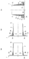
- FIG. 3 is an explanatory diagram showing a method for manufacturing a tube according to the first embodiment. It is explanatory drawing which shows the next process of FIG. It is explanatory drawing which shows the next process of FIG.
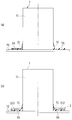
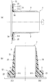
- FIG.14 (a) shows one process of manufacture of a short pipe
- FIG.14 (b) is explanatory drawing which shows the next process. It is explanatory drawing which shows the next process of FIG.14 (b). It is explanatory drawing which shows the next process of FIG. It is sectional drawing which shows the short tube which comprises the pipe
- FIG.18 (a) shows one process of manufacture of a short pipe
- FIG.18 (b) is explanatory drawing which shows the next process.
- FIG. 19A is an explanatory diagram showing the next step of FIG. 18B
- FIG. 19B is an explanatory diagram showing the next step.
- FIG.21 (a) shows one process of manufacture of a short pipe
- FIG.21 (b) is explanatory drawing which shows the next process.
- FIG. 22A is an explanatory diagram showing the next step of FIG. 21B
- FIG. 22B is an explanatory diagram showing the next step
- FIG. 22C is an explanation showing the next step.
- FIG. It is sectional drawing which shows the pipe
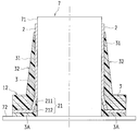
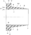
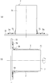
- FIG. 1 is a cross-sectional view showing a tube according to Embodiment 1 of the present invention
- FIG. 2 is a half cross-sectional view schematically showing a structure of an end portion of the tube.
- the tube 1 according to Embodiment 1 is formed as a multilayer tube including a soft layer 2 having wear resistance and impact resistance and a high-strength fiber reinforced resin layer 3.
- the soft layer 2 is formed in a substantially cylindrical shape on the inner peripheral side of the tube 1.
- the soft layer 2 is preferably made of a material having high strength and excellent wear resistance, and is made of a soft synthetic resin material such as polyurethane resin or polyethylene resin, or a rubber material.
- the soft synthetic resin material constituting the soft layer 2 preferably has an elastic modulus (tensile elastic modulus) at 25 ° C. of 150 MPa to 2500 MPa.
- the elastic modulus is preferably 1300 MPa to 2100 MPa, and the hardness is preferably 100 or less in terms of Rockwell hardness (R scale) based on JISK7202.
- R scale Rockwell hardness
- the elastic modulus is 1070 MPa to 1090 MPa and the hardness is 66 to 73 in Shore D hardness.
- the elastic modulus is preferably 180 MPa to 280 MPa, and the hardness is preferably 44 to 50 in Shore D hardness.
- the elastic modulus is 260 MPa to 520 MPa and the hardness is 55 to 56 in Shore D hardness.
- the rubber-based material forming the soft layer 2 preferably has a type A durometer hardness of 40 to 90 based on JISK6253.
- the elastic modulus of the rubber material is more preferably 1 MPa to 100 MPa.
- the soft layer 2 can be provided with sufficient wear resistance and durability that can withstand the contact impact of the abrasive fluid including earth and sand.
- the fiber reinforced resin layer 3 is composed of a fiber reinforced resin material (fiber reinforced composite material) in which a long fiber material 31 is impregnated with a thermosetting resin.
- a fiber reinforced resin material fiber reinforced composite material
- thermosetting resin that is the base material resin
- the long fiber material 31 that is the reinforcing material.
- thermosetting resin polyester, vinyl ester, epoxy, polypropylene, polyethylene, polyethylene terephthalate, polybutyl terephthalate resin, or the like can be used.
- the long fiber material 31 is preferably an inorganic fiber or an organic fiber having high strength and a high elastic modulus.
- fibers such as glass fiber, carbon fiber, and aramid fiber can be used.
- a woven fabric, a non-woven fabric, or a roving in which fibers are aligned is preferable.
- the tube 1 has a straight tubular main body portion 11 and flange portions 12 provided at both ends in the tube axis direction.
- the straight tubular body 11 includes a substantially cylindrical soft layer 2 on the inner peripheral side.
- the soft layer 2 constitutes the inner peripheral surface of the main body 11.
- a fiber reinforced resin layer 3 is provided on the outer peripheral side of the soft layer 2.
- the soft layer 2 and the fiber reinforced resin layer 3 in the main body 11 are formed with a substantially constant thickness over the entire length of the main body 11.
- the flange part 12 is provided in the both ends of the main-body part 11 in the shape of a bowl. As shown in an enlarged view in FIG. 2, the flange portion 12 is provided at the end portion of the tube 1 so as to project in the radial direction. Also in the flange part 12, the soft layer 2 is arrange
- the fiber reinforced resin layer 3 of the flange portion 12 is continuous with the fiber reinforced resin layer 3 of the main body portion 11 and extends outwardly in a bowl shape, and is integrally formed with the main body portion 11. Also on the inner peripheral side of the flange portion 12, the soft layer 2 is formed continuously from the main body portion 11. The end portion of the soft layer 2 has a diameter-expanded portion 21 that is expanded in the radial direction. The enlarged-diameter portion 21 is provided in a tapered shape that increases in diameter toward the end in the tube axis direction.
- the soft layer 2 is formed continuously on the inner peripheral side of the tube 1 as a whole, and the diameter is increased toward the end in the tube axis direction.
- the soft layer 2 enters the fiber reinforced resin layer 3 at the end of the tube 1, and the enlarged diameter portion 21 is embedded in the fiber reinforced resin layer 3.
- the outer peripheral surface, end surface, and inner peripheral surface of the enlarged diameter portion 21 are all surrounded by the fiber reinforced resin material constituting the fiber reinforced resin layers 3 and 3A and are integrally covered.
- cover the internal peripheral surface of the enlarged diameter part 21 are formed thickly as the edge part of a pipe-axis direction.
- the fiber reinforced resin layer 3 ⁇ / b> A is provided to be exposed on the inner peripheral surface of the flange portion 12.
- This fiber reinforced resin layer 3 ⁇ / b> A further covers the end face of the enlarged diameter portion 21 and constitutes the end face in the axial direction of the flange portion 12.
- the fiber reinforced resin layer 3 and the fiber reinforced resin layer 3A are shown separately, but the fiber reinforced resin layer 3A is a portion provided integrally with the fiber reinforced resin layer 3, and is a common fiber reinforced resin. Made of material.
- the inner peripheral surface of the tube 1 has a smooth cylindrical inner periphery in which the soft layer 2 continuous in the tube axis direction of the main body portion 11 and the fiber reinforced resin layer 3A constituting the inner peripheral surface of the flange portion 12 are continuous. A surface is formed.
- the water stop part 4 is provided on the end face in the axial direction of the flange part 12.
- the water stop part 4 is formed in an annular shape, and covers the flange end surface made of the above-described fiber reinforced resin material.
- the water stop portion 4 is formed of a soft synthetic resin material or a rubber material. The water stop portion 4 covers the end face of the flange portion 12 in the axial direction, and is bonded and fixed to the fiber reinforced resin layer 3A.
- a flexible sleeve 9 is attached to the flange portion 12 in order to connect the plurality of pipes 1 so as to be bent as shown in FIG.
- the flange portions 12 at both ends of the tube 1 are sandwiched between the joint flanges 91 of the flexible sleeve 9 and fixed by tightening the connecting bolts 92.
- the flange portion 12 is required to have sufficient strength. That is, high axial force and frictional force act on the flange portion 12, and also impact force from a fluid including earth and sand in the pipe, a dredge machine, and the like acts.
- the pipe 1 has the flange portion 12 integrally formed with the main body portion 11 by the fiber reinforced resin layer 3 of the short pipe 5, so that even if a large external force is applied, the pipe 1 is not damaged and the sand discharge It can be suitably used as a tube.
- the enlarged diameter portion 21 of the soft layer 2 is held by the fiber reinforced resin material constituting the fiber reinforced resin layers 3 and 3A. For this reason, even if an abrasive fluid including earth and sand contacts or collides with the inner peripheral surface of the tube 1, the end portion of the soft layer 2 that is easily peeled is covered with the fiber reinforced resin material and is firmly Since it is hold
- the pipe 1 in the underwater portion can be easily moved by being pulled up to the water surface by a crane or the like while being joined to the flexible sleeve 9. it can.
- the pipe 1 is much lighter than a conventional sand pipe made of steel pipe, has excellent durability and workability, and is hardly corroded. Therefore, it is possible to quickly and easily perform the removal work and the movement work of the pipe 1.
- the soot tube 1 is formed using a mold having a cylindrical outer peripheral surface and rotating around an axis.
- a manufacturing method of the pipe 1 using the plurality of short pipes 5 in which the short pipe 5 including the flange portion 12 is formed in advance will be described.
- FIG. 3 is a cross-sectional view showing an example of the short pipe 5 constituting the pipe 1.
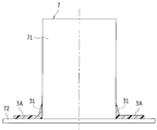
- FIG. 4 is an explanatory diagram showing one process of the manufacturing method of the short pipe 5
- FIGS. 5 to 7 are explanatory diagrams sequentially showing each process following the process of FIG.
- FIG. 8 is an explanatory view showing a manufacturing process of the pipe 1 using the manufactured short pipe 5
- FIG. 9 and FIG. 10 are explanatory views sequentially showing each process following FIG.
- the short pipe 5 is a pipe constituting a part of the pipe 1, and includes a flange portion 12 and a part of the main body portion 11 in the pipe 1.
- the fiber reinforced resin layer 3 constituting a part of the main body portion 11 has a tapered portion 32, and the outer peripheral surface is formed so as to be thickened toward the flange portion 12 side to become thicker.
- the soft layer 2 is provided on the inner peripheral side of the tapered portion 32 and the inside of the flange portion 12.
- the short tube 5 is formed using a short tube mold 7 illustrated in FIG.
- the short tube mold 7 includes a cylindrical portion 71 and a disc-shaped flange 72 at the lower end of the cylindrical portion 71.
- the short tube mold 7 is installed with the shaft in the vertical direction so that the cylindrical portion 71 is upward and the flange portion 72 is downward.
- the short tube mold 7 is preferably installed on a turntable (not shown) and is rotatable.
- a sheet-like long fiber material 31 is disposed along the upper surface of the collar portion 72 and the outer peripheral surface of the lower end portion of the cylindrical portion 71 with respect to the short pipe mold 7 installed in the collar.
- the laminated long fiber material 31 is impregnated with a thermosetting resin to form the fiber reinforced resin layer 3A.
- the laminated shape is laminated so that the length in the axial direction of the long fiber material 31 at the portion arranged on the outer peripheral surface of the cylindrical portion 71 is gradually shortened.
- the long fiber material 31 is laminated on the upper surface of the collar portion 72 so as to have a uniform thickness. As a result, as shown in FIG. 4, a fiber reinforced resin layer 3A having a tapered rise is formed.
- the axis of the short tube mold 7 is disposed sideways.
- the short tube mold 7 is rotated about its axis, and an uncured soft synthetic resin material or rubber-based material is discharged onto the outer peripheral surface of the rotating short tube mold 7.
- the discharge nozzle is moved along the axial direction from the flange portion 72 side of the short tube mold 7 toward the edge portion of the cylindrical portion 71. That is, the material is spirally supplied from the tapered outer peripheral surface of the fiber reinforced resin layer 3 ⁇ / b> A formed on the short tube mold 7 in the previous step to the outer peripheral surface of the cylindrical portion 71 of the short tube mold 7. Thereby, the substantially cylindrical soft layer 2 is formed.
- the soft layer 2 is formed in a tapered shape along the tapered surface of the fiber reinforced resin layer 3A at a portion near the flange portion 72 of the short tube mold 7. Thereby, the enlarged diameter part 21 is shape
- the soft layer 2 is formed in a substantially cylindrical shape on the outer peripheral surface of the cylindrical portion 71 of the short tube mold 7.
- the short pipe mold 7 is again arranged in the vertical direction.
- the fiber reinforced resin layer 3 is laminated and formed by a hand layup method.
- the long fiber material 31 is laminated in an inverted shape and impregnated with a thermosetting resin.
- the fiber reinforced resin layer 3 is laminated and formed so that the upper end portion of the soft layer 2 extends from the fiber reinforced resin material.
- the soft layer 2 is partially exposed from the upper end portion of the fiber reinforced resin layer 3.
- the long fiber material 31 is laminated
- positioned at the outer peripheral part of the cylindrical part 71 the length of the axial direction of the long fiber material 31 is shortened gradually, and a fiber layer is formed so that an outer layer may be laminated
- the taper part 32 is shape
- the fiber reinforced resin layer 3 is laminated on the upper part of the previously formed fiber reinforced resin layer 3A, and the flange portion 12 is integrally formed. Thereby, the continuous fiber reinforced resin layer 3 is formed in the upper part of the collar part 72 and the outer peripheral part of the cylindrical part 71. Thereafter, the short tube 5 as shown in FIG. 3 is obtained by demolding.
- fine pores for example, provided by the number of more than one location per the surface 1 m 2 of the soft layer 2 is preferably a through-hole or cut a size greater than 10 [mu] m.
- the soft layer 2 to have an air discharge function. Therefore, when the fiber reinforced resin layer 3 is laminated on the soft layer 2, there is no possibility that air is accumulated at the interface. Therefore, the interfacial adhesiveness between the soft layer 2 and the fiber reinforced resin layer 3 is improved, and peeling between layers can be prevented.
- the tube 1 is manufactured using the obtained short tube 5.
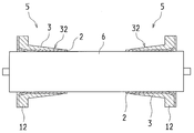
- two short tubes 5 are installed in a cylindrical or columnar rotating mold 6.
- the two short tubes 5 are arranged such that the flange portion 12 is positioned closer to the end of the rotary mold 6 and the tapered portions 32 of the short tube 5 are opposed to each other.
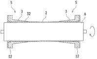
- the soft layer 2 is formed in the region between the short tube 5 and the short tube 5.
- An uncured soft synthetic resin material or rubber-based material is discharged while moving in the axial direction on the outer peripheral surface of the rotating mold 6 rotated around the axis. As a result, the uncured resin is discharged spirally on the outer peripheral surface of the rotating mold 6.
- a substantially cylindrical soft layer 2 is formed between the two short tubes 5 and 5 so as to be continuous with the soft layer 2.
- the fiber reinforced resin layer 3 of the main body 11 of the tube 1 is formed.
- a long fiber material 31 impregnated with a thermosetting resin is regularly and spirally wound from one short tube 5 to the other short tube 5.
- the fiber reinforced resin layer 3 is laminated in a tubular shape, continuously with the previously formed fiber reinforced resin layer 3 of the short tube 5.
- the long fiber material 31 (see FIG. 2) impregnated with the thermosetting resin is stacked on the outer peripheral surface of the fiber reinforced resin layer 3 of the short tube 5. Since the short pipe 5 is formed with the tapered portion 32, a sufficient bonding area between the previously formed fiber reinforced resin layer 3 and the subsequently formed fiber reinforced resin layer 3 is ensured. Therefore, the fiber reinforced resin layer 3 of the short tube 5 and the fiber reinforced resin layer 3 formed by lamination in this step are joined through a wide area and can be sufficiently bonded to enhance the integrity of both.
- the short tube 5 has the soft layer 2 extended from the tip of the fiber reinforced resin layer 3 and partially exposed.
- the soft layer 2 to be molded later can be reliably bonded to the soft layer 2 of the short tube 5, and the integrity of these can be improved.
- the water stop 4 is attached to the flange end face of the end in the tube axis direction and the mold is removed to obtain the tube 1.
- the flanged tube 1 having excellent lightness, durability, and corrosion resistance can be formed.
- the pipe 1 avoids peeling of the interface between the soft layer 2 and the fiber reinforced resin layer 3 while ensuring sufficient strength in the flange portion 12.
- the flange portion 12 is formed in advance on the short tube 5 and is formed by continuously forming the soft layer 2 and the fiber reinforced resin layer 3 of the main body portion 11 with respect to the short tube 5.
- the tube 1 can be formed in a state where a certain strength is ensured. Therefore, the tube 1 can be made excellent in any of rigidity, lightness, durability, wear resistance, and corrosion resistance, and is a tube suitable for transporting an abrasive fluid including earth and sand. It can be a body.
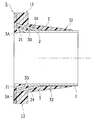
- FIG. 12 is a half sectional view showing an end structure of the tube 1 according to the second embodiment.
- FIG. 13 is a cross-sectional view showing the short tube 5 constituting the tube 1, and
- FIGS. 14 to 16 are explanatory views sequentially showing a method for manufacturing the short tube 5.
- the taper-shaped enlarged diameter part 21 was provided in the edge part of the soft layer 2.
- the soft layer 2 has the enlarged diameter portion 21 having a shape different from that of the first embodiment.
- the configuration of the soft layer 2 will be mainly described, and other configurations such as the fiber reinforced resin layer 3 and the main body 11 are the same as those of the first embodiment, and therefore, the same reference numerals as those of the first embodiment are used. Detailed description will be omitted.
- the tube 1 according to the second embodiment is provided with the diameter-expanded portion 21 of the soft layer 2 extending to the outer peripheral edge portion of the flange portion 12.
- the diameter-enlarged portion 21 has a soft layer 2 continuous from the main body portion 11 having an enlarged diameter at the end, a tapered first enlarged-diameter portion 211, and a second extended from the end of the first enlarged-diameter portion 211. And an enlarged diameter portion 212.
- the first enlarged diameter portion 211 is formed so as to increase in diameter toward the end in the tube axis direction.
- the second enlarged diameter portion 212 is formed to project outward in a bowl shape.
- the widened diameter portion 21 is integrally held by the fiber reinforced resin material constituting the fiber reinforced resin layers 3 and 3A.
- the inner peripheral side of the enlarged diameter portion 21 is covered with the fiber reinforced resin layer 3A.
- the fiber reinforced resin layer 3A is formed thicker toward the end in the tube axis direction.
- Both the first enlarged diameter portion 211 and the second enlarged diameter portion 212 are in close contact with the fiber reinforced resin material constituting the fiber reinforced resin layers 3, 3 ⁇ / b> A, and are integrally held inside the flange portion 12.
- the inner peripheral surface of the tube 1 has a smooth cylindrical inner periphery in which the soft layer 2 continuous in the tube axis direction of the main body portion 11 and the fiber reinforced resin layer 3A constituting the inner peripheral surface of the flange portion 12 are continuous. A surface is formed.
- the tube 1 having such a configuration can be manufactured using the short tube 5 shown in FIG.
- the short pipe 5 is a pipe constituting a part of the pipe 1, and includes a flange portion 12 in the pipe 1 and a part of the main body portion 11.
- the fiber reinforced resin layer 3 constituting a part of the main body portion 11 has a tapered portion 32, and the outer peripheral surface is formed so as to be thickened toward the flange portion 12 side to become thicker. .
- a sheet-like long fiber material 31 is laminated on a short tube mold 7 having a shaft installed vertically so that the collar portion 72 faces downward, and fibers are obtained by a hand lay-up method.
- the reinforced resin layer 3A is molded.
- the laminated shape is laminated so that the length in the axial direction of the long fiber material 31 at the portion arranged on the outer peripheral surface of the cylindrical portion 71 is gradually shortened.
- the soft layer 2 is formed above the flange portion 72 of the short tube mold 7.
- the soft layer 2 is formed by rotating the short tube mold 7 or rotating the resin discharge port to discharge an uncured soft synthetic resin material or rubber-based material around the cylindrical portion 71. Thereby, the 2nd enlarged diameter part 212 of the soft layer 2 is formed.
- the shaft of the short pipe mold 7 is disposed sideways.
- an uncured soft synthetic resin material or rubber-based material is discharged onto the outer peripheral surface of the short tube mold 7 that rotates about the axis, and the soft layer 2 continues to the second enlarged diameter portion 212. Is molded.
- the soft layer 2 is formed in a tapered shape along the tapered surface of the fiber reinforced resin layer 3 ⁇ / b> A.
- the 1st enlarged diameter part 211 integral with the 2nd enlarged diameter part 212 is shape
- the short tube mold 7 is again placed in the vertical direction, and the fiber reinforced resin layer 3 is laminated and formed by the hand lay-up method. Also in this case, the fiber reinforced resin layer 3 is formed by extending the upper end of the soft layer 2 beyond the upper end of the long fiber material 31. In the portion arranged on the outer peripheral portion of the cylindrical portion 71, the length of the long fiber material 31 in the axial direction is gradually shortened to form a fiber layer, and the tapered portion 32 is formed. The fiber reinforced resin layer 3 is laminated on the upper part of the previously formed fiber reinforced resin layer 3A via the enlarged diameter portion 21, and is integrally formed. Thereby, the short tube 5 as shown in FIG. 13 is obtained.
- the tube 1 is formed using the two short tubes 5 by the same procedure as in the first embodiment.
- a water stop portion 4 is provided on the end surface of the flange portion 12 to obtain the pipe 1.
- the soft layer 2 and the fiber reinforced resin layer 3 can be integrated.
- the soft layer 2 is provided with a first enlarged diameter portion 211 and a second enlarged diameter portion 212, which are sandwiched and held integrally by the fiber reinforced resin layers 3, 3A, so that peeling of the interface is avoided. It is possible to obtain a tubular body suitable for transferring an abrasive fluid including earth and sand.
- FIG. 17 is a cross-sectional view showing a part of the pipe 1 according to the third embodiment and showing the short pipe 5 constituting the pipe 1.
- 18 and 19 are explanatory views sequentially showing a method for manufacturing the short pipe 5.
- FIG. 17 is a cross-sectional view showing a part of the pipe 1 according to the third embodiment and showing the short pipe 5 constituting the pipe 1.
- 18 and 19 are explanatory views sequentially showing a method for manufacturing the short pipe 5.
- an anchor portion 23 is further provided on the diameter-expanded portion 21 having the same shape as that of the second embodiment.
- the structure of the fiber reinforced resin layer 3, the main body part 11, etc. is the same as that of Embodiment 2, it shows using the same code
- the diameter-expanded portion 21 of the soft layer 2 is extended to the outer peripheral edge portion of the flange portion 12 in the short tube 5.
- the enlarged diameter portion 21 has a tapered first enlarged diameter portion 211 and a second enlarged diameter portion 212 extending in a bowl shape.
- An anchor portion 23 is provided on the second enlarged diameter portion 212.
- the second enlarged-diameter portion 212 projecting outward in a bowl shape is integrally provided with an anchor portion 23 at the periphery.
- the anchor portion 23 is formed on one surface (surface opposite to the end surface) of the second enlarged diameter portion 212 so as to protrude along the tube axis direction in the direction of the main body portion 11 of the tube 1. Further, the anchor portion 23 is provided so as to be continuous in the circumferential direction and border the peripheral portion of the second enlarged diameter portion 212.
- the anchor portion 23 is held and integrated with a fiber reinforced resin material constituting the fiber reinforced resin layer 3.
- the tube 1 is manufactured using the short tube 5 configured as described above. As shown in FIG. 18 (a), the sheet-like long fiber material 31 is laminated on the short tube mold 7 in which the shaft is installed vertically so that the flange portion 72 is positioned downward, and by the hand lay-up method, The fiber reinforced resin layer 3A is molded.
- the soft layer 2 is formed above the flange portion 72 of the short tube mold 7.
- the soft layer 2 is formed by rotating the short tube mold 7 or rotating the discharge nozzle and discharging an uncured soft synthetic resin material or rubber-based material around the cylindrical portion 71.
- the 2nd enlarged diameter part 212 is shape
- the anchor portion 23 is formed by discharging the material in an annular shape on the peripheral edge of the second enlarged diameter portion 212.
- a tapered first enlarged diameter portion 211 is formed at a portion near the flange portion 72 of the short tube mold 7.
- the short tube mold 7 is placed again in the vertical direction, and the fiber reinforced resin layer 3 is laminated by the hand lay-up method.
- the anchor portion 23 is embedded by the fiber reinforced resin layer 3 laminated above the second enlarged diameter portion 212.
- the lengths in the axial direction of the long fiber material 31 disposed on the outer peripheral portion of the cylindrical portion 71 are gradually shortened and the tapered portion 32 is formed on the outer peripheral portion of the cylindrical portion 71. Thereby, the short tube 5 as shown in FIG. 17 is obtained.
- the main body portion 11 is formed using the two short pipes 5, the water stop portion 4 is provided on the end face of the flange portion 12, and the pipe 1 is obtained.
- the diameter-expanded portion 21 and the anchor portion 23 of the soft layer 2 enter the fiber-reinforced resin layer 3 side and are firmly held.
- the integrity of the resin layer 3 is enhanced.
- FIG. 20 is a cross-sectional view showing a part of the pipe 1 according to the fourth embodiment and showing the short pipe 5 constituting the pipe 1.
- 21 and 22 are explanatory views sequentially showing a method for manufacturing the short pipe 5.
- the tube 1 according to the present embodiment includes an anchor portion 24 in the soft layer 2, and the shape of the anchor portion 24 is different from that of the third embodiment.
- the structure of the fiber reinforced resin layer 3, the main body part 11, etc. is the same as that of Embodiment 1, it shows using the same code
- the tube 1 is provided with a tapered diameter-expanded portion 21 at the end of the soft layer 2 in the short tube 5.
- An anchor portion 24 extending outward is provided on the outer peripheral surface of the soft layer 2.
- the anchor portion 24 is formed in a taper shape that is continuous in the circumferential direction of the soft layer 2 and expands toward the end in the tube axis direction.
- the anchor portion 24 is provided in a tapered shape on the outer peripheral side of the enlarged diameter portion 21 and substantially parallel to the enlarged diameter portion 21.
- the anchor part 24 of the soft layer 2 is formed in the double taper shape inside and outside with the enlarged diameter part 21.
- the anchor portion 24 is held by the fiber reinforced resin material constituting the fiber reinforced resin layer 3 (3A, 3B) and is firmly integrated.
- Tube 1 is manufactured using short tube 5.
- a sheet-like long fiber material 31 is laminated on a short pipe mold 7 having a shaft installed vertically so that the collar portion 72 faces downward, and a hand lay-up method is performed.
- the fiber reinforced resin layer 3A at the tube end is formed.
- the shaft of the short tube mold 7 is disposed sideways, and an uncured soft synthetic resin material or rubber-based material is discharged onto the outer peripheral surface of the short tube mold 7.
- a substantially cylindrical soft layer 2 is formed.
- the tapered diameter-increased portion 21 is formed in the portion near the flange portion 72 of the short tube mold 7.
- the fiber reinforced resin layer 3B is laminated and formed by the hand lay-up method while the short pipe mold 7 is placed sideways. At this time, the fiber reinforced resin layer 3B is formed so as to cover the outer peripheral portion of the enlarged diameter portion 21 formed in the previous step.
- the fiber reinforced resin layers 3, 3A, 3B are formed of a common fiber reinforced resin material.
- the soft tube formed earlier so as to cover the outer peripheral surface of the fiber reinforced resin layer 3B formed in the previous step in a state where the short tube mold 7 is rotated around the axis.
- the material common to the layer 2 is discharged.
- the fiber reinforced resin layer 3B and the soft layer 2 are formed.
- the said material is discharged so that the area
- an integral anchor portion 24 that is continuous with the soft layer 2 in a tapered shape is formed.
- the shaft of the short tube mold 7 is installed in the vertical direction, and the fiber reinforced resin layer 3 is laminated by the hand lay-up method.
- a tapered portion 32 is formed on the fiber reinforced resin layer 3.
- the main body part 11 is formed using the two short pipes 5 by the same procedure as in the first embodiment, and the water stop part 4 is provided on the end face of the flange part 12 to obtain the pipe 1.
- the diameter-expanded portion 21 and the anchor portion 24 of the soft layer 2 are firmly held by the fiber reinforced resin layers 3, 3A, and 3B, and the integrity is further improved. Since the anchor portion 24 is formed in a taper shape, a sufficient adhesion area with the fiber reinforced resin layers 3 and 3B is secured, and the fiber reinforced resin layers 3, 3A and 3B and the soft layer are coupled with the action of the enlarged diameter portion 21. 2 is reliably integrated. Thereby, even if the inner peripheral surface of the pipe 1 is subjected to a collision impact of the abrasive fluid, the integrity of each layer is sufficiently maintained, and the interface can be prevented from peeling off.
- the tube 1 according to the present invention can be implemented in various other forms besides the above embodiment.
- the pipe 1 described as a form of a flanged pipe it is not limited to a configuration with a flange, and may be a straight tubular body or a bent pipe, Any other shape of tube may be used.
- an effective tube 1 may be constructed. Further, for example, the tube 1 may be configured as shown in FIG.
- This pipe 1 has mutually different structures at both ends having a flange portion 12.
- One end portion 1A employs one of the structures described in the above embodiment (the structure of Embodiment 1 in FIG. 23).
- the other end portion 1B has an end surface made of a soft synthetic resin that is continuous with the soft layer 2 on the inner peripheral surface on the end surface of the flange portion 12.
- the end portion 1B is configured by a short tube 5 formed in advance, like the tube 1 described in the above embodiment.
- the soft layer 2 that covers the inner peripheral surface of the fiber reinforced resin layer 3 and the soft layer 2 that covers the end surface of the flange portion 12 are continuously formed integrally.
- the soft layer 2 on the end face of the flange portion 12 functions as a water stop portion.
- the pipe 1 As the sand discharge pipe, it is preferable to use the pipe 1 with the end 1B of such a structure arranged on the downstream side and the end 1A arranged on the upstream side.
- the pipe 1 is susceptible to the influence of the abrasive fluid on the upstream end 1A, but the upstream end 1A has a structure in which the interface of each layer is difficult to peel off.
- the manufacturing cost can be reduced with a simpler structure.
- the enlarged diameter portion 21 at the end of the soft layer 2 is not limited to the shape described above, and for example, the enlarged diameter portion is further expanded in the axial direction so as to span the main body portion 11 and the flange portion 12. May be.
- the shape of the anchor portions 23 and 24 is not limited to the above-described shape as long as it is a shape that is integrally held in the fiber reinforced resin layer, and the number of the portions may be increased or the arrangement location may be changed. May be. Therefore, the above-described embodiment is merely an example and is not limited.
- the fiber reinforced resin layers 3, 3 ⁇ / b> A, and 3 ⁇ / b> B described in the above embodiment are shown separately for convenience of description, and the boundary is shown by a solid line in the drawing, but these are substantially integrated as a molded product. It is inseparable and formed continuously.
- each part such as the soft layer 2 and the anchor part 24 is shown separately for convenience of explanation, and the boundary is shown by a solid line in the drawing. However, as a molded product, these are substantially inseparable and formed continuously. It is what is done.
- the tube 1 according to the present invention has a significantly improved integrity between the soft layer 2 and the fiber reinforced resin layer 3, and has rigidity, lightness, durability, wear resistance, and resistance. It can be set as the tubular body excellent in all corrosiveness.
- the pipe 1 is used as a sand discharge pipe, the weight is greatly reduced as compared with the conventional steel pipe, so that the pipe 1 and the flexible sleeve 9 arranged over a long distance can be transferred while being joined. It becomes easy, the work process is simplified, and the number of workers and the work time can be reduced. Even if the pipe 1 is installed in the water for a long period of time, it does not corrode, has sufficient durability, and can extend the period required for replacement, so that the cost can also be greatly reduced. .
- the present invention can be suitably used as a tube used to transport a fluid having wear properties.
Landscapes
- Engineering & Computer Science (AREA)
- General Engineering & Computer Science (AREA)
- Mechanical Engineering (AREA)
- Rigid Pipes And Flexible Pipes (AREA)
- Protection Of Pipes Against Damage, Friction, And Corrosion (AREA)
Abstract
管(1)は、軟質層(2)と繊維強化樹脂層(3)とを備える。軟質層(2)は、軟質合成樹脂系材料またはゴム系材料により形成されている。繊維強化樹脂層(3)は、熱硬化性樹脂を母材樹脂としている。管(1)は、管軸方向の中間部では、繊維強化樹脂層(3)が軟質層(2)の外周側に積層されている。管軸方向の少なくとも一方の端部では、軟質層(2)は外方に拡張された拡径部(21)を有する。拡径部(21)は繊維強化樹脂層(3)に埋設され、繊維強化樹脂層(3)を構成する繊維強化樹脂材に保持されている。
Description
本発明は、軟質層と繊維強化樹脂層とを有する管に関する。
従来から、港湾や航路等の浚渫には、水底から採取する土砂の種類や採取の方法等によって各種の方式が採用されている。特に砂地の浚渫には、浚渫土量の大きいポンプ方式が適するとして多用されている。ポンプ方式は、ポンプ船に備えられた吸水管で水底の土砂を水とともに吸い上げ、水と混合した状態の土砂を、水中や地上に配設した排砂管を経由して、埋め立て地や土砂捨場等の適宜の場所に移送するものである。
この種の排砂管には、高い強度を有する鋼管が広く用いられてきた。鋼管同士の接合部には、排砂管を折曲自在に支持するためにゴム材からなる可撓性スリーブが備えられる。これにより、排砂管のフランジ部(ルーズフランジ型)と可撓性スリーブの継手フランジ部(固定フランジ型)とが、連結ボルトにより連結されるように構成されている(例えば、特許文献1参照。)。
長距離にわたって配設される排砂管は、浚渫対象域の変更に際しては、排砂管と可撓性スリーブとを接合した状態のまま、クレーン等により水中から引き上げられて移設される。このとき、鋼管の重量が大きいことから大型の重機を必要とするうえ、作業工程が煩雑であって、作業人数および作業時間を要するものとなっていた。
また、水底に設置されていた排砂管は、腐食して脆くなっており、可撓性スリーブを取り外す際や、撤去作業を行う際に破損しやすく、新たな排砂管に交換しなければならないことが多かった。近年では、建設土木資材の価格が高騰し、鋼管からなる排砂管の価格も上昇しており、新たな排砂管に交換すると、交換作業の手間に加えて新たな排砂管のために多大な費用が必要になるという問題点があった。
そこで、従来の鋼管からなる排砂管にかえて、軽量で作業性に富み、材料コストの低減を図ることのできる合成樹脂製の排砂管の開発が望まれた。しかし、排砂管を合成樹脂製のものとする場合、鋼管に劣らない十分な強度と、土砂等を含む流体によっても摩耗しにくい耐久性とを確保することが大きな課題点であった。
これに対し、本出願人は、特許文献2に開示されるように、耐摩耗性を有する軟質合成樹脂層を内周面に設け、繊維強化樹脂層を外周面に設けて、剛性および耐久性を高めたフランジ付き複層管を提案している。
特許文献2に記載の複層管にあっては、軟質合成樹脂層によって耐摩耗性を確保することができ、繊維強化樹脂層によって強度を確保することができる。また、複層管の直管部分のみならず、フランジ部においても十分な強度を有している。そのため、土砂等を含む摩耗性流体を移送するのに適しているものの、次に述べるような点において未だ改良の余地があった。
複層管を排砂管として用いる場合、当該管の内周面は土砂等を含む摩耗性流体から衝突衝撃を受ける。フランジ部の端面には、内周側の軟質合成樹脂層と繊維強化樹脂層との界面が現れている。そのため、これら各層の界面は摩耗性流体からの衝撃により離間しやすくなり、軟質合成樹脂層が剥がれやすくなるということが懸念された。
本発明は、上記のような問題点に鑑みてなされたものであり、その目的とするところは、管を構成する層間相互の一体性を高め、剛性、軽量性、耐久性、耐摩耗性、および耐腐食性のいずれにも優れた管を提供することにある。
前記の目的を達成するため、本発明の解決手段は、軟質層と繊維強化樹脂層とを有する管として、前記繊維強化樹脂層は、熱硬化性樹脂を母材樹脂とし、前記軟質層は、軟質合成樹脂系材料またはゴム系材料により形成する。管軸方向の中間部では、前記繊維強化樹脂層を、前記軟質層の外周側に積層する。また、管軸方向の少なくとも一方の端部では、前記軟質層に、外方に拡張する拡径部を備えさせ、該拡径部を前記繊維強化樹脂層に埋設し、前記繊維強化樹脂層を構成する繊維強化樹脂材に拡径部が保持されるように構成する。
このような特定事項により、軟質層は管の耐摩耗性を確保し、繊維強化樹脂層は高い強度を確保する。したがって、剛性、軽量性、耐久性、耐腐食性、および耐摩耗性のいずれにも優れた管とすることができる。軟質層の拡径部は、繊維強化樹脂層を構成する繊維強化樹脂材に保持されているので、軟質層の端部は露出せず、繊維強化樹脂層に一体化される。そのため、軟質層に流体が作用しても、軟質層と繊維強化樹脂層との一体性が維持される。これにより、軟質層が繊維強化樹脂層から剥離するのを防止でき、長期的に良好な状態を保つことができる。
より具体的な構成として次のものが挙げられる。まず、前記拡径部の内周面は、前記繊維強化樹脂層を構成する繊維強化樹脂材により被覆され、この被覆している繊維強化樹脂材が、管軸方向の端部ほど厚肉状に形成されることが好ましい。
これにより、軟質層の拡径部の内周面は繊維強化樹脂層を構成する繊維強化樹脂材に一体的に覆われる。また、前記管の少なくとも一方の端部は、軟質層と繊維強化樹脂材とが連続し、滑らかに接続された内周面を有するものとなる。したがって、軟質層と繊維強化樹脂層との一体性が十分に確保される。
また、前記軟質層は、外方へ突出するアンカー部を備えていることが好ましい。
これにより、前記拡径部に加えて、アンカー部が繊維強化樹脂層を構成する繊維強化樹脂材に保持され、軟質層と繊維強化樹脂層の一体性がより一層高められる。
また、前記アンカー部は、前記拡径部の端縁部に設けられることが好ましい。
これにより、前記拡径部の端縁部が繊維強化樹脂材に保持されて、管端部における軟質層と繊維強化樹脂層との一体性が十分に確保される。
あるいは、前記アンカー部は、周方向に連続し、管軸方向の端部ほど拡径するテーパー状に形成されてもよい。
これにより、テーパー状のアンカー部が繊維強化樹脂材に保持されて、管端部における軟質層と繊維強化樹脂層との一体性がより一層向上する。
また、前記構成の管にあって、管軸方向の両端部に鍔状にフランジ部を設け、前記拡径部を、フランジ部の内部まで延設した構成とすることが好ましい。
これにより、土砂等を含む摩耗性流体からの衝撃力が作用する排砂管にも好適な管とすることができ、軟質層と繊維強化樹脂層との一体性が十分に確保され、強度、軽量性、耐久性、および耐腐食性のいずれにも優れたフランジ付き管を構成することができる。
また、前記構成の管にあって、管軸方向の他方の端部では、前木繊維強化樹脂層を前記軟質層の外周側に積層し、前記軟質層が該端部の内周面から端面までを一体的に被覆した構成とすることが好ましい。
これにより、軟質層と繊維強化樹脂層との一体性を向上させるとともに、管同士の接合部の止水性を高めることができる。
本発明により、軟質層と繊維強化樹脂層とを有する管の剛性、軽量性、耐久性、耐摩耗性、および耐腐食性のいずれをも向上させることができる。また、軟質層と繊維強化樹脂層との一体性を格段に高めることができるので、これらの界面の相互間が剥離するのを効果的に防止し、長期的に安定して利用することが可能となり、摩耗性流体等を移送するのに好適なものとすることができる。
以下、本発明の実施の形態に係る管について、図面を参照しつつ説明する。
(実施形態1)
図1は、本発明の実施形態1に係る管を示す断面図であり、図2は、管の端部の構造を模式的に示す半断面図である。
図1は、本発明の実施形態1に係る管を示す断面図であり、図2は、管の端部の構造を模式的に示す半断面図である。
実施形態1に係る管1は、耐摩耗性および耐衝撃性を有する軟質層2と、高強度の繊維強化樹脂層3とを備えた複層管として形成されている。
軟質層2は、管1の内周側に略筒状に形成されている。この軟質層2は、高強度で耐摩耗性に優れた材質であることが好ましく、ポリウレタン樹脂、ポリエチレン系樹脂等の軟質合成樹脂系材料、またはゴム系材料により形成されている。
軟質層2を構成する軟質合成樹脂系材料としては、25℃での弾性率(引張弾性率)が150MPa~2500MPaであることが好ましい。例えば、軟質層2の軟質合成樹脂系材料は、ポリウレタンであれば、弾性率が1300MPa~2100MPaであり、硬さがJISK7202に基づくロックウェル硬度(Rスケール)で100以下であることが好ましい。高密度ポリエチレン(HDPE)であれば、弾性率が1070MPa~1090MPaであり、硬さがショアD硬度で66~73であることが好ましい。中密度ポリエチレン(MDPE)または低密度ポリエチレン(LDPE)であれば、弾性率が180MPa~280MPaであり、硬さがショアD硬度で44~50であることが好ましい。また、リニア低密度ポリエチレン(L―LDPE)であれば、弾性率が260MPa~520MPaであり、硬さがショアD硬度で55~56であることが好ましい。
軟質層2を形成するゴム系材料としては、硬さがJISK6253に基づくタイプAデュロメータ硬度が40~90であることが好ましい。ゴム系材料の弾性率は、1MPa~100MPaであるとより好ましい。
これにより、軟質層2には、土砂等を含む摩耗性流体の接触衝撃に耐えうる十分な耐摩耗性と耐久性とを備えさせることができる。
繊維強化樹脂層3は、長繊維材料31に熱硬化性樹脂を含浸させた繊維強化樹脂材(繊維強化複合材料)により構成されている。母材樹脂である熱硬化性樹脂と、補強材である長繊維材料31の組合せは多様である。
好ましい例を挙げると、熱硬化性樹脂としては、ポリエステル、ビニルエステル、エポキシ、ポリプロピレン、ポリエチレン、ポリエチレンテレフタレート、ポリブチルテレフタレート樹脂等を用いることができる。長繊維材料31には、高強度であり高弾性率を有する無機繊維や有機繊維が好ましく、例えば、ガラス繊維、炭素繊維、アラミド繊維等の繊維を用いることができる。繊維の形態としては、織布、不織布、または繊維を引き揃えたロービング等が好ましい。
図1に示すように、管1は、直管状の本体部11と、管軸方向の両端部に設けられたフランジ部12とを有する。
直管状の本体部11は、内周側に略筒状の軟質層2を備えている。軟質層2は本体部11の内周面を構成している。軟質層2の外周側には、繊維強化樹脂層3が設けられている。本体部11における軟質層2および繊維強化樹脂層3は、本体部11の全長にわたり、ほぼ一定の厚みで形成されている。
本体部11の両端部には、フランジ部12が鍔状に設けられている。図2に拡大して示すように、フランジ部12は管1の端部に径方向に張り出して設けられている。フランジ部12においても、内周寄りに軟質層2が配設され、外周寄りに繊維強化樹脂層3が配設されている。
フランジ部12の繊維強化樹脂層3は、本体部11の繊維強化樹脂層3から連続し、外方へ鍔状に張り出して本体部11と一体に形成されている。フランジ部12の内周側においても、軟質層2は本体部11から連続して形成されている。軟質層2の端部は、径方向に拡張された拡径部21を有している。拡径部21は、管軸方向の端部ほど拡径するテーパー状に設けられている。
これにより、軟質層2は、全体として、管1の内周側に連続して形成され、管軸方向の端部へ行くほど拡径されて形成されている。軟質層2は、管1の端部では、繊維強化樹脂層3側へ入り込み、拡径部21が繊維強化樹脂層3に埋設されている。
図2に示すように、拡径部21の外周面、端面、および内周面はいずれも繊維強化樹脂層3、3Aを構成する繊維強化樹脂材に取り囲まれ、一体的に被覆されている。拡径部21の内周面を被覆する繊維強化樹脂層3Aは、管軸方向の端部ほど厚肉状に形成されている。繊維強化樹脂層3Aは、フランジ部12の内周面に露出して設けられている。この繊維強化樹脂層3Aは、さらに拡径部21の端面を被覆し、フランジ部12の軸方向の端面を構成している。なお、説明の便宜上、繊維強化樹脂層3と繊維強化樹脂層3Aとを区別して示すが、繊維強化樹脂層3Aは繊維強化樹脂層3と一体的に設けられる部分であり、共通の繊維強化樹脂材からなる。
このように拡径部21は繊維強化樹脂材に埋設されており、軟質層2の端部が、管1の端部の内周面に露出せず、繊維強化樹脂層3、3Aに一体に保持されている。管1の内周面は、本体部11の管軸方向に連続する軟質層2と、フランジ部12の内周面を構成する繊維強化樹脂層3Aとが連続し、平滑な円筒状の内周面を形成している。
フランジ部12の軸方向の端面には、止水部4が備えられている。止水部4は、円環状に形成され、上述した繊維強化樹脂材からなるフランジ端面を被覆している。止水部4は、軟質合成樹脂材またはゴム系材料から形成されている。止水部4は、フランジ部12の軸方向の端面を被覆し、繊維強化樹脂層3Aに接着固定されている。
管1を排砂管として用いる場合、図11に示すように、複数の管1を折曲自在に連結するために、フランジ部12に可撓性スリーブ9を取り付ける。管1の両端部のフランジ部12は、可撓性スリーブ9の継手フランジ91に挟持され、連結ボルト92を締め付けて固定される。このため、フランジ部12には十分な強度を有することが求められる。つまり、フランジ部12には、高い軸方向力および摩擦力が作用し、また、管内の土砂を含む流体や浚渫機械等からの衝撃力も作用する。これに対し、管1は、フランジ部12が短管5の繊維強化樹脂層3により本体部11に一体的に形成されたので、大きな外力が作用しても、破損することはなく、排砂管として好適に使用することができる。
管1の端部では、軟質層2の拡径部21が繊維強化樹脂層3、3Aを構成する繊維強化樹脂材により保持されている。このため、管1の内周面に、土砂等を含む摩耗性流体が接触したり衝突したりしても、剥離しやすい軟質層2の端部は、繊維強化樹脂材に被覆されて強固に保持されているので、軟質層2と繊維強化樹脂層3、3Aとの一体性が保たれる。また、拡径部21がテーパー状であることにより、軟質層2と繊維強化樹脂層3との接合面積が十分に確保され、界面の剥離を生じにくく、管1を長期間にわたって安定的に使用することが可能となる。
所定箇所の浚渫を終えて次の浚渫箇所へ移動する場合には、水中部分の管1を可撓性スリーブ9と接合した状態のまま、クレーン等により水面に引き上げて、容易に移動させることができる。管1は、従来の鋼管からなる排砂管に比べて、格段に軽量化されており、耐久性および作業性に優れ、腐食しにくいものである。そのため、管1の撤去作業や移動作業を迅速かつ容易に行うことが可能となる。
(製造方法)
次に、管1の製造方法について説明する。
次に、管1の製造方法について説明する。
管1は、円柱状外周面を有して軸まわりに回転する金型を用いて成形される。管1の製造方法の一例として、以下に示す形態では、フランジ部12を備える短管5をあらかじめ形成し、複数の短管5を用いた管1の製造方法について説明する。
図3は、管1を構成する短管5の一例を示す断面図である。図4は、短管5の製造方法の一工程を示す説明図であり、図5~図7は、図4の工程に続く各工程を順に示した説明図である。図8は、製造した短管5を用いた管1の製造工程を示す説明図であり、図9および図10は、図8に続く各工程を順に示した説明図である。
図3に示すように、短管5は、管1の一部を構成する管であり、管1におけるフランジ部12と、本体部11の一部を備えている。短管5において、本体部11の一部を構成する繊維強化樹脂層3はテーパー部32を有し、外周面がフランジ部12側ほど拡径されて厚肉状となるように形成されている。テーパー部32の内周側およびフランジ部12の内部には軟質層2が設けられている。
短管5は、図4に例示する短管用金型7を用いて形成される。短管用金型7は、円筒部71と、円筒部71の下端部の円盤状の鍔部72とを有する。
まず、短管用金型7を、円筒部71が上方、鍔部72が下方となるように軸を縦向きにして設置する。短管用金型7は、図示しない回転台に設置して回転自在とされることが好ましい。
設置した短管用金型7に対し、鍔部72の上面と、円筒部71の下端部の外周面に沿って、シート状の長繊維材料31を配設する。ハンドレイアップ法により、積層した長繊維材料31に熱硬化性樹脂を含浸させ繊維強化樹脂層3Aを成形していく。積層形状は、円筒部71の外周面に配置する部分の長繊維材料31の軸方向の長さが徐々に短くなるように積層する。鍔部72の上面には均一な厚みとなるように長繊維材料31を積層する。これにより、図4に示すようにテーパー形状の立ち上がりを有する繊維強化樹脂層3Aが形成される。
次いで、図5に示すように、短管用金型7の軸を横向きに配置する。短管用金型7を軸まわりに回転させ、回転する短管用金型7の外周面に、未硬化の軟質合成樹脂材料またはゴム系材料を吐出する。このとき、短管用金型7の鍔部72側から円筒部71の端縁部の方向に、軸方向に沿って吐出ノズルを移動させる。すなわち、前工程で短管用金型7上に形成した、繊維強化樹脂層3Aのテーパー状の外周面から、短管用金型7の円筒部71の外周面にかけて材料を螺旋状に供給する。これにより、略筒状の軟質層2を成形する。
この軟質層2は、短管用金型7の鍔部72寄りの部分で、繊維強化樹脂層3Aのテーパー面に沿ってテーパー状に形成される。これにより、拡径部21が成形される。これに対し、短管用金型7の円筒部71の外周面には、軟質層2が略円筒状に成形される。
次いで、図6に示すように、短管用金型7を再び縦向きに配置し直す。ハンドレイアップ法により繊維強化樹脂層3を積層形成する。短管用金型7に形成した繊維強化樹脂層3Aと軟質層2の上に、長繊維材料31を鍔返し状に積層し、熱硬化性樹脂を含浸させる。この繊維強化樹脂層3は、軟質層2の上端部が、繊維強化樹脂材から延出するように積層形成する。軟質層2は、繊維強化樹脂層3の上端部から部分的に露出する。
さらに、図7に示すように、長繊維材料31を積層し、繊維強化樹脂層3を成形する。ここで、円筒部71の外周部に配置する部分では、長繊維材料31の軸方向の長さを徐々に短くし、内層よりも外層が低く積層されるように繊維層を形成する。これにより、短管用金型7の円筒部71の外周部にテーパー部32を成形する。先に成形した繊維強化樹脂層3Aの上部には繊維強化樹脂層3が積層され、フランジ部12が一体的に成形される。これにより、鍔部72の上部と円筒部71の外周部には、連続する繊維強化樹脂層3が形成される。その後、脱型することにより、図3に示したような短管5が得られる。
なお、上記の工程において、軟質層2を成形した後、軟質層2の表裏に貫通する多数の微小な孔を形成し、次工程の繊維強化樹脂層3の成形を行うようにしてもよい。この場合、微小な孔は、例えば、軟質層2の表面1m2当たり1箇所以上の数で設けられて、10μm以上の大きさである貫通孔または切れ目であることが好ましい。
これによって、軟質層2に空気排出機能をもたせることができる。そのため、軟質層2に繊維強化樹脂層3を積層したとき、界面に空気が溜まるおそれがなくなる。したがって、軟質層2と繊維強化樹脂層3との界面接着性が高められ、層間の剥離を防止することができる。
かかる界面接着性について、上記の多数の微小な孔を設けた軟質層2と、繊維強化樹脂層3との界面における接着性能試験を行った。その結果、軟質層2と繊維強化樹脂層3との接着強度が、微小な孔を設けない場合に比べて50%以上向上することが確認された。なお、微小な孔の径が10μm未満である場合には、軟質層2と繊維強化樹脂層3との間に溜まった空気の排出が不十分となり、良好な接着性が得られない可能性がある。
次いで、得られた短管5を用いて、管1を製造する。図8に示すように、2つの短管5を、円筒状または円柱状の回転金型6に設置する。2つの短管5は、それぞれ、フランジ部12が回転金型6の端部寄り位置し、短管5のテーパー部32同士が対向するように配置する。
次いで、図9に示すように、短管5と短管5との間の領域において、軟質層2を成形する。軸まわりに回転させた回転金型6の外周面に、未硬化の軟質合成樹脂材料またはゴム系材料を軸方向に移動しつつ吐出する。これにより、回転金型6の外周面に螺旋状に未硬化樹脂が吐出される。2つの短管5、5の間には、軟質層2に連続して、略円筒状の軟質層2が形成される。
次いで、図10に示すように、管1の本体部11の繊維強化樹脂層3を形成する。一方の短管5から他方の短管5にわたって、熱硬化性樹脂を含浸した長繊維材料31を螺旋状に規則正しく巻き付ける。これにより、先に形成された短管5の繊維強化樹脂層3に連続させて、繊維強化樹脂層3を管状に積層する。
このとき、熱硬化性樹脂を含浸した長繊維材料31(図2参照)を、短管5の繊維強化樹脂層3の外周面に重ねて積層していく。短管5にはテーパー部32が形成されているので、先に成形した繊維強化樹脂層3と後から成形する繊維強化樹脂層3との接着面積が十分に確保される。そのため、短管5の繊維強化樹脂層3と、本工程で積層形成する繊維強化樹脂層3とが広い面積を介して接合され、十分に接着し、両者の一体性を高めることができる。
また、上記のとおり、短管5は、軟質層2を、繊維強化樹脂層3の先端部から延出させて、部分的に露出させている。このような短管5の構成により、後から成形する軟質層2を、短管5の軟質層2に確実に接合させて成形することができ、これらの一体性を高めることができる。
その後、管軸方向の端部のフランジ端面に止水部4を取り付けるとともに脱型し、管1が得られる。
以上により、軽量性、耐久性、および耐腐食性のいずれにも優れたフランジ付きの管1を形成することができる。管1は、フランジ部12における十分な強度を確保しつつ、軟質層2と繊維強化樹脂層3との界面の剥離が回避されるものとなる。また、フランジ部12は、あらかじめ短管5に設けられて形成され、短管5に対して本体部11の軟質層2および繊維強化樹脂層3を連続させて成形されるので、フランジ部12における一定の強度を確保した状態で管1を形成することができる。したがって、管1を、剛性、軽量性、耐久性、耐摩耗性、および耐腐食性のいずれにも優れたものとすることができ、土砂等を含む摩耗性流体を移送するのに適した管状体とすることができる。
(実施形態2)
次に、本発明の実施形態2に係る管について説明する。
次に、本発明の実施形態2に係る管について説明する。
図12は、実施形態2に係る管1の端部構造を示す半断面図である。図13は、管1を構成する短管5を示す断面図であり、図14~図16は、短管5の製造方法を順に示す説明図である。
実施形態1では、軟質層2の端部にテーパー状の拡径部21が設けられていた。本実施形態では、軟質層2は、実施形態1とは異なる形状の拡径部21を有する。以下では、主に軟質層2の構成について説明し、その他、繊維強化樹脂層3、本体部11等の構成は実施形態1のものと同様であるため、実施形態1と同じ符号を用いて示し、詳細な説明を省略する。
図12に示すように、実施形態2に係る管1は、軟質層2の拡径部21が、フランジ部12の外周縁部まで延長して設けられている。
拡径部21は、本体部11から連続する軟質層2が端部において拡径され、テーパー状の第1拡径部211と、第1拡径部211の端部から延設された第2拡径部212とを有する。第1拡径部211は、管軸方向の端部へ行くほど拡径して形成されている。第2拡径部212は、外方へ鍔状に張り出して形成されている。
拡径部21は、繊維強化樹脂層3、3Aを構成する繊維強化樹脂材に一体的に保持されている。拡径部21の内周側は、繊維強化樹脂層3Aにより被覆されている。繊維強化樹脂層3Aは、管軸方向の端部ほど厚肉状に形成されている。
第1拡径部211と第2拡径部212とは、ともに、繊維強化樹脂層3、3Aを構成する繊維強化樹脂材に密接しており、フランジ部12の内部に一体に保持されている。管1の内周面は、本体部11の管軸方向に連続する軟質層2と、フランジ部12の内周面を構成する繊維強化樹脂層3Aとが連続し、平滑な円筒状の内周面を形成している。
このような構成の管1は、図13に示す短管5を用いて製造することができる。短管5は、管1の一部を構成する管であり、管1におけるフランジ部12と、本体部11の一部を備えている。短管5において、本体部11の一部を構成する繊維強化樹脂層3はテーパー部32を有し、外周面がフランジ部12側ほど拡径されて厚肉状となるように形成されている。
図14(a)に示すように、鍔部72が下方となるように軸を縦向きに設置した短管用金型7に、シート状の長繊維材料31を積層し、ハンドレイアップ法により繊維強化樹脂層3Aを成形する。積層形状は、実施形態1と同様に、円筒部71の外周面に配置する部分の長繊維材料31の軸方向の長さが徐々に短くなるように積層する。
次いで、図14(b)に示すように、短管用金型7の鍔部72の上方に軟質層2を成形する。この軟質層2は、短管用金型7を回転させ、または樹脂吐出口を回転させて、円筒部71の周囲に未硬化の軟質合成樹脂材料またはゴム系材料を吐出して成形する。これにより、軟質層2の第2拡径部212が形成される。
次いで、短管用金型7の軸を横向きに配置する。図15に示すように、軸まわりに回転する短管用金型7の外周面に、未硬化の軟質合成樹脂材料またはゴム系材料を吐出し、第2拡径部212に連続させて軟質層2を成形する。短管用金型7の鍔部72寄りの部分では、繊維強化樹脂層3Aのテーパー面に沿って、軟質層2をテーパー状に形成する。これにより、第2拡径部212に一体の第1拡径部211がテーパー状に成形される。
次いで、図16に示すように、短管用金型7を再び縦向きに配置し、ハンドレイアップ法により繊維強化樹脂層3を積層形成する。この場合も、軟質層2の上端部を長繊維材料31の上端部よりも延出させて、繊維強化樹脂層3を成形する。円筒部71の外周部に配置する部分では、長繊維材料31の軸方向の長さを徐々に短くして繊維層を形成し、テーパー部32を成形する。先に成形した繊維強化樹脂層3Aの上部には、拡径部21を介して繊維強化樹脂層3が積層され、一体的に成形される。これにより、図13に示したような短管5が得られる。
その後、実施形態1と同様の手順により、2つの短管5を用いて管1を成形する。フランジ部12の端面には止水部4を設け、管1が得られる。
以上のように、実施形態2に係るフランジ部12を有する管1にあっても、軟質層2と繊維強化樹脂層3との一体化を図ることができる。軟質層2には、第1拡径部211と第2拡径部212とが設けられ、これらが繊維強化樹脂層3、3Aに挟持されて一体的に保持されるので、界面の剥離が回避され、土砂等を含む摩耗性流体を移送するのに適した管状体とすることができる。
(実施形態3)
次に、本発明の実施形態3に係る管について説明する。
次に、本発明の実施形態3に係る管について説明する。
図17は、実施形態3に係る管1の一部を示し、管1を構成する短管5を示す断面図である。図18および図19は、短管5の製造方法を順に示した説明図である。
本実施形態に係る管1は、軟質層2において、実施形態2と同様の形状の拡径部21に、さらにアンカー部23が設けられている。その他、繊維強化樹脂層3、本体部11等の構成は実施形態2のものと同様であるため、実施形態2と同じ符号を用いて示し、詳細な説明を省略する。
図17に示すように、管1は、短管5において、軟質層2の拡径部21がフランジ部12の外周縁部まで延長されている。拡径部21は、テーパー状の第1拡径部211と、鍔状に延設された第2拡径部212とを有する。第2拡径部212にはアンカー部23が設けられている。
外方へ鍔状に張り出した第2拡径部212は、周縁部に、アンカー部23を一体に備えている。アンカー部23は、第2拡径部212の一方の面(端面とは反対側の面)に、管1の本体部11の方向に管軸方向に沿って突出するように形成されている。また、アンカー部23は、周方向に連続し、第2拡径部212の周縁部を縁取るように設けられている。アンカー部23は、繊維強化樹脂層3を構成する繊維強化樹脂材に保持され、一体化されている。
管1は、上記のように構成される短管5を用いて製造される。図18(a)に示すように、鍔部72が下方となるように軸を縦向きに設置した短管用金型7に、シート状の長繊維材料31を積層し、ハンドレイアップ法により、繊維強化樹脂層3Aを成形する。
次いで、図18(b)に示すように、短管用金型7の鍔部72の上方に軟質層2を成形する。この軟質層2は、短管用金型7を回転させ、または吐出ノズルを周回させ、円筒部71の周囲に未硬化の軟質合成樹脂材料またはゴム系材料を吐出して成形する。これにより、第2拡径部212を成形する。さらに、第2拡径部212の周縁部に、前記材料を円環状に重ねて吐出し、アンカー部23を成形する。
次いで、短管用金型7の軸を横向きに設置し、図19(a)に示すように、軸まわりに回転する短管用金型7の外周面に、未硬化の前記材料を吐出して軟質層2を成形する。短管用金型7の鍔部72寄りの部分では、テーパー状の第1拡径部211が成形される。
次いで、図19(b)に示すように、短管用金型7を再び縦向きに設置し、ハンドレイアップ法により繊維強化樹脂層3を積層形成する。第2拡径部212の上方に積層した繊維強化樹脂層3によりアンカー部23を埋設する。円筒部71の外周部に配置する長繊維材料31の軸方向の長さを徐々に短く積層し、円筒部71の外周部にテーパー部32を成形する。これにより、図17に示したような短管5が得られる。
以後、実施形態1と同様の手順により、2つの短管5を用いて本体部11を成形し、フランジ部12の端面に止水部4を設けて、管1が得られる。
このような構成の管1は、図17に示したように、軟質層2の拡径部21およびアンカー部23が繊維強化樹脂層3側に入り込み、強固に保持され、軟質層2と繊維強化樹脂層3の一体性が高められている。アンカー部23が第2拡径部212の周縁部に設けられることで、第2拡径部212の端部と繊維強化樹脂材との強固な一体化が図られ、摩耗性流体の衝突衝撃によって界面が剥離するのを防止することができる。
(実施形態4)
次に、本発明の実施形態4に係る管について説明する。
次に、本発明の実施形態4に係る管について説明する。
図20は、実施形態4に係る管1の一部を示し、管1を構成する短管5を示す断面図である。図21および図22は、短管5の製造方法を順に示した説明図である。
本実施形態に係る管1は、軟質層2にアンカー部24を備え、アンカー部24の形状は実施形態3のものとは異なる。その他、繊維強化樹脂層3、本体部11等の構成は実施形態1のものと同様であるため、実施形態1と同じ符号を用いて示し、詳細な説明を省略する。
図20に示すように、管1は、短管5において、軟質層2の端部にテーパー状の拡径部21を備えている。また、軟質層2の外周面には、外方へ延びるアンカー部24が設けられている。
アンカー部24は、軟質層2の周方向に連続し、管軸方向の端部ほど拡径するテーパー状に形成されている。この場合、アンカー部24は、拡径部21より外周側に、拡径部21と略平行してテーパー状に設けられている。これにより、軟質層2のアンカー部24は、拡径部21とともに、内外に二重のテーパー形状に形成されている。アンカー部24は、繊維強化樹脂層3(3A、3B)を構成する繊維強化樹脂材に保持されて、強固に一体化されている。
管1は、短管5を用いて製造される。まず、図21(a)に示すように、鍔部72が下方となるように軸を縦向きに設置した短管用金型7に、シート状の長繊維材料31を積層し、ハンドレイアップ法により、管端部の繊維強化樹脂層3Aを成形する。
次いで、図21(b)に示すように、短管用金型7の軸を横向きに配置し、短管用金型7の外周面に、未硬化の軟質合成樹脂材料またはゴム系材料を吐出し、略筒状の軟質層2を成形する。短管用金型7の鍔部72寄りの部分では、テーパー状の拡径部21が成形される。
次いで、図22(a)に示すように、短管用金型7を横向きに設置したまま、ハンドレイアップ法により繊維強化樹脂層3Bを積層形成する。このとき、前工程で形成した拡径部21の外周部を覆うように繊維強化樹脂層3Bを形成する。なお、繊維強化樹脂層3、3A、3Bは、共通の繊維強化樹脂材により形成されている。
次いで、図22(b)に示すように、短管用金型7を軸まわりに回転させた状態で、前工程で形成した繊維強化樹脂層3Bの外周面を覆うように、先に形成した軟質層2と共通の材料を吐出する。
このとき、短管用金型7の鍔部72に沿って形成した繊維強化樹脂材3Aと、前工程で形成した繊維強化樹脂層3Bとの接合部から、繊維強化樹脂層3Bと軟質層2の円筒部との接合部までの領域を覆うように前記材料を吐出する。これにより、繊維強化樹脂層3Bの全体を覆い隠す。先に形成した軟質層2の外周面には、この軟質層2にテーパー状に連続する一体のアンカー部24が成形される。
次いで、図22(c)に示すように、短管用金型7の軸を縦向きに設置し直し、ハンドレイアップ法により繊維強化樹脂層3を積層形成する。繊維強化樹脂層3にはテーパー部32を成形する。これにより、図20に示したような短管5が得られる。
その後、実施形態1と同様の手順により、2つの短管5を用いて本体部11を成形し、フランジ部12の端面に止水部4を設けて、管1が得られる。
このような構成の管1は、軟質層2の拡径部21およびアンカー部24が繊維強化樹脂層3、3A、3Bに強固に保持され、より一層、一体性が高められている。アンカー部24はテーパー状に形成されているので、繊維強化樹脂層3、3Bとの接着面積が十分に確保され、拡径部21の作用と相まって繊維強化樹脂層3、3A、3Bと軟質層2とが確実に一体化される。これにより、管1の内周面が、摩耗性流体の衝突衝撃を受けても、各層の一体性が十分に保たれ、界面が剥離するのを抑制することができる。
(その他の実施形態)
本発明に係る管1は、前記の実施形態以外にも他の様々な形で実施することができる。例えば、前記管1においては、フランジ付きの管の形態として説明したが、フランジ付きである構成に限定されるものではなく、直管状の管体であっても、曲げ管であってもよく、他のどのような形状の管であってもよい。
本発明に係る管1は、前記の実施形態以外にも他の様々な形で実施することができる。例えば、前記管1においては、フランジ付きの管の形態として説明したが、フランジ付きである構成に限定されるものではなく、直管状の管体であっても、曲げ管であってもよく、他のどのような形状の管であってもよい。
管1を排砂管として用いる場合、摩耗性流体の影響を受けやすい上流側の管端部と、影響を受けにくい下流側の管端部とで、異なる形態の短管を採用して、より効果的な管1を構成してもよい。さらに、例えば、図23に示すように管1を構成してもよい。
この管1は、フランジ部12を有する両端部の構造が相互に異なる。一方の端部1Aには、上記実施形態で説明したいずれかの構造(図23では、実施形態1の構造。)を採用している。これに対し、他方の端部1Bには、フランジ部12の端面に、内周面の軟質層2と一体的に連続する軟質合成樹脂製の端面を有する。
かかる端部1Bは、前記実施形態で説明した管1と同様に、あらかじめ形成した短管5により構成されている。この場合、短管5は、繊維強化樹脂層3の内周面を被覆した軟質層2と、フランジ部12の端面を被覆する軟質層2とが、連続して一体に形成されている。フランジ部12端面の軟質層2は、止水部として機能する。
排砂管としては、かかる構造の端部1Bを下流側に配置し、端部1Aを上流側に配置して管1を使用することが好ましい。管1は、上流側の端部1Aに摩耗性流体の影響を受けやすいが、上流側の端部1Aは各層の界面が剥離しにくい構造であるので、摩耗性流体の影響を十分に抑制しつつ、より簡易な構造で製造コストを低減したものとすることができる。
また、軟質層2の端部の拡径部21は、上記した形状であるに限らず、例えば拡径部分がさらに軸方向に拡大されて、本体部11とフランジ部12とにまたがるように形成されてもよい。また、アンカー部23、24の形状は、繊維強化樹脂層に一体的に保持される形状であれば、上記した形状であるに限らず、さらにその数を増やしたり、配設箇所を変更したりされてもよい。そのため、前記の実施形態はあくまでも例示であり、限定的なものではない。
なお、上記実施形態において説明した、繊維強化樹脂層3、3A、3Bは、説明の便宜上、区別して示し、図面には実線にて境界を示したが、成形品として、これらは実質的に一体不可分であり、連続して形成されるものである。同様に、軟質層2およびアンカー部24等の各部、説明の便宜上、区別して示し、図面に実線で境界を示したが、成形品として、これらは実質的に一体不可分であり、連続して形成されるものである。
上記いずれの形態にあっても、本発明に係る管1は、軟質層2と繊維強化樹脂層3との一体性が格段に高められ、剛性、軽量性、耐久性、耐摩耗性、および耐腐食性のいずれにも優れた管状体とすることができる。管1を排砂管として使用した場合、従来の鋼管よりも重量が大幅に低減されるので、長距離にわたって配設した管1と可撓性スリーブ9とを接合した状態のまま移設することが容易となり、作業工程が簡便化し、作業人数および作業時間を低減することが可能となる。管1は長期間にわたり水中に設置されても、腐食することがなく、十分な耐久性を有し、交換までに要する期間を長期化することができるので、費用も大幅に削減することができる。
なお、本発明は、その精神または主要な特徴から逸脱することなく、他の様々な形で実施することができる。そのため、上述の実施形態はあらゆる点で単なる例示にすぎず、限定的に解釈してはならない。本発明の範囲は特許請求の範囲によって示すものであって、明細書本文には、なんら拘束されない。さらに、特許請求の範囲の均等範囲に属する変形や変更は、全て本発明の範囲内のものである。
この出願は、2013年3月29日に日本で出願された特願2013-072127、および2014年2月7日に日本で出願された特願2014-022375に基づく優先権を請求する。かかる言及により、それらの全ての内容は本出願に組み込まれるものである。
本発明は、摩耗性を有する流体等を移送するのに用いる管として好適に利用可能である。
1 管
11 本体部
12 フランジ部
2 軟質層
21 拡径部
23、24 アンカー部
3、3A、3B 繊維強化樹脂層
31 長繊維材料
4 止水部
5 短管
6 回転金型
7 短管用金型
9 可撓性スリーブ
91 継手フランジ
92 連結ボルト
11 本体部
12 フランジ部
2 軟質層
21 拡径部
23、24 アンカー部
3、3A、3B 繊維強化樹脂層
31 長繊維材料
4 止水部
5 短管
6 回転金型
7 短管用金型
9 可撓性スリーブ
91 継手フランジ
92 連結ボルト
Claims (7)
- 繊維強化樹脂層と軟質層とを有する管であって、前記繊維強化樹脂層は熱硬化性樹脂を母材樹脂とし、前記軟質層は軟質合成樹脂系材料またはゴム系材料により形成され、
管軸方向の中間部では、前記繊維強化樹脂層は前記軟質層の外周側に積層され、
管軸方向の少なくとも一方の端部では、前記軟質層は外方に拡張された拡径部を有し、該拡径部は前記繊維強化樹脂層に埋設され、前記繊維強化樹脂層を構成する繊維強化樹脂材に保持されていることを特徴とする管。 - 前記拡径部の内周面は、前記繊維強化樹脂層を構成する繊維強化樹脂材により被覆され、該繊維強化樹脂材が管軸方向の端部ほど厚肉状に形成されていることを特徴とする請求項1に記載の管。
- 前記軟質層は外方へ突出するアンカー部を備えていることを特徴とする請求項1または請求項2に記載の管。
- 前記アンカー部は、前記拡径部の端縁部に設けられていることを特徴とする請求項3に記載の管。
- 前記アンカー部は、周方向に連続し、管軸方向の端部ほど拡径するテーパー状に形成されていることを特徴とする請求項3に記載の管。
- 管軸方向の両端部に鍔状に設けられたフランジ部を有し、
前記拡径部は前記フランジ部の内部まで延設されていることを特徴とする請求項1~5のいずれか一つの請求項に記載の管。 - 管軸方向の他方の端部では、前記繊維強化樹脂層は前記軟質層の外周側に積層され、前記軟質層が該端部の内周面から端面までを一体的に被覆していることを特徴とする請求項1~6のいずれか一つの請求項に記載の管。
Applications Claiming Priority (4)
| Application Number | Priority Date | Filing Date | Title |
|---|---|---|---|
| JP2013-072127 | 2013-03-29 | ||
| JP2013072127 | 2013-03-29 | ||
| JP2014-022375 | 2014-02-07 | ||
| JP2014022375A JP2014209025A (ja) | 2013-03-29 | 2014-02-07 | 管 |
Publications (1)
| Publication Number | Publication Date |
|---|---|
| WO2014156453A1 true WO2014156453A1 (ja) | 2014-10-02 |
Family
ID=51623447
Family Applications (1)
| Application Number | Title | Priority Date | Filing Date |
|---|---|---|---|
| PCT/JP2014/054823 Ceased WO2014156453A1 (ja) | 2013-03-29 | 2014-02-27 | 管 |
Country Status (2)
| Country | Link |
|---|---|
| JP (1) | JP2014209025A (ja) |
| WO (1) | WO2014156453A1 (ja) |
Families Citing this family (1)
| Publication number | Priority date | Publication date | Assignee | Title |
|---|---|---|---|---|
| CN111174000A (zh) * | 2019-12-31 | 2020-05-19 | 无锡爱尔拓燃气技术设备有限公司 | 一种lng气化调压计量撬用管道 |
Citations (8)
| Publication number | Priority date | Publication date | Assignee | Title |
|---|---|---|---|---|
| US3399908A (en) * | 1966-01-10 | 1968-09-03 | Kurtz John | Coupling device for plastic-lined pipe |
| JPH0718511B2 (ja) * | 1988-03-18 | 1995-03-06 | 積水化学工業株式会社 | 複合管と管継手との接続構造 |
| JPH1163337A (ja) * | 1997-08-12 | 1999-03-05 | Toyo Tire & Rubber Co Ltd | 可とう伸縮継手及びその製造方法 |
| JPH11325358A (ja) * | 1998-05-11 | 1999-11-26 | Toyo Tire & Rubber Co Ltd | 可とう継手及びその製造方法 |
| JP2009036225A (ja) * | 2007-07-31 | 2009-02-19 | Sankei Giken:Kk | 管継手 |
| JP2009052623A (ja) * | 2007-08-24 | 2009-03-12 | Sankei Giken:Kk | 管継手 |
| JP2011099461A (ja) * | 2009-11-04 | 2011-05-19 | Seibu Polymer Corp | 伸縮可撓継手のフランジ構造 |
| JP2012051361A (ja) * | 2010-08-05 | 2012-03-15 | Sekisui Chem Co Ltd | フランジ付き複層管の製造方法及びフランジ付き複層管 |
-
2014
- 2014-02-07 JP JP2014022375A patent/JP2014209025A/ja active Pending
- 2014-02-27 WO PCT/JP2014/054823 patent/WO2014156453A1/ja not_active Ceased
Patent Citations (8)
| Publication number | Priority date | Publication date | Assignee | Title |
|---|---|---|---|---|
| US3399908A (en) * | 1966-01-10 | 1968-09-03 | Kurtz John | Coupling device for plastic-lined pipe |
| JPH0718511B2 (ja) * | 1988-03-18 | 1995-03-06 | 積水化学工業株式会社 | 複合管と管継手との接続構造 |
| JPH1163337A (ja) * | 1997-08-12 | 1999-03-05 | Toyo Tire & Rubber Co Ltd | 可とう伸縮継手及びその製造方法 |
| JPH11325358A (ja) * | 1998-05-11 | 1999-11-26 | Toyo Tire & Rubber Co Ltd | 可とう継手及びその製造方法 |
| JP2009036225A (ja) * | 2007-07-31 | 2009-02-19 | Sankei Giken:Kk | 管継手 |
| JP2009052623A (ja) * | 2007-08-24 | 2009-03-12 | Sankei Giken:Kk | 管継手 |
| JP2011099461A (ja) * | 2009-11-04 | 2011-05-19 | Seibu Polymer Corp | 伸縮可撓継手のフランジ構造 |
| JP2012051361A (ja) * | 2010-08-05 | 2012-03-15 | Sekisui Chem Co Ltd | フランジ付き複層管の製造方法及びフランジ付き複層管 |
Also Published As
| Publication number | Publication date |
|---|---|
| JP2014209025A (ja) | 2014-11-06 |
Similar Documents
| Publication | Publication Date | Title |
|---|---|---|
| JP5702659B2 (ja) | フランジ付き複層管の製造方法及びフランジ付き複層管 | |
| CN104853898B (zh) | 内衬软管、被修复的压力管以及修复压力管的方法 | |
| JP2015148303A (ja) | フランジ付き管 | |
| KR101424649B1 (ko) | 내균열성이 보강된 관거 보수 튜브 | |
| US20130081732A1 (en) | Method of lining a conduit using a scrim-reinforced pipe liner | |
| CN109538845B (zh) | 一种玻璃钢内衬混凝土复合管及其加工方法 | |
| JP2020537070A (ja) | シール | |
| CN103753833B (zh) | 纤维复合材料承压壳体接管或开孔补强方法 | |
| US11098837B2 (en) | Fitting element for use in rehabilitation of pipelines and method for producing the same | |
| US20140079523A1 (en) | Joint interface for laminate structures | |
| JP2014209025A (ja) | 管 | |
| JP5860674B2 (ja) | ライニング材 | |
| CN204358285U (zh) | 铠甲排泥橡胶软管 | |
| JP6789039B2 (ja) | 曲管 | |
| WO2013146692A1 (ja) | パイプおよびパイプの製造方法 | |
| WO2014168837A1 (en) | Reinforced liners for pipelines | |
| CN201354896Y (zh) | 铠装耐磨排泥橡胶软管 | |
| KR101339748B1 (ko) | 상수관로 및 하수관거 보수보강용 강화 복합섬유 튜브 및 이의 제조방법 | |
| JP2015086941A (ja) | フランジ継手およびフランジ継手の製造方法 | |
| JP2012121264A (ja) | ライニング材 | |
| CN202195183U (zh) | 砼泵软管 | |
| KR102457755B1 (ko) | 코팅 복합섬유를 적용한 비굴착 보수·보강용 튜브 및 그 제조방법 | |
| JP5947660B2 (ja) | ライニング材 | |
| JP2002054766A (ja) | 高耐食性金属被覆鋼管およびその製造方法 | |
| CN201326838Y (zh) | 一种钢塑复合管 |
Legal Events
| Date | Code | Title | Description |
|---|---|---|---|
| 121 | Ep: the epo has been informed by wipo that ep was designated in this application |
Ref document number: 14774053 Country of ref document: EP Kind code of ref document: A1 |
|
| NENP | Non-entry into the national phase |
Ref country code: DE |
|
| 122 | Ep: pct application non-entry in european phase |
Ref document number: 14774053 Country of ref document: EP Kind code of ref document: A1 |