WO2014156312A1 - 電力管理システム及び冷蔵庫 - Google Patents
電力管理システム及び冷蔵庫 Download PDFInfo
- Publication number
- WO2014156312A1 WO2014156312A1 PCT/JP2014/052588 JP2014052588W WO2014156312A1 WO 2014156312 A1 WO2014156312 A1 WO 2014156312A1 JP 2014052588 W JP2014052588 W JP 2014052588W WO 2014156312 A1 WO2014156312 A1 WO 2014156312A1
- Authority
- WO
- WIPO (PCT)
- Prior art keywords
- power
- power supply
- difficulty level
- suppression
- control
- Prior art date
- Legal status (The legal status is an assumption and is not a legal conclusion. Google has not performed a legal analysis and makes no representation as to the accuracy of the status listed.)
- Ceased
Links
Images


Classifications
-
- G—PHYSICS
- G05—CONTROLLING; REGULATING
- G05F—SYSTEMS FOR REGULATING ELECTRIC OR MAGNETIC VARIABLES
- G05F1/00—Automatic systems in which deviations of an electric quantity from one or more predetermined values are detected at the output of the system and fed back to a device within the system to restore the detected quantity to its predetermined value or values, i.e. retroactive systems
- G05F1/66—Regulating electric power
-
- F—MECHANICAL ENGINEERING; LIGHTING; HEATING; WEAPONS; BLASTING
- F25—REFRIGERATION OR COOLING; COMBINED HEATING AND REFRIGERATION SYSTEMS; HEAT PUMP SYSTEMS; MANUFACTURE OR STORAGE OF ICE; LIQUEFACTION SOLIDIFICATION OF GASES
- F25D—REFRIGERATORS; COLD ROOMS; ICE-BOXES; COOLING OR FREEZING APPARATUS NOT OTHERWISE PROVIDED FOR
- F25D29/00—Arrangement or mounting of control or safety devices
-
- G—PHYSICS
- G05—CONTROLLING; REGULATING
- G05B—CONTROL OR REGULATING SYSTEMS IN GENERAL; FUNCTIONAL ELEMENTS OF SUCH SYSTEMS; MONITORING OR TESTING ARRANGEMENTS FOR SUCH SYSTEMS OR ELEMENTS
- G05B15/00—Systems controlled by a computer
- G05B15/02—Systems controlled by a computer electric
-
- H—ELECTRICITY
- H02—GENERATION; CONVERSION OR DISTRIBUTION OF ELECTRIC POWER
- H02J—CIRCUIT ARRANGEMENTS OR SYSTEMS FOR SUPPLYING OR DISTRIBUTING ELECTRIC POWER; SYSTEMS FOR STORING ELECTRIC ENERGY
- H02J13/00—Circuit arrangements for providing remote indication of network conditions, e.g. an instantaneous record of the open or closed condition of each circuitbreaker in the network; Circuit arrangements for providing remote control of switching means in a power distribution network, e.g. switching in and out of current consumers by using a pulse code signal carried by the network
- H02J13/00004—Circuit arrangements for providing remote indication of network conditions, e.g. an instantaneous record of the open or closed condition of each circuitbreaker in the network; Circuit arrangements for providing remote control of switching means in a power distribution network, e.g. switching in and out of current consumers by using a pulse code signal carried by the network characterised by the power network being locally controlled
-
- H—ELECTRICITY
- H02—GENERATION; CONVERSION OR DISTRIBUTION OF ELECTRIC POWER
- H02J—CIRCUIT ARRANGEMENTS OR SYSTEMS FOR SUPPLYING OR DISTRIBUTING ELECTRIC POWER; SYSTEMS FOR STORING ELECTRIC ENERGY
- H02J3/00—Circuit arrangements for AC mains or AC distribution networks
- H02J3/12—Circuit arrangements for AC mains or AC distribution networks for adjusting voltage in AC networks by changing a characteristic of the network load
- H02J3/14—Circuit arrangements for AC mains or AC distribution networks for adjusting voltage in AC networks by changing a characteristic of the network load by switching loads on to, or off from, network, e.g. progressively balanced loading
-
- H—ELECTRICITY
- H02—GENERATION; CONVERSION OR DISTRIBUTION OF ELECTRIC POWER
- H02J—CIRCUIT ARRANGEMENTS OR SYSTEMS FOR SUPPLYING OR DISTRIBUTING ELECTRIC POWER; SYSTEMS FOR STORING ELECTRIC ENERGY
- H02J13/00—Circuit arrangements for providing remote indication of network conditions, e.g. an instantaneous record of the open or closed condition of each circuitbreaker in the network; Circuit arrangements for providing remote control of switching means in a power distribution network, e.g. switching in and out of current consumers by using a pulse code signal carried by the network
- H02J13/00002—Circuit arrangements for providing remote indication of network conditions, e.g. an instantaneous record of the open or closed condition of each circuitbreaker in the network; Circuit arrangements for providing remote control of switching means in a power distribution network, e.g. switching in and out of current consumers by using a pulse code signal carried by the network characterised by monitoring
-
- H—ELECTRICITY
- H02—GENERATION; CONVERSION OR DISTRIBUTION OF ELECTRIC POWER
- H02J—CIRCUIT ARRANGEMENTS OR SYSTEMS FOR SUPPLYING OR DISTRIBUTING ELECTRIC POWER; SYSTEMS FOR STORING ELECTRIC ENERGY
- H02J2310/00—The network for supplying or distributing electric power characterised by its spatial reach or by the load
- H02J2310/10—The network having a local or delimited stationary reach
- H02J2310/12—The local stationary network supplying a household or a building
- H02J2310/14—The load or loads being home appliances
-
- Y—GENERAL TAGGING OF NEW TECHNOLOGICAL DEVELOPMENTS; GENERAL TAGGING OF CROSS-SECTIONAL TECHNOLOGIES SPANNING OVER SEVERAL SECTIONS OF THE IPC; TECHNICAL SUBJECTS COVERED BY FORMER USPC CROSS-REFERENCE ART COLLECTIONS [XRACs] AND DIGESTS
- Y02—TECHNOLOGIES OR APPLICATIONS FOR MITIGATION OR ADAPTATION AGAINST CLIMATE CHANGE
- Y02B—CLIMATE CHANGE MITIGATION TECHNOLOGIES RELATED TO BUILDINGS, e.g. HOUSING, HOUSE APPLIANCES OR RELATED END-USER APPLICATIONS
- Y02B70/00—Technologies for an efficient end-user side electric power management and consumption
- Y02B70/30—Systems integrating technologies related to power network operation and communication or information technologies for improving the carbon footprint of the management of residential or tertiary loads, i.e. smart grids as climate change mitigation technology in the buildings sector, including also the last stages of power distribution and the control, monitoring or operating management systems at local level
- Y02B70/3225—Demand response systems, e.g. load shedding, peak shaving
-
- Y—GENERAL TAGGING OF NEW TECHNOLOGICAL DEVELOPMENTS; GENERAL TAGGING OF CROSS-SECTIONAL TECHNOLOGIES SPANNING OVER SEVERAL SECTIONS OF THE IPC; TECHNICAL SUBJECTS COVERED BY FORMER USPC CROSS-REFERENCE ART COLLECTIONS [XRACs] AND DIGESTS
- Y02—TECHNOLOGIES OR APPLICATIONS FOR MITIGATION OR ADAPTATION AGAINST CLIMATE CHANGE
- Y02E—REDUCTION OF GREENHOUSE GAS [GHG] EMISSIONS, RELATED TO ENERGY GENERATION, TRANSMISSION OR DISTRIBUTION
- Y02E60/00—Enabling technologies; Technologies with a potential or indirect contribution to GHG emissions mitigation
-
- Y—GENERAL TAGGING OF NEW TECHNOLOGICAL DEVELOPMENTS; GENERAL TAGGING OF CROSS-SECTIONAL TECHNOLOGIES SPANNING OVER SEVERAL SECTIONS OF THE IPC; TECHNICAL SUBJECTS COVERED BY FORMER USPC CROSS-REFERENCE ART COLLECTIONS [XRACs] AND DIGESTS
- Y04—INFORMATION OR COMMUNICATION TECHNOLOGIES HAVING AN IMPACT ON OTHER TECHNOLOGY AREAS
- Y04S—SYSTEMS INTEGRATING TECHNOLOGIES RELATED TO POWER NETWORK OPERATION, COMMUNICATION OR INFORMATION TECHNOLOGIES FOR IMPROVING THE ELECTRICAL POWER GENERATION, TRANSMISSION, DISTRIBUTION, MANAGEMENT OR USAGE, i.e. SMART GRIDS
- Y04S10/00—Systems supporting electrical power generation, transmission or distribution
- Y04S10/30—State monitoring, e.g. fault, temperature monitoring, insulator monitoring, corona discharge
-
- Y—GENERAL TAGGING OF NEW TECHNOLOGICAL DEVELOPMENTS; GENERAL TAGGING OF CROSS-SECTIONAL TECHNOLOGIES SPANNING OVER SEVERAL SECTIONS OF THE IPC; TECHNICAL SUBJECTS COVERED BY FORMER USPC CROSS-REFERENCE ART COLLECTIONS [XRACs] AND DIGESTS
- Y04—INFORMATION OR COMMUNICATION TECHNOLOGIES HAVING AN IMPACT ON OTHER TECHNOLOGY AREAS
- Y04S—SYSTEMS INTEGRATING TECHNOLOGIES RELATED TO POWER NETWORK OPERATION, COMMUNICATION OR INFORMATION TECHNOLOGIES FOR IMPROVING THE ELECTRICAL POWER GENERATION, TRANSMISSION, DISTRIBUTION, MANAGEMENT OR USAGE, i.e. SMART GRIDS
- Y04S20/00—Management or operation of end-user stationary applications or the last stages of power distribution; Controlling, monitoring or operating thereof
- Y04S20/20—End-user application control systems
- Y04S20/222—Demand response systems, e.g. load shedding, peak shaving
-
- Y—GENERAL TAGGING OF NEW TECHNOLOGICAL DEVELOPMENTS; GENERAL TAGGING OF CROSS-SECTIONAL TECHNOLOGIES SPANNING OVER SEVERAL SECTIONS OF THE IPC; TECHNICAL SUBJECTS COVERED BY FORMER USPC CROSS-REFERENCE ART COLLECTIONS [XRACs] AND DIGESTS
- Y04—INFORMATION OR COMMUNICATION TECHNOLOGIES HAVING AN IMPACT ON OTHER TECHNOLOGY AREAS
- Y04S—SYSTEMS INTEGRATING TECHNOLOGIES RELATED TO POWER NETWORK OPERATION, COMMUNICATION OR INFORMATION TECHNOLOGIES FOR IMPROVING THE ELECTRICAL POWER GENERATION, TRANSMISSION, DISTRIBUTION, MANAGEMENT OR USAGE, i.e. SMART GRIDS
- Y04S20/00—Management or operation of end-user stationary applications or the last stages of power distribution; Controlling, monitoring or operating thereof
- Y04S20/20—End-user application control systems
- Y04S20/242—Home appliances
Definitions
- the present invention relates to a power management system and a refrigerator for suppressing power used by an electrical device.
- Patent Document 1 when the measured current value does not decrease to a predetermined current amount after a predetermined alarm reference amount has elapsed after a predetermined alarm reference amount has been exceeded, It is disclosed that power supply to all load devices is prevented from being interrupted simultaneously by a current limiter (limiter) or a breaker by excessively using electricity by cutting off the power supply individually. .
- a current limiter limiter
- a breaker by excessively using electricity by cutting off the power supply individually.
- a refrigerator is an electrical device that is desired to continue operation for cooling and storing food, and as with other electrical devices as in Patent Document 1, if the supply power is cut off for the refrigerator, the disadvantage increases. .
- the present invention has been made to solve the above-described problems, and provides a power management system and a refrigerator that suppress power consumption without stopping power supply to an electric device such as a refrigerator that is desired to be continuously operated. With the goal.
- the power management system of the present invention is a power management system including a plurality of electrical devices including a refrigerator and a centralized controller that controls the plurality of electrical devices, and the centralized controller is configured to supply power to the plurality of electrical devices.
- Control with difficulty level determination means for determining the power supply difficulty level indicating the degree of difficulty
- the refrigerator stores the contents of a plurality of power suppression controls that suppress the use of power in association with the power supply difficulty level Suppression control setting means for setting power suppression control using the setting table, the power supply difficulty level determined by the difficulty level determination means and the control setting table, and a device for performing power suppression control set in the suppression control setting means Control means.
- the power control of the refrigerator is performed by selecting and implementing the power suppression control in the refrigerator according to the power supply difficulty level. Therefore, it is possible to cope with the difficulty of power supply without impairing the comfort within the range where power can be supplied for the user.
- Embodiment 1 is a system configuration diagram showing Embodiment 1 of a power management system of the present invention. It is a front schematic diagram which shows Embodiment 1 of the refrigerator of this invention. It is a cross-sectional schematic diagram which shows Embodiment 1 of the refrigerator of this invention. It is a functional block diagram which shows an example of the power management system of FIG. It is a figure which shows an example of the difficulty determination table of FIG. It is a table
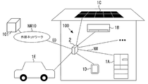
- FIG. 1 is a system configuration diagram showing Embodiment 1 of the power management system of the present invention.
- the power management system 100 will be described with reference to FIG.
- the power management system 100 of FIG. 1 manages the power of a plurality of electrical devices 1A to 1C installed in a house, for example (HEMS: HOME ENERGY MANAGEMENT SYSTEM).
- HEMS HOME ENERGY MANAGEMENT SYSTEM
- a plurality of electrical devices 1A to 1C are connected to the centralized controller 2 via a wired or wireless network NW.
- the centralized controller 2 is connected to the external network NW10, and can acquire power supply information ED indicating the power supply status from the power company 101, for example.
- examples of the plurality of electric devices connected to the centralized controller 2 include a refrigerator 1A, an air conditioner 1B, and an installation type or tablet type information terminal device (interface device) 1C.
- the centralized controller 2 is also connected to an installation type or tablet type information terminal device 1C, and the user can use the information terminal device 1C to check the power usage status and operate each device. It is like that.
- the electric devices 1A to 1C connected to the centralized controller 2 are not limited to the above types, and for example, devices such as a water heater, lighting, and television may be connected.
- the power management system 100 is linked to the electric vehicle EV and the solar power generation panel PV, and the electric power generated in the solar power generation panel PV is supplied to the plurality of electric devices 1A to 1C.
- the EV battery is charged.
- the power stored in the storage battery of the electric vehicle EV is supplied to the plurality of electric devices 1A to 1C.
- the centralized controller 2 has a function of adjusting the power load in the home according to the power generation / charging status of the photovoltaic power generation panel PV and the electric vehicle EV.
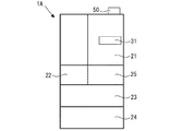
- FIG. 2 is a schematic front view showing the first embodiment of the refrigerator of the present invention
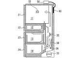
- FIG. 3 is a schematic sectional view showing the first embodiment of the refrigerator of the present invention
- the refrigerator 1A has a refrigerating room 11 provided at the uppermost stage and a plurality of storage rooms 12 to 15 provided at the lower stage of the refrigerating room 11.
- a door 21 is disposed in front of the refrigerator compartment 11, and doors 22 to 25 are disposed in front of the storage compartments 12-15.
- the door 21 of the refrigerating room 11 is provided with an operation panel 31 operated by the user. The user operates the operation panel 31 to adjust the set temperature of the refrigerating room 11 and the storage rooms 12 to 15 or to quickly cool the room.
- Each of the refrigerating room 11 and each of the storage rooms 12 to 15 is provided with a door switch (not shown) that detects opening and closing of the door, and when it is detected that the door 21 of the refrigerating room 11 is opened, the refrigerating room 11 The interior lighting 32 in the room 11 is turned on.
- the refrigerator 1A has a refrigeration cycle circuit for cooling and circulating air, and includes a compressor 33, a cooler 34, and a blower fan 35.
- the compressor 33 compresses the refrigerant sent to the cooler 34
- the cooler 34 cools the air in the warehouse by exchanging heat between the refrigerant compressed by the compressor 33 and the air.
- the blower fan 35 circulates the air cooled by the cooler 34 from the air passage to the refrigerator compartment 11 and the storage compartments 12 to 15.
- a damper (not shown) that can be opened and closed is provided in the air passage, and the temperature of each room is adjusted by opening and closing the damper according to the temperature detected by an indoor temperature sensor (not shown) provided in each room.
- a heater 36 for melting frost attached to the cooler 34 is attached to the lower part of the cooler 34, and the melted moisture is not directly applied to the heater 36, so that it is not between the cooler 34 and the heater 36.
- a cover is installed.
- the refrigerator 1A includes a control unit 40 for controlling the operation of the refrigerator 1A provided on the back side, and an information transmission unit 50 for the control unit 40 to transmit and receive data to and from the outside.
- the control part 40 is comprised from microcontrollers, such as DSP, for example, and each actuator and each sensor in a store
- the information transmission unit 50 includes, for example, a communication adapter, and transmits / receives various data between the centralized controller 2 and the control unit 40 via the information transmission unit 50.
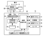
- FIG. 4 is a functional block diagram showing an example of the centralized controller 2 and the control unit 40 of the refrigerator 1A.
- the centralized controller 2 and the control unit 40 of the refrigerator 1A will be described with reference to FIGS.
- the centralized controller 2 includes a difficulty level determination unit 3 and a difficulty level determination table 4.
- the difficulty level determination means 3 determines a power supply difficulty level SD that indicates the degree of difficulty of power supply to the plurality of electrical devices 1A to 1C. Specifically, the difficulty level determination means 3 determines the power supply difficulty level SD based on the power supply information ED, the power usage status EU, and the power generation status in the photovoltaic power generation panel PV.
- the difficulty level determination means 3 acquires power supply information ED transmitted from the power company 101 or the like via the external network NW10 (see FIG. 1). Further, the difficulty level determination means 3 acquires the power usage status EU from each of the electric devices 1A to 1C, and acquires the power generation status from the solar power generation panel PV. Then, the centralized controller 2 determines the power supply difficulty level SD using the difficulty level determination table 4 from the power supply information ED acquired from the external network NW10 and the power usage statuses of the electrical devices 1A to 1C.
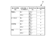
- FIG. 5 is a schematic diagram showing an example of the difficulty level determination table 4 of FIG.
- the power supply difficulty level SD in FIG. 5 is set in stages from “0” to “8”, and indicates that power supply becomes more difficult as the number increases.
- the difficulty level determination table 4 stores the power supply difficulty level SD in association with the power supply information ED, the power usage status EU, and the power generation status. For example, when the power supply information ED is classified as “no problem”, the power generation of the photovoltaic power generation panel PV is classified as “high”, and the power usage status EU is classified as “low”, the power supply difficulty level SD is the power “0” is set so that there is no problem in supply.
- the power supply information ED is classified as “power failure”
- the power generation status of the photovoltaic power generation panel PV is classified as “low”
- the power usage status EU is classified as “high”
- the power supply difficulty level SD is It is set to “8” where power supply is tight.
- the power usage status EU and the power generation status are classified by threshold processing, for example.
- the power supply difficulty level SD “0” to “8” is set according to the three conditions of the power supply information ED, the power generation status, and the power usage status EU, but one of the three is set. It may be set from the above conditions, or may be set by adding other conditions (such as the charging status of the electric vehicle EV). Further, although the power supply difficulty level SD is classified into nine levels from “0” to “8”, it is only necessary to be able to distinguish between normal use and emergency, and it may be two or more levels.
- the control unit 40 of the refrigerator 1A of FIG. 4 has a function of selecting and executing the power suppression control according to the power supply difficulty level SD determined by the centralized controller 2.
- the control unit 40 includes a suppression control setting unit 41, a control setting table 42, and a device control unit 43.
- the suppression control setting unit 41 sets the power suppression control A to H to be executed from the control setting table 42 using the power supply difficulty level SD determined by the difficulty level determination unit 3.
- the control setting table 42 is set with priorities of a plurality of power suppression controls A to H according to the power supply difficulty level SD, and the suppression control setting means 41 corresponds to the power supply difficulty level SD.
- the priority order of the plurality of power suppression controls A to H is set.
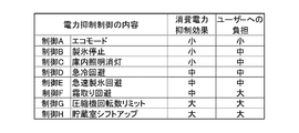
- FIG. 6 is a table showing the ratio between the effect of suppressing power consumption and the burden placed on the user in each power suppression control A to H
- FIG. 7 is a schematic diagram showing an example of the data structure of the control setting table 42.
- the control setting table 42 is set with power suppression controls A to H that suppress the use of power of the refrigerator 1A, and defines the order in which the power suppression controls A to H are performed. Are stored in association with the power supply difficulty level SD.
- the control contents of each power suppression control A to H will be described.
- Power suppression control A Eco mode judges the usage status of the refrigerator from the door open / close sensor and temperature sensor, and if the usage frequency is low, raise the set temperature of the storage room slightly (about 2K) Thus, it is power suppression control that suppresses unnecessary cooling and reduces power consumption. Although it is a control to raise the temperature of the storage chambers 12 to 15, the temperature is raised in a range that does not affect food preservation at a timing of infrequent use according to the usage status of the refrigerator, so there is almost no burden on the user. .
- Ice making stop is a power suppression control that stops the function of automatically making ice and suppresses the cold air (capability) necessary to make ice. Since ice cannot be made automatically, it imposes a burden on the user who wants to use ice. However, in a scene where ice is not used, such as in winter, the control has little burden on the user.
- In-compartment illumination off is a power suppression control that does not turn on the interior illumination 32 even when the door 21 of the refrigerator compartment 11 is detected to be opened. Even if the door 21 of the refrigerating room 11 is opened, the visibility in the refrigerating room 11 is lowered by the fact that the interior lighting 32 is not turned on. Therefore, there is no influence on storage / cooling of food, but a burden is imposed on the user. It is.
- the rapid cooling avoidance is a power suppression control that prevents the rapid cooling function that can be set on the operation panel 31 from being set.
- the rapid cooling function is started, it is possible to rapidly cool the temperature of the storage chamber by increasing the rotation speed of the compressor 33 and lowering the set temperature of the storage chamber.
- power consumption increases, it is possible to prevent an increase in power consumption by preventing the rapid cooling function from being set.
- Rapid ice making avoidance is a power suppression control that prevents the quick ice making function that can be set on the operation panel 31 from being set.
- Rapid ice making is started, it is possible to shorten the time during which ice can be formed by increasing the number of revolutions of the compressor 33 and lowering the set temperature of the storage chamber 12 (ice making chamber).
- the increase in power consumption can be prevented by preventing rapid ice making.
- the rapid cooling function and the rapid ice making function described above are additional merit functions set on the operation panel 31.
- the power suppression control D and the power suppression control E are performed. But there is almost no burden. However, this control is burdensome for users who use rapid cooling and ice making on a daily basis.
- the defrosting avoidance function is a power suppression control that does not energize a heater (not shown) for melting frost adhering to the cooler 34. If a large amount of frost adheres to the cooler 34, the cooling capacity is lowered. Therefore, the frost in the cooler 34 is usually melted by heating the heater once every one to two days. However, since the extra power of energizing the heater is consumed, the cooling performance is reduced by not energizing the heater or extending the heater energization timing once every 3 to 4 days. However, an increase in power consumption can be prevented.
- the compressor rotation speed limit function is a power suppression control that prohibits rotation at a high-speed rotation stage among the rotation speeds of the compressor 33 having a plurality of stages.
- the rotation speed of the compressor 33 is increased to increase the cooling capacity.
- the upper limit of the number of revolutions may be distinguished by the power supply difficulty level. For example, when the power supply difficulty level is low, the upper limit is the eighth stage among the 10 speed stages, and when the power supply difficulty level is high, 10 is set. It is good also considering the 6th stage among a stage as an upper limit.
- the power suppression controls F and G are controls that reduce the cooling capacity. Even if you want to cool the storage room, there is a possibility that it will not be able to cool to the target set temperature due to insufficient cooling capacity, so the storage period of food will be shortened, and in the worst case the frozen food will melt It puts a big burden on the user.
- Power suppression control H storage room temperature control
- Storage room temperature shift-up is a power suppression control in which the set temperature of each storage room 12-15 is higher than the normal temperature.
- the power suppression control H is a control that raises the set temperature of the storage chambers 12 to 15 above the normal temperature, so that the burden on the user such as shortening the storage period of the food and melting the frozen food is reduced. It is very big control. Usually, it operates at a set temperature according to the food stored in each room, such as a freezer room: about -18 ° C, a refrigerated room: about 3 ° C. Therefore, power consumption can be suppressed.
- the amount of increase in the set temperature may be made variable according to the power supply difficulty level SD.
- the freezer compartment when the power supply difficulty level is low, the freezer compartment is about ⁇ 15 ° C., and when the power supply difficulty level SD is high, the freezer compartment: It may be distinguished from about -12 ° C.
- the temperature of the storage rooms 12 and 13 ice making room, freezing room, etc.
- the freezer compartment when the power supply is really tight, usually the temperature of the storage rooms 12 and 13 (ice making room, freezing room, etc.) for storing food in a frozen state is set to a refrigeration temperature zone (0 ° C. or higher).
- the food cannot be stored frozen, but the food can be stored for a long time without rot.
- the storage room where the temperature shift up is performed may be distinguished according to the power supply difficulty level SD. For example, when the power supply is low, only the refrigerating room 11 is performed and when the power supply difficulty level SD is high, You may make it implement in the storage rooms 12-15.
- the control with a smaller power consumption suppression effect has a smaller burden on the user, and the greater the power consumption suppression effect, the greater the burden on the user.
- the priority order is set so that the degree of suppression of power consumption is reduced to reduce the burden on the user.
- priority is set so as to increase the effect of suppressing power consumption.
- the device control means 43 has a function of detecting the power usage status EU in the entire refrigerator 1A and outputting it to the information transmission means 50.
- the information transmission means 50 transmits the power usage status to the centralized controller 2 via the network NW, and the centralized controller 2 receives the power usage status EU sent from the refrigerator 1A and other electrical devices such as the air conditioner 1B and the information terminal device 1C. Based on the transmitted power usage status EU, the above-described power supply difficulty level SD is determined (see FIG. 5).
- control unit 40 and the information transmission unit 50 are individually provided. However, as illustrated in FIG. 8, the information transmission unit 50 may be provided in the control unit 40.
- the control unit 40 and the information transmission unit 50 are separately provided as shown in FIG. 4, the control unit 40 is manufactured at low cost by providing the information transmission unit 50 only to the user who uses the power management system 100. Can do.
- the information transmission means 50 is configured by providing a communication circuit in the control unit 40 as shown in FIG. 8, the unit price of the control unit 40 increases, but there is no need to attach another component outside the refrigerator 1A.
- the power management system 100 can be used.
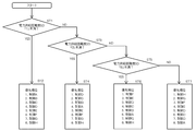
- FIG. 9 is a flowchart showing an operation example of the power management system 100 and the refrigerator 1A of FIG. 4, and an operation example of the power management system 100 and the refrigerator 1A will be described with reference to FIGS.
- the power supply difficulty level SD is calculated every predetermined period.
- the power supply difficulty level SD is transmitted from the centralized controller 2 to the refrigerator 1A via the network NW.
- the priority order of the power suppression controls A to H is set in the suppression control setting unit 41 of the control unit 40 in accordance with the power supply difficulty level SD.
- step ST1 when the power supply difficulty level SD is less than “1” (step ST1), the priority of each power suppression control for suppressing power consumption is set to high: A ⁇ B ⁇ C ⁇ D ⁇ E ⁇ F. ⁇ G ⁇ H: Set to low (step ST2).
- step ST3 When the power supply difficulty level SD is not less than “1” and less than “3” (step ST3), the priority is set to high: D ⁇ C ⁇ B ⁇ A ⁇ E ⁇ F ⁇ G ⁇ H: low ( Step ST4).
- step ST5 When the power supply difficulty is “3” or more and less than “5” (step ST5), the priority is set in the order of high: F ⁇ E ⁇ D ⁇ C ⁇ B ⁇ A ⁇ G ⁇ H: low (step ST6).
- step ST7 When the power supply difficulty level SD is “5” or more, the priority is set to high: H ⁇ G ⁇ F ⁇ E ⁇ D ⁇ C ⁇ B ⁇ A: low (step ST7).
- FIG. 9 illustrates the case where the determination is made in the order of the power supply difficulty level SD, the order is not limited as long as the priority order corresponding to the power supply difficulty level SD is set.
- the priority order of the power suppression controls A to H that suppress power consumption in the refrigerator 1A according to the power supply difficulty level SD when the power supply difficulty level SD is low, the power consumption suppression level is reduced.
- the refrigerator 1A can be operated in accordance with the power supply status without stopping the cooling.
- the power supply difficulty level SD is transmitted from the centralized controller 2 to the refrigerator 1A by the operation of the user's information terminal device 1C, control that places a burden without the user's knowledge is not automatically performed. Even if information indicating that power supply is difficult is transmitted on the external network NW10, it is possible to select whether or not to implement according to the power situation for each user.
- FIG. FIG. 10 is a functional block diagram showing Embodiment 2 of the power management system and the refrigerator of the present invention, and the control unit 140 will be described with reference to FIG.
- the control unit 140 of FIG. 10 parts having the same configuration as the control unit 40 of FIG. 10 illustrates the case where the control unit 40 and the information transmission unit 50 are provided separately, the information transmission unit 50 may be provided in the control unit 40 (FIG. 8). reference).
- the control unit 140 in FIG. 10 is different from the control unit 40 in FIG. 4 in that the suppression control setting unit 141 sets feasible control that can be performed using the power supply difficulty level SD and the control setting table 142. is there.
- the suppression control setting unit 141 sets an executable control among the plurality of power suppression controls A to H using the power supply difficulty level SD and the control setting table 142.
- the device control unit 43 Implements the power suppression control set in the suppression control setting means 41.
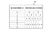
- FIG. 11 is a schematic diagram showing an example of the control setting table 142 of FIG.
- the contents of feasible control among the plurality of power suppression controls A to H are set for each power supply difficulty level SD.
- the control setting table 142 is set so that the power suppression control A to H that can be performed increases as the power supply difficulty level SD increases.
- FIG. 12 is a flowchart showing an operation example of the refrigerator 1A of FIG. 10, and an operation example of the refrigerator 1A will be described with reference to FIGS.
- the power suppression control that can be performed is “power suppression control A, B” (step ST11).
- the power suppression control that can be performed is set to “power suppression control A, B, C, D” (step ST12).
- the power suppression control that can be performed is “power suppression control A, B, C, D, E, F” (step ST13).
- the power supply difficulty level SD is “5” or more, all the power suppression controls A to H can be performed (step ST14).
- the implementation suppression control is illustrated as the case where the power supply difficulty level SD is classified into three, “1”, “3”, and “5”. It is also possible to distinguish between the power supply difficulty levels SD.
- the power suppression control that can be performed when the power supply difficulty level SD is not limited to that illustrated in FIG. 11, for example, even if the power supply difficulty level SD is less than “1”.
- the suppression control may be “power suppression control A, B, C, D, E”, and the control that can be performed may be determined based on the balance of the power supply difficulty level SD, the power suppression effect, and the burden on the user.
Landscapes
- Engineering & Computer Science (AREA)
- Physics & Mathematics (AREA)
- Power Engineering (AREA)
- General Physics & Mathematics (AREA)
- Automation & Control Theory (AREA)
- General Engineering & Computer Science (AREA)
- Electromagnetism (AREA)
- Radar, Positioning & Navigation (AREA)
- Combustion & Propulsion (AREA)
- Mechanical Engineering (AREA)
- Thermal Sciences (AREA)
- Chemical & Material Sciences (AREA)
- Devices That Are Associated With Refrigeration Equipment (AREA)
- Remote Monitoring And Control Of Power-Distribution Networks (AREA)
- Supply And Distribution Of Alternating Current (AREA)
- Management, Administration, Business Operations System, And Electronic Commerce (AREA)
Priority Applications (4)
| Application Number | Priority Date | Filing Date | Title |
|---|---|---|---|
| SG11201505642RA SG11201505642RA (en) | 2013-03-26 | 2014-02-04 | Power management system and refrigerator |
| EP14776348.6A EP2980947B1 (en) | 2013-03-26 | 2014-02-04 | Power management system and refrigerator |
| CN201480018137.8A CN105122570B (zh) | 2013-03-26 | 2014-02-04 | 电力管理系统以及电冰箱 |
| US14/762,495 US10031543B2 (en) | 2013-03-26 | 2014-02-04 | Power management system and refrigerator |
Applications Claiming Priority (2)
| Application Number | Priority Date | Filing Date | Title |
|---|---|---|---|
| JP2013063938A JP6124642B2 (ja) | 2013-03-26 | 2013-03-26 | 電力管理システム及び冷蔵庫 |
| JP2013-063938 | 2013-03-26 |
Publications (1)
| Publication Number | Publication Date |
|---|---|
| WO2014156312A1 true WO2014156312A1 (ja) | 2014-10-02 |
Family
ID=51623313
Family Applications (1)
| Application Number | Title | Priority Date | Filing Date |
|---|---|---|---|
| PCT/JP2014/052588 Ceased WO2014156312A1 (ja) | 2013-03-26 | 2014-02-04 | 電力管理システム及び冷蔵庫 |
Country Status (6)
| Country | Link |
|---|---|
| US (1) | US10031543B2 (enExample) |
| EP (1) | EP2980947B1 (enExample) |
| JP (1) | JP6124642B2 (enExample) |
| CN (1) | CN105122570B (enExample) |
| SG (1) | SG11201505642RA (enExample) |
| WO (1) | WO2014156312A1 (enExample) |
Families Citing this family (6)
| Publication number | Priority date | Publication date | Assignee | Title |
|---|---|---|---|---|
| JP6125009B2 (ja) * | 2013-06-21 | 2017-05-10 | 三菱電機株式会社 | 電力管理システム及び冷蔵庫 |
| JP6410550B2 (ja) * | 2014-10-15 | 2018-10-24 | 三菱電機株式会社 | 冷蔵庫及びそれを備えたネットワークシステム |
| DE102014221318A1 (de) * | 2014-10-21 | 2016-04-21 | BSH Hausgeräte GmbH | Haushaltskältegerät mit Eisbereiter |
| JP6567034B2 (ja) * | 2017-12-27 | 2019-08-28 | 三菱電機株式会社 | 連携システム及び集中コントローラ |
| US11125493B2 (en) * | 2018-03-07 | 2021-09-21 | Carrier Corporation | Method and system for controlling use of a portable cooling container |
| JP7048446B2 (ja) * | 2018-07-31 | 2022-04-05 | 日立グローバルライフソリューションズ株式会社 | 制御ソフトウエアを書き換え可能な冷蔵庫 |
Citations (5)
| Publication number | Priority date | Publication date | Assignee | Title |
|---|---|---|---|---|
| JPH07305935A (ja) * | 1994-05-12 | 1995-11-21 | Sanyo Electric Co Ltd | ショーケースなどの運転制御装置 |
| JPH11296771A (ja) | 1998-04-13 | 1999-10-29 | Matsushita Electric Works Ltd | 消費電力監視機能を備えた住宅監視システム |
| WO2006126495A1 (ja) * | 2005-05-24 | 2006-11-30 | Daikin Industries, Ltd. | 空調システム |
| JP2009278796A (ja) * | 2008-05-15 | 2009-11-26 | Tempearl Ind Co Ltd | 住宅用分電盤 |
| JP2010193705A (ja) * | 2009-02-18 | 2010-09-02 | General Electric Co <Ge> | エネルギ管理 |
Family Cites Families (10)
| Publication number | Priority date | Publication date | Assignee | Title |
|---|---|---|---|---|
| CN2417439Y (zh) * | 2000-02-18 | 2001-01-31 | 李健 | 电冰箱智能节电保护器 |
| ES2311360B1 (es) * | 2006-07-07 | 2009-12-02 | Bsh Electrodomesticos España, S.A. | Aparato electrodomestico. |
| JP4931656B2 (ja) * | 2007-03-19 | 2012-05-16 | 三洋電機株式会社 | 冷熱機器制御装置及び冷却機器の制御方法 |
| JP4551457B2 (ja) * | 2008-01-30 | 2010-09-29 | 日東工器株式会社 | 固定装置付き回転切削装置 |
| US20100217451A1 (en) * | 2009-02-24 | 2010-08-26 | Tetsuya Kouda | Energy usage control system and method |
| ES2585089T3 (es) * | 2009-03-27 | 2016-10-03 | Mitsubishi Electric Corporation | Aparato de atomización electrostática, dispositivo, acondicionador de aire y refrigerador |
| KR101637354B1 (ko) * | 2010-01-20 | 2016-07-07 | 엘지전자 주식회사 | 냉장고 및 그 제어방법 |
| CN102192625B (zh) * | 2010-03-10 | 2014-05-07 | 株式会社东芝 | 冰箱 |
| US8869546B2 (en) | 2010-11-03 | 2014-10-28 | General Electric Company | Refrigeration demand response recovery |
| KR20130014080A (ko) | 2011-07-29 | 2013-02-07 | 삼성전자주식회사 | 냉장고 및 그 제어 방법 |
-
2013
- 2013-03-26 JP JP2013063938A patent/JP6124642B2/ja active Active
-
2014
- 2014-02-04 EP EP14776348.6A patent/EP2980947B1/en not_active Not-in-force
- 2014-02-04 US US14/762,495 patent/US10031543B2/en active Active
- 2014-02-04 SG SG11201505642RA patent/SG11201505642RA/en unknown
- 2014-02-04 WO PCT/JP2014/052588 patent/WO2014156312A1/ja not_active Ceased
- 2014-02-04 CN CN201480018137.8A patent/CN105122570B/zh active Active
Patent Citations (5)
| Publication number | Priority date | Publication date | Assignee | Title |
|---|---|---|---|---|
| JPH07305935A (ja) * | 1994-05-12 | 1995-11-21 | Sanyo Electric Co Ltd | ショーケースなどの運転制御装置 |
| JPH11296771A (ja) | 1998-04-13 | 1999-10-29 | Matsushita Electric Works Ltd | 消費電力監視機能を備えた住宅監視システム |
| WO2006126495A1 (ja) * | 2005-05-24 | 2006-11-30 | Daikin Industries, Ltd. | 空調システム |
| JP2009278796A (ja) * | 2008-05-15 | 2009-11-26 | Tempearl Ind Co Ltd | 住宅用分電盤 |
| JP2010193705A (ja) * | 2009-02-18 | 2010-09-02 | General Electric Co <Ge> | エネルギ管理 |
Also Published As
| Publication number | Publication date |
|---|---|
| CN105122570A (zh) | 2015-12-02 |
| EP2980947B1 (en) | 2018-12-19 |
| US20150355657A1 (en) | 2015-12-10 |
| US10031543B2 (en) | 2018-07-24 |
| JP6124642B2 (ja) | 2017-05-10 |
| CN105122570B (zh) | 2017-12-08 |
| JP2014192937A (ja) | 2014-10-06 |
| EP2980947A1 (en) | 2016-02-03 |
| SG11201505642RA (en) | 2015-09-29 |
| EP2980947A4 (en) | 2016-11-23 |
Similar Documents
| Publication | Publication Date | Title |
|---|---|---|
| JP6124642B2 (ja) | 電力管理システム及び冷蔵庫 | |
| KR101084418B1 (ko) | 냉장고 | |
| JP6125009B2 (ja) | 電力管理システム及び冷蔵庫 | |
| CN101929779B (zh) | 冰箱 | |
| CN105737510B (zh) | 冷柜的控制方法、系统及具有其的冷柜 | |
| JP2017015344A (ja) | 冷蔵庫 | |
| US8291718B2 (en) | DSM defrost during high demand | |
| CN106524647A (zh) | 一种冰箱及其控制方法 | |
| JP6567034B2 (ja) | 連携システム及び集中コントローラ | |
| TWI604161B (zh) | Cooperative system and centralized controller and centralized control method | |
| JP2010071480A (ja) | 冷蔵庫 | |
| JP2011002142A (ja) | 冷蔵庫 | |
| JP2014224622A (ja) | 冷蔵庫 | |
| JP2014077618A (ja) | 冷凍冷蔵庫 | |
| JP2003056962A (ja) | 冷蔵庫 | |
| CA2753806C (en) | Dsm defrost during high demand | |
| JP2022140721A (ja) | 冷蔵庫、冷蔵庫制御方法、及び、冷蔵庫制御プログラム | |
| WO2016046991A1 (ja) | 空調冷凍複合設備 | |
| JP6837423B2 (ja) | 冷蔵庫 | |
| JP2013064561A (ja) | 冷蔵庫 | |
| EP2636976B1 (en) | Hybrid refrigerator and control method thereof | |
| JP2005156104A (ja) | 冷蔵庫 | |
| CN118670084A (zh) | 一种冰箱及其控制方法 | |
| JP2005156103A (ja) | 冷蔵庫 |
Legal Events
| Date | Code | Title | Description |
|---|---|---|---|
| 121 | Ep: the epo has been informed by wipo that ep was designated in this application |
Ref document number: 14776348 Country of ref document: EP Kind code of ref document: A1 |
|
| WWE | Wipo information: entry into national phase |
Ref document number: 14762495 Country of ref document: US |
|
| NENP | Non-entry into the national phase |
Ref country code: DE |
|
| WWE | Wipo information: entry into national phase |
Ref document number: 2014776348 Country of ref document: EP |