WO2014156264A1 - 電池システム - Google Patents
電池システム Download PDFInfo
- Publication number
- WO2014156264A1 WO2014156264A1 PCT/JP2014/051613 JP2014051613W WO2014156264A1 WO 2014156264 A1 WO2014156264 A1 WO 2014156264A1 JP 2014051613 W JP2014051613 W JP 2014051613W WO 2014156264 A1 WO2014156264 A1 WO 2014156264A1
- Authority
- WO
- WIPO (PCT)
- Prior art keywords
- battery
- controller
- cell
- state
- cell group
- Prior art date
Links
Images

Classifications
-
- H—ELECTRICITY
- H01—ELECTRIC ELEMENTS
- H01M—PROCESSES OR MEANS, e.g. BATTERIES, FOR THE DIRECT CONVERSION OF CHEMICAL ENERGY INTO ELECTRICAL ENERGY
- H01M10/00—Secondary cells; Manufacture thereof
- H01M10/42—Methods or arrangements for servicing or maintenance of secondary cells or secondary half-cells
- H01M10/425—Structural combination with electronic components, e.g. electronic circuits integrated to the outside of the casing
-
- G—PHYSICS
- G01—MEASURING; TESTING
- G01R—MEASURING ELECTRIC VARIABLES; MEASURING MAGNETIC VARIABLES
- G01R31/00—Arrangements for testing electric properties; Arrangements for locating electric faults; Arrangements for electrical testing characterised by what is being tested not provided for elsewhere
- G01R31/36—Arrangements for testing, measuring or monitoring the electrical condition of accumulators or electric batteries, e.g. capacity or state of charge [SoC]
- G01R31/371—Arrangements for testing, measuring or monitoring the electrical condition of accumulators or electric batteries, e.g. capacity or state of charge [SoC] with remote indication, e.g. on external chargers
-
- G—PHYSICS
- G01—MEASURING; TESTING
- G01R—MEASURING ELECTRIC VARIABLES; MEASURING MAGNETIC VARIABLES
- G01R31/00—Arrangements for testing electric properties; Arrangements for locating electric faults; Arrangements for electrical testing characterised by what is being tested not provided for elsewhere
- G01R31/36—Arrangements for testing, measuring or monitoring the electrical condition of accumulators or electric batteries, e.g. capacity or state of charge [SoC]
- G01R31/396—Acquisition or processing of data for testing or for monitoring individual cells or groups of cells within a battery
-
- H—ELECTRICITY
- H01—ELECTRIC ELEMENTS
- H01M—PROCESSES OR MEANS, e.g. BATTERIES, FOR THE DIRECT CONVERSION OF CHEMICAL ENERGY INTO ELECTRICAL ENERGY
- H01M10/00—Secondary cells; Manufacture thereof
- H01M10/42—Methods or arrangements for servicing or maintenance of secondary cells or secondary half-cells
- H01M10/4207—Methods or arrangements for servicing or maintenance of secondary cells or secondary half-cells for several batteries or cells simultaneously or sequentially
-
- H—ELECTRICITY
- H01—ELECTRIC ELEMENTS
- H01M—PROCESSES OR MEANS, e.g. BATTERIES, FOR THE DIRECT CONVERSION OF CHEMICAL ENERGY INTO ELECTRICAL ENERGY
- H01M10/00—Secondary cells; Manufacture thereof
- H01M10/42—Methods or arrangements for servicing or maintenance of secondary cells or secondary half-cells
- H01M10/48—Accumulators combined with arrangements for measuring, testing or indicating the condition of cells, e.g. the level or density of the electrolyte
- H01M10/482—Accumulators combined with arrangements for measuring, testing or indicating the condition of cells, e.g. the level or density of the electrolyte for several batteries or cells simultaneously or sequentially
-
- H—ELECTRICITY
- H04—ELECTRIC COMMUNICATION TECHNIQUE
- H04B—TRANSMISSION
- H04B7/00—Radio transmission systems, i.e. using radiation field
- H04B7/24—Radio transmission systems, i.e. using radiation field for communication between two or more posts
-
- H—ELECTRICITY
- H04—ELECTRIC COMMUNICATION TECHNIQUE
- H04Q—SELECTING
- H04Q9/00—Arrangements in telecontrol or telemetry systems for selectively calling a substation from a main station, in which substation desired apparatus is selected for applying a control signal thereto or for obtaining measured values therefrom
-
- H—ELECTRICITY
- H01—ELECTRIC ELEMENTS
- H01M—PROCESSES OR MEANS, e.g. BATTERIES, FOR THE DIRECT CONVERSION OF CHEMICAL ENERGY INTO ELECTRICAL ENERGY
- H01M10/00—Secondary cells; Manufacture thereof
- H01M10/05—Accumulators with non-aqueous electrolyte
- H01M10/052—Li-accumulators
- H01M10/0525—Rocking-chair batteries, i.e. batteries with lithium insertion or intercalation in both electrodes; Lithium-ion batteries
-
- H—ELECTRICITY
- H01—ELECTRIC ELEMENTS
- H01M—PROCESSES OR MEANS, e.g. BATTERIES, FOR THE DIRECT CONVERSION OF CHEMICAL ENERGY INTO ELECTRICAL ENERGY
- H01M10/00—Secondary cells; Manufacture thereof
- H01M10/42—Methods or arrangements for servicing or maintenance of secondary cells or secondary half-cells
- H01M10/425—Structural combination with electronic components, e.g. electronic circuits integrated to the outside of the casing
- H01M2010/4271—Battery management systems including electronic circuits, e.g. control of current or voltage to keep battery in healthy state, cell balancing
-
- H—ELECTRICITY
- H01—ELECTRIC ELEMENTS
- H01M—PROCESSES OR MEANS, e.g. BATTERIES, FOR THE DIRECT CONVERSION OF CHEMICAL ENERGY INTO ELECTRICAL ENERGY
- H01M10/00—Secondary cells; Manufacture thereof
- H01M10/42—Methods or arrangements for servicing or maintenance of secondary cells or secondary half-cells
- H01M10/425—Structural combination with electronic components, e.g. electronic circuits integrated to the outside of the casing
- H01M2010/4278—Systems for data transfer from batteries, e.g. transfer of battery parameters to a controller, data transferred between battery controller and main controller
-
- H—ELECTRICITY
- H01—ELECTRIC ELEMENTS
- H01M—PROCESSES OR MEANS, e.g. BATTERIES, FOR THE DIRECT CONVERSION OF CHEMICAL ENERGY INTO ELECTRICAL ENERGY
- H01M2220/00—Batteries for particular applications
- H01M2220/20—Batteries in motive systems, e.g. vehicle, ship, plane
-
- H—ELECTRICITY
- H02—GENERATION; CONVERSION OR DISTRIBUTION OF ELECTRIC POWER
- H02J—CIRCUIT ARRANGEMENTS OR SYSTEMS FOR SUPPLYING OR DISTRIBUTING ELECTRIC POWER; SYSTEMS FOR STORING ELECTRIC ENERGY
- H02J7/00—Circuit arrangements for charging or depolarising batteries or for supplying loads from batteries
-
- H—ELECTRICITY
- H04—ELECTRIC COMMUNICATION TECHNIQUE
- H04Q—SELECTING
- H04Q2209/00—Arrangements in telecontrol or telemetry systems
- H04Q2209/40—Arrangements in telecontrol or telemetry systems using a wireless architecture
-
- H—ELECTRICITY
- H04—ELECTRIC COMMUNICATION TECHNIQUE
- H04Q—SELECTING
- H04Q2209/00—Arrangements in telecontrol or telemetry systems
- H04Q2209/40—Arrangements in telecontrol or telemetry systems using a wireless architecture
- H04Q2209/47—Arrangements in telecontrol or telemetry systems using a wireless architecture using RFID associated with sensors
-
- H—ELECTRICITY
- H04—ELECTRIC COMMUNICATION TECHNIQUE
- H04Q—SELECTING
- H04Q2209/00—Arrangements in telecontrol or telemetry systems
- H04Q2209/80—Arrangements in the sub-station, i.e. sensing device
- H04Q2209/82—Arrangements in the sub-station, i.e. sensing device where the sensing device takes the initiative of sending data
- H04Q2209/826—Arrangements in the sub-station, i.e. sensing device where the sensing device takes the initiative of sending data where the data is sent periodically
-
- H—ELECTRICITY
- H04—ELECTRIC COMMUNICATION TECHNIQUE
- H04Q—SELECTING
- H04Q2209/00—Arrangements in telecontrol or telemetry systems
- H04Q2209/80—Arrangements in the sub-station, i.e. sensing device
- H04Q2209/88—Providing power supply at the sub-station
-
- Y—GENERAL TAGGING OF NEW TECHNOLOGICAL DEVELOPMENTS; GENERAL TAGGING OF CROSS-SECTIONAL TECHNOLOGIES SPANNING OVER SEVERAL SECTIONS OF THE IPC; TECHNICAL SUBJECTS COVERED BY FORMER USPC CROSS-REFERENCE ART COLLECTIONS [XRACs] AND DIGESTS
- Y02—TECHNOLOGIES OR APPLICATIONS FOR MITIGATION OR ADAPTATION AGAINST CLIMATE CHANGE
- Y02E—REDUCTION OF GREENHOUSE GAS [GHG] EMISSIONS, RELATED TO ENERGY GENERATION, TRANSMISSION OR DISTRIBUTION
- Y02E60/00—Enabling technologies; Technologies with a potential or indirect contribution to GHG emissions mitigation
- Y02E60/10—Energy storage using batteries
Definitions
- the present invention relates to a battery system.
- the storage battery module constituting this is generally configured by connecting a plurality of battery cells in series and parallel.
- Lithium ion batteries are widely known as large capacity secondary batteries. In handling lithium ion batteries, measures such as prevention of high voltage charging and deterioration of performance due to overdischarge are required. For this reason, a storage battery module that is mounted on a hybrid electric vehicle or an electric vehicle and that uses a lithium ion battery for each battery cell generally has a function of monitoring the battery state such as voltage, current, and temperature for each battery cell. ing.
- a state monitoring device disclosed in Patent Document 1 below is known.
- an electromagnetic induction type wireless tag is provided in a module for measuring the voltage value of each battery cell, and the voltage value of each battery cell is transmitted to a reader by a wireless signal using the wireless tag. This reduces the cost required for wiring and insulation.
- the electromagnetic induction type wireless tag used in the above-described state monitoring device generally has a short communication distance of about several centimeters to several tens of centimeters. For this reason, the layout between the wireless tag and the reader is less flexible, which may limit the structure of the device.
- a main object of the present invention is to extend the communication distance in a battery system that transmits the state of each battery cell by wireless communication.
- a battery system includes a cell group including a plurality of battery cells or one battery cell, a cell controller provided corresponding to the cell group, and measuring the state of each battery cell in the cell group, and a cell controller A battery controller that wirelessly communicates with each other, and the cell controller wirelessly transmits a state measurement result of each battery cell of the cell group to the battery controller using power supplied from the battery cells of the cell group .
- the communication distance can be extended in a battery system that transmits the state of each battery cell by wireless communication.
- FIG. 1 is a basic configuration diagram of a battery system according to a first embodiment of the present invention. It is explanatory drawing of the wireless transmission method from a battery controller to a cell controller. It is explanatory drawing of the wireless transmission method from a cell controller to a battery controller. It is a basic block diagram of the battery system by the 2nd Embodiment of this invention. It is a basic block diagram of the battery system by the 3rd Embodiment of this invention.
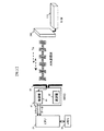
- FIG. 1 is a diagram showing a configuration of an in-vehicle system including a battery system according to an embodiment of the present invention.
- the in-vehicle system shown in FIG. 1 is mounted on a vehicle such as a hybrid electric vehicle or an electric vehicle, and includes a battery system 1, an inverter 2, a motor 3, a relay box 4, and a host controller 300.
- the battery system 1 includes a plurality of cell groups 10 each composed of a plurality of battery cells, and a cell controller 100 is provided corresponding to each cell group 10.
- Each cell controller 100 measures the state (voltage, current, temperature, etc.) of each battery cell in the cell group 10. Then, wireless communication is performed with the battery controller 200 using the power supplied from the battery cells of the cell group 10, and the state measurement result of each battery cell of the cell group 10 is wirelessly transmitted to the battery controller 200. Details of the wireless communication performed at this time will be described later.
- the battery controller 200 acquires the state measurement result of each battery cell of the cell group 10 corresponding to the cell controller 100 from each cell controller 100. Then, based on the obtained state measurement result of each battery cell, the state of charge (SOC: State of Charge) and the deterioration state (SOH: State of Health) of each battery cell are estimated, and the estimation result is sent to the host controller 300. Send.
- SOC State of Charge
- SOH State of Health
- the host controller 300 controls the inverter 2 and the relay box 4 based on the estimation result of the charging state and the deterioration state of each battery cell transmitted from the battery controller 200.
- the inverter 2 converts the DC power supplied from each cell group 10 into three-phase AC power when the relay box 4 is in a conductive state and supplies it to the motor 3 to drive the motor 3 to rotate. Generate power.
- the three-phase AC regenerative power generated by the motor 3 is converted into DC power and output to each cell group 10 to charge the battery cells of each cell group 10.
- the operation of the inverter 2 is controlled by the host controller 300.
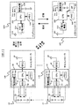
- FIG. 2 is a basic configuration diagram of the battery system according to the first embodiment of the present invention.
- the cell group 10 the cell controller 100, the battery controller 200, and the host controller 300 are shown as basic components among the components of the in-vehicle system shown in FIG.
- the battery controller 200 performs wireless communication with each cell controller 100. Through this wireless communication, the battery controller 200 can request each cell controller 100 for measurement information, cell balancing, and the like of each battery cell in the corresponding cell group 10. In response to the request from the battery controller 200, each cell controller 100 transmits the measurement information of each battery cell of the corresponding cell group 10 to the battery controller 200 or performs cell balancing.
- the host controller 300 performs wireless communication with the battery controller 200. Through this wireless communication, the host controller 300 can request the battery controller 200 to estimate the state of charge or deterioration of each battery cell. In response to the request from the host controller 300, the battery controller 200 estimates the charge state and the deterioration state of each battery cell based on the measurement information of each battery cell of the cell group 10 transmitted from each cell controller 100, The result is transmitted to the host controller 300.
- wireless communication using a so-called semi-passive wireless tag is used as a wireless method having a relatively short communication distance (about several meters).
- so-called low power wireless communication is used as a wireless system having a relatively long communication distance (several hundreds of meters).
- a wireless system such as IEEE802.15.4 can be used.
- Each cell controller 100 includes a plurality of sensors 20, a processing unit 30, an RFID circuit 40, and an antenna 50 provided for each battery cell of the corresponding cell group 10.
- the processing unit 30 includes a power supply circuit 31, an AD converter 32, a CPU 33, and a memory 34.
- Each sensor 20 is a sensor for measuring the state of each battery cell in the cell group 10, and is configured by a voltage sensor, a current sensor, a temperature sensor, and the like. The measurement result of the battery cell state by the sensor 20 is converted into a digital signal by the AD converter 32 and output to the CPU 33 as measurement information.
- the sensor 20 and the AD converter 32 constitute a measurement circuit that measures the state of each battery cell in the cell group 10.
- the power supply circuit 31 receives power supplied from the battery cells of the cell group 10, and generates power supply voltages Vcc and Vdd based on the power.
- the power supply voltage Vcc is used as an operation power supply for the AD converter 32 and the CPU 33
- the power supply voltage Vdd is used as an operation power supply for the RFID circuit 40.
- the power supply circuit 31 can receive power from at least one of the battery cells constituting the cell group 10.
- the CPU 33 executes a process for controlling the operation of the cell controller 100.
- the measurement information of each battery cell output from the AD converter 32 is stored in the memory 34, and the measurement information stored in the memory 34 is wirelessly transmitted to the battery controller 200 in response to a request from the battery controller 200. Send processing for.
- the CPU 33 controls the RFID circuit 40 according to the measurement information read from the memory 34, thereby changing the impedance of the antenna 50 with respect to the radio signal transmitted from the battery controller 200.
- the measurement information according to the state of each battery cell is transmitted to the battery controller 200 as a reflected wave with respect to the radio signal from the battery controller 200. This point will be described in detail later.
- the CPU 33 when a balancing request is transmitted from the battery controller 200, the CPU 33 performs a balancing process for equalizing the charging state of each battery cell of the cell group 10 by controlling a balancing switch (not shown). In addition to this, various processes can be executed by the CPU 33.
- the RFID circuit 40 is a wireless communication circuit for operating the cell controller 100 as a semi-passive wireless tag.
- the radio signal transmitted from the battery controller 200 and received by the antenna 50 is demodulated by the RFID circuit 40 and output to the CPU 33.
- the request content from the battery controller 200 is decoded by the CPU 33, and processing corresponding to the request content is executed in the CPU 33.
- the RFID circuit 40 uses the power supply voltage Vdd to change the impedance of the antenna 50 with respect to the radio signal from the battery controller 200 at a timing according to a predetermined communication rate according to measurement information to be transmitted.
- measurement information corresponding to the state of each battery cell of the cell group 10 is transmitted from the cell controller 100 to the battery controller 200 as a reflected wave of a radio signal transmitted from the battery controller 200.
- the operation of the RFID circuit 40 at this time will be described in detail later.
- the battery controller 200 includes a read / write (R / W) circuit 210, a CPU 220, a power supply circuit 230, a memory 240, and an antenna 250.
- the power supply circuit 230 generates power supply voltages Vcc and Vdd, similar to the power supply circuit 31 of the cell controller 100, based on the power supplied from the battery built in the battery controller 200.
- the battery controller 200 may not use a battery and may use electric power supplied from the outside.
- the CPU 220 controls operations of read / write circuit 210 and memory 240.
- the read / write circuit 210 operates in accordance with the control of the CPU 220 and performs wireless communication with the cell controller 100 and the host controller 300 via the antenna 250.
- the read / write circuit 210 has both a wireless communication function using the above-described semi-passive wireless tag and a low-power wireless communication function, and selectively uses either one according to the communication partner. be able to.
- the host controller 300 includes a low-power radio circuit 310, a CPU 320, an interface circuit 330, a power supply circuit 340, a memory 350, and an antenna 360.
- the power supply circuit 340 generates power supply voltages Vcc and Vdd based on power supplied from a battery built in the host controller 300. Note that power supplied from the outside may be used without incorporating a battery in the host controller 300.
- the CPU 320 controls operations of low-power radio circuit 310, interface circuit 330, and memory 350.
- the low power wireless circuit 310 operates in accordance with the control of the CPU 320 and performs wireless communication with the battery controller 200 via the antenna 360 by a low power wireless system.
- the interface circuit 330 performs interface processing for data communication performed between the host controller 300 and an external device (for example, the inverter 2 in FIG. 1).
- FIG. 3 is an explanatory diagram of a wireless transmission method from the battery controller 200 to the cell controller 100.
- the battery controller 200 When performing wireless transmission from the battery controller 200 to the cell controller 100, the battery controller 200 changes the amplitude of the carrier frequency from the read / write circuit 210 via the antenna 250 according to the transmission data, as shown in FIG.
- the ASK modulated wave is transmitted to the cell controller 100.
- the ASK modulated wave is received by the cell controller 100 by the antenna 50 and demodulated by the demodulator 41 in the RFID circuit 40.
- the demodulator 41 regenerates the clock and data by demodulating the received ASK modulated wave, and outputs it to the CPU 33 as received data.
- the received data is stored in the memory 34 by the CPU 33 and read out as necessary.
- FIG. 4 is an explanatory diagram of a wireless transmission method from the cell controller 100 to the battery controller 200.
- the battery controller 200 When performing wireless communication from the cell controller 100 to the battery controller 200, the battery controller 200 continuously transmits an unmodulated carrier wave from the read / write circuit 210 via the antenna 250 as shown in FIG.
- the cell controller 100 changes the impedance of the antenna 50 according to transmission data in accordance with a predetermined communication rate.
- an impedance matching circuit and a switch are provided in the modulator 42, and the switch is switched between a case where the bit of transmission data is “1” and a case where the bit is “0”.
- the impedance is changed by controlling the connection state.
- the power supply voltage Vdd generated by the power supply circuit 31 based on the power supplied from the battery cells of the corresponding cell group 10 is used as the operating power supply of the switch at this time.
- the cell controller 100 When the cell controller 100 receives an unmodulated carrier wave transmitted from the battery controller 200 while changing the impedance of the antenna 50 as described above, a reflected wave corresponding to the impedance state at that time is transmitted from the antenna 50. . That is, when an unmodulated carrier wave is received from the battery controller 200 in a state where impedance matching is achieved, since the unmodulated carrier wave is all absorbed by the antenna 50, the reflected wave is not transmitted. On the other hand, when an unmodulated carrier wave is received from the battery controller 200 in a state where impedance matching is not achieved, a part of the unmodulated carrier wave is transmitted from the antenna 50 as a reflected wave. Thus, wireless communication from the cell controller 100 to the battery controller 200 can be performed by changing the reflected wave of the unmodulated carrier wave from the battery controller 200 according to the transmission data.
- the communication distance by the wireless communication system of the present invention will be described.
- the conventional passive electromagnetic induction type wireless tag it is necessary to perform wireless communication from the wireless tag to the reader by using the received power of the wireless signal transmitted from the reader.
- the communication distance is generally about several centimeters.
- each cell controller 100 changes the impedance of the antenna 50 using the power supplied from the battery cell of the corresponding cell group 10.
- semi-passive wireless communication using a reflected wave with respect to an unmodulated carrier wave is performed.
- the propagation loss L (dB) of a radio signal in free space can be expressed by the following equation (1).
- d (m) represents the distance between the antennas
- ⁇ (m) represents the wavelength of the radio signal.
- L 20 log (4 ⁇ d / ⁇ ) (1)
- the transmission power in the read / write circuit 210 of the battery controller 200 as a reader is 1 W (30 dBm) and the minimum reception sensitivity is ⁇ 80 dBm.
- the semi-passive wireless communication according to the present invention can extend the communication distance as compared with the conventional passive wireless communication as described above.
- each cell controller 100 wirelessly transmits the state measurement result of each battery cell of the cell group 10 to the battery controller 200 using the power supplied from the battery cell of the corresponding cell group 10. To do. Since it did in this way, in the battery system 1 which transmits the state of each battery cell by radio
- the battery controller 200 continuously transmits an unmodulated carrier wave to each cell controller 100. On the other hand, each cell controller 100 changes the impedance with respect to the unmodulated carrier wave transmitted from the battery controller 200 at a predetermined timing according to the state measurement result of each battery cell of the corresponding cell group 10.
- Each cell controller 100 includes a sensor 20 and an AD converter 32, a power supply circuit 31, an antenna 50, and an RFID circuit that constitute a measurement circuit for measuring the state of each battery cell in the corresponding cell group 10. 40.
- the RFID circuit 40 uses the power supply voltage Vdd generated by the power supply circuit 31 to change the impedance of the antenna 50 according to the state of each battery cell of the cell group 10 measured by the sensor 20 and the AD converter 32. .
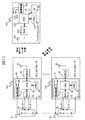
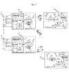
- FIG. 5 is a basic configuration diagram of a battery system according to the second embodiment of the present invention. Similar to the battery system 1 described in the first embodiment, the battery system of the present embodiment is provided in the in-vehicle system shown in FIG. The difference between this battery system and the battery system 1 described in the first embodiment is that a battery controller 201 is provided instead of the battery controller 200 of FIG. In FIG. 5, the host controller 300 is omitted.
- the battery controller 201 is further provided with an interface circuit 260 for performing wired communication with the host controller 300 in addition to the same components as the battery controller 200 of FIG.
- the battery controller 201 can be connected to the host controller 300 via a communication cable, and necessary data can be transmitted and received between the battery controller 201 and the host controller 300.
- the read / write circuit 210 may not have a low-power wireless communication function. That is, in the present embodiment, the read / write circuit 210 may have a wireless communication function using a semi-passive wireless tag in order to perform wireless communication with each cell controller 100.
- FIG. 6 is a basic configuration diagram of a battery system according to a third embodiment of the present invention. Similar to the battery system 1 described in the first embodiment, the battery system of this embodiment is provided in the in-vehicle system shown in FIG. The difference between this battery system and the battery system 1 described in the first embodiment is that a cell controller 101 is provided instead of the cell controller 100 in FIG. 2 and that the battery controller is the same as that in the second embodiment. 201.
- Each cell controller 101 is further provided with a low-power radio circuit 60 in addition to the same components as the cell controller 100 of FIG.
- the connection destination of the CPU 33 is switched to either the RFID circuit 40 or the low power radio circuit 60 under the control of the CPU 33.
- each cell controller 101 can select either the RFID circuit 40 or the low-power wireless circuit 60 and perform wireless communication using this.
- each cell controller 101 can perform semi-passive wireless communication with the battery controller 201 as described in the first embodiment.
- each cell controller 101 can perform low power wireless communication with the host controller 300.
- Which wireless communication function is used may be determined based on a predetermined setting condition or the like, or may be determined according to an instruction from the battery controller 201 or the host controller 300.
- the RFID circuit 40 or the low-power radio circuit 60 is selected according to the set value stored in a predetermined storage area in the memory 34, the above switching operation can be performed by rewriting the set value. it can.
- each cell controller 101 includes the low power radio circuit 60 for performing radio communication with the host controller 300. Since it did in this way, wireless communication can be performed between each cell controller 101 and the high-order controller 300, without going through the battery controller 201. FIG. Therefore, it is possible to reduce the processing load on the battery controller 201 and cope with the failure of the battery controller 201.
- the timing at which the measurement information is transmitted from the cell controller 100 or 101 to the battery controller 200 or 201 or the host controller 300 may be variable. For example, if the measurement information is within the normal value range, the measurement information is transmitted every second, while if the measurement information is out of the normal value range, the measurement information is sent every 0.1 second. Send. In this way, when overcharge or overdischarge occurs in each battery cell, it can be detected immediately and power consumption during normal operation can be reduced.
- the present invention may be applied to other battery systems.
- the present invention can also be applied to a battery system before being mounted on a vehicle stored in a warehouse or the like.
- the battery controller 200 and each cell controller 101 may perform wireless communication with an apparatus used for inventory management or shipping inspection, for example. If it does in this way, in the said apparatus, the state of each battery cell of the battery system made into the management object or inspection object can be easily acquired by radio
Landscapes
- Engineering & Computer Science (AREA)
- General Chemical & Material Sciences (AREA)
- Manufacturing & Machinery (AREA)
- Chemical & Material Sciences (AREA)
- Chemical Kinetics & Catalysis (AREA)
- Electrochemistry (AREA)
- Computer Networks & Wireless Communication (AREA)
- Physics & Mathematics (AREA)
- General Physics & Mathematics (AREA)
- Microelectronics & Electronic Packaging (AREA)
- Signal Processing (AREA)
- Charge And Discharge Circuits For Batteries Or The Like (AREA)
- Secondary Cells (AREA)
Abstract
各電池セルの状態を無線通信により伝送する電池システムにおいて、通信距離を拡張する。各セルコントローラ100は、対応するセルグループ10の電池セルから供給される電力を用いて、当該セルグループ10の各電池セルの状態測定結果をバッテリコントローラ200へ無線送信する。バッテリコントローラ200は、各セルコントローラ100へ無変調搬送波を連続的に送信する。一方、各セルコントローラ100は、バッテリコントローラ200から送信される無変調搬送波に対するインピーダンスを、対応するセルグループ10の各電池セルの状態測定結果に応じて所定のタイミングで変化させる。これにより、セルグループ10の各電池セルの状態測定結果をバッテリコントローラ200へ無線送信する。
Description
本発明は、電池システムに関する。
現在、地球環境問題が大きくクローズアップされる中、地球温暖化防止の為に、炭酸ガスの排出削減が求められている。たとえば、炭酸ガスの大きな排出源となっているガソリンエンジンの自動車については、ハイブリッド電気自動車や電気自動車などへの代替が始まっている。ハイブリッド電気自動車や電気自動車の動力用電源として代表的な大型二次電池は、高出力、大容量であることが必要である。そのため、これを構成する蓄電池モジュールは、一般的に、複数の電池セルを直並列接続して構成されている。
大容量の二次電池としては、リチウムイオン電池が広く知られている。リチウムイオン電池の取扱いでは、高電圧充電の防止や過放電による性能低下の防止などの措置が必要となる。そのため、ハイブリッド電気自動車や電気自動車に搭載され、各電池セルにリチウムイオン電池を用いて構成される蓄電池モジュールは、一般に、電圧、電流、温度などの電池状態を電池セルごとに監視する機能を持っている。
上記のような各電池セルの状態を監視する装置としては、たとえば下記の特許文献1に開示される状態監視装置が知られている。この状態監視装置は、各電池セルの電圧値を測定するモジュールに電磁誘導型の無線タグを設け、この無線タグを用いて各電池セルの電圧値を読み取り機へ無線信号により送信する。これにより、配線や絶縁に要するコストを削減している。
上記の状態監視装置において用いられている電磁誘導型の無線タグは、一般に通信距離が数cm~数十cm程度と短い。そのため、無線タグと読み取り機の間のレイアウトに自由度が少なく、装置の構造に制限を及ぼす可能性がある。
そこで、本発明の主な目的は、各電池セルの状態を無線通信により伝送する電池システムにおいて、通信距離を拡張することにある。
本発明による電池システムは、複数の電池セル又は1つの電池セルにより構成されるセルグループと、セルグループに対応して設けられ、セルグループの各電池セルの状態を測定するセルコントローラと、セルコントローラとの間で無線通信を行うバッテリコントローラと、を備え、セルコントローラは、セルグループの電池セルから供給される電力を用いて、セルグループの各電池セルの状態測定結果をバッテリコントローラへ無線送信する。
本発明によれば、各電池セルの状態を無線通信により伝送する電池システムにおいて、通信距離を拡張することができる。
(第1の実施形態)
図1は、本発明の一実施形態による電池システムを含む車載システムの構成を示す図である。図1に示す車載システムは、ハイブリッド電気自動車や電気自動車等の車両に搭載されるものであり、電池システム1、インバータ2、モータ3、リレーボックス4および上位コントローラ300を備える。
図1は、本発明の一実施形態による電池システムを含む車載システムの構成を示す図である。図1に示す車載システムは、ハイブリッド電気自動車や電気自動車等の車両に搭載されるものであり、電池システム1、インバータ2、モータ3、リレーボックス4および上位コントローラ300を備える。
電池システム1には、複数の電池セルによってそれぞれ構成される複数のセルグループ10が備えられており、各セルグループ10に対応して、セルコントローラ100がそれぞれ設けられている。各セルコントローラ100は、セルグループ10の各電池セルの状態(電圧、電流、温度等)を測定する。そして、セルグループ10の電池セルから供給される電力を用いて、バッテリコントローラ200との間で無線通信を行い、セルグループ10の各電池セルの状態測定結果をバッテリコントローラ200へ無線送信する。このとき行われる無線通信の詳細については、後で説明する。
バッテリコントローラ200は、各セルコントローラ100から、当該セルコントローラ100に対応するセルグループ10の各電池セルの状態測定結果を取得する。そして、取得した各電池セルの状態測定結果に基づいて、各電池セルの充電状態(SOC:State of Charge)や劣化状態(SOH:State of Health)を推定し、その推定結果を上位コントローラ300へ送信する。
上位コントローラ300は、バッテリコントローラ200から送信された各電池セルの充電状態や劣化状態の推定結果に基づいて、インバータ2やリレーボックス4を制御する。インバータ2は、リレーボックス4が導通状態のときに各セルグループ10から供給される直流電力を三相交流電力に変換してモータ3へ供給することにより、モータ3を回転駆動させて車両の駆動力を発生させる。また、車両の制動時には、モータ3により発生された三相交流回生電力を直流電力に変換して各セルグループ10へ出力することにより、各セルグループ10の電池セルを充電する。こうしたインバータ2の動作は、上位コントローラ300によって制御される。
図2は、本発明の第1の実施形態による電池システムの基本構成図である。この基本構成図では、図1に示した車載システムの各構成のうち、セルグループ10、セルコントローラ100、バッテリコントローラ200および上位コントローラ300を基本構成要素として示している。
図2において、バッテリコントローラ200は、各セルコントローラ100との間で無線通信を行う。この無線通信により、バッテリコントローラ200は、各セルコントローラ100に対して、対応するセルグループ10の各電池セルの測定情報やセルバランシング等を要求することができる。バッテリコントローラ200からの要求に応答して、各セルコントローラ100は、対応するセルグループ10の各電池セルの測定情報をバッテリコントローラ200へ送信したり、セルバランシングを実行したりする。
上位コントローラ300は、バッテリコントローラ200との間で無線通信を行う。この無線通信により、上位コントローラ300は、バッテリコントローラ200に対して、各電池セルの充電状態や劣化状態の推定を要求することができる。上位コントローラ300からの要求に応答して、バッテリコントローラ200は、各セルコントローラ100から送信されたセルグループ10の各電池セルの測定情報に基づいて各電池セルの充電状態や劣化状態を推定し、その結果を上位コントローラ300へ送信する。
なお、バッテリコントローラ200と各セルコントローラ100の間の無線通信では、比較的短い通信距離(数m程度)を有する無線方式として、いわゆるセミパッシブ方式の無線タグを用いた無線通信が利用される。一方、上位コントローラ300とバッテリコントローラ200の間の無線通信では、比較的長い通信距離(数百m程度)を有する無線方式として、いわゆる小電力無線通信が利用される。この小電力無無線通信には、たとえばIEEE802.15.4などの無線方式を使用することができる。
各セルコントローラ100は、対応するセルグループ10の各電池セルに対してそれぞれ設けられた複数のセンサ20と、処理部30と、RFID回路40と、アンテナ50とを有している。処理部30は、電源回路31と、AD変換器32と、CPU33と、メモリ34により構成される。各センサ20は、セルグループ10の各電池セルの状態を測定するためのセンサであり、電圧センサ、電流センサ、温度センサ等によって構成される。センサ20による電池セル状態の測定結果は、AD変換器32によりデジタル信号に変換され、測定情報としてCPU33へ出力される。このセンサ20およびAD変換器32により、セルグループ10の各電池セルの状態を測定する測定回路が構成される。
電源回路31は、セルグループ10の電池セルから供給される電力を受け、これに基づいて、電源電圧VccおよびVddを発生する。電源電圧Vccは、ADコンバータ32やCPU33の動作電源として用いられ、電源電圧Vddは、RFID回路40の動作電源として用いられる。なお、電源回路31は、セルグループ10を構成する各電池セルのうち、少なくともいずれか1つの電池セルから電力供給を受けることができる。
CPU33は、セルコントローラ100の動作を制御するための処理を実行する。たとえば、AD変換器32から出力された各電池セルの測定情報をメモリ34に記憶させると共に、バッテリコントローラ200からの要求に応じて、メモリ34に記憶された測定情報をバッテリコントローラ200へ無線送信するための送信処理を行う。この送信処理において、CPU33は、メモリ34から読み出した測定情報に応じてRFID回路40を制御することにより、バッテリコントローラ200から送信される無線信号に対するアンテナ50のインピーダンスを変化させる。これにより、バッテリコントローラ200からの無線信号に対する反射波として、各電池セルの状態に応じた測定情報をバッテリコントローラ200へ送信する。なお、この点については、後で詳しく説明する。また、バッテリコントローラ200からバランシング要求が送信されると、CPU33は、不図示のバランシングスイッチを制御することにより、セルグループ10の各電池セルの充電状態を均一化するためのバランシング処理を行う。これ以外にも、様々な処理をCPU33において実行することができる。
RFID回路40は、セルコントローラ100をセミパッシブ方式の無線タグとして動作させるための無線通信回路である。バッテリコントローラ200から送信されてアンテナ50により受信された無線信号は、RFID回路40により復調されてCPU33へ出力される。これにより、バッテリコントローラ200からの要求内容がCPU33により解読され、その要求内容に応じた処理がCPU33において実行される。また、RFID回路40は、電源電圧Vddを用いて、バッテリコントローラ200からの無線信号に対するアンテナ50のインピーダンスを、送信すべき測定情報に応じて、所定の通信レートに従ったタイミングで変化させる。これにより、バッテリコントローラ200から送信される無線信号の反射波として、セルグループ10の各電池セルの状態に応じた測定情報がセルコントローラ100からバッテリコントローラ200へ送信される。なお、このときのRFID回路40の動作については、後で詳細に説明する。
バッテリコントローラ200は、リードライト(R/W)回路210、CPU220、電源回路230、メモリ240およびアンテナ250を備える。電源回路230は、バッテリコントローラ200に内蔵された電池から供給される電力に基づいて、セルコントローラ100の電源回路31と同様に、電源電圧VccおよびVddを発生する。なお、バッテリコントローラ200に電池を内蔵せず、外部から供給される電力を用いてもよい。
CPU220は、リードライト回路210およびメモリ240の動作を制御する。リードライト回路210は、CPU220の制御に応じて動作し、アンテナ250を介して、セルコントローラ100や上位コントローラ300との間で無線通信を行う。このリードライト回路210は、前述のセミパッシブ方式の無線タグを用いた無線通信機能と、小電力無線通信機能との両方を有しており、通信相手に応じていずれかを選択的に使用することができる。
上位コントローラ300は、小電力無線回路310、CPU320、インタフェース回路330、電源回路340、メモリ350およびアンテナ360を備える。電源回路340は、バッテリコントローラ200の電源回路230と同様に、上位コントローラ300に内蔵された電池から供給される電力に基づいて、電源電圧VccおよびVddを発生する。なお、上位コントローラ300に電池を内蔵せず、外部から供給される電力を用いてもよい。
CPU320は、小電力無線回路310、インタフェース回路330およびメモリ350の動作を制御する。小電力無線回路310は、CPU320の制御に応じて動作し、アンテナ360を介して、バッテリコントローラ200との間で小電力無線方式による無線通信を行う。インタフェース回路330は、上位コントローラ300と外部装置(たとえば、図1のインバータ2)との間で行われるデータ通信のインタフェース処理を行う。
次に、セルコントローラ100とバッテリコントローラ200の間で行われる無線通信について説明する。図3は、バッテリコントローラ200からセルコントローラ100への無線送信方法の説明図である。
バッテリコントローラ200からセルコントローラ100への無線送信を行う際、バッテリコントローラ200は、図3に示すように、リードライト回路210からアンテナ250を介して、搬送波周波数の振幅を送信データに応じて変化させたASK変調波をセルコントローラ100へ送信する。このASK変調波は、セルコントローラ100においてアンテナ50により受信され、RFID回路40内の復調器41により復調される。復調器41は、受信したASK変調波を復調することでクロックとデータを再生し、受信データとしてCPU33へ出力する。受信データは、CPU33によりメモリ34に記憶され、必要に応じて読み出される。
なお、図3ではASK変調波を用いた例を説明したが、他の変調方式を用いてもよい。たとえば、搬送波周波数の位相を送信データに応じて変化させたPSK変調波を用いたり、これらを組み合わせた変調方式を用いたりすることができる。
図4は、セルコントローラ100からバッテリコントローラ200への無線送信方法の説明図である。
セルコントローラ100からバッテリコントローラ200への無線通信を行う際、バッテリコントローラ200は、図4に示すように、リードライト回路210からアンテナ250を介して、無変調の搬送波を連続的に送信する。一方、セルコントローラ100は、RFID回路40内の変調器42において、所定の通信レートに従って、アンテナ50のインピーダンスを送信データに応じて変化させる。たとえば、変調器42内にインピーダンス整合回路とスイッチを設け、このスイッチを送信データのビットが「1」である場合と「0」である場合とで切り替えることにより、インピーダンス整合回路とアンテナ50の間の接続状態を制御して、インピーダンスを変化させる。なお、このときのスイッチの動作電源には、対応するセルグループ10の電池セルから供給される電力に基づいて電源回路31により生成された前述の電源電圧Vddが用いられる。
上記のようにしてアンテナ50のインピーダンスを変化させながら、バッテリコントローラ200から送信される無変調搬送波をセルコントローラ100が受信すると、そのときのインピーダンスの状態に応じた反射波がアンテナ50から送信される。すなわち、インピーダンス整合が取れた状態でバッテリコントローラ200からの無変調搬送波を受信した場合は、アンテナ50において無変調搬送波が全て吸収されるため、反射波は送信されない。一方、インピーダンス整合が取れていない状態でバッテリコントローラ200からの無変調搬送波を受信した場合は、無変調搬送波の一部がアンテナ50から反射波として送信される。このようにして、バッテリコントローラ200からの無変調搬送波に対する反射波を送信データに応じて変化させることで、セルコントローラ100からバッテリコントローラ200への無線通信を行うことができる。
ここで、本発明の無線通信方式による通信距離について説明する。従来のパッシブ方式による電磁誘導型の無線タグでは、読み取り機から送信された無線信号の受信電力を利用して、無線タグから読み取り機への無線通信を行う必要がある。この場合の通信距離は、一般的に数cm程度である。
一方、本発明の無線通信方式では、前述のように、各セルコントローラ100において、対応するセルグループ10の電池セルから供給される電力を用いて、アンテナ50のインピーダンスを変化させる。これにより、無変調搬送波に対する反射波を利用したセミパッシブ方式の無線通信が行われる。
一般に、自由空間における無線信号の伝播ロスL(dB)は、以下の式(1)により表すことができる。式(1)において、d(m)はアンテナ間の距離を表し、λ(m)は無線信号の波長を表している。
L=20log(4πd/λ) ・・・(1)
L=20log(4πd/λ) ・・・(1)
ここで、読み取り機であるバッテリコントローラ200のリードライト回路210における送信電力を1W(30dBm)とし、最小受信感度を-80dBmとする。この場合、往復の伝播ロスが110dB以下の範囲内で、セルコントローラ100からバッテリコントローラ200への無線通信が可能である。すなわち、伝播ロスL=55dBに相当する距離が通信距離となる。
たとえば、無線信号の周波数を900MHz(λ=0.33m)とした場合、上記の式(1)においてL=55dBとすると、通信距離はd=14.9mと求められる。したがって、本発明によるセミパッシブ方式の無線通信では、前述のような従来のパッシブ方式の無線通信の場合と比べて、通信距離を拡張できることが分かる。
以上説明した本発明の第1の実施形態によれば、以下の作用効果を奏する。
(1)電池システム1において、各セルコントローラ100は、対応するセルグループ10の電池セルから供給される電力を用いて、当該セルグループ10の各電池セルの状態測定結果をバッテリコントローラ200へ無線送信する。このようにしたので、各電池セルの状態を無線通信により伝送する電池システム1において、通信距離を拡張することができる。
(2)バッテリコントローラ200は、各セルコントローラ100へ無変調搬送波を連続的に送信する。一方、各セルコントローラ100は、バッテリコントローラ200から送信される無変調搬送波に対するインピーダンスを、対応するセルグループ10の各電池セルの状態測定結果に応じて所定のタイミングで変化させる。これにより、セルグループ10の各電池セルの状態測定結果をバッテリコントローラ200へ無線送信する。このようにしたので、各セルコントローラ100での消費電力を抑えつつ、通信距離を拡張することができる。
(3)各セルコントローラ100は、対応するセルグループ10の各電池セルの状態を測定するための測定回路を構成するセンサ20およびAD変換器32と、電源回路31と、アンテナ50と、RFID回路40とを備える。RFID回路40は、電源回路31により発生された電源電圧Vddを用いて、センサ20およびAD変換器32により測定されたセルグループ10の各電池セルの状態に応じて、アンテナ50のインピーダンスを変化させる。このようにしたので、各セルコントローラ100において、対応するセルグループ10の各電池セルの状態を確実に測定し、その測定結果をバッテリコントローラ200へ送信することができる。
(4)バッテリコントローラ200は、各セルコントローラ100との間で行われる無線通信とは異なる無線方式を用いて、上位コントローラ300との間で無線通信を行う。このようにしたので、バッテリコントローラ200と上位コントローラ300の間の配線を省略し、さらなる低コスト化を図ることができる。
(第2の実施形態)
図5は、本発明の第2の実施形態による電池システムの基本構成図である。本実施形態の電池システムは、第1の実施形態で説明した電池システム1と同様に、図1に示した車載システムにおいて備えられるものである。この電池システムと、第1の実施形態で説明した電池システム1との違いは、図2のバッテリコントローラ200に替えて、バッテリコントローラ201を有する点である。なお、図5では、上位コントローラ300を省略している。
バッテリコントローラ201には、図2のバッテリコントローラ200と同様の各構成要素に加えて、上位コントローラ300との間で有線通信を行なうためのインタフェース回路260がさらに設けられている。このインタフェース回路260により、通信用ケーブルを介してバッテリコントローラ201を上位コントローラ300に接続して、バッテリコントローラ201と上位コントローラ300の間で必要なデータの送受信を行うことができる。
なお、本実施形態のバッテリコントローラ201では、前述の第1の実施形態とは異なり、リードライト回路210が小電力無線通信機能を有していなくてもよい。すなわち、本実施形態において、リードライト回路210は、各セルコントローラ100との間で無線通信を行うために、セミパッシブ方式の無線タグを用いた無線通信機能を有していればよい。
以上説明した本発明の第2の実施形態によれば、バッテリコントローラ201は、上位コントローラ300との間で有線通信を行うためのインタフェース回路260を備える。このようにしたので、バッテリコントローラ201において、リードライト回路210の小電力無線通信機能を省略できるため、低コスト化を図ることができる。
(第3の実施形態)
図6は、本発明の第3の実施形態による電池システムの基本構成図である。本実施形態の電池システムは、第1の実施形態で説明した電池システム1と同様に、図1に示した車載システムにおいて備えられるものである。この電池システムと、第1の実施形態で説明した電池システム1との違いは、図2のセルコントローラ100に替えてセルコントローラ101を有する点と、前述の第2の実施形態と同様のバッテリコントローラ201を有する点である。
(第3の実施形態)
図6は、本発明の第3の実施形態による電池システムの基本構成図である。本実施形態の電池システムは、第1の実施形態で説明した電池システム1と同様に、図1に示した車載システムにおいて備えられるものである。この電池システムと、第1の実施形態で説明した電池システム1との違いは、図2のセルコントローラ100に替えてセルコントローラ101を有する点と、前述の第2の実施形態と同様のバッテリコントローラ201を有する点である。
各セルコントローラ101には、図2のセルコントローラ100と同様の各構成要素に加えて、小電力無線回路60がさらに設けられている。各セルコントローラ101では、CPU33の制御により、CPU33の接続先をRFID回路40または小電力無線回路60のどちらかに切り替える。この切り替え動作により、各セルコントローラ101は、RFID回路40または小電力無線回路60のいずれか一方を選択し、これを用いて無線通信を行うことができる。
RFID回路40を選択した場合、各セルコントローラ101は、第1の実施形態で説明したように、バッテリコントローラ201との間でセミパッシブ方式の無線通信を行うことができる。一方、小電力無線回路60を選択した場合、各セルコントローラ101は、上位コントローラ300との間で小電力無線方式の無線通信を行うことができる。なお、どちらの無線通信機能を用いるかは、予め定められた設定条件等に基づいて決定してもよいし、バッテリコントローラ201または上位コントローラ300からの指示に応じて決定してもよい。たとえば、メモリ34内の所定の記憶領域に記憶されている設定値に従ってRFID回路40または小電力無線回路60を選択する場合、この設定値を書き換えることで、上記のような切り替え動作を行うことができる。あるいは、各セルコントローラ101において受信した無線信号の周波数や電界強度に基づいて、バッテリコントローラ201と上位コントローラ300のどちらから無線信号が送信されているかを判断し、その判断結果に応じて切り替え動作を行ってもよい。
以上説明した本発明の第3の実施形態によれば、各セルコントローラ101は、上位コントローラ300との間で無線通信を行うための小電力無線回路60を備える。このようにしたので、バッテリコントローラ201を介さずに、各セルコントローラ101と上位コントローラ300の間で無線通信を行うことができる。そのため、バッテリコントローラ201の処理負荷を軽減すると共に、バッテリコントローラ201の故障時にも対処可能である。
なお、以上説明した各実施の形態において、セルコントローラ100または101からバッテリコントローラ200または201、あるいは上位コントローラ300へ測定情報を送信するタイミングを可変としてもよい。たとえば、測定情報が正常値の範囲内である場合は、測定情報を1秒ごとに送信する一方で、測定情報が正常値の範囲を外れている場合は、測定情報を0.1秒ごとに送信する。このようにすれば、各電池セルにおいて過充電や過放電が生じたときには即時に検知できると共に、正常時の消費電力を低減することができる。
また、以上説明した各実施の形態では、図1の車載システムに含まれる電池システムにおける適用例を説明したが、本発明を他の電池システムに適用してもよい。たとえば、倉庫等に保管されている車載前の電池システムにおいても、本発明を適用可能である。その場合、上位コントローラ300に替えて、たとえば在庫管理や出荷検査に用いられる装置との間でバッテリコントローラ200や各セルコントローラ101が無線通信を行うようにしてもよい。このようにすれば、当該装置において、管理対象や検査対象とする電池システムの各電池セルの状態を無線通信により容易に取得することができる。そのため、管理工数や検査工数を低減すると共に、いずれかの電池セルにおいて異常が生じた場合は、その電池セルを容易に特定することができる。
以上説明した各実施の形態は、単独で適用することも可能であるし、いずれか任意のものを組み合わせて適用することも可能である。また、上記各実施の形態や各種の変形例はあくまで一例であり、発明の特徴が損なわれない限り、本発明はこれらの内容に限定されるものではない。
10・・・・セルグループ
20・・・・センサ
30・・・・処理部
31・・・・電源回路
32・・・・AD変換器
33・・・・CPU
34・・・・メモリ
40・・・・RFID回路
41・・・・復調器
42・・・・変調器
50・・・・アンテナ
60・・・・小電力無線回路
100、101・・・セルコントローラ
200、201・・・バッテリコントローラ
210・・・リードライト回路
220・・・CPU
230・・・電源回路
240・・・メモリ
250・・・アンテナ
260・・・インタフェース回路
300・・・上位コントローラ
310・・・小電力無線回路
320・・・CPU
330・・・インタフェース回路
340・・・電源回路
350・・・メモリ
360・・・アンテナ
Claims (6)
- 複数の電池セル又は1つの電池セルにより構成されるセルグループと、
前記セルグループに対応して設けられ、前記セルグループの各電池セルの状態を測定するセルコントローラと、
前記セルコントローラとの間で無線通信を行うバッテリコントローラと、を備え、
前記セルコントローラは、前記セルグループの電池セルから供給される電力を用いて、前記セルグループの各電池セルの状態測定結果を前記バッテリコントローラへ無線送信する、電池システム。 - 請求項1に記載の電池システムにおいて、
前記バッテリコントローラは、前記セルコントローラへ無変調搬送波を連続的に送信し、
前記セルコントローラは、前記バッテリコントローラから送信される無変調搬送波に対するインピーダンスを、前記セルグループの各電池セルの状態測定結果に応じて所定のタイミングで変化させることにより、前記セルグループの各電池セルの状態測定結果を前記バッテリコントローラへ無線送信する、電池システム。 - 請求項2に記載の電池システムにおいて、
前記セルコントローラは、
前記セルグループの各電池セルの状態を測定するための測定回路と、
前記セルグループの電池セルから供給される電力に基づいて電源電圧を発生する電源回路と、
前記バッテリコントローラから送信される無変調搬送波を受信するためのアンテナと、
前記電源回路により発生された電源電圧を用いて、前記測定回路により測定された前記セルグループの各電池セルの状態に応じて、前記アンテナのインピーダンスを変化させる無線通信回路と、を備える、電池システム。 - 請求項1乃至3のいずれか一項に記載の電池システムにおいて、
前記バッテリコントローラは、前記セルコントローラとの間で行われる無線通信とは異なる無線方式を用いて、上位コントローラとの間で無線通信を行う、電池システム。 - 請求項1乃至3のいずれか一項に記載の電池システムにおいて、
前記バッテリコントローラは、上位コントローラとの間で有線通信を行うためのインタフェース回路を備える、電池システム。 - 請求項1乃至3のいずれか一項に記載の電池システムにおいて、
前記セルコントローラは、上位コントローラとの間で無線通信を行うための無線回路を備える、電池システム。
Priority Applications (3)
| Application Number | Priority Date | Filing Date | Title |
|---|---|---|---|
| EP14775401.4A EP2980912B1 (en) | 2013-03-29 | 2014-01-27 | Battery system |
| CN201480003801.1A CN105122538B (zh) | 2013-03-29 | 2014-01-27 | 电池系统 |
| US14/758,016 US20160301112A1 (en) | 2013-03-29 | 2014-01-27 | Battery system |
Applications Claiming Priority (2)
| Application Number | Priority Date | Filing Date | Title |
|---|---|---|---|
| JP2013-073181 | 2013-03-29 | ||
| JP2013073181A JP5879294B2 (ja) | 2013-03-29 | 2013-03-29 | 電池システム |
Publications (1)
| Publication Number | Publication Date |
|---|---|
| WO2014156264A1 true WO2014156264A1 (ja) | 2014-10-02 |
Family
ID=51623266
Family Applications (1)
| Application Number | Title | Priority Date | Filing Date |
|---|---|---|---|
| PCT/JP2014/051613 WO2014156264A1 (ja) | 2013-03-29 | 2014-01-27 | 電池システム |
Country Status (5)
| Country | Link |
|---|---|
| US (1) | US20160301112A1 (ja) |
| EP (1) | EP2980912B1 (ja) |
| JP (1) | JP5879294B2 (ja) |
| CN (1) | CN105122538B (ja) |
| WO (1) | WO2014156264A1 (ja) |
Cited By (5)
| Publication number | Priority date | Publication date | Assignee | Title |
|---|---|---|---|---|
| WO2018037776A1 (ja) * | 2016-08-24 | 2018-03-01 | 株式会社日立製作所 | 電池制御システム |
| WO2018131338A1 (ja) * | 2017-01-12 | 2018-07-19 | 株式会社日立製作所 | 無線電池システム |
| CN109416389A (zh) * | 2016-06-28 | 2019-03-01 | 凌力尔特科技有限责任公司 | 用于电池系统的无线传感器 |
| US20220029204A1 (en) * | 2019-02-01 | 2022-01-27 | Lg Energy Solution, Ltd. | Battery system and slave battery management system |
| WO2024009616A1 (ja) * | 2022-07-06 | 2024-01-11 | 日立Astemo株式会社 | 無線通信システム |
Families Citing this family (15)
| Publication number | Priority date | Publication date | Assignee | Title |
|---|---|---|---|---|
| WO2016072002A1 (ja) * | 2014-11-07 | 2016-05-12 | 株式会社日立製作所 | 蓄電管理システム |
| JP6421625B2 (ja) * | 2015-01-30 | 2018-11-14 | 日立化成株式会社 | 無線電池システムおよび無線システム |
| KR102132315B1 (ko) * | 2016-06-08 | 2020-07-09 | 히타치가세이가부시끼가이샤 | 무선 통신 시스템 |
| US10787193B2 (en) * | 2016-07-01 | 2020-09-29 | Hitachi Automotive Systems, Ltd. | Drive control device and control method for electric motor |
| US11267342B2 (en) | 2017-02-24 | 2022-03-08 | Vehicle Energy Japan Inc. | Battery control system |
| KR102173777B1 (ko) * | 2017-07-25 | 2020-11-03 | 주식회사 엘지화학 | 마스터 배터리 관리 유닛 및 이를 포함하는 배터리팩 |
| KR102173778B1 (ko) * | 2017-07-25 | 2020-11-03 | 주식회사 엘지화학 | 배터리 관리 유닛 및 이를 포함하는 배터리팩 |
| KR102203247B1 (ko) * | 2017-10-10 | 2021-01-13 | 주식회사 엘지화학 | 무선 배터리 관리 장치 및 이를 포함하는 배터리팩 |
| JP2019082399A (ja) * | 2017-10-30 | 2019-05-30 | ラピスセミコンダクタ株式会社 | 電池測定装置、及び電池監視システム |
| DE102018200579A1 (de) * | 2018-01-15 | 2019-07-18 | Audi Ag | Verfahren zum Betreiben einer Energiespeichereinrichtung für ein Kraftfahrzeug sowie entsprechende Energiespeichereinrichtung |
| US10974616B2 (en) * | 2018-06-22 | 2021-04-13 | GM Global Technology Operations LLC | High-voltage system with low-voltage control architecture and method |
| EP3675311A1 (en) | 2018-12-28 | 2020-07-01 | Vito NV | Energy storage string with energy management device |
| JP7156212B2 (ja) * | 2019-08-22 | 2022-10-19 | 株式会社デンソー | 電池監視装置 |
| WO2021053723A1 (ja) * | 2019-09-17 | 2021-03-25 | 株式会社 東芝 | 蓄電池装置 |
| JP6988929B2 (ja) * | 2020-01-15 | 2022-01-05 | 株式会社デンソー | 電池パック |
Citations (5)
| Publication number | Priority date | Publication date | Assignee | Title |
|---|---|---|---|---|
| JP2005135762A (ja) | 2003-10-30 | 2005-05-26 | Denso Corp | 燃料電池の状態監視装置 |
| JP2007504537A (ja) * | 2003-08-29 | 2007-03-01 | シンボル テクノロジーズ インコーポレイテッド | 選択可能なバックスキャッタパラメータを持つrfidシステム |
| JP2007141464A (ja) * | 2005-11-14 | 2007-06-07 | Hitachi Vehicle Energy Ltd | 二次電池モジュール、電池情報管理装置、電池情報管理システム、二次電池リユースシステム、二次電池回収・販売システム、二次電池リユース方法および二次電池回収・販売方法 |
| JP2007225614A (ja) * | 2006-02-23 | 2007-09-06 | National Semiconductor Corp | 線形性補正を具備した周波数比デジタル化温度センサー |
| JP2008220074A (ja) * | 2007-03-06 | 2008-09-18 | Hitachi Vehicle Energy Ltd | 蓄電装置,蓄電池管理制御装置及びモータ駆動装置 |
Family Cites Families (15)
| Publication number | Priority date | Publication date | Assignee | Title |
|---|---|---|---|---|
| DE69940909D1 (de) * | 1998-07-21 | 2009-07-02 | Metrixx Ltd | Signalisierungssystem |
| US7606537B2 (en) | 2004-02-10 | 2009-10-20 | Colin Dugald Brodhead | System and method for transmitting data via wave reflection |
| US20060012464A1 (en) * | 2004-07-01 | 2006-01-19 | Zvi Nitzan | Battery-assisted backscatter RFID transponder |
| US20070182576A1 (en) * | 2006-02-09 | 2007-08-09 | 1673892 Ontario, Inc. | Remote battery monitoring |
| US9769547B2 (en) * | 2008-08-12 | 2017-09-19 | Collision Communications, Inc. | Method for simultaneous detection of a plurality of RFID tags using multiuser detection |
| US8773243B1 (en) * | 2008-09-05 | 2014-07-08 | Intelleflex Corporation | Battery assisted RFID tag receiver training and synchronization methods |
| JP2010081716A (ja) | 2008-09-25 | 2010-04-08 | Toshiba Corp | 電池情報取得装置 |
| US8723525B2 (en) | 2009-07-06 | 2014-05-13 | Qualcomm Incorporated | Sensor in battery |
| US8390249B2 (en) * | 2009-11-30 | 2013-03-05 | Broadcom Corporation | Battery with integrated wireless power receiver and/or RFID |
| KR101702861B1 (ko) | 2009-12-24 | 2017-02-23 | 삼성전자주식회사 | 무선 전력 전송 장치 및 방법 |
| US8587318B2 (en) * | 2010-07-27 | 2013-11-19 | GM Global Technology Operations LLC | Sensor arrangement for an energy storage device and a method of using the same |
| JP6147668B2 (ja) * | 2010-11-02 | 2017-06-14 | ナビタス ソリューションズ,インコーポレイテッド | スマート電池管理システムのための無線電池エリアネットワーク |
| EP2673889B1 (en) * | 2011-02-07 | 2020-04-15 | Philips IP Ventures B.V. | Method and device of providing communications in a wireless power transfer system |
| FR2976738B1 (fr) * | 2011-06-14 | 2013-07-19 | Commissariat Energie Atomique | Systeme de batteries d'accumulateurs a supervision simplifiee |
| EP2778699A4 (en) * | 2011-11-08 | 2015-07-29 | Shin Kobe Electric Machinery | BATTERY CONDITION MONITORING SYSTEM |
-
2013
- 2013-03-29 JP JP2013073181A patent/JP5879294B2/ja active Active
-
2014
- 2014-01-27 EP EP14775401.4A patent/EP2980912B1/en active Active
- 2014-01-27 CN CN201480003801.1A patent/CN105122538B/zh active Active
- 2014-01-27 WO PCT/JP2014/051613 patent/WO2014156264A1/ja active Application Filing
- 2014-01-27 US US14/758,016 patent/US20160301112A1/en not_active Abandoned
Patent Citations (5)
| Publication number | Priority date | Publication date | Assignee | Title |
|---|---|---|---|---|
| JP2007504537A (ja) * | 2003-08-29 | 2007-03-01 | シンボル テクノロジーズ インコーポレイテッド | 選択可能なバックスキャッタパラメータを持つrfidシステム |
| JP2005135762A (ja) | 2003-10-30 | 2005-05-26 | Denso Corp | 燃料電池の状態監視装置 |
| JP2007141464A (ja) * | 2005-11-14 | 2007-06-07 | Hitachi Vehicle Energy Ltd | 二次電池モジュール、電池情報管理装置、電池情報管理システム、二次電池リユースシステム、二次電池回収・販売システム、二次電池リユース方法および二次電池回収・販売方法 |
| JP2007225614A (ja) * | 2006-02-23 | 2007-09-06 | National Semiconductor Corp | 線形性補正を具備した周波数比デジタル化温度センサー |
| JP2008220074A (ja) * | 2007-03-06 | 2008-09-18 | Hitachi Vehicle Energy Ltd | 蓄電装置,蓄電池管理制御装置及びモータ駆動装置 |
Non-Patent Citations (1)
| Title |
|---|
| See also references of EP2980912A1 |
Cited By (12)
| Publication number | Priority date | Publication date | Assignee | Title |
|---|---|---|---|---|
| CN109416389A (zh) * | 2016-06-28 | 2019-03-01 | 凌力尔特科技有限责任公司 | 用于电池系统的无线传感器 |
| US10914789B2 (en) | 2016-06-28 | 2021-02-09 | Analog Devices International Unlimited Company | Wireless sensing for battery systems |
| CN109416389B (zh) * | 2016-06-28 | 2021-06-29 | 亚德诺半导体国际无限责任公司 | 用于电池系统的无线传感器 |
| WO2018037776A1 (ja) * | 2016-08-24 | 2018-03-01 | 株式会社日立製作所 | 電池制御システム |
| JPWO2018037776A1 (ja) * | 2016-08-24 | 2019-02-14 | 株式会社日立製作所 | 電池制御システム |
| JP2021114901A (ja) * | 2016-08-24 | 2021-08-05 | 株式会社日立製作所 | 電池制御システム |
| US11437840B2 (en) | 2016-08-24 | 2022-09-06 | Hitachi, Ltd. | Battery control system |
| JP7307115B2 (ja) | 2016-08-24 | 2023-07-11 | ビークルエナジージャパン株式会社 | 電池制御システム |
| WO2018131338A1 (ja) * | 2017-01-12 | 2018-07-19 | 株式会社日立製作所 | 無線電池システム |
| JPWO2018131338A1 (ja) * | 2017-01-12 | 2019-11-07 | ビークルエナジージャパン株式会社 | 無線電池システム |
| US20220029204A1 (en) * | 2019-02-01 | 2022-01-27 | Lg Energy Solution, Ltd. | Battery system and slave battery management system |
| WO2024009616A1 (ja) * | 2022-07-06 | 2024-01-11 | 日立Astemo株式会社 | 無線通信システム |
Also Published As
| Publication number | Publication date |
|---|---|
| EP2980912A4 (en) | 2017-01-18 |
| EP2980912B1 (en) | 2018-03-14 |
| JP2014197345A (ja) | 2014-10-16 |
| JP5879294B2 (ja) | 2016-03-08 |
| US20160301112A1 (en) | 2016-10-13 |
| CN105122538B (zh) | 2018-03-13 |
| EP2980912A1 (en) | 2016-02-03 |
| CN105122538A (zh) | 2015-12-02 |
Similar Documents
| Publication | Publication Date | Title |
|---|---|---|
| JP5879294B2 (ja) | 電池システム | |
| US10193190B2 (en) | Battery control system | |
| JP6171027B2 (ja) | 電池システム | |
| US11038216B2 (en) | Wireless battery management system and battery pack including same | |
| US11070067B2 (en) | Battery management unit and battery pack including same | |
| US9987945B2 (en) | Radio battery system, and cell controller and battery controller that have radio battery system | |
| JP6630156B2 (ja) | バッテリ監視装置 | |
| US10243415B1 (en) | Mobile power transmitter | |
| JP6847981B2 (ja) | 無線電池システム | |
| CN203434641U (zh) | 一种电动汽车的无线充电通信系统 | |
| CN104052088A (zh) | 用于电动汽车的无线充电系统 | |
| Sanborn et al. | Standards and methods of power control for variable power bidirectional wireless power transfer | |
| KR102296151B1 (ko) | 무선 네트워크 환경에서 파워 비콘을 이용한 에너지 하비스팅 방법 및 시스템 | |
| JP7307115B2 (ja) | 電池制御システム | |
| CN108629956A (zh) | 监视系统和监视方法 | |
| JP6896838B2 (ja) | 電池制御システム | |
| CN113428038B (zh) | 充电方法、装置、电子设备和计算机可读介质 |
Legal Events
| Date | Code | Title | Description |
|---|---|---|---|
| 121 | Ep: the epo has been informed by wipo that ep was designated in this application |
Ref document number: 14775401 Country of ref document: EP Kind code of ref document: A1 |
|
| DPE1 | Request for preliminary examination filed after expiration of 19th month from priority date (pct application filed from 20040101) | ||
| WWE | Wipo information: entry into national phase |
Ref document number: 14758016 Country of ref document: US |
|
| WWE | Wipo information: entry into national phase |
Ref document number: 2014775401 Country of ref document: EP |
|
| NENP | Non-entry into the national phase |
Ref country code: DE |